EP2990883A1 - Ensemble balancier-spiral d'horlogerie - Google Patents
Ensemble balancier-spiral d'horlogerie Download PDFInfo
- Publication number
- EP2990883A1 EP2990883A1 EP14182777.4A EP14182777A EP2990883A1 EP 2990883 A1 EP2990883 A1 EP 2990883A1 EP 14182777 A EP14182777 A EP 14182777A EP 2990883 A1 EP2990883 A1 EP 2990883A1
- Authority
- EP
- European Patent Office
- Prior art keywords
- balance
- arm
- feeder
- front face
- rod
- Prior art date
- Legal status (The legal status is an assumption and is not a legal conclusion. Google has not performed a legal analysis and makes no representation as to the accuracy of the status listed.)
- Withdrawn
Links
- 230000000284 resting effect Effects 0.000 claims description 5
- BASFCYQUMIYNBI-UHFFFAOYSA-N platinum Chemical compound [Pt] BASFCYQUMIYNBI-UHFFFAOYSA-N 0.000 description 2
- 230000002349 favourable effect Effects 0.000 description 1
- 239000007769 metal material Substances 0.000 description 1
- 238000000034 method Methods 0.000 description 1
- 238000012986 modification Methods 0.000 description 1
- 230000004048 modification Effects 0.000 description 1
- 229910052697 platinum Inorganic materials 0.000 description 1
- 230000000717 retained effect Effects 0.000 description 1
Images
Classifications
-
- G—PHYSICS
- G04—HOROLOGY
- G04B—MECHANICALLY-DRIVEN CLOCKS OR WATCHES; MECHANICAL PARTS OF CLOCKS OR WATCHES IN GENERAL; TIME PIECES USING THE POSITION OF THE SUN, MOON OR STARS
- G04B18/00—Mechanisms for setting frequency
-
- G—PHYSICS
- G04—HOROLOGY
- G04B—MECHANICALLY-DRIVEN CLOCKS OR WATCHES; MECHANICAL PARTS OF CLOCKS OR WATCHES IN GENERAL; TIME PIECES USING THE POSITION OF THE SUN, MOON OR STARS
- G04B18/00—Mechanisms for setting frequency
- G04B18/006—Mechanisms for setting frequency by adjusting the devices fixed on the balance
-
- G—PHYSICS
- G04—HOROLOGY
- G04B—MECHANICALLY-DRIVEN CLOCKS OR WATCHES; MECHANICAL PARTS OF CLOCKS OR WATCHES IN GENERAL; TIME PIECES USING THE POSITION OF THE SUN, MOON OR STARS
- G04B18/00—Mechanisms for setting frequency
- G04B18/04—Adjusting the beat of the pendulum, balance, or the like, e.g. putting into beat
- G04B18/06—Adjusting the beat of the pendulum, balance, or the like, e.g. putting into beat by setting the collet or the stud of a hairspring
Definitions
- the invention relates to a sprung-balance assembly whose balance has means for adjusting the inertia.
- the invention also relates to a watch movement comprising such a system and a timepiece equipped with such a movement.
- the invention particularly aims to overcome the various disadvantages of these known techniques.
- an object of the invention is to provide a pendulum for obtaining a compact watch movement.
- Another object of the invention is to provide a balance spring system allowing easy access to the flyweights for adjusting the inertia after the casing.
- the invention also aims, at least in a particular embodiment, to provide a balance spring system that is simple to implement and inexpensive.
- a balance-balance system comprising at least one balance oscillating about a pivot axis via a control shaft.
- balance wheel mounted between a plate and a bridge (9) and aligned on said pivot axis, and at least one spiral of which an inner turn is fixed to said balance shaft or to a ferrule mounted integral with said balance shaft and an outer turn of which is fixed to a pin integral with the bridge carrying said shaft, said balance having a balance hub, a serge, at least one arm connecting said hub to said serge, a front face having a recess and a rear face, said at least one arm comprising a housing for receiving and maintaining a feeder, and said hairspring being mounted facing the front face of the balance.
- said flyweight is mounted on the side of the rear face of the balance, on said at least one arm of said balance, and in that the distance between the bottom of the core of the front face of the balance and the balance is within a predetermined range of 0.05mm to 1.50mm
- the invention also relates to a watch movement comprising a balance-balance oscillator system according to the invention.
- the invention also relates to a timepiece comprising a watch movement according to the invention.
- the object of the present invention by its different functional and structural aspects described above, makes it possible to obtain a clockwork movement comprising a balance-spring system whose access to the means for adjusting the inertia is particularly easy. .
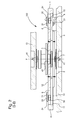
- the invention thus relates to a sprung balance-balance system, intended to be incorporated in an oscillating mechanism within a watch movement, and comprising at least one rocker 1 oscillating about a pivot axis P via a balance shaft 40 aligned on the axis P and at least one hairspring 2.
- the rocker shaft 40 is mounted between a plate 13 and a bridge 9, the rocker shaft 40 having at each of its ends a tapered pivot 41 to allow the rocker shaft 40 to pivot about the axis pivoting P by limiting the friction.
- An inner turn (not visible in the figures) of the hairspring 2 is fixed to the balance shaft 40 or to a shell 7 which can be integral with the hairspring 2 mounted integral with the balance shaft 40 and an outer turn 21 of the hairspring 2 is fixed to a stud 8 secured to a bridge 9.
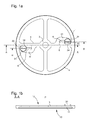
- the balance 1 comprises a hub 3 carrying the balance shaft 40, a serge 4, at least one arm 5 connecting the hub 3 to the serge 4, a front face 10 having a core 11 and a flat rear face 12 which can also be embedded.
- the arm 5 comprises a housing 6 for receiving and holding at least one feeder 30, and the hairspring 2 is mounted opposite the front face 10 of the rocker 1 receiving the casing 11.
- the rocker 1 comprises rigid parts constituted by the hub 3, the serge 4, and the arm 5 connecting the serge 4 to the hub 2.
- the housing 6 is delimited, on the one hand by a rigid portion of the balance 1, and on the other hand a portion 61 elastically deformable.
- the arm 5 comprises a housing 6 for receiving and pinching in the position of a rod 32 of a flyweight 30.
- This weight 30 comprises a head 31 having handling means such as a control profile 33 arranged to cooperate with a tool, such as a screwdriver.
- a tool such as a screwdriver.
- the rod 32 of the weight 30 extends the head 31, which is of greater diameter than that of the rod 32.
- the diameter of the rod 32 of the weight 30 is chosen greater than the width of the housing 6 so that the rod 32 is retained by the portion 61 elastically deformable, the portion 61 exerting a restoring force.
- the length of the rod 32 does not exceed the thickness of the arm 5, so that the rod 32 is not protruding and thus optimize the arrangement of parts within the movement to gain compactness.
- This simple configuration of a feeder 30 consisting solely of the head 31 and the rod 32 is favorable for mounting the feeder on the balance 1 from the bottom of the latter.
- the weight 30, once pinched in the housing 6, is angularly adjustable by means of a tool without being disturbed by the spiral 2 or by the limited space available.
- the weight 30 comprises an unbalance made by means of a flat portion 34 made on the head 31, as visible on the figure 1 a, to allow the inertia adjustment of the balance 1.
- the weight 30 is mounted on the side of the rear face 12 of the balance 1, the head 31 resting against the rear face 12 of the balance 1 under the arm 5, the distance between the bottom of the face of the yoke before 10 of the balance 1 and the balance spring 2 is in a range V predetermined between 0.05mm and 1.50mm. More preferably, the predetermined interval V is between 0.10mm and 0.70mm. Such an arrangement provides a compact arrangement and thus reduce the size of the watch movement.
- the rod 32 is flush with the bottom of the core 11 of the front face 10 of the rocker 1 so that the core 11 does not have a projecting element, the stud 8 can then be arranged at most near the serge 4, the piton 8 can even be closer to the bottom of the hole 11.
- the arm 5, the serge 4 and the hub 3 form a single piece element, the rocker 1 can be made of a metal material.
- the invention also relates to a watch movement and a timepiece equipped with a balance spring system according to the invention.
Landscapes
- Physics & Mathematics (AREA)
- General Physics & Mathematics (AREA)
- Springs (AREA)
- Gears, Cams (AREA)
- Electromechanical Clocks (AREA)
Priority Applications (8)
| Application Number | Priority Date | Filing Date | Title |
|---|---|---|---|
| EP14182777.4A EP2990883A1 (fr) | 2014-08-29 | 2014-08-29 | Ensemble balancier-spiral d'horlogerie |
| JP2017510864A JP6293973B2 (ja) | 2014-08-29 | 2015-08-19 | 計時器のバランス車ばねアセンブリー |
| US15/505,270 US10061269B2 (en) | 2014-08-29 | 2015-08-19 | Balance wheel-spring assembly of timepiece |
| RU2017110089A RU2688418C2 (ru) | 2014-08-29 | 2015-08-19 | Узел баланса с пружиной для часов |
| PCT/EP2015/069085 WO2016030257A1 (fr) | 2014-08-29 | 2015-08-19 | Ensemble balancier-spiral d'horlogerie |
| CN201580046014.XA CN106796412B (zh) | 2014-08-29 | 2015-08-19 | 钟表的摆轮游丝组件 |
| EP15760108.9A EP3227754B1 (fr) | 2014-08-29 | 2015-08-19 | Ensemble balancier-spiral d'horlogerie |
| TW104128131A TWI681268B (zh) | 2014-08-29 | 2015-08-27 | 時計的平衡輪簧系統、時計機芯、和時計 |
Applications Claiming Priority (1)
| Application Number | Priority Date | Filing Date | Title |
|---|---|---|---|
| EP14182777.4A EP2990883A1 (fr) | 2014-08-29 | 2014-08-29 | Ensemble balancier-spiral d'horlogerie |
Publications (1)
| Publication Number | Publication Date |
|---|---|
| EP2990883A1 true EP2990883A1 (fr) | 2016-03-02 |
Family
ID=51421941
Family Applications (2)
| Application Number | Title | Priority Date | Filing Date |
|---|---|---|---|
| EP14182777.4A Withdrawn EP2990883A1 (fr) | 2014-08-29 | 2014-08-29 | Ensemble balancier-spiral d'horlogerie |
| EP15760108.9A Active EP3227754B1 (fr) | 2014-08-29 | 2015-08-19 | Ensemble balancier-spiral d'horlogerie |
Family Applications After (1)
| Application Number | Title | Priority Date | Filing Date |
|---|---|---|---|
| EP15760108.9A Active EP3227754B1 (fr) | 2014-08-29 | 2015-08-19 | Ensemble balancier-spiral d'horlogerie |
Country Status (7)
| Country | Link |
|---|---|
| US (1) | US10061269B2 (cg-RX-API-DMAC7.html) |
| EP (2) | EP2990883A1 (cg-RX-API-DMAC7.html) |
| JP (1) | JP6293973B2 (cg-RX-API-DMAC7.html) |
| CN (1) | CN106796412B (cg-RX-API-DMAC7.html) |
| RU (1) | RU2688418C2 (cg-RX-API-DMAC7.html) |
| TW (1) | TWI681268B (cg-RX-API-DMAC7.html) |
| WO (1) | WO2016030257A1 (cg-RX-API-DMAC7.html) |
Families Citing this family (7)
| Publication number | Priority date | Publication date | Assignee | Title |
|---|---|---|---|---|
| EP3671368B1 (fr) * | 2018-12-20 | 2022-11-23 | The Swatch Group Research and Development Ltd | Palier, notamment amortisseur de choc, et mobile tournant d'un mouvement horloger |
| EP3736640B1 (fr) * | 2019-05-07 | 2022-12-21 | Nivarox-FAR S.A. | Balancier d'horlogerie |
| USD922893S1 (en) * | 2019-05-07 | 2021-06-22 | Nivarox-Far Sa | Watch component |
| EP3839655A1 (fr) * | 2019-12-18 | 2021-06-23 | Nivarox-FAR S.A. | Balancier d'horlogerie |
| EP3839656B1 (fr) * | 2019-12-18 | 2023-12-13 | Nivarox-FAR S.A. | Balancier d'horlogerie |
| EP3968097B1 (fr) * | 2020-09-09 | 2025-03-26 | Nivarox-FAR S.A. | Ensemble horloger et son procédé de fabrication |
| EP4194964B1 (fr) * | 2021-12-10 | 2024-07-24 | Nivarox-FAR S.A. | Balancier à reglage d'inertie |
Citations (2)
| Publication number | Priority date | Publication date | Assignee | Title |
|---|---|---|---|---|
| US2880570A (en) * | 1956-11-26 | 1959-04-07 | Elgin Nat Watch Co | Balance with adjustable moment of inertia |
| CH705238A2 (fr) | 2011-07-15 | 2013-01-15 | Nivarox Sa | Balancier à réglage d'inertie pour mouvement d'horlogerie. |
Family Cites Families (11)
| Publication number | Priority date | Publication date | Assignee | Title |
|---|---|---|---|---|
| JP2004301641A (ja) * | 2003-03-31 | 2004-10-28 | Seiko Instruments Inc | てん輪、これを備えたてんぷ及びこれを備えた時計 |
| EP2104005A1 (fr) * | 2008-03-20 | 2009-09-23 | Nivarox-FAR S.A. | Balancier composite et son procédé de fabrication |
| CH702156B1 (fr) * | 2009-11-13 | 2017-08-31 | Nivarox Far Sa | Résonateur balancier-spiral pour une pièce d'horlogerie. |
| EP2410386B1 (fr) * | 2010-07-19 | 2018-10-03 | Nivarox-FAR S.A. | Balancier à réglage d'inertie avec insert |
| EP2410387B1 (fr) * | 2010-07-19 | 2016-07-06 | Nivarox-FAR S.A. | Balancier à réglage d'inertie sans insert |
| EP2420900B1 (de) * | 2010-08-06 | 2019-02-27 | DAMASKO GmbH | Schwingkörper, mechanisches Schwingsystem für Armbanduhren mit einem solchen Schwingkörper sowie Uhr mit einem derartigen Schwingsystem |
| JP2013108891A (ja) * | 2011-11-22 | 2013-06-06 | Seiko Instruments Inc | てんぷ構造体及び機械式時計 |
| JP6007082B2 (ja) * | 2012-03-14 | 2016-10-12 | セイコーインスツル株式会社 | 時計用錘、時計用錘を備える時計用ムーブメント及び時計 |
| EP2725433B1 (fr) * | 2012-10-26 | 2015-04-29 | Richemont International S.A. | Tourbillon volant a balancier volant pour mouvement horloger |
| EP2990882B1 (fr) * | 2014-08-26 | 2020-01-15 | Nivarox-FAR S.A. | Balancier à réglage d'inertie |
| EP3118693B1 (fr) * | 2015-07-16 | 2018-05-09 | The Swatch Group Research and Development Ltd. | Mécanisme de réglage de marche d'un oscillateur d'horlogerie |
-
2014
- 2014-08-29 EP EP14182777.4A patent/EP2990883A1/fr not_active Withdrawn
-
2015
- 2015-08-19 JP JP2017510864A patent/JP6293973B2/ja active Active
- 2015-08-19 CN CN201580046014.XA patent/CN106796412B/zh active Active
- 2015-08-19 EP EP15760108.9A patent/EP3227754B1/fr active Active
- 2015-08-19 RU RU2017110089A patent/RU2688418C2/ru active
- 2015-08-19 US US15/505,270 patent/US10061269B2/en active Active
- 2015-08-19 WO PCT/EP2015/069085 patent/WO2016030257A1/fr not_active Ceased
- 2015-08-27 TW TW104128131A patent/TWI681268B/zh active
Patent Citations (2)
| Publication number | Priority date | Publication date | Assignee | Title |
|---|---|---|---|---|
| US2880570A (en) * | 1956-11-26 | 1959-04-07 | Elgin Nat Watch Co | Balance with adjustable moment of inertia |
| CH705238A2 (fr) | 2011-07-15 | 2013-01-15 | Nivarox Sa | Balancier à réglage d'inertie pour mouvement d'horlogerie. |
Also Published As
| Publication number | Publication date |
|---|---|
| RU2017110089A3 (cg-RX-API-DMAC7.html) | 2019-03-05 |
| US10061269B2 (en) | 2018-08-28 |
| RU2688418C2 (ru) | 2019-05-21 |
| WO2016030257A1 (fr) | 2016-03-03 |
| US20170269552A1 (en) | 2017-09-21 |
| JP6293973B2 (ja) | 2018-03-14 |
| TW201614400A (en) | 2016-04-16 |
| EP3227754B1 (fr) | 2019-12-04 |
| CN106796412A (zh) | 2017-05-31 |
| RU2017110089A (ru) | 2018-10-01 |
| TWI681268B (zh) | 2020-01-01 |
| EP3227754A1 (fr) | 2017-10-11 |
| CN106796412B (zh) | 2019-10-01 |
| JP2017525967A (ja) | 2017-09-07 |
Similar Documents
| Publication | Publication Date | Title |
|---|---|---|
| EP3227754B1 (fr) | Ensemble balancier-spiral d'horlogerie | |
| EP2570871B1 (fr) | Spiral à deux ressort-spiraux | |
| EP4009115A1 (fr) | Ressort-spiral pour mécanisme résonateur d horlogerie muni de moyens d'ajustement de la rigidité | |
| EP3217229B1 (fr) | Système de compensation thermique auxiliaire réglable | |
| EP3502788B1 (fr) | Dispositif de réglage autonome de la longueur active d'un spiral | |
| EP2048548B1 (fr) | Mécanisme de sonnerie | |
| EP1837719B1 (fr) | Balancier pour mouvement d'horlogerie | |
| EP3172626B1 (fr) | Pivot à lame | |
| EP2990882B1 (fr) | Balancier à réglage d'inertie | |
| CH705238B1 (fr) | Balancier à réglage d'inertie pour mouvement d'horlogerie. | |
| EP3032353A1 (fr) | Porte-piton démontable | |
| CH718113B1 (fr) | Ressort-spiral pour mécanisme résonateur d'horlogerie muni de moyens d'ajustement de la rigidité | |
| EP3736640B1 (fr) | Balancier d'horlogerie | |
| FR3043801A3 (fr) | Balancier a reglage d'inertie | |
| EP3179314B1 (fr) | Porte-piton a montage simplifie | |
| CH714809B1 (fr) | Pièce d'horlogerie équipée de moyens de réglage de l'ébat d'un mobile tournant. | |
| CH706846B1 (fr) | Virole pour un organe régulateur balancier-spiral. | |
| CH711766B1 (fr) | Balancier à réglage d'inertie. | |
| EP4194964B1 (fr) | Balancier à reglage d'inertie | |
| CH710034A2 (fr) | Ensemble balancier-spiral d'horlogerie. | |
| EP3839656B1 (fr) | Balancier d'horlogerie | |
| WO2021121738A1 (fr) | Balancier d'horlogerie | |
| EP3037895A1 (fr) | Porte-piton demontable | |
| CH704189B1 (fr) | Ensemble régulateur pour pièce d'horlogerie comportant un dispositif de réglage de la marche diurne. | |
| CH716970A2 (fr) | Balancier d'horlogerie. |
Legal Events
| Date | Code | Title | Description |
|---|---|---|---|
| PUAI | Public reference made under article 153(3) epc to a published international application that has entered the european phase |
Free format text: ORIGINAL CODE: 0009012 |
|
| AK | Designated contracting states |
Kind code of ref document: A1 Designated state(s): AL AT BE BG CH CY CZ DE DK EE ES FI FR GB GR HR HU IE IS IT LI LT LU LV MC MK MT NL NO PL PT RO RS SE SI SK SM TR |
|
| AX | Request for extension of the european patent |
Extension state: BA ME |
|
| 17P | Request for examination filed |
Effective date: 20160902 |
|
| RBV | Designated contracting states (corrected) |
Designated state(s): AL AT BE BG CH CY CZ DE DK EE ES FI FR GB GR HR HU IE IS IT LI LT LU LV MC MK MT NL NO PL PT RO RS SE SI SK SM TR |
|
| D17P | Request for examination filed (deleted) | ||
| STAA | Information on the status of an ep patent application or granted ep patent |
Free format text: STATUS: THE APPLICATION IS DEEMED TO BE WITHDRAWN |
|
| 18D | Application deemed to be withdrawn |
Effective date: 20160903 |