EP2990552B1 - Verfahren zur herstellung einer dichtbandrolle und dichtbandrolle - Google Patents
Verfahren zur herstellung einer dichtbandrolle und dichtbandrolle Download PDFInfo
- Publication number
- EP2990552B1 EP2990552B1 EP14182233.8A EP14182233A EP2990552B1 EP 2990552 B1 EP2990552 B1 EP 2990552B1 EP 14182233 A EP14182233 A EP 14182233A EP 2990552 B1 EP2990552 B1 EP 2990552B1
- Authority
- EP
- European Patent Office
- Prior art keywords
- foam
- web
- barrier layer
- strip
- strips
- Prior art date
- Legal status (The legal status is an assumption and is not a legal conclusion. Google has not performed a legal analysis and makes no representation as to the accuracy of the status listed.)
- Active
Links
Images

Classifications
-
- E—FIXED CONSTRUCTIONS
- E04—BUILDING
- E04B—GENERAL BUILDING CONSTRUCTIONS; WALLS, e.g. PARTITIONS; ROOFS; FLOORS; CEILINGS; INSULATION OR OTHER PROTECTION OF BUILDINGS
- E04B1/00—Constructions in general; Structures which are not restricted either to walls, e.g. partitions, or floors or ceilings or roofs
- E04B1/62—Insulation or other protection; Elements or use of specified material therefor
- E04B1/66—Sealings
- E04B1/68—Sealings of joints, e.g. expansion joints
- E04B1/6812—Compressable seals of solid form
-
- E—FIXED CONSTRUCTIONS
- E06—DOORS, WINDOWS, SHUTTERS, OR ROLLER BLINDS IN GENERAL; LADDERS
- E06B—FIXED OR MOVABLE CLOSURES FOR OPENINGS IN BUILDINGS, VEHICLES, FENCES OR LIKE ENCLOSURES IN GENERAL, e.g. DOORS, WINDOWS, BLINDS, GATES
- E06B1/00—Border constructions of openings in walls, floors, or ceilings; Frames to be rigidly mounted in such openings
- E06B1/62—Tightening or covering joints between the border of openings and the frame or between contiguous frames
- E06B2001/626—Tightening or covering joints between the border of openings and the frame or between contiguous frames comprising expanding foam strips
Definitions
- the present invention relates to a method for producing a sealing tape roll.
- sealing tapes are commonly used for sealing joints, for example, between a frame profile of a window or a door and a building wall to seal the joints against draft and driving rain. Additionally provided films on a side surface of the sealing tape also increase the vapor impermeability of the same, see, for example EP 0 072 955 A1 or EP 1 936 246 A1 , However, films which are attached to the outside of the sealing tape, have the disadvantage that they can be damaged during transport or installation of the sealing tape.
- a sealing strip roll which has at least one barrier layer extending in the radial direction, which is arranged between two layers of the foam and thus in the interior of the sealing strip roll.
- the barrier layer consists of adhesive or of a lamination material.
- large-area barrier layers are formed on plates of an open-pore foam material by lamination or gluing. Multiple layers of foam boards and barrier layers form laminate blocks. These laminate blocks are separated into sheets orthogonal to the large-area barrier layers.
- the panels are then wound into wide rollers such that the barrier layers and the foam material are lined up on the circumference of the rollers in the axial direction. Such a wide roll is then separated between the individual barrier layers into slices to form several sealing tape rolls. This method requires many complex steps and the length of the sealing strips produced is limited by the size limitation of automatically machinable laminate blocks.
- the EP 2 620 565 A1 discloses a sealing tape in which a barrier layer in the form of a film-like strip having a U- or V-shape is introduced into the sealing tape.
- a barrier layer in the form of a film-like strip having a U- or V-shape is introduced into the sealing tape.
- the DE 20 2012 101 990 U1 describes another foam sealing tape in which a barrier layer can be attached to different portions of the sealing tape or introduced into an incision in the sealing tape. It discloses a method for producing a sealing tape roll having the features of the preamble of claim 1.
- the present invention has for its object to provide a method for producing a roll of a sealing tape having an inner, radially extending barrier layer, wherein the properties of the sealing tape are variably modifiable, and wherein the method is simple and reliable.
- a sealing tape roll made of soft, compressed foam with at least one extending in the radial direction barrier layer to increase the air and vapor impermeability can be produced relatively little effort.
- the barrier layer is protected by the recording between two foam strips from external damage during transport and installation of the sealing strip.
- the properties of the sealing tape particularly variable shaped, since foam strips of any design can be combined.
- the provided first foam sheet is impregnated. In this way, the sealing tape to be produced on a delayed reset.
- the introduction of the at least one continuous cut into the laminated foam web is preferably carried out by means of at least one knife or at least one saw. These are particularly suitable for cutting through the foam web.
- the connecting layer is a double-sided adhesive tape which is laminated on its side facing away from the foam strip with a release liner.
- the first foam strip and the second foam strip can be connected to one another with particularly little effort and without additional connecting means.
- the double-sided adhesive strip can be used directly for attaching the sealing strip to a frame profile of the window.
- a sealing tape roll produced by the method of the invention comprises a wound foam barrier sheet.
- the foam barrier sheet has at least one first soft foam foam strip provided with at least one barrier layer on at least one side and at least one second soft foam foam strip, each barrier layer disposed axially between adjacent foam strips and in the sealing tape roll in the radial direction.
- a common bonding layer is applied to all the foam strips of the foam barrier sheet on a surface perpendicular to each barrier layer, with the tie layer forming the only bond between the foam strips.
- the properties of the sealing strip are particularly variable designable and the sealing tape is still easy to manufacture.
- precisely one first foam strip with exactly one second foam strip forms the foam barrier sheet, with precisely one barrier layer attached to the first foam strip.
- the production of the sealing tape roll is particularly inexpensive.
- precisely one first foam strip with exactly two second foam strips forms the foam barrier sheet, with exactly two barrier layers attached to opposite sides of the first foam strip, and with the first foam strip disposed between the two second foam strips. In this way it is particularly easy to produce an increased sealing effect.
- a plurality of first foam strips having just one second foam strip form the foam barrier sheet with exactly one barrier layer attached to each first foam strip and the second foam strip disposed at an edge of the foam barrier sheet ,
- sealing tapes can be made with any number of alternating foam strips and barrier layers.
- the connecting layer is a double-sided adhesive tape which is laminated on its side facing away from the foam strip with a release liner.
- the foam strips are thus particularly easily and safely connected.
- an adhesive layer for attachment of the sealing strip is provided on a window frame.
- the at least one first foam strip is impregnated.
- the sealing strip to be produced has a delayed return in this area.
- the at least one second foam strip is also impregnated and thus likewise has a delayed recovery.
- the at least one first foam strip is made of a different foam material than the at least one second foam strip. In this way, the properties of the sealing tape can be made very variable and easy to influence.
- the at least one first foam strip may have a different color than the at least one second foam strip.
- the denser side of the sealing band can be identified, which generally faces the interior of the room, and thus the assembly can be simplified.
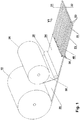
- a soft foam in the form of a wound-up first foam sheet 20 is provided on a first roll 10.
- the soft foam is provided on the first roll 10 in long lengths of up to 200 meters, preferably between 5 and 100 meters, more preferably between 10 and 60 meters.
- foams it is possible to use all known open-cell, mixed-cell or closed-cell flexible foams made of, for example, polyurethane, polyethylene, polyvinyl chloride or polypropylene used, which make a provision after compression.
- the first foam sheet 20 may already be impregnated before further processing, but is preferably not yet impregnated.
- the foam sheet 20 can be particularly well transported and processed.
- the foam web 20 is located on the first roller 10 in an un-compressed or only slightly compressed state. It is also possible for the foam web 20 to be in a compressed state on the first roll 10, but then, after unwinding from the first roll 10, a timely recovery of the foam material in the process flow must be ensured.
- the width of the foam web 20 is usually between 1 cm and 5 m, preferably between 1.0 m and 1.5 m.
- the height of the foam web 20 in the relaxed state is usually between 5 and 150 mm, more preferably between 10 and 80 mm.
- first foam sheets 20 which are not wound on a first roll 10, but which requires a larger supply space.
- the first foam sheet 20 After unwinding from the first roller 10, the first foam sheet 20 is moved along a first conveying direction, which is indicated by the arrow V1. Subsequently, a barrier layer 30 is applied to the top 21 of the first foam sheet 20 so as to form a laminated foam sheet 34.
- the barrier layer 30 is formed by a film web which is provided on a film supply roll 26.
- the barrier layer 30 designed as a film web is preferably applied from above onto the upper side 21 of the foam web 20. This is usually done in the region of a connection unit, which is represented schematically by the roller 28.
- the bonding step typically includes generally a step of applying heat and / or a step of pressing the barrier layer 30 and the foam sheet 20 together.
- the connection to the foam web 20 in the connection unit preferably takes place by lamination.
- the barrier layer 30 can also be formed by a web of a single-sided adhesive tape. The adhesive side of the adhesive tape is then usually provided with a peel-off film, which is peeled off shortly before application to the foam web 20. Likewise, the barrier layer 30 may be formed by a film web which itself comprises a layer of adhesive tape or a solid layer of a hotmelt adhesive. Finally, to form the barrier layer 30, an adhesive-like liquid medium may also be applied to the foam sheet 20 by means of nozzles (e.g., melt die, flat die, mixing die) or by roll coating (transfer roll). Depending on the adhesive may then, preferably in a connection unit, take place a connection with the foam sheet 20, wherein the adhesive is usually solidified.
- nozzles e.g., melt die, flat die, mixing die
- transfer roll e.g., transfer roll
- the connection of the barrier layer 30 to the foam sheet 20 will typically again include a step of applying heat and / or a step of pressing the barrier layer 30 and the foam sheet 20 together. It is also possible to apply a spray adhesive on one side of a film web and to use this combination as a barrier layer 30.
- a skin of the foam material of the first foam sheet 20 itself serve when the foam sheet 20 is melted on one side and then re-hardened or if the foam sheet 20 due to production has a skin.
- Each heat application step above is carried out by means of a heating device, which is usually designed as a hot air blower. But it is also radiant heating in question, for example by means of an infrared heater or microwave heating.
- the function of the barrier layer 30 is preferably to reduce or prevent the passage of air and / or water vapor. This also applies to all subsequent embodiments.
- barrier layer 30 may also be attached to the underside 22 of the foam sheet 20 from below. Another embodiment provides for the application of barrier layers 30 on top 21 and bottom 22 of foam sheet 20.
- At least one blade 38 By means of at least one blade 38, preferably a plurality of parallel blades 38, at least one continuous cut 40, preferably several parallel continuous cuts 40, in the laminated foam sheet 34 in the longitudinal direction of the laminated foam sheet 34, preferably parallel to the longitudinal edges 23 of the laminated foam sheet 34 is introduced ,
- the longitudinal edges 23 are the edges of the laminated foam sheet 34, which are parallel to the conveying direction V1 and orthogonal to the axial direction of the first roller 10.
- all other methods known to those skilled in the art for cutting through foam webs 20 can be used, such as saw cutting, heated wires, laser cutting or water jet cutting.
- the continuous cuts 40 create a plurality of first foam strips 50 provided with a barrier layer 30.
- the first foam strips 50 produced by the at least one cut 40 may have a different width, but they are preferably the same width.
- the width of a foam strip 50 is between 5 mm and 30 cm, preferably between 1 and 12 cm.
- the first foam strips 50 may be wound onto a supply roll (not shown) at this point to enable them to be further processed, thus shortening the length of the entire production line, or may be fed directly to further processing. Overall, the number of successive steps in a production line can be varied by the use of supply rolls as a buffer, and thus the length of the individual sections of the production line can be adjusted according to the prevailing space conditions.
- the first foam sheet 20 is first cut into foam strips 50 and the individual foam strips 50 are then equipped with the barrier layers 30.
- the barrier layers 30 may also extend only over part of a side surface of the foam strips 50.
- a film could be used as a barrier layer 30, which adheres only selectively to the foam strip 50 and thus in the compressed state of the sealing tape an expansion reserve, for example in the form of a loop has.
- a barrier layer 30, for example in the form of a film may be arranged over a plurality of side surfaces.
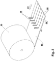
- a second foam web 58 made of soft foam on a second roller 55 is preferably provided uncompressed. After unwinding from the second roller 55, the second foam web 58 is moved along a second conveying direction V2. The same applies to the type of foam as to the foam of the first foam web 20.
- At least one blade 56 By means of at least one blade 56, preferably a plurality of parallel blades 56, at least one continuous cut 59, preferably several parallel continuous cuts 59, is introduced into the second foam web 58 in a direction parallel to the longitudinal edges of the foam web 58.
- the at least one continuous cut 59 thus generates a plurality of second foam strips 60.
- all other methods known to those skilled in the art for cutting foam webs can be used, for example cutting through sawing, heated wires, laser cutting or water jet cutting.
- the second foam strips 60 can be wound up at this point into a supply roll (not shown) or fed directly to further processing.
- the second foam strips 60 may also be provided individually.
- the second foam strips 60, as well as the first foam strips 50 may be provided with at least one barrier layer 30.
- Fig. 3 shows the optional step of impregnating the laminated foam sheet 34 or the first foam strips 50. Impregnation occurs either prior to the step of introducing the at least one cut 40 into the laminated foam sheet 34, or as shown in FIG Fig. 3 shown after the introduction of the at least one continuous section 40 in the laminated foam sheet 34. In the latter case, it is advantageous if the first foam strips 50 are guided in parallel and simultaneously impregnated.
- the impregnation can also take place before the application of the at least one barrier layer 30 to the foam web 20. Due to the poorer adhesion of the barrier layer 30 on an impregnated foam web 20 and thus difficult connecting the barrier layer 30 with the foam sheet 20, however, the impregnation after the application of the barrier layer 30 is preferable.
- the first foam strips 50 are guided side by side through an impregnation unit 90.
- At least two rollers 91 guide the foam strips 50 into a bath of a suitable impregnate 94 and the foam absorbs itself completely with the impregnate.
- Conventional impregnates and methods for impregnating foams are known to the person skilled in the art.
- the foam strips 50 are compressed between the rollers 91 to promote the absorption of the impregnate 94 by the subsequent recovery of the foam.
- excess impregnate is preferably squeezed out by means of rollers.
- the impregnated foam strips 50 are then dried in a drying unit 100.
- the impregnated foam strips 50 are dried in a known manner, for example by a fan heater or radiant heater. Also at this point the subsequent winding on a supply roll or the continuous feed for further processing is possible.
- the optional impregnation of the second foam sheet 58 or the second foam strips 60 comprises the same steps.
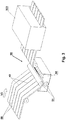
- Fig. 4 shows essential steps of an embodiment of the manufacturing method according to the invention, which is based on the steps Fig. 1 . 2 or 3 can connect.
- the first foam strips 50 provided with at least one barrier layer 30 have already been prefabricated beforehand, for example at another location or by another manufacturer, and within the scope of the inventive method only in this finished form be used.
- a first foam strip 50 and a second foam strip 60 made of soft foam so loosely combined a foam barrier sheeting 70 is formed in which the barrier layer 30 is disposed between the adjoining foam strips 50,60.
- the foam strip 50 is preferably rotated by 90 degrees about its longitudinal axis by means of a suitable deflection device, the longitudinal axis extending along a fourth conveying direction V4.
- the barrier layer 30 is subsequently located on a side surface of the foam strip 50 facing the foam strip 60.
- the first foam strip 50 and the second foam strand 60 are moved together in the conveying direction V4, but are still separated from one another.
- first foam strips 50 may be combined with one or more second foam strips 60, or multiple second foam strips 60 with one or more first foam strips 50.
- the at least one first foam strip 50 may also be provided such that no rotation of the first foam strip 50 is necessary is.
- the at least one second foam strip 60 may be provided such that no rotation of the first foam strip 50 is necessary. It is always important that each provided with a barrier layer 30 side surface of the first foam strip 50 to the adjacent foam strip 50, 60 faces.
- a common tie layer 80 is applied to all of the foam strips 50, 60 of the foam barrier sheeting 70.
- the application of the common bonding layer 80 occurs on a surface of the foam barrier sheeting 70 which is perpendicular to the at least one barrier layer 30.
- the bonding layer 80 is the only strong bond between the foam strips 50, 60 of the foam barrier sheeting 70.
- the tie layer 80 is provided on a supply roll 76 and is applied to the foam barrier sheeting 70 in the region of an application station, here shown schematically by the roll 78, where it is preferably pressed or rolled down.
- Particularly suitable is the use of double-sided adhesive tape as a bonding layer 80.
- This has the advantage that it is easy to apply to the foam barrier layer web 70 and thus at the same time an adhesive surface on the side facing the foam barrier sheeting 70 is provided by means of that's it Sealing tape 2 can be connected during assembly with a frame profile of a window.
- This second adhesive surface of the double-sided adhesive tape on the side facing away from the foam barrier layer web 70 is first laminated with a release liner 81 in order to prevent sticking during further processing.
- the bonding layer 80 it is also possible to use textile fabrics, non-woven fabric layers or other tie-layers which are suitable for joining a plurality of foam strips.
- the connection of the bonding layer 80 to the foam strips 50, 60 preferably takes place by gluing or lamination.
- a sealing tape roll 1 After applying the common bonding layer 80 to all foam strips 50, 60 of the foam barrier sheeting 70, this is compressed to a sealing tape roll 1 wound.
- one or more pairs of compression rollers 84 may be used for the compression.
- a compression roller (not shown) can interact directly with the sealing tape roll when the sealing tape 2 is wound onto the sealing tape roll 1.
- two tie layers 80 may be applied to opposite sides of the foam barrier sheeting 70.
- a foam barrier sheeting 70 is wound from a plurality of foam strips 50, 60 and barrier layers 30 after applying a common tie layer 80 compressed to a wide roll (not shown) that is then joined by at least one knife or at least one knife Saw can be cut to sealing tape rolls 1 desired width.
- the conveying directions V1, V2, V3 and V4 can be identical or different from each other.
- all foam sheets, foam strips or foam barrier sheets are preferably advanced by rolling, more preferably by pairs of counter-rotating rolls. Also treadmills can be used. Such means of locomotion can also be used for the film web or adhesive tape web.
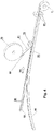
- Fig. 5 shows an installation situation of a sealing tape roll 1 according to Fig. 4 unwound sealing strips 2.
- the sealing strip 2 is first unwind from the sealing strip roll 1 and cut into strips of any length.
- the length of the sealing strip strip is adapted to the outer contours of a sealed window frame or a door frame.
- the sealing tape 2 is then preferably fastened to the window frame 112 or door frame by means of the double-sided adhesive tape acting as a bonding layer 80 or by means of other adhesive layers, adhesive tapes or other suitable means.
- the sealing tape 2 is received between a window frame 112 and masonry 110 to seal the gap between them.
- the illustrated sealing tape 2 in this case comprises a first foam strip 50 provided with a barrier layer 30 and a second foam strip 60.
- the barrier layer 30 is protectively received between the foam strips 50, 60, thereby preventing damage during storage, transportation and storage Assembly of the sealing tape roll 1 and the sealing strip 2 are avoided.
- the sealing strip 2 is to be installed so that at least one barrier layer 30 extends from the window frame 112 to the masonry 110 and thus substantially orthogonal to a functional direction F of the sealing tape 2.
- the functional direction F extends parallel to the surfaces of the window frame 112 and the masonry 110 forming the joint to be sealed from a room outside (in FIG Fig. 5 left) to a room inside (in Fig. 5 right). In this way, a reliable seal against draft and vapor diffusion can be ensured.
- the first foam strip 50 may be made of a different foam material than the second foam strip 60.
- the first foam strips 50 and the second foam strips 60 may be impregnated with different impregnate or only the first foam strips 50 or only the first second foam strip 60 impregnated be.
- the first foam strips 50 may have a different color than the second foam strips 60.
- any number of barrier layers 30 in the sealing tape 2 is possible.
- different widths and / or heights of the first foam strips 50 and / or different widths and / or heights of the second foam strips 60 are conceivable, even within the same sealing strip 2.
- the first or the first foam strips 50 can also have a different width and / or or height than the second foam strip or strips 60.
- the width of the sealing strip 2 is usually between 5 mm and 20 cm, preferably between 1 cm and 12 cm. In the relaxed state, the sealing tape 2 usually has a height of between 5 mm and 30 cm, preferably between 1 and 12 cm.
- FIG. 5 illustrated embodiment forms exactly a first foam strip 50 together with just a second foam strip 60, the foam barrier layer web 70 which is wound into the sealing strip roll 1.
- the foam barrier layer web 70 which is wound into the sealing strip roll 1.
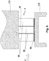
- FIG. 6 Another embodiment is in Fig. 6 shown.
- exactly one first foam strip 50 is brought together with exactly two second foam strips 60 to form the foam barrier web 70, the first foam strip 50 in this case having two barrier layers 30 arranged on opposite sides of the first foam strip 50.
- the first foam strip 50 is disposed between the two second foam strips 60 such that the barrier layers 30 are each disposed between the first foam strip 50 and one of the second foam strips 60.
- the first foam web 20 (FIG. Fig. 1 ) on top 21 and bottom 22 are provided with a barrier layer 30, and then the three foam strips 50, 60 are brought together and bonded together via tie layer 80, similar to FIG Fig. 4 shown.
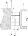
- first foam strips 50 here three first foam strips 50, with exactly one second Foam tabs 60 are joined together to form the foam barrier sheeting 70, with just one barrier layer 30 attached to each first foam strip 50 and with the second foam tab 60 disposed at one edge of the foam barrier sheeting 70.
- the barrier layers 30 are disposed between adjacent foam strips 50, 60.
- the first foam web 20 (FIG. Fig. 1 ) are provided with a barrier layer 30 only on the upper side 21 or the lower side 22, and then the three first foam strips 50 are brought together in a respective 90 ° rotated orientation with the one second foam strip 60 and interconnected via the tie layer 80, similar to FIG Fig. 4 shown.
- foam barrier sheets 70 of any shape can be designed with foam strips 50, 60 and barrier layers 30 preferably alternating in a direction perpendicular to the direction of conveyance V4 and a respective foam strip 50, 60 at one edge of the foam barrier sheet 70 is arranged.
- the connecting layer 80 forms the only connection between the foam strips 50, 60 in the sealing strip 2 and is usually designed as limp, the connecting layer 80 and thus also the sealing strip 2 can be bent at the transition point between individual foam strips 50, 60, which also makes other use variants allows, for example a simultaneous sealing of two joints that abut each other vertically.
- sealing tape 2 between one or all of the foam strips 50, 60 of the sealing tape 2 there may be a small or large gap that is bridged only by the bonding layer 80.
- sealing strips 2 can be realized for relatively wide joints, which require only relatively little material.
- a “barrier layer” 30 is a layer which is suitable for reducing the passage of air or vapor diffusion through the sealing strip 2. A complete blockage against passage of air or over Vapor diffusion is possible, but not necessarily necessary. It may be expedient if at least one barrier layer 30 is moisture-variable in such a way that it is more diffusion-tight at high air humidity than at lower atmospheric humidity or vice versa. With regard to the usable materials for the barrier layer, for example DE 10 2010 055 788 A1 or on EP 2 733 271 A1 directed.
- each barrier layer 30 is permanently elastic, so that it remains permanently elastic even after storage of the sealing strip roll 1 in the compressed state in the return of the sealing strip 2 and in the installed state of the sealing strip 2 in a joint always tight against the joint flanks.
Landscapes
- Engineering & Computer Science (AREA)
- Civil Engineering (AREA)
- Structural Engineering (AREA)
- Architecture (AREA)
- Physics & Mathematics (AREA)
- Electromagnetism (AREA)
- Laminated Bodies (AREA)
Priority Applications (4)
| Application Number | Priority Date | Filing Date | Title |
|---|---|---|---|
| DK14182233.8T DK2990552T3 (en) | 2014-08-26 | 2014-08-26 | Process for manufacturing a sealing tape roller and sealing tape roller |
| EP14182233.8A EP2990552B1 (de) | 2014-08-26 | 2014-08-26 | Verfahren zur herstellung einer dichtbandrolle und dichtbandrolle |
| PL14182233T PL2990552T3 (pl) | 2014-08-26 | 2014-08-26 | Sposób wytwarzania rolki taśmy uszczelniającej i rolka taśmy uszczelniającej |
| HUE14182233A HUE037839T2 (hu) | 2014-08-26 | 2014-08-26 | Eljárás tömítõszalag tekercs elõállítására és tömítõszalag tekercs |
Applications Claiming Priority (1)
| Application Number | Priority Date | Filing Date | Title |
|---|---|---|---|
| EP14182233.8A EP2990552B1 (de) | 2014-08-26 | 2014-08-26 | Verfahren zur herstellung einer dichtbandrolle und dichtbandrolle |
Publications (2)
| Publication Number | Publication Date |
|---|---|
| EP2990552A1 EP2990552A1 (de) | 2016-03-02 |
| EP2990552B1 true EP2990552B1 (de) | 2018-03-21 |
Family
ID=51392147
Family Applications (1)
| Application Number | Title | Priority Date | Filing Date |
|---|---|---|---|
| EP14182233.8A Active EP2990552B1 (de) | 2014-08-26 | 2014-08-26 | Verfahren zur herstellung einer dichtbandrolle und dichtbandrolle |
Country Status (4)
| Country | Link |
|---|---|
| EP (1) | EP2990552B1 (pl) |
| DK (1) | DK2990552T3 (pl) |
| HU (1) | HUE037839T2 (pl) |
| PL (1) | PL2990552T3 (pl) |
Families Citing this family (8)
| Publication number | Priority date | Publication date | Assignee | Title |
|---|---|---|---|---|
| DE102016114227A1 (de) * | 2016-08-01 | 2018-02-01 | Tremco Illbruck Produktion Gmbh | Verfahren und Vorrichtung zum Herstellen eines Dichtbandes |
| DE102017110856A1 (de) * | 2017-05-18 | 2018-12-06 | tremco illbruck GmbH | Herstellungsverfahren für Dichtband und Dichtband |
| PL3453806T5 (pl) * | 2017-09-01 | 2024-01-29 | Iso-Chemie Gmbh | Element uszczelniający |
| DK3567177T3 (da) | 2018-05-07 | 2020-04-06 | Iso Chemie Gmbh | Fremgangsmåde til fremstilling af tætningsbåndruller |
| DE102018118854A1 (de) * | 2018-08-02 | 2020-02-06 | tremco illbruck GmbH | Herstellungsverfahren für Dichtband und Dichtband |
| EP3757306A1 (de) | 2018-11-07 | 2020-12-30 | ISO-Chemie GmbH | Dichtband |
| DE102019127665A1 (de) * | 2019-10-15 | 2021-04-15 | Tremco CPG Germany GmbH | Dichtband zum Abdichten von Bauwerksfugen |
| EP4575114A1 (de) | 2023-12-22 | 2025-06-25 | Hanno-Werk GmbH & Co. KG | Fugendichtungsband |
Citations (14)
| Publication number | Priority date | Publication date | Assignee | Title |
|---|---|---|---|---|
| DE2410121A1 (de) | 1974-03-02 | 1975-09-18 | Irbit Holding Ag | Verfahren zum aufwickeln von platten, streifen oder dergleichen aus elastisch komprimierbarem material |
| EP0229951A2 (de) | 1985-12-14 | 1987-07-29 | Irbit Research + Consulting AG | Dichtungsstreifen |
| US4822655A (en) | 1986-08-08 | 1989-04-18 | Beecham Home Improvements Products Inc. | Butyl rubber preformed tape sealant |
| DE19641415A1 (de) | 1996-10-08 | 1998-04-16 | Hanno Werk Gmbh & Co Kg | Dichtungsband und Verfahren zur Herstellung des Dichtungsbandes |
| EP1473419A2 (de) | 2003-04-29 | 2004-11-03 | ISO-Chemie GmbH | Dichtungsband |
| EP1762377A1 (de) | 2005-09-07 | 2007-03-14 | Alcan Technology & Management Ltd. | Verfahren zur Herstellung eines Laminates |
| EP2107176A1 (de) | 2008-03-31 | 2009-10-07 | ISO-Chemie GmbH | Dichtband aus weichem Schaumstoff |
| DE102009044558A1 (de) | 2008-11-17 | 2010-05-20 | Tremco Illbruck Produktion Gmbh | Verfahren zur Abdichtung einer Bauwerksfuge und Dichtelement |
| DE202010012343U1 (de) | 2009-09-14 | 2010-11-11 | Iso-Chemie Gmbh | Dichtelement |
| EP2354410A2 (de) | 2010-02-09 | 2011-08-10 | Tremco illbruck Produktion GmbH | Schaumstoff-Dichtstreifen und Fensterrahmen mit Schaumstoff-Dichtstreifen |
| DE102010055788A1 (de) | 2010-12-23 | 2012-06-28 | Hanno-Werk Gmbh & Co. Kg | Fugendichtungsband |
| EP2620565A1 (de) | 2012-01-24 | 2013-07-31 | ISO-Chemie GmbH | Dichtband zum Abdichten einer Fuge |
| DE202012101990U1 (de) | 2012-05-23 | 2013-08-27 | Tremco Illbruck Produktion Gmbh | Dichtband |
| EP2743416A2 (de) | 2012-12-12 | 2014-06-18 | Tremco illbruck Produktion GmbH | Dichtband mit Funktionsstreifen |
Family Cites Families (3)
| Publication number | Priority date | Publication date | Assignee | Title |
|---|---|---|---|---|
| DE3133271A1 (de) | 1981-08-22 | 1983-03-03 | Irbit Holding AG, 1701 Fribourg | Zu einer rolle aufgewickelter schaumstoff-streifen, vorzugsweise zu abdichtungszwecken |
| EP1936246B2 (de) | 2006-12-18 | 2013-04-03 | ISO-Chemie GmbH | Dichtband aus Weichschaum und Verfahren zu seiner Herstellung |
| DE202012104454U1 (de) | 2012-11-19 | 2014-02-25 | Tremco Illbruck Produktion Gmbh | Zwangsbelüftetes Gebäude mit Wandaufbau umfassend Dichtungsband |
-
2014
- 2014-08-26 EP EP14182233.8A patent/EP2990552B1/de active Active
- 2014-08-26 PL PL14182233T patent/PL2990552T3/pl unknown
- 2014-08-26 DK DK14182233.8T patent/DK2990552T3/en active
- 2014-08-26 HU HUE14182233A patent/HUE037839T2/hu unknown
Patent Citations (14)
| Publication number | Priority date | Publication date | Assignee | Title |
|---|---|---|---|---|
| DE2410121A1 (de) | 1974-03-02 | 1975-09-18 | Irbit Holding Ag | Verfahren zum aufwickeln von platten, streifen oder dergleichen aus elastisch komprimierbarem material |
| EP0229951A2 (de) | 1985-12-14 | 1987-07-29 | Irbit Research + Consulting AG | Dichtungsstreifen |
| US4822655A (en) | 1986-08-08 | 1989-04-18 | Beecham Home Improvements Products Inc. | Butyl rubber preformed tape sealant |
| DE19641415A1 (de) | 1996-10-08 | 1998-04-16 | Hanno Werk Gmbh & Co Kg | Dichtungsband und Verfahren zur Herstellung des Dichtungsbandes |
| EP1473419A2 (de) | 2003-04-29 | 2004-11-03 | ISO-Chemie GmbH | Dichtungsband |
| EP1762377A1 (de) | 2005-09-07 | 2007-03-14 | Alcan Technology & Management Ltd. | Verfahren zur Herstellung eines Laminates |
| EP2107176A1 (de) | 2008-03-31 | 2009-10-07 | ISO-Chemie GmbH | Dichtband aus weichem Schaumstoff |
| DE102009044558A1 (de) | 2008-11-17 | 2010-05-20 | Tremco Illbruck Produktion Gmbh | Verfahren zur Abdichtung einer Bauwerksfuge und Dichtelement |
| DE202010012343U1 (de) | 2009-09-14 | 2010-11-11 | Iso-Chemie Gmbh | Dichtelement |
| EP2354410A2 (de) | 2010-02-09 | 2011-08-10 | Tremco illbruck Produktion GmbH | Schaumstoff-Dichtstreifen und Fensterrahmen mit Schaumstoff-Dichtstreifen |
| DE102010055788A1 (de) | 2010-12-23 | 2012-06-28 | Hanno-Werk Gmbh & Co. Kg | Fugendichtungsband |
| EP2620565A1 (de) | 2012-01-24 | 2013-07-31 | ISO-Chemie GmbH | Dichtband zum Abdichten einer Fuge |
| DE202012101990U1 (de) | 2012-05-23 | 2013-08-27 | Tremco Illbruck Produktion Gmbh | Dichtband |
| EP2743416A2 (de) | 2012-12-12 | 2014-06-18 | Tremco illbruck Produktion GmbH | Dichtband mit Funktionsstreifen |
Also Published As
| Publication number | Publication date |
|---|---|
| DK2990552T3 (en) | 2018-07-02 |
| PL2990552T3 (pl) | 2018-08-31 |
| HUE037839T2 (hu) | 2018-09-28 |
| EP2990552A1 (de) | 2016-03-02 |
Similar Documents
| Publication | Publication Date | Title |
|---|---|---|
| EP2990552B1 (de) | Verfahren zur herstellung einer dichtbandrolle und dichtbandrolle | |
| EP2990575B1 (de) | Dichtband zum abdichten einer fuge | |
| EP2990551B1 (de) | Verfahren zur Herstellung einer Dichtbandrolle | |
| EP2990553B1 (de) | Verfahren zur herstellung einer dichtbandrolle | |
| EP2620565B1 (de) | Dichtband zum Abdichten einer Fuge | |
| EP3628808B1 (de) | Verfahren zur herstellung eines schaumstoffdichtbandes und schaumstoffdichtband | |
| DE102016114227A1 (de) | Verfahren und Vorrichtung zum Herstellen eines Dichtbandes | |
| EP3450643B2 (de) | Dichtbandrolle | |
| EP3567177B1 (de) | Verfahren zur herstellung von dichtbandrollen | |
| EP3404156B1 (de) | Herstellungsverfahren für dichtband | |
| EP3608482B1 (de) | Verfahren zum herstellen einer dichtbandrolle | |
| EP3650608B1 (de) | Verfahren zum herstellen einer dichtbandrolle | |
| EP3603941B1 (de) | Herstellungsverfahren für dichtband und dichtband | |
| DE102019100686B4 (de) | Verfahren und Vorrichtung zur Herstellung eines Dichtbandes | |
| CH620487A5 (en) | Process and device for producing hollow building blocks | |
| DE102018123811A1 (de) | Verfahren zur Herstellung eines Schaumstoffdichtbandes und Schaumstoffdichtband | |
| DE102018123809A1 (de) | Verfahren zur Herstellung eines Schaumstoffdichtbandes und Schaumstoffdichtband | |
| DE102018127312A1 (de) | Verfahren zur Herstellung eines Schaumstoffdichtbandes und Schaumstoffdichtband | |
| EP2990576A1 (de) | Dichtband zum Abdichten einer Fuge |
Legal Events
| Date | Code | Title | Description |
|---|---|---|---|
| PUAI | Public reference made under article 153(3) epc to a published international application that has entered the european phase |
Free format text: ORIGINAL CODE: 0009012 |
|
| AK | Designated contracting states |
Kind code of ref document: A1 Designated state(s): AL AT BE BG CH CY CZ DE DK EE ES FI FR GB GR HR HU IE IS IT LI LT LU LV MC MK MT NL NO PL PT RO RS SE SI SK SM TR |
|
| AX | Request for extension of the european patent |
Extension state: BA ME |
|
| 17P | Request for examination filed |
Effective date: 20160829 |
|
| RBV | Designated contracting states (corrected) |
Designated state(s): AL AT BE BG CH CY CZ DE DK EE ES FI FR GB GR HR HU IE IS IT LI LT LU LV MC MK MT NL NO PL PT RO RS SE SI SK SM TR |
|
| RIC1 | Information provided on ipc code assigned before grant |
Ipc: E04B 1/68 20060101AFI20170620BHEP Ipc: E06B 1/62 20060101ALI20170620BHEP |
|
| GRAP | Despatch of communication of intention to grant a patent |
Free format text: ORIGINAL CODE: EPIDOSNIGR1 |
|
| STAA | Information on the status of an ep patent application or granted ep patent |
Free format text: STATUS: GRANT OF PATENT IS INTENDED |
|
| INTG | Intention to grant announced |
Effective date: 20170904 |
|
| GRAS | Grant fee paid |
Free format text: ORIGINAL CODE: EPIDOSNIGR3 |
|
| GRAJ | Information related to disapproval of communication of intention to grant by the applicant or resumption of examination proceedings by the epo deleted |
Free format text: ORIGINAL CODE: EPIDOSDIGR1 |
|
| GRAL | Information related to payment of fee for publishing/printing deleted |
Free format text: ORIGINAL CODE: EPIDOSDIGR3 |
|
| STAA | Information on the status of an ep patent application or granted ep patent |
Free format text: STATUS: REQUEST FOR EXAMINATION WAS MADE |
|
| INTC | Intention to grant announced (deleted) | ||
| GRAR | Information related to intention to grant a patent recorded |
Free format text: ORIGINAL CODE: EPIDOSNIGR71 |
|
| STAA | Information on the status of an ep patent application or granted ep patent |
Free format text: STATUS: GRANT OF PATENT IS INTENDED |
|
| GRAA | (expected) grant |
Free format text: ORIGINAL CODE: 0009210 |
|
| STAA | Information on the status of an ep patent application or granted ep patent |
Free format text: STATUS: THE PATENT HAS BEEN GRANTED |
|
| INTG | Intention to grant announced |
Effective date: 20180208 |
|
| AK | Designated contracting states |
Kind code of ref document: B1 Designated state(s): AL AT BE BG CH CY CZ DE DK EE ES FI FR GB GR HR HU IE IS IT LI LT LU LV MC MK MT NL NO PL PT RO RS SE SI SK SM TR |
|
| REG | Reference to a national code |
Ref country code: GB Ref legal event code: FG4D Free format text: NOT ENGLISH |
|
| REG | Reference to a national code |
Ref country code: CH Ref legal event code: EP |
|
| REG | Reference to a national code |
Ref country code: AT Ref legal event code: REF Ref document number: 981255 Country of ref document: AT Kind code of ref document: T Effective date: 20180415 |
|
| REG | Reference to a national code |
Ref country code: IE Ref legal event code: FG4D Free format text: LANGUAGE OF EP DOCUMENT: GERMAN |
|
| REG | Reference to a national code |
Ref country code: DE Ref legal event code: R096 Ref document number: 502014007669 Country of ref document: DE |
|
| REG | Reference to a national code |
Ref country code: RO Ref legal event code: EPE |
|
| REG | Reference to a national code |
Ref country code: NL Ref legal event code: FP |
|
| REG | Reference to a national code |
Ref country code: DK Ref legal event code: T3 Effective date: 20180627 |
|
| REG | Reference to a national code |
Ref country code: SE Ref legal event code: TRGR |
|
| PG25 | Lapsed in a contracting state [announced via postgrant information from national office to epo] |
Ref country code: LT Free format text: LAPSE BECAUSE OF FAILURE TO SUBMIT A TRANSLATION OF THE DESCRIPTION OR TO PAY THE FEE WITHIN THE PRESCRIBED TIME-LIMIT Effective date: 20180321 Ref country code: CY Free format text: LAPSE BECAUSE OF FAILURE TO SUBMIT A TRANSLATION OF THE DESCRIPTION OR TO PAY THE FEE WITHIN THE PRESCRIBED TIME-LIMIT Effective date: 20180321 Ref country code: HR Free format text: LAPSE BECAUSE OF FAILURE TO SUBMIT A TRANSLATION OF THE DESCRIPTION OR TO PAY THE FEE WITHIN THE PRESCRIBED TIME-LIMIT Effective date: 20180321 |
|
| REG | Reference to a national code |
Ref country code: SK Ref legal event code: T3 Ref document number: E 27175 Country of ref document: SK |
|
| REG | Reference to a national code |
Ref country code: LT Ref legal event code: MG4D |
|
| REG | Reference to a national code |
Ref country code: FR Ref legal event code: PLFP Year of fee payment: 5 |
|
| REG | Reference to a national code |
Ref country code: NO Ref legal event code: T2 Effective date: 20180321 |
|
| PG25 | Lapsed in a contracting state [announced via postgrant information from national office to epo] |
Ref country code: LV Free format text: LAPSE BECAUSE OF FAILURE TO SUBMIT A TRANSLATION OF THE DESCRIPTION OR TO PAY THE FEE WITHIN THE PRESCRIBED TIME-LIMIT Effective date: 20180321 Ref country code: RS Free format text: LAPSE BECAUSE OF FAILURE TO SUBMIT A TRANSLATION OF THE DESCRIPTION OR TO PAY THE FEE WITHIN THE PRESCRIBED TIME-LIMIT Effective date: 20180321 Ref country code: BG Free format text: LAPSE BECAUSE OF FAILURE TO SUBMIT A TRANSLATION OF THE DESCRIPTION OR TO PAY THE FEE WITHIN THE PRESCRIBED TIME-LIMIT Effective date: 20180621 |
|
| PG25 | Lapsed in a contracting state [announced via postgrant information from national office to epo] |
Ref country code: MT Free format text: LAPSE BECAUSE OF FAILURE TO SUBMIT A TRANSLATION OF THE DESCRIPTION OR TO PAY THE FEE WITHIN THE PRESCRIBED TIME-LIMIT Effective date: 20180321 |
|
| REG | Reference to a national code |
Ref country code: HU Ref legal event code: AG4A Ref document number: E037839 Country of ref document: HU |
|
| PG25 | Lapsed in a contracting state [announced via postgrant information from national office to epo] |
Ref country code: EE Free format text: LAPSE BECAUSE OF FAILURE TO SUBMIT A TRANSLATION OF THE DESCRIPTION OR TO PAY THE FEE WITHIN THE PRESCRIBED TIME-LIMIT Effective date: 20180321 Ref country code: ES Free format text: LAPSE BECAUSE OF FAILURE TO SUBMIT A TRANSLATION OF THE DESCRIPTION OR TO PAY THE FEE WITHIN THE PRESCRIBED TIME-LIMIT Effective date: 20180321 Ref country code: AL Free format text: LAPSE BECAUSE OF FAILURE TO SUBMIT A TRANSLATION OF THE DESCRIPTION OR TO PAY THE FEE WITHIN THE PRESCRIBED TIME-LIMIT Effective date: 20180321 |
|
| PG25 | Lapsed in a contracting state [announced via postgrant information from national office to epo] |
Ref country code: SM Free format text: LAPSE BECAUSE OF FAILURE TO SUBMIT A TRANSLATION OF THE DESCRIPTION OR TO PAY THE FEE WITHIN THE PRESCRIBED TIME-LIMIT Effective date: 20180321 |
|
| REG | Reference to a national code |
Ref country code: DE Ref legal event code: R026 Ref document number: 502014007669 Country of ref document: DE |
|
| PLBI | Opposition filed |
Free format text: ORIGINAL CODE: 0009260 |
|
| PG25 | Lapsed in a contracting state [announced via postgrant information from national office to epo] |
Ref country code: PT Free format text: LAPSE BECAUSE OF FAILURE TO SUBMIT A TRANSLATION OF THE DESCRIPTION OR TO PAY THE FEE WITHIN THE PRESCRIBED TIME-LIMIT Effective date: 20180723 |
|
| PLAX | Notice of opposition and request to file observation + time limit sent |
Free format text: ORIGINAL CODE: EPIDOSNOBS2 |
|
| 26 | Opposition filed |
Opponent name: TREMCO ILLBRUCK GMBH Effective date: 20181219 |
|
| PG25 | Lapsed in a contracting state [announced via postgrant information from national office to epo] |
Ref country code: MC Free format text: LAPSE BECAUSE OF FAILURE TO SUBMIT A TRANSLATION OF THE DESCRIPTION OR TO PAY THE FEE WITHIN THE PRESCRIBED TIME-LIMIT Effective date: 20180321 |
|
| PG25 | Lapsed in a contracting state [announced via postgrant information from national office to epo] |
Ref country code: LU Free format text: LAPSE BECAUSE OF NON-PAYMENT OF DUE FEES Effective date: 20180826 |
|
| PLBB | Reply of patent proprietor to notice(s) of opposition received |
Free format text: ORIGINAL CODE: EPIDOSNOBS3 |
|
| PG25 | Lapsed in a contracting state [announced via postgrant information from national office to epo] |
Ref country code: SI Free format text: LAPSE BECAUSE OF FAILURE TO SUBMIT A TRANSLATION OF THE DESCRIPTION OR TO PAY THE FEE WITHIN THE PRESCRIBED TIME-LIMIT Effective date: 20180321 |
|
| PG25 | Lapsed in a contracting state [announced via postgrant information from national office to epo] |
Ref country code: TR Free format text: LAPSE BECAUSE OF FAILURE TO SUBMIT A TRANSLATION OF THE DESCRIPTION OR TO PAY THE FEE WITHIN THE PRESCRIBED TIME-LIMIT Effective date: 20180321 |
|
| PG25 | Lapsed in a contracting state [announced via postgrant information from national office to epo] |
Ref country code: GR Free format text: LAPSE BECAUSE OF FAILURE TO SUBMIT A TRANSLATION OF THE DESCRIPTION OR TO PAY THE FEE WITHIN THE PRESCRIBED TIME-LIMIT Effective date: 20180321 Ref country code: MK Free format text: LAPSE BECAUSE OF NON-PAYMENT OF DUE FEES Effective date: 20180321 |
|
| PG25 | Lapsed in a contracting state [announced via postgrant information from national office to epo] |
Ref country code: IS Free format text: LAPSE BECAUSE OF FAILURE TO SUBMIT A TRANSLATION OF THE DESCRIPTION OR TO PAY THE FEE WITHIN THE PRESCRIBED TIME-LIMIT Effective date: 20180721 |
|
| REG | Reference to a national code |
Ref country code: DE Ref legal event code: R100 Ref document number: 502014007669 Country of ref document: DE |
|
| PLCK | Communication despatched that opposition was rejected |
Free format text: ORIGINAL CODE: EPIDOSNREJ1 |
|
| PLBN | Opposition rejected |
Free format text: ORIGINAL CODE: 0009273 |
|
| STAA | Information on the status of an ep patent application or granted ep patent |
Free format text: STATUS: OPPOSITION REJECTED |
|
| 27O | Opposition rejected |
Effective date: 20210331 |
|
| P01 | Opt-out of the competence of the unified patent court (upc) registered |
Effective date: 20230427 |
|
| PGFP | Annual fee paid to national office [announced via postgrant information from national office to epo] |
Ref country code: NL Payment date: 20250826 Year of fee payment: 12 |
|
| PGFP | Annual fee paid to national office [announced via postgrant information from national office to epo] |
Ref country code: HU Payment date: 20250725 Year of fee payment: 12 |
|
| PGFP | Annual fee paid to national office [announced via postgrant information from national office to epo] |
Ref country code: FI Payment date: 20250829 Year of fee payment: 12 |
|
| PGFP | Annual fee paid to national office [announced via postgrant information from national office to epo] |
Ref country code: DE Payment date: 20250826 Year of fee payment: 12 Ref country code: DK Payment date: 20250822 Year of fee payment: 12 |
|
| PGFP | Annual fee paid to national office [announced via postgrant information from national office to epo] |
Ref country code: NO Payment date: 20250829 Year of fee payment: 12 |
|
| PGFP | Annual fee paid to national office [announced via postgrant information from national office to epo] |
Ref country code: PL Payment date: 20250724 Year of fee payment: 12 Ref country code: IT Payment date: 20250827 Year of fee payment: 12 |
|
| PGFP | Annual fee paid to national office [announced via postgrant information from national office to epo] |
Ref country code: BE Payment date: 20250822 Year of fee payment: 12 Ref country code: GB Payment date: 20250827 Year of fee payment: 12 |
|
| PGFP | Annual fee paid to national office [announced via postgrant information from national office to epo] |
Ref country code: FR Payment date: 20250826 Year of fee payment: 12 Ref country code: AT Payment date: 20250822 Year of fee payment: 12 |
|
| PGFP | Annual fee paid to national office [announced via postgrant information from national office to epo] |
Ref country code: CH Payment date: 20250901 Year of fee payment: 12 Ref country code: SE Payment date: 20250827 Year of fee payment: 12 |
|
| PGFP | Annual fee paid to national office [announced via postgrant information from national office to epo] |
Ref country code: CZ Payment date: 20250718 Year of fee payment: 12 Ref country code: IE Payment date: 20250824 Year of fee payment: 12 |
|
| PGFP | Annual fee paid to national office [announced via postgrant information from national office to epo] |
Ref country code: RO Payment date: 20250724 Year of fee payment: 12 |
|
| PGFP | Annual fee paid to national office [announced via postgrant information from national office to epo] |
Ref country code: SK Payment date: 20250718 Year of fee payment: 12 |