EP2990369A1 - Method and arrangement for determining elevator data based on the position of an elevator cabin - Google Patents
Method and arrangement for determining elevator data based on the position of an elevator cabin Download PDFInfo
- Publication number
- EP2990369A1 EP2990369A1 EP14182871.5A EP14182871A EP2990369A1 EP 2990369 A1 EP2990369 A1 EP 2990369A1 EP 14182871 A EP14182871 A EP 14182871A EP 2990369 A1 EP2990369 A1 EP 2990369A1
- Authority
- EP
- European Patent Office
- Prior art keywords
- elevator cabin
- stopping
- elevator
- cabin
- determined
- Prior art date
- Legal status (The legal status is an assumption and is not a legal conclusion. Google has not performed a legal analysis and makes no representation as to the accuracy of the status listed.)
- Withdrawn
Links
- 238000000034 method Methods 0.000 title claims abstract description 24
- 239000003550 marker Substances 0.000 claims abstract description 15
- 239000000725 suspension Substances 0.000 claims abstract description 14
- 229910000831 Steel Inorganic materials 0.000 description 3
- 239000010959 steel Substances 0.000 description 3
- 230000001419 dependent effect Effects 0.000 description 2
- 238000003745 diagnosis Methods 0.000 description 1
- 238000007689 inspection Methods 0.000 description 1
- 238000012423 maintenance Methods 0.000 description 1
- 239000007787 solid Substances 0.000 description 1
- 230000001960 triggered effect Effects 0.000 description 1
Images

Classifications
-
- B—PERFORMING OPERATIONS; TRANSPORTING
- B66—HOISTING; LIFTING; HAULING
- B66B—ELEVATORS; ESCALATORS OR MOVING WALKWAYS
- B66B1/00—Control systems of elevators in general
- B66B1/34—Details, e.g. call counting devices, data transmission from car to control system, devices giving information to the control system
- B66B1/36—Means for stopping the cars, cages, or skips at predetermined levels
- B66B1/44—Means for stopping the cars, cages, or skips at predetermined levels and for taking account of disturbance factors, e.g. variation of load weight
-
- B—PERFORMING OPERATIONS; TRANSPORTING
- B66—HOISTING; LIFTING; HAULING
- B66B—ELEVATORS; ESCALATORS OR MOVING WALKWAYS
- B66B1/00—Control systems of elevators in general
- B66B1/24—Control systems with regulation, i.e. with retroactive action, for influencing travelling speed, acceleration, or deceleration
- B66B1/28—Control systems with regulation, i.e. with retroactive action, for influencing travelling speed, acceleration, or deceleration electrical
-
- B—PERFORMING OPERATIONS; TRANSPORTING
- B66—HOISTING; LIFTING; HAULING
- B66B—ELEVATORS; ESCALATORS OR MOVING WALKWAYS
- B66B1/00—Control systems of elevators in general
- B66B1/34—Details, e.g. call counting devices, data transmission from car to control system, devices giving information to the control system
- B66B1/3492—Position or motion detectors or driving means for the detector
-
- B—PERFORMING OPERATIONS; TRANSPORTING
- B66—HOISTING; LIFTING; HAULING
- B66B—ELEVATORS; ESCALATORS OR MOVING WALKWAYS
- B66B5/00—Applications of checking, fault-correcting, or safety devices in elevators
- B66B5/0006—Monitoring devices or performance analysers
- B66B5/0018—Devices monitoring the operating condition of the elevator system
-
- B—PERFORMING OPERATIONS; TRANSPORTING
- B66—HOISTING; LIFTING; HAULING
- B66B—ELEVATORS; ESCALATORS OR MOVING WALKWAYS
- B66B9/00—Kinds or types of lifts in, or associated with, buildings or other structures
Definitions
- the invention relates to a method and an arrangement for determining elevator data based on the position of an elevator cabin according to the independent claims.
- the position of an elevator cabin in an elevator system is best determined directly using a sensor or encoder which is directly linked to the elevator cabin. This is however expensive since it is necessary to provide a supplementary arrangement for measuring the position of the elevator cabin.
- Another approach is, as described exemplarily in the WO 2012/032020 , to use an incremental rotary encoder connected with a pulley of the elevator system to determine the position of the cabin.
- the cabin when a cabin is reaching stopping at a floor, the cabin may be too fast or too slow. This may impede the rotary encoder of the drive or the control unit of the elevator system to properly control the elevator system and stop the elevator cabin such as the flag reading sensor lies in the middle of the flag marking, as suggested by WO 2012/032020 . This also leads to a stopping inaccuracy of the cabin such that a step is present between the cabin floor and the building floor, said step being e.g. potentially dangerous for passengers of the elevator cabin.
- the method according to the present invention is performed in an elevator system comprising an elevator cabin with a flag reading sensor.
- the elevator cabin is movably arranged in a hoistway and can be moved by a drive over a traction sheave and at least one suspension means along the hoistway can be stopped at a plurality of stopping positions of the hoistway.
- the elevator system can be operated by means of an hydraulic traction means.
- Each stopping position has a flag marker with a known flag height F.
- the movement of the elevator cabin is determined by a control unit connected to an encoder.
- Means for measuring movements of the elevator cabin can be preferably an encoder.
- the encoder is preferably a rotary encoder, in particular an incremental rotary encoder, and is preferably coupled to the traction sheave.
- the travelled distance D of the elevator cabin between the stopping position and the flag edge passed by the flag reading sensor when the elevator cabin is leaving the stopping position for a subsequent ride is measured by the control unit. This is done using the signals of the encoder and the flag reading sensor. Alternatively other door zone sensors may be used instead of said flag reading sensor.
- Door zone markers may be, for example, stripes of reflective tape or magnet bands each having a given height which can be sensed or read by a magnetic sensor.
- the stopping inaccuracy I can be determined by taking into consideration the value F/2-D. With this value or just with the value for D it can be determined whether the stop is over or below the middle of the flag.
- control unit controls the elevator cabin such that it stops with the flag reading sensor in the middle of the flag. If this is not the case, this should be taken into consideration when determining the stopping inaccuracy I. It is further assumed that the spatial relationships between position of the flag markers and the building floor as well as the relationship between flag reading sensor as the preferred door zone sensor, and cabin floor are not variable.
- the measured stopping inaccuracy I is taken into account when stopping the elevator cabin during a further ride.
- the control unit can also continuously monitor the evolution of the stopping inaccuracy (and/or based on the measured travelled distances D) and based on the determined stopping inaccuracies I (and/or based on the measured travelled distances D) determine a drift or slippage of the elevator cabin by taking into account the time interval between car rides. Whether drift issues occur or not can be determined when subsequent trips of the elevator car are done right after the former one.
- Whether slippage issues occur or not can be determined when subsequent trips of the elevator car are done after a long standstill period (e.g. night sleep of the car). So the respective data can be used as an example for determining if the suspension means have reached a maximal allowed stretching over time or after a long standstill period, and/or for determine if slipping of the suspension means occurs. If the slipping exceeds a predefined threshold value, then may be an auto-call of service is triggered.
- Preferred storage means are non-volatile computer storage means such as hard disk drives, solid state drives, memory cards, etc.
- the storage means are not necessarily physically present in the elevator system but may be remote arranged and connected to the control unit via a data connection, such as the internet.
- a possible way to determine whether a drift occurred is to evaluate if the subsequent trip is done right after the former one or the two trips are separated by a long standstill time. By making separate statistics for subsequent trips and trips separated by long time intervals and by analyzing these statistics will allow to decide if the elevator had drifting issues, slippage issues or both.
- the travelled distance D and/or the stopping inaccuracy I of the elevator cabin is determined and stored for every of the plurality of the stopping positions.
- a stopping inaccuracy which may be caused by stretching of the suspension means may be proportional to the length of the suspension means suspending the cabin.
- stretching of the suspension means is more pronounced when the suspension means are long, meaning that the elevator cabin is at a low stopping position.
- the stopping inaccuracy I can therefore be determined for each of the stopping positions such that a correction of the stopping method can be performed for every stopping position separately.
- the travelled distance D and/or the stopping inaccuracy I of the elevator cabin is determined and stored for every direction of travel of the elevator cabin. This takes into account that the travelled distance and/or the stopping inaccuracy at a given stopping position may be different depending of the travelling direction (e.g. upward or downward) of the elevator cabin. Preferably, this is done, as cited above, for each stopping position separately.
- the travelled distance D and/or the stopping inaccuracy I of the elevator cabin is only determined if a load L of the elevator cabin determined by a load sensor is within a given range. Since stopping accuracy may be related to the load L of the elevator cabin, it is useful to compare the stopping inaccuracy only if the load L of the elevator cabin is within a certain range of comparable loads, As an alternative, the stopping inaccuracy I can be determined and stored together with the measured load L in order to allow a correlation between stopping inaccuracy I and load L as well as other factors such speed of the cabin etc. as described above.
- the given load range is calculated according to L ⁇ x, wherein x is a factor dependent on the elevator system, the elevator car and/or the suspension means type.
- the travelled distance D and/or the stopping inaccuracy I of the elevator cabin is only determined if an elevator cabin ride takes place within a given time interval t. Therefore, the method can be used to determine stopping inaccuracy I only if rides of the elevator cabin take place within a short period of time, while if the elevator cabin stands still for long periods, the stopping inaccuracy I is not determined or is not taken into consideration when correcting a stopping method.
- the value for D or for ABS(F/2-D) may be used cabin with an elevator cabin stands still for long periods in order to be able whether drifting occurred or not.
- the invention further solves the problem with an arrangement according to claim 10.
- the arrangement comprises, for example, a flag reading sensor for an elevator cabin, flag markers with a flag height F for every of a plurality of stopping positions of a hoistway and means, typically an encoder, for measuring movement of the elevator cabin.
- the elevator cabin is movably arranged in the hoistway by means of at least one suspension means and a traction sheave coupled with a drive.
- the drive for moving the elevator cabin preferably is coupled to a traction sheave and at least one suspension means
- the arrangement further comprises a control unit for controlling the elevator system connected to an encoder or other means for measuring movements of the elevator cabin.
- the Control unit is able of measuring a travel distance D of the elevator cabin between the stopping position and a flag edge when the elevator cabin is leaving a stopping position by means of the encoder and the flag reading sensor and then can determine a stopping inaccuracy I or an other parameter which refers to the position of an elevator cabin.
- the encoder is a rotary encoder, in particular an incremental rotary encoder, preferably Coupled to the traction sheave.
- control unit is further connected to storage means for storing the determined stopping inaccuracy I.
- control unit is further connected to a load sensor for measuring a load L of the elevator cabin.
- the stopping inaccuracy may be stored in storage means in order to determine changes over time. This can be done taking into consideration other factors such as a direction of travel, a stopping position, a time between rides, a load L of the cabin etc.
- FIG. 1 an elevator system 1 with a hoistway 2 is shown.
- An elevator cabin 3 and a counterweight 4 are movably arranged in the hoistway 2 and connected to each other by means of a suspension means, in this case a steel rope 5.
- the steel rope 5 is conducted over a pulley 6 and a traction sheave 9 connected to an electric motor 8.
- the traction sheave 9 has an incremental rotary encoder 12 connected to it in order to detect movement and of the traction sheave 9 and therefore movement and direction of travel of the elevator cabin 3.
- a control unit 10 is also present and is connected amongst others with the electric motor 8 and the incremental rotary encoder 12.
- a data connection 17 allows remote connection and/or diagnosis of the elevator system 1,
- Each floor 7, 7' and 7" of the hoistway 2 has a building floor 18, which corresponds to a stopping position of the elevator cabin 3. Accordingly, a cabin floor 3.1 of the elevator cabin 3 is aligned with the respective building floor 18 when the elevator cabin 3 is standing still at a floor 7, 7' or 7". In Fig. 1 , the elevator cabin 3 has stopped at floor 7'.
- Every floor building 18 is marked with a flag marker 13 with a flag height F.
- the elevator cabin 3 has a flag reading sensor 15 as a preferred example of a door zone sensor.
- Flag marker 13 and flag reading sensor 15 are arranged with respect to each other such that when the building floor 18 and the cabin floor 3.1 are perfectly aligned, this means that building floor 18 and cabin floor 3.1 are at the same height, the flag reading sensor is positioned exactly in the middle of the flag marker 13. In other words, the distance between the flag reading sensor 15 and a flag edge 14, in this case the lower flag edge, is exactly half of the height F of the flag marker 13.
- control unit 10 can estimate the position of the elevator cabin by means of the incremental rotary encoder 12.
- the flag reading sensor 15 may be used when passing a flag marker 13 to correct or increase the precision of the data from the rotary encoder 19.
- the flag reading sensor 13 When arriving at the desired floor 7', the flag reading sensor 13 detects the flag edge 14 and sends a signal to the control unit 10.
- the control unit 10 uses the rotary encoder 12 and the drive 8 to move the elevator cabin 3 for a further travel of half the height F of the flag marker 13 (F/2), such that the flag reading sensor 15 is exactly positioned in the middle of the flag marker 13 and the building floor 18 and the cabin floor 3.1 are aligned with each other.
- the control unit 10 can determine this stopping inaccuracy in an indirect way when moving the cabin for a further ride.
- the control unit 10 can therefore determine if the cabin was positioned correctly during the last stop or if a step (upward or downward) was present between the building floor 18 and the cabin floor 3.1. In the configuration shown in Fig. 2 , the cabin floor 3.1 would be higher than the building floor 7.
- the determined stopping inaccuracy I is then used to correct a distance/speed profile used to control the elevator cabin in order to increase the stopping precision of the elevator cabin 3.
- the determined stopping inaccuracy is preferably stored in a storage 16 of the control unit 10 and also used to determine if stopping inaccuracy of the elevator system 1 is increasing over time and thus detect a drift of the elevator cabin 3.
- the detected drifting may be then compared with a maximal drifting threshold, whereby if the detected drift is above the threshold, an alarm for a technician requesting inspection or the like may be generated, and sent to a maintenance center over the data connection 17.
- a slippage only values for the travelled distance D and/or the stopping inaccuracy I of the elevator cabin 3 if an elevator cabin ride takes place exceeds a given time interval t two trips are separated by a long standstill time are used or taken into consideration for the determination of the slippage.
- This long time interval t can be 2 hours, preferably 4 hours or most preferably 6 hours (e.g. night steep of the car).
Landscapes
- Engineering & Computer Science (AREA)
- Automation & Control Theory (AREA)
- Computer Networks & Wireless Communication (AREA)
- Structural Engineering (AREA)
- Indicating And Signalling Devices For Elevators (AREA)
Abstract
A method and an arrangement for determining elevator data based on the position of an elevator cabin (3) of an elevator system (1), wherein the elevator cabin (3) has a flag reading sensor (15), is movably arranged in a hoistway (2) and can be moved by a drive (8) over a traction sheave (9) and at least one suspension means (5) an can be stopped at a plurality of stopping positions (18) of the hoistway (2), each stopping position (18) having a flag marker (13) with a flag height (F), and wherein movement of the elevator cabin (3) is determined by a control unit (10) connected to an encoder (12). When leaving a stopping position, the travelled distance (D) of the elevator cabin (3) between the stopping position and a flag edge (14) is measured and a stopping inaccuracy (I) is determined by the control unit (10).
Description
- The invention relates to a method and an arrangement for determining elevator data based on the position of an elevator cabin according to the independent claims.
- The position of an elevator cabin in an elevator system is best determined directly using a sensor or encoder which is directly linked to the elevator cabin. This is however expensive since it is necessary to provide a supplementary arrangement for measuring the position of the elevator cabin.
- Another approach is, as described exemplarily in the
WO 2012/032020 , to use an incremental rotary encoder connected with a pulley of the elevator system to determine the position of the cabin. - This method is not particularly satisfying, since the traction and suspension means of the elevator may stretch over time and due to the loading of the cabin, leading to a drift of the cabin position and consequently to stopping inaccuracy of the cabin. Slipping of the traction means may also cause inaccuracy in the determination of the position of the cabin.
- In addition, when a cabin is reaching stopping at a floor, the cabin may be too fast or too slow. This may impede the rotary encoder of the drive or the control unit of the elevator system to properly control the elevator system and stop the elevator cabin such as the flag reading sensor lies in the middle of the flag marking, as suggested by
WO 2012/032020 . This also leads to a stopping inaccuracy of the cabin such that a step is present between the cabin floor and the building floor, said step being e.g. potentially dangerous for passengers of the elevator cabin. - It is therefore aim of the present invention to provide a method and an arrangement for the determination of elevator data based on the position of an elevator cabin by which stopping inaccuracy, drifting and/or slippage of the elevator cabin may be determined in a reliable way without the need of additional cost and maintenance intensive components.
- The problem is solved with a method and an arrangement according to the independent claims. Dependent claims describe preferred embodiments of the invention.
- The method according to the present invention is performed in an elevator system comprising an elevator cabin with a flag reading sensor. The elevator cabin is movably arranged in a hoistway and can be moved by a drive over a traction sheave and at least one suspension means along the hoistway can be stopped at a plurality of stopping positions of the hoistway. Alternatively, the elevator system can be operated by means of an hydraulic traction means. Each stopping position has a flag marker with a known flag height F. The movement of the elevator cabin is determined by a control unit connected to an encoder.
- Means for measuring movements of the elevator cabin can be preferably an encoder. The encoder is preferably a rotary encoder, in particular an incremental rotary encoder, and is preferably coupled to the traction sheave.
- In order to indirectly determine the stopping inaccuracy at the stopping position, the travelled distance D of the elevator cabin between the stopping position and the flag edge passed by the flag reading sensor when the elevator cabin is leaving the stopping position for a subsequent ride is measured by the control unit. This is done using the signals of the encoder and the flag reading sensor. Alternatively other door zone sensors may be used instead of said flag reading sensor.
- Instead of flag markers other door zone markers are also conceivable, Door zone markers may be, for example, stripes of reflective tape or magnet bands each having a given height which can be sensed or read by a magnetic sensor.
- As a next step, the stopping inaccuracy I can be determined by taking into consideration the value F/2-D. With this value or just with the value for D it can be determined whether the stop is over or below the middle of the flag.
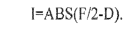
- Preferably, the stopping inaccuracy I is determined according to I=ABS(F/2-D), wherein ABS is the absolute value of the difference between the half of the flag height F and the measured travelled distance D.
- It is assumed that, as cited above, the control unit controls the elevator cabin such that it stops with the flag reading sensor in the middle of the flag. If this is not the case, this should be taken into consideration when determining the stopping inaccuracy I. It is further assumed that the spatial relationships between position of the flag markers and the building floor as well as the relationship between flag reading sensor as the preferred door zone sensor, and cabin floor are not variable.
- Preferably, the measured stopping inaccuracy I is taken into account when stopping the elevator cabin during a further ride.
- This is done preferably by storing the determined stopping inaccuracy I, preferably with other data related to the elevator such as a load of the elevator cabin, the ride path (from the stopping position n to the stopping position m) as well as a time stamp of the ride, in a storage means connected to the control unit. By doing this, the control unit can also continuously monitor the evolution of the stopping inaccuracy (and/or based on the measured travelled distances D) and based on the determined stopping inaccuracies I (and/or based on the measured travelled distances D) determine a drift or slippage of the elevator cabin by taking into account the time interval between car rides. Whether drift issues occur or not can be determined when subsequent trips of the elevator car are done right after the former one. Whether slippage issues occur or not can be determined when subsequent trips of the elevator car are done after a long standstill period (e.g. night sleep of the car). So the respective data can be used as an example for determining if the suspension means have reached a maximal allowed stretching over time or after a long standstill period, and/or for determine if slipping of the suspension means occurs. If the slipping exceeds a predefined threshold value, then may be an auto-call of service is triggered.
- It is therefore furthermore possible to correct the stopping method of the elevator cabin in order to avoid a step between the elevator floor and the building floor. Preferred storage means are non-volatile computer storage means such as hard disk drives, solid state drives, memory cards, etc. The storage means are not necessarily physically present in the elevator system but may be remote arranged and connected to the control unit via a data connection, such as the internet.
- A possible way to determine whether a drift occurred is to evaluate if the subsequent trip is done right after the former one or the two trips are separated by a long standstill time. By making separate statistics for subsequent trips and trips separated by long time intervals and by analyzing these statistics will allow to decide if the elevator had drifting issues, slippage issues or both.
- Preferably, the travelled distance D and/or the stopping inaccuracy I of the elevator cabin is determined and stored for every of the plurality of the stopping positions. This takes into account that a stopping inaccuracy, which may be caused by stretching of the suspension means may be proportional to the length of the suspension means suspending the cabin. In other words, stretching of the suspension means is more pronounced when the suspension means are long, meaning that the elevator cabin is at a low stopping position. The stopping inaccuracy I can therefore be determined for each of the stopping positions such that a correction of the stopping method can be performed for every stopping position separately.
- Preferably, the travelled distance D and/or the stopping inaccuracy I of the elevator cabin is determined and stored for every direction of travel of the elevator cabin. This takes into account that the travelled distance and/or the stopping inaccuracy at a given stopping position may be different depending of the travelling direction (e.g. upward or downward) of the elevator cabin. Preferably, this is done, as cited above, for each stopping position separately.
- Preferably, the travelled distance D and/or the stopping inaccuracy I of the elevator cabin is only determined if a load L of the elevator cabin determined by a load sensor is within a given range. Since stopping accuracy may be related to the load L of the elevator cabin, it is useful to compare the stopping inaccuracy only if the load L of the elevator cabin is within a certain range of comparable loads, As an alternative, the stopping inaccuracy I can be determined and stored together with the measured load L in order to allow a correlation between stopping inaccuracy I and load L as well as other factors such speed of the cabin etc. as described above.
- Preferably, the given load range is calculated according to L ± x, wherein x is a factor dependent on the elevator system, the elevator car and/or the suspension means type. Preferably, the travelled distance D and/or the stopping inaccuracy I of the elevator cabin is only determined if an elevator cabin ride takes place within a given time interval t. Therefore, the method can be used to determine stopping inaccuracy I only if rides of the elevator cabin take place within a short period of time, while if the elevator cabin stands still for long periods, the stopping inaccuracy I is not determined or is not taken into consideration when correcting a stopping method. However, the value for D or for ABS(F/2-D) may be used cabin with an elevator cabin stands still for long periods in order to be able whether drifting occurred or not. By making separate statistics for subsequent trips and trips separated by long time and by analyzing these statistics will allow to decide if the elevator has drifting issues, slippage issues or both.
- The invention further solves the problem with an arrangement according to claim 10.
- The arrangement comprises, for example, a flag reading sensor for an elevator cabin, flag markers with a flag height F for every of a plurality of stopping positions of a hoistway and means, typically an encoder, for measuring movement of the elevator cabin. The elevator cabin is movably arranged in the hoistway by means of at least one suspension means and a traction sheave coupled with a drive. The drive for moving the elevator cabin preferably is coupled to a traction sheave and at least one suspension means The arrangement further comprises a control unit for controlling the elevator system connected to an encoder or other means for measuring movements of the elevator cabin. The Control unit is able of measuring a travel distance D of the elevator cabin between the stopping position and a flag edge when the elevator cabin is leaving a stopping position by means of the encoder and the flag reading sensor and then can determine a stopping inaccuracy I or an other parameter which refers to the position of an elevator cabin.
- Preferably, the stopping inaccuracy is determined according to I=ABS(F/2-D), wherein ABS is the absolute value of the difference between the half of the flag height F and the measured travelled distance D.
- A method as cited above is preferably used with the arrangement according to the present invention. Preferably, the encoder is a rotary encoder, in particular an incremental rotary encoder, preferably Coupled to the traction sheave.
- It is therefore possible to provide an accurate determination of stopping inaccuracy without the need of means for determining the position of the elevator cabin directly (e.g. without the need of a position encoder on the elevator cabin).
- Preferably, the control unit is further connected to storage means for storing the determined stopping inaccuracy I.
- Preferably, the control unit is further connected to a load sensor for measuring a load L of the elevator cabin.
- As cited above regarding the method, the stopping inaccuracy may be stored in storage means in order to determine changes over time. This can be done taking into consideration other factors such as a direction of travel, a stopping position, a time between rides, a load L of the cabin etc.
- Further advantages of the invention will be better understood with the aid of the following description together with the Figures. It is shown in
-
Fig. 1 a schematical view of an elevator system; -
Fig. 1A a detailed view of the detail A ofFigure 1 ; -
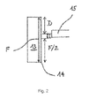
Fig. 2 a schematical view of the detail A ofFigure 1 . - In
Fig. 1 anelevator system 1 with ahoistway 2 is shown. Anelevator cabin 3 and a counterweight 4 are movably arranged in thehoistway 2 and connected to each other by means of a suspension means, in this case asteel rope 5. Thesteel rope 5 is conducted over apulley 6 and a traction sheave 9 connected to an electric motor 8. The traction sheave 9 has anincremental rotary encoder 12 connected to it in order to detect movement and of the traction sheave 9 and therefore movement and direction of travel of theelevator cabin 3. - A control unit 10 is also present and is connected amongst others with the electric motor 8 and the incremental
rotary encoder 12. Adata connection 17 allows remote connection and/or diagnosis of theelevator system 1, - Each
floor hoistway 2 has abuilding floor 18, which corresponds to a stopping position of theelevator cabin 3. Accordingly, a cabin floor 3.1 of theelevator cabin 3 is aligned with therespective building floor 18 when theelevator cabin 3 is standing still at afloor Fig. 1 , theelevator cabin 3 has stopped at floor 7'. - In order to correctly stop the cabin at the desired floor 7', every floor building 18 is marked with a flag marker 13 with a flag height F. However, it would also be conceivable to use other door zone markers or other markers in the hoistway. The
elevator cabin 3 has aflag reading sensor 15 as a preferred example of a door zone sensor. Flag marker 13 andflag reading sensor 15 are arranged with respect to each other such that when thebuilding floor 18 and the cabin floor 3.1 are perfectly aligned, this means that buildingfloor 18 and cabin floor 3.1 are at the same height, the flag reading sensor is positioned exactly in the middle of the flag marker 13. In other words, the distance between theflag reading sensor 15 and aflag edge 14, in this case the lower flag edge, is exactly half of the height F of the flag marker 13. - When an
elevator cabin 3 is moving to the desired floor 7', e.g. moving upwards, the control unit 10 can estimate the position of the elevator cabin by means of the incrementalrotary encoder 12. - In addition, the
flag reading sensor 15 may be used when passing a flag marker 13 to correct or increase the precision of the data from the rotary encoder 19. - When arriving at the desired floor 7', the flag reading sensor 13 detects the
flag edge 14 and sends a signal to the control unit 10. The control unit 10 uses therotary encoder 12 and the drive 8 to move theelevator cabin 3 for a further travel of half the height F of the flag marker 13 (F/2), such that theflag reading sensor 15 is exactly positioned in the middle of the flag marker 13 and thebuilding floor 18 and the cabin floor 3.1 are aligned with each other. - It is however possible that due to slipping or stretching of the
steel rope 5 or due to wrong speed of theelevator cabin 3, that stopping does not occur at the desired stopping position. Such a case is schematically shown inFig. 2 . - The control unit 10 can determine this stopping inaccuracy in an indirect way when moving the cabin for a further ride.
- If the
elevator cabin 3 is moved upward within a given time gap t from the last ride, and the load L of theelevator cabin 3, measured by means of aload sensor 11, is within a given range L ± x, the travelled distance D from start until the detected end of the flag marker 13 (in this case the upper flag edge) is measured by means of therotary encoder 12. A stopping inaccuracy I is then determined according to I=(F/2-D). Taking into account the direction of travel of theelevator cabin 3, the control unit 10 can therefore determine if the cabin was positioned correctly during the last stop or if a step (upward or downward) was present between thebuilding floor 18 and the cabin floor 3.1. In the configuration shown inFig. 2 , the cabin floor 3.1 would be higher than thebuilding floor 7. - The determined stopping inaccuracy I is then used to correct a distance/speed profile used to control the elevator cabin in order to increase the stopping precision of the
elevator cabin 3. - The determined stopping inaccuracy is preferably stored in a storage 16 of the control unit 10 and also used to determine if stopping inaccuracy of the
elevator system 1 is increasing over time and thus detect a drift of theelevator cabin 3. The detected drifting may be then compared with a maximal drifting threshold, whereby if the detected drift is above the threshold, an alarm for a technician requesting inspection or the like may be generated, and sent to a maintenance center over thedata connection 17. For determining a slippage only values for the travelled distance D and/or the stopping inaccuracy I of theelevator cabin 3 if an elevator cabin ride takes place exceeds a given time interval t two trips are separated by a long standstill time are used or taken into consideration for the determination of the slippage. This long time interval t can be 2 hours, preferably 4 hours or most preferably 6 hours (e.g. night steep of the car).
Claims (15)
- Method for determining elevator data based on a position of an elevator cabin (3) of an elevator system (1), wherein the elevator cabin (3) has a door zone sensor (15) and is movably arranged in a hoistway (2) and the elevator cabin (3) can be moved by a drive (8) over a traction sheave (9) and via at least one suspension means (5) and can be stopped at a plurality of stopping positions (18) of the hoistway (2), each stopping position (18) having a door zone marker (13) with a given height (F), and wherein movement of the elevator cabin (3) is determined by a control unit (10) connected to an encoder (12), characterized in that, when the elevator cabin (3) is leaving a stopping position, the travelled distance (D) of the elevator cabin (3) between the stopping position and an edge of the door zone marker is measured and at least one actual position parameter (I) based on the travelled distance (D) and the height (F) of the door zone marker is determined by the control unit (10).
- Method according to claim 1, characterized in that the actual position parameter is the stopping inaccuracy (I) which is determined according to
- Method according to claim 1 or 3, characterized in that the determined stopping inaccuracy (I) is taken into account when controlling the next stop of the elevator cabin (3).
- Method according to one of the preceding claims, characterized in that the measured various travelled distances (D) and/or the determined stopping inaccuracies (I) over time are stored in a storage means (16) connected to the control unit (10) for determining a drift or slippage of the elevator cabin (3) over time.
- Method according to claim 4, characterized in that the travelled distance (D) and/or stopping inaccuracy (1) of the elevator cabin (3) is determined and stored for each of the plurality of the stopping positions (18).
- Method according to claim 4 or 5, characterized in that the travelled distance (D) and/or the stopping inaccuracy (I) of the elevator cabin (3) is determined and stored for every direction of travel of the elevator cabin (3).
- Method according to one of the preceding claims, characterized that the travelled distance (D) and/or the stopping inaccuracy (I) of the elevator cabin (3) is only determined if a load (L) of the elevator cabin determined by a load sensor (11) is within a given range.
- Method according to one of the claims 1 to 7, characterized in that for determining the drifting the travelled distance (D) and/or the stopping inaccuracy (I) of the elevator cabin (3) is only determined if an elevator cabin ride takes place within a given time interval (t).
- Method according to one of the claims 1 to 7, characterized that for determining the slippage the travelled distance (D) and/or the stopping inaccuracy (I) of the elevator cabin (3) is only determined if an elevator cabin ride takes place exceeds a given time interval (t).
- Arrangement for determining elevator data based on a position of an elevator cabin (3) of an elevator system (1), preferably according to a method of one of the preceding claims, comprising a door zone sensor (15) for the elevator cabin (3), door zone markers (13) with a given height (F) for at least one, preferably every of a plurality of stopping positions (18) within a hoistway (2) and means for measuring movements of the elevator cabin (3), a drive (8) for moving the elevator cabin (3) and a control unit (10) for controlling the elevator system (1), characterized in that the control unit (10) is capable of measuring a travel distance (D) of the elevator cabin (3) between a first stopping position (18) and an edge of the door zone marker (14) when the elevator cabin (3) is leaving the stopping position (18) by means (12) for measuring movements of the elevator cabin and for determining a stopping inaccuracy (I) or another position parameter based on the travelled distance (D) and the height (F) of the door zone marker.
- Arrangement according to claim 10, characterized in that the control unit (10) is able to determine the stopping inaccuracy (I) as the actual position parameter whereas the stopping inaccuracy (I) is determined according to

- Arrangement according to claim 10 or 11, characterized in that the control unit (10) is further connected to storage means (16) for the determined stopping inaccuracy (I).
- Arrangement according to one of the claims 10 to 12, characterized in that the control unit (10) is further connected to a load sensor (11) for measuring a load (L) of the elevator cabin (3).
- Arrangement according one of the claims 10 to 13, characterized in that the means for measuring movements of the elevator cabin is a rotary encoder (12), in particular an incremental rotary encoder, preferably coupled to the traction sheave (9).
- Elevator system on which the method according to one of the claims 1 to 9 can be executed and/or with an arrangement according to one of the claims 10 to 14.
Priority Applications (7)
| Application Number | Priority Date | Filing Date | Title |
|---|---|---|---|
| EP14182871.5A EP2990369A1 (en) | 2014-08-29 | 2014-08-29 | Method and arrangement for determining elevator data based on the position of an elevator cabin |
| CN201580044944.1A CN106573752B (en) | 2014-08-29 | 2015-08-27 | Method and apparatus for determining elevator data based on the position of an elevator car |
| US15/506,764 US10556774B2 (en) | 2014-08-29 | 2015-08-27 | Method and arrangement for determining elevator data based on the position of an elevator car |
| EP15760423.2A EP3186182A1 (en) | 2014-08-29 | 2015-08-27 | Method and arrangement for determining elevator data based on the position of an elevator cabin |
| PCT/EP2015/069702 WO2016030487A1 (en) | 2014-08-29 | 2015-08-27 | Method and arrangement for determining elevator data based on the position of an elevator cabin |
| CA2956175A CA2956175A1 (en) | 2014-08-29 | 2015-08-27 | Method and arrangement for determining elevator data based on the position of an elevator cabin |
| CONC2017/0002326A CO2017002326A2 (en) | 2014-08-29 | 2017-03-09 | Method and system for determining elevator data based on the position of an elevator car |
Applications Claiming Priority (1)
| Application Number | Priority Date | Filing Date | Title |
|---|---|---|---|
| EP14182871.5A EP2990369A1 (en) | 2014-08-29 | 2014-08-29 | Method and arrangement for determining elevator data based on the position of an elevator cabin |
Publications (1)
| Publication Number | Publication Date |
|---|---|
| EP2990369A1 true EP2990369A1 (en) | 2016-03-02 |
Family
ID=51421979
Family Applications (2)
| Application Number | Title | Priority Date | Filing Date |
|---|---|---|---|
| EP14182871.5A Withdrawn EP2990369A1 (en) | 2014-08-29 | 2014-08-29 | Method and arrangement for determining elevator data based on the position of an elevator cabin |
| EP15760423.2A Withdrawn EP3186182A1 (en) | 2014-08-29 | 2015-08-27 | Method and arrangement for determining elevator data based on the position of an elevator cabin |
Family Applications After (1)
| Application Number | Title | Priority Date | Filing Date |
|---|---|---|---|
| EP15760423.2A Withdrawn EP3186182A1 (en) | 2014-08-29 | 2015-08-27 | Method and arrangement for determining elevator data based on the position of an elevator cabin |
Country Status (6)
| Country | Link |
|---|---|
| US (1) | US10556774B2 (en) |
| EP (2) | EP2990369A1 (en) |
| CN (1) | CN106573752B (en) |
| CA (1) | CA2956175A1 (en) |
| CO (1) | CO2017002326A2 (en) |
| WO (1) | WO2016030487A1 (en) |
Cited By (1)
| Publication number | Priority date | Publication date | Assignee | Title |
|---|---|---|---|---|
| EP3401262A1 (en) * | 2017-05-12 | 2018-11-14 | Otis Elevator Company | Automatic elevator inspection and positioning systems and methods |
Families Citing this family (13)
| Publication number | Priority date | Publication date | Assignee | Title |
|---|---|---|---|---|
| US10968075B2 (en) * | 2015-06-30 | 2021-04-06 | Otis Elevator Company | Elevator car location zones in hoistway |
| KR102135192B1 (en) * | 2016-07-20 | 2020-07-17 | 미쓰비시덴키 가부시키가이샤 | Elevator control device and control method |
| US10981750B2 (en) * | 2016-09-23 | 2021-04-20 | Otis Elevator Company | Prognostic analysis of elevator performance using sensors and internet of things |
| US20190382234A1 (en) * | 2018-06-19 | 2019-12-19 | Otis Elevator Company | Position reference device for elevator |
| EP3896021A4 (en) * | 2018-12-14 | 2022-07-27 | Hitachi, Ltd. | ELEVATOR CONTROL DEVICE |
| WO2020126429A1 (en) * | 2018-12-18 | 2020-06-25 | Inventio Ag | Elevator system having a laser distance-measuring device |
| US11649136B2 (en) * | 2019-02-04 | 2023-05-16 | Otis Elevator Company | Conveyance apparatus location determination using probability |
| CN112345363B (en) * | 2019-08-06 | 2023-12-19 | 明门(中国)幼童用品有限公司 | Cable performance measuring equipment |
| EP3915911B1 (en) * | 2020-05-27 | 2024-07-17 | KONE Corporation | Movement evaluation method for an elevator car |
| WO2022129208A1 (en) * | 2020-12-16 | 2022-06-23 | Inventio Ag | Method and controller for determining information about a current location of a cabin in a shaft of an elevator |
| CN117355474A (en) * | 2021-04-30 | 2024-01-05 | 因温特奥股份公司 | Elevator equipment |
| US20220396921A1 (en) * | 2021-06-09 | 2022-12-15 | Frank Asamoah Frimpong | Freestanding kojo helipad for vtol flying cars |
| CN116202398B (en) * | 2023-05-06 | 2023-07-21 | 蒂升电梯(中国)有限公司成都分公司 | An elevator installation gap measuring device |
Citations (3)
| Publication number | Priority date | Publication date | Assignee | Title |
|---|---|---|---|---|
| GB2255246A (en) * | 1991-04-22 | 1992-10-28 | Hitachi Ltd | Elevator system |
| US6026935A (en) * | 1996-12-30 | 2000-02-22 | Lg Industrial Systems Co., Ltd. | Cage stop height readjusting apparatus for elevator system and method thereof |
| WO2012032020A1 (en) | 2010-09-09 | 2012-03-15 | Inventio Ag | Method for controlling a drive motor of a lift system |
Family Cites Families (18)
| Publication number | Priority date | Publication date | Assignee | Title |
|---|---|---|---|---|
| US4245721A (en) | 1978-12-18 | 1981-01-20 | Otis Elevator Company | Floor distance sensor for an elevator car |
| JPS6054227B2 (en) * | 1979-05-11 | 1985-11-29 | 株式会社日立製作所 | AC elevator control device |
| US5631452A (en) * | 1994-08-18 | 1997-05-20 | Otis Elevator Company | System for position loss recovery for an elevator car |
| US5659159A (en) * | 1994-12-16 | 1997-08-19 | Otis Elevator Company | Elevator level control system using elevator/landing gap as a reflection duct |
| JP3268483B2 (en) * | 1995-05-16 | 2002-03-25 | 株式会社日立製作所 | Elevator control device |
| US5783783A (en) * | 1995-10-05 | 1998-07-21 | Otis Elevator Company | Correction run for an elevator system |
| US5747755A (en) * | 1995-12-22 | 1998-05-05 | Otis Elevator Company | Elevator position compensation system |
| US5677519A (en) * | 1996-02-29 | 1997-10-14 | Otis Elevator Company | Elevator leveling adjustment |
| JPH10139295A (en) * | 1996-11-07 | 1998-05-26 | Nippon Otis Elevator Co | Elevator control device |
| KR100259511B1 (en) | 1998-03-26 | 2000-07-01 | 이종수 | Elevator position control method |
| US6526368B1 (en) * | 2000-03-16 | 2003-02-25 | Otis Elevator Company | Elevator car position sensing system |
| US6435315B1 (en) * | 2000-12-11 | 2002-08-20 | Otis Elevator Company | Absolute position reference system for an elevator |
| US6488128B1 (en) * | 2000-12-12 | 2002-12-03 | Otis Elevator Company | Integrated shaft sensor for load measurement and torque control in elevators and escalators |
| JP2004075235A (en) * | 2002-08-12 | 2004-03-11 | Toshiba Elevator Co Ltd | Balancing compensation device for elevator car |
| JP2004175538A (en) * | 2002-11-28 | 2004-06-24 | Toshiba Elevator Co Ltd | Elevator control device |
| JP4907533B2 (en) * | 2004-08-10 | 2012-03-28 | オーチス エレベータ カンパニー | Elevator car positioning system |
| JP5354575B2 (en) * | 2008-11-12 | 2013-11-27 | 東芝エレベータ株式会社 | Elevator and elevator control method |
| JP6008995B2 (en) * | 2013-01-23 | 2016-10-19 | 三菱電機株式会社 | Elevator equipment |
-
2014
- 2014-08-29 EP EP14182871.5A patent/EP2990369A1/en not_active Withdrawn
-
2015
- 2015-08-27 EP EP15760423.2A patent/EP3186182A1/en not_active Withdrawn
- 2015-08-27 CA CA2956175A patent/CA2956175A1/en not_active Abandoned
- 2015-08-27 US US15/506,764 patent/US10556774B2/en active Active
- 2015-08-27 WO PCT/EP2015/069702 patent/WO2016030487A1/en not_active Ceased
- 2015-08-27 CN CN201580044944.1A patent/CN106573752B/en active Active
-
2017
- 2017-03-09 CO CONC2017/0002326A patent/CO2017002326A2/en unknown
Patent Citations (3)
| Publication number | Priority date | Publication date | Assignee | Title |
|---|---|---|---|---|
| GB2255246A (en) * | 1991-04-22 | 1992-10-28 | Hitachi Ltd | Elevator system |
| US6026935A (en) * | 1996-12-30 | 2000-02-22 | Lg Industrial Systems Co., Ltd. | Cage stop height readjusting apparatus for elevator system and method thereof |
| WO2012032020A1 (en) | 2010-09-09 | 2012-03-15 | Inventio Ag | Method for controlling a drive motor of a lift system |
Cited By (3)
| Publication number | Priority date | Publication date | Assignee | Title |
|---|---|---|---|---|
| EP3401262A1 (en) * | 2017-05-12 | 2018-11-14 | Otis Elevator Company | Automatic elevator inspection and positioning systems and methods |
| US10577222B2 (en) | 2017-05-12 | 2020-03-03 | Otis Elevator Company | Coded elevator inspection and positioning systems and methods |
| AU2018203299B2 (en) * | 2017-05-12 | 2023-09-07 | Otis Elevator Company | Automatic elevator inspection and positioning systems and methods |
Also Published As
| Publication number | Publication date |
|---|---|
| CA2956175A1 (en) | 2016-03-03 |
| EP3186182A1 (en) | 2017-07-05 |
| WO2016030487A1 (en) | 2016-03-03 |
| CO2017002326A2 (en) | 2017-05-19 |
| US20170253461A1 (en) | 2017-09-07 |
| CN106573752A (en) | 2017-04-19 |
| US10556774B2 (en) | 2020-02-11 |
| CN106573752B (en) | 2019-01-29 |
Similar Documents
| Publication | Publication Date | Title |
|---|---|---|
| US10556774B2 (en) | Method and arrangement for determining elevator data based on the position of an elevator car | |
| JP4907533B2 (en) | Elevator car positioning system | |
| JP6167885B2 (en) | Method for adjusting elevator car position detection device | |
| EP2925653B1 (en) | Position recovery via dummy landing patterns | |
| CN104936879B (en) | Elevator device | |
| EP3081519B1 (en) | Method for the position detection of an elevator car | |
| US20220297977A1 (en) | Elevator safety system | |
| US8439167B2 (en) | Spacing control for two elevator cars in a common shaft | |
| US12421081B2 (en) | Method and an elevator system for defining an elongation of an elevator car suspension device | |
| CN105752782B (en) | The supervising device and monitoring method of lift car | |
| CN108408544B (en) | Method for defining absolute positioning information of an elevator car, safety control unit and elevator system | |
| US10266371B2 (en) | Elevator control apparatus | |
| CN111942995A (en) | Elevator rope inspection system | |
| EP3663248B1 (en) | Device and method for monitoring an elevator system | |
| JP2015140240A5 (en) | ||
| CN114206759B (en) | Method and device for determining the current precise position of an elevator car in an elevator shaft | |
| KR20150003476U (en) | Position detecting system of elevator car using by laser sensor | |
| CN113493149A (en) | Elevator safety system | |
| EP2765109A2 (en) | Control system of the position, speed limit and uncontrolled movements of the cabin or counterweight of an elevator | |
| CN109956375B (en) | Elevator control device and elevator control method | |
| EP3653555B1 (en) | Elevator arrangement and method | |
| JP2006306581A (en) | Elevator main rope slip detection device | |
| HK1258237B (en) | A method, a safety control unit and an elevator system for defining absolute position information of an elevator car | |
| JP2012096871A (en) | Elevator device | |
| HK1189870B (en) | Lift facility, marking device and measuring device |
Legal Events
| Date | Code | Title | Description |
|---|---|---|---|
| PUAI | Public reference made under article 153(3) epc to a published international application that has entered the european phase |
Free format text: ORIGINAL CODE: 0009012 |
|
| AK | Designated contracting states |
Kind code of ref document: A1 Designated state(s): AL AT BE BG CH CY CZ DE DK EE ES FI FR GB GR HR HU IE IS IT LI LT LU LV MC MK MT NL NO PL PT RO RS SE SI SK SM TR |
|
| AX | Request for extension of the european patent |
Extension state: BA ME |
|
| STAA | Information on the status of an ep patent application or granted ep patent |
Free format text: STATUS: THE APPLICATION IS DEEMED TO BE WITHDRAWN |
|
| 18D | Application deemed to be withdrawn |
Effective date: 20160903 |