EP2989886B1 - Improvements in domestic greenhouses - Google Patents
Improvements in domestic greenhouses Download PDFInfo
- Publication number
- EP2989886B1 EP2989886B1 EP15183382.9A EP15183382A EP2989886B1 EP 2989886 B1 EP2989886 B1 EP 2989886B1 EP 15183382 A EP15183382 A EP 15183382A EP 2989886 B1 EP2989886 B1 EP 2989886B1
- Authority
- EP
- European Patent Office
- Prior art keywords
- door
- greenhouse
- secured
- support assembly
- telescopic
- Prior art date
- Legal status (The legal status is an assumption and is not a legal conclusion. Google has not performed a legal analysis and makes no representation as to the accuracy of the status listed.)
- Active
Links
- 230000000712 assembly Effects 0.000 claims description 10
- 238000000429 assembly Methods 0.000 claims description 10
- 230000000717 retained effect Effects 0.000 claims description 4
- 239000004411 aluminium Substances 0.000 description 5
- 229910052782 aluminium Inorganic materials 0.000 description 5
- XAGFODPZIPBFFR-UHFFFAOYSA-N aluminium Chemical compound [Al] XAGFODPZIPBFFR-UHFFFAOYSA-N 0.000 description 5
- 239000011521 glass Substances 0.000 description 5
- 238000001125 extrusion Methods 0.000 description 4
- 229910052751 metal Inorganic materials 0.000 description 3
- 239000002184 metal Substances 0.000 description 3
- 230000000694 effects Effects 0.000 description 2
- 230000004048 modification Effects 0.000 description 2
- 238000012986 modification Methods 0.000 description 2
- 230000002349 favourable effect Effects 0.000 description 1
- 238000004519 manufacturing process Methods 0.000 description 1
- 239000000463 material Substances 0.000 description 1
- 239000002023 wood Substances 0.000 description 1
Images


Classifications
-
- A—HUMAN NECESSITIES
- A01—AGRICULTURE; FORESTRY; ANIMAL HUSBANDRY; HUNTING; TRAPPING; FISHING
- A01G—HORTICULTURE; CULTIVATION OF VEGETABLES, FLOWERS, RICE, FRUIT, VINES, HOPS OR SEAWEED; FORESTRY; WATERING
- A01G9/00—Cultivation in receptacles, forcing-frames or greenhouses; Edging for beds, lawn or the like
- A01G9/14—Greenhouses
-
- E—FIXED CONSTRUCTIONS
- E05—LOCKS; KEYS; WINDOW OR DOOR FITTINGS; SAFES
- E05D—HINGES OR SUSPENSION DEVICES FOR DOORS, WINDOWS OR WINGS
- E05D15/00—Suspension arrangements for wings
- E05D15/06—Suspension arrangements for wings for wings sliding horizontally more or less in their own plane
- E05D15/0621—Details, e.g. suspension or supporting guides
-
- E—FIXED CONSTRUCTIONS
- E05—LOCKS; KEYS; WINDOW OR DOOR FITTINGS; SAFES
- E05D—HINGES OR SUSPENSION DEVICES FOR DOORS, WINDOWS OR WINGS
- E05D15/00—Suspension arrangements for wings
- E05D15/06—Suspension arrangements for wings for wings sliding horizontally more or less in their own plane
- E05D15/08—Suspension arrangements for wings for wings sliding horizontally more or less in their own plane consisting of two or more independent parts movable each in its own guides
-
- E—FIXED CONSTRUCTIONS
- E05—LOCKS; KEYS; WINDOW OR DOOR FITTINGS; SAFES
- E05D—HINGES OR SUSPENSION DEVICES FOR DOORS, WINDOWS OR WINGS
- E05D15/00—Suspension arrangements for wings
- E05D15/06—Suspension arrangements for wings for wings sliding horizontally more or less in their own plane
- E05D15/14—Suspension arrangements for wings for wings sliding horizontally more or less in their own plane with movable arms situated in the plane of the wing
-
- E—FIXED CONSTRUCTIONS
- E06—DOORS, WINDOWS, SHUTTERS, OR ROLLER BLINDS IN GENERAL; LADDERS
- E06B—FIXED OR MOVABLE CLOSURES FOR OPENINGS IN BUILDINGS, VEHICLES, FENCES OR LIKE ENCLOSURES IN GENERAL, e.g. DOORS, WINDOWS, BLINDS, GATES
- E06B3/00—Window sashes, door leaves, or like elements for closing wall or like openings; Layout of fixed or moving closures, e.g. windows in wall or like openings; Features of rigidly-mounted outer frames relating to the mounting of wing frames
- E06B3/92—Doors or windows extensible when set in position
- E06B3/921—Doors or windows extensible when set in position with several parts mounted telescopically inside each other
-
- A—HUMAN NECESSITIES
- A01—AGRICULTURE; FORESTRY; ANIMAL HUSBANDRY; HUNTING; TRAPPING; FISHING
- A01G—HORTICULTURE; CULTIVATION OF VEGETABLES, FLOWERS, RICE, FRUIT, VINES, HOPS OR SEAWEED; FORESTRY; WATERING
- A01G9/00—Cultivation in receptacles, forcing-frames or greenhouses; Edging for beds, lawn or the like
- A01G9/24—Devices or systems for heating, ventilating, regulating temperature, illuminating, or watering, in greenhouses, forcing-frames, or the like
- A01G9/241—Arrangement of opening or closing systems for windows and ventilation panels
-
- E—FIXED CONSTRUCTIONS
- E05—LOCKS; KEYS; WINDOW OR DOOR FITTINGS; SAFES
- E05D—HINGES OR SUSPENSION DEVICES FOR DOORS, WINDOWS OR WINGS
- E05D15/00—Suspension arrangements for wings
- E05D15/06—Suspension arrangements for wings for wings sliding horizontally more or less in their own plane
- E05D15/0621—Details, e.g. suspension or supporting guides
- E05D15/0626—Details, e.g. suspension or supporting guides for wings suspended at the top
- E05D15/0643—Details, e.g. suspension or supporting guides for wings suspended at the top on balls or floating rollers
-
- E—FIXED CONSTRUCTIONS
- E05—LOCKS; KEYS; WINDOW OR DOOR FITTINGS; SAFES
- E05Y—INDEXING SCHEME ASSOCIATED WITH SUBCLASSES E05D AND E05F, RELATING TO CONSTRUCTION ELEMENTS, ELECTRIC CONTROL, POWER SUPPLY, POWER SIGNAL OR TRANSMISSION, USER INTERFACES, MOUNTING OR COUPLING, DETAILS, ACCESSORIES, AUXILIARY OPERATIONS NOT OTHERWISE PROVIDED FOR, APPLICATION THEREOF
- E05Y2900/00—Application of doors, windows, wings or fittings thereof
- E05Y2900/10—Application of doors, windows, wings or fittings thereof for buildings or parts thereof
- E05Y2900/11—Application of doors, windows, wings or fittings thereof for buildings or parts thereof for industrial buildings
-
- Y—GENERAL TAGGING OF NEW TECHNOLOGICAL DEVELOPMENTS; GENERAL TAGGING OF CROSS-SECTIONAL TECHNOLOGIES SPANNING OVER SEVERAL SECTIONS OF THE IPC; TECHNICAL SUBJECTS COVERED BY FORMER USPC CROSS-REFERENCE ART COLLECTIONS [XRACs] AND DIGESTS
- Y02—TECHNOLOGIES OR APPLICATIONS FOR MITIGATION OR ADAPTATION AGAINST CLIMATE CHANGE
- Y02A—TECHNOLOGIES FOR ADAPTATION TO CLIMATE CHANGE
- Y02A40/00—Adaptation technologies in agriculture, forestry, livestock or agroalimentary production
- Y02A40/10—Adaptation technologies in agriculture, forestry, livestock or agroalimentary production in agriculture
- Y02A40/25—Greenhouse technology, e.g. cooling systems therefor
Definitions
- This invention relates to improvements in greenhouses for domestic use.
- a greenhouse sometimes called a glasshouse, is a building which has walls and a roof that are typically wholly made of a transparent, or opaque, material such as glass or plastic to allow a large amount of sunlight to enter the building and to trap the resulting heat given off by parts of the building or its contents within the building so as to provide a favourable artificially warm climate in which plants can be grown.
- a greenhouse In many parts of the world, such as Northern Europe, a greenhouse is all but essential for use in growing many types of plants and protecting them from the effects of heavy rain, frosts and strong winds. As such, they are a popular feature in the gardens of many homes.
- a common arrangement of greenhouse comprises a framework of metal, typically extruded aluminium, bars, with glass panels infilling the spaces between the bars.
- the bars are arranged to form bays which contain one or more panels, and by appropriate selection of the number of bays greenhouses of many different shapes, lengths and widths can be made using a limited selection of components. For instance, using panels that are 2 feet (60cm) in width it is possible to provide 4 bays to form a greenhouse 8 foot long or 5 bays to provide a greenhouse 10 foot long.
- Greenhouses may be free standing or lean to structures.
- a common shape of free standing domestic greenhouse has two parallel side walls and a roof that connects them that has a ridge line and forms an inverted v shape.
- a decorative trim may be provided along the top of the ridge line.
- the walls and roof are closed at each end by an end wall, and one end wall has a door or pair of doors. The top of the doors is typically aligned with the base of the roof and is high enough for an average height person to enter without stooping.
- a lean to greenhouse structure in which a portion of a wall of another building, such as a the side of a house or garage, is used to form one wall of the greenhouse.
- the rest of the building in effect "leans" against this wall although in practice the wall may not actually carry any structural loading from the greenhouse.
- a lean to structure not all of the walls of the greenhouse will be transparent.
- Hybrid structures are also known, in which part of the greenhouse is transparent and part opaque are also known.
- one end of the structure may be made of wood to provide a secure storage area where valuable tools can be hidden from prying eyes and kept safely out of reach when not in use.
- a sliding door will be supported along a bottom edge by locating the bottom edge in an upward facing groove provided in a threshold strip that extends all the way from one side of the doorway, across the doorway past the other side of the doorway and on by a distance that is equal to the width of the door.
- the top of the door is also retained in a similar downward facing groove in a guide track.
- This arrangement has the disadvantage that stones can become trapped in the threshold strip that can impede opening of the door.
- the threshold strip can also impede items being rolled through the doorway and could cause a person to trip.
- the upper guide track may extend beyond the edge of the greenhouse which some people may consider to be unsightly.
- the invention achieved with claim 1 provides a domestic greenhouse (100) of the kind comprising at least one side wall (110, 120), a roof having at least one roof panel, and at least one end wall (130, 140), and at least one door (200, 210) that in a closed position obscures a doorway (180) opening provided in one of the end walls or side walls and in an open position enables a person access through the doorway,
- the door (200, 210) comprises a sliding door that is supported by two support assemblies (220, 230), a first support assembly (220) being located at the top of the door and a second support assembly (230) being located at the bottom of the door, each support assembly (220, 230) comprising a telescopic guide having a part secured to the wall of the greenhouse and a part secured to the door(200, 210), characterised in that the part of the second support assembly (230) is fixed to the wall to one side of the doorway so that the doorway opening does not have a lower threshold strip and in that the fixed
- one of the telescopic guides When closed one of the telescopic guides may be fully retracted and when open the other may be fully retracted. This ensures that the door is securely held in place, as the telescopic guides can generally cope with the highest loads when fully retracted.
- Another benefit of locating the fixed part of the first guide assembly above the doorway is that there is no need for unsightly tracks extending out beyond the side of the greenhouse as typically is need with a prior art sliding door on a relatively small greenhouse.
- the telescopic guide may comprise an elongate moving part and an elongate fixed part.
- the moving part and fixed part are connected so that the moving part in use can move, by sliding, in a direction along its long axis relative to an elongate fixed part, thereby varying the overall length of the telescopic guide.
- Each of the telescopic guides may comprise a fixed part having a substantially flat back plate having a length in the direction of telescopic movement and a width, the back plate having two side cheeks that extends along each long side of the back plate, the base plate and side cheeks having a generally c-shaped cross section, the moving part also comprising a substantially flat plate that is slidably secured to the back plate using a plurality of support bearings that engage and are retained by the cheeks of the fixed part.
- the bearings may comprise roller bearings, ball bearings or simple low friction bushes.
- the moving part of the guide assembly may comprise two moving sub-parts, one telescopically sliding relative to the fixed part, and the other telescopically sliding relative to the first moving sub-part.
- the first sliding subpart may be similar to the fixed, having its own side cheeks that engage and retain bearings of the second sliding sub part.
- the moving part of each telescopic guide may be secured to the door and the fixed part secured to the end of the greenhouse so that the flat back plate lies in a horizontal plane. In this position, the guide will be shallower than it is wide, and so it will provide good resistance to attempts to pull the door horizontally away from the end of the greenhouse compared with the guide back plate being a vertical plane.
- the telescopic guides may be located in such a way that the moving parts "hang" down from the fixed part. This way, the back plate will be facing upwards with the slide supported by the cheeks through the bearings. This will carry the weight of the door, and any expected load applied to the door, for example as a person pushes down on the door when opening or closing or when exposed to the wind.
- Each guide may be secured by one or more bolts or screws to the door and the wall of the greenhouse. These may pass through openings in the fixed part and moving part of the telescopic guide as appropriate.
- Each telescopic guide may be self-closing by which we mean that at the end of travel when retracting the slide actively moves the door to the final rest position.
- one of the support assemblies may include an adjustable bracket, the telescopic guide being secured to the door or to the end of the greenhouse using the adjustable bracket.
- first support assembly is secured using a non-adjustable bracket and the second support assembly is secured through at least one adjustable bracket.
- One adjustable bracket may secure the fixed part of the telescopic guide to the wall, and another may secure the moving part of the door.
- the adjustable brackets may be configured during assembly to permit the location of the fixed part relative to the end of the greenhouse to be adjusted vertically and also horizontally, and also the door relative to the wall. This allows the door to be adjusted to ensure that the telescopic guides do not bind when opening or closing.
- the base of the door may be provided with a seal that extends from one edge of the door to the other so that the seal contacts the ground where a threshold strip would otherwise be provided.
- This may comprise a brush strip or similar weather seal.
- the second support assembly may be located a distance above the bottom of the greenhouse to protect it from debris, and protected by an overhanging cover part which forms a part of the end of the greenhouse.
- the support assembly may include an extruded frame part that forms a channel within which the fixed part is located, including any bracket where provided.
- the greenhouse may include two doors, each one having the features described above and supported by respective first and second support assemblies. They may each be approximately half the width of the doorway and when closed meet in the middle of the doorway.
- the walls of the greenhouse may comprise a plurality of bars that define spaces within which clear or opaque panels are located.
- the panels may comprise glass panels.
- the bars may comprise aluminium extrusions.
- the bars may comprise vertical bars and horizontal bars that form rectangular spaces within which the panels are located.
- the door or doors may be provided in an end or a side wall of the greenhouse. Where a single door is provided it may slide to the left or to the right on opening, as viewed from outside the greenhouse facing the door.
- the door may be located on the outside of the doorway so that when slide open it lies outside of the greenhouse overlapping the wall.
- the greenhouse may include two sliding doors that abut at a centre of the doorway.
- Each door may be arranged as described herein, supported by telescopic slides at the top and bottom of each door.
- the roof panel may comprise two half panels that meet at an apex defining a ridge that is located generally midway between the two side walls to form a roof that has an inverted V-shape.
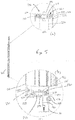
- a domestic greenhouse 100 comprises a framework of elongate aluminium extrusions that define the edges of two rectangular side walls 110, 120 ad two end walls 130,140.
- Each side wall comprises a rectangular framework and each end wall comprises a rectangular framework topped by an equilateral triangular shaped framework.
- the walls support two roof panels 150,160 that meet at a ridge 170.
- An optional decorative trim is provided along the ridge.
- the base part of the framework forming the two side walls and end walls sits on a rectangular footpad, typically constructed as a single concrete slab, a patchwork of small concrete slabs or pavers or a gravel bed.
- This basic shape can be manufactured in a variety of shapes and sizes with lengths and widths varying from, for example, 1.2m to 2.4m.
- Each side and end wall is divided up into small regular spaces by a series of vertical and horizontal aluminium extrusions. Each space is filled with a panel such as a glass sheet.
- the sheets are typically 61 cm (2 feet) wide along the end and side walls and as shown approximately 2 m tall (6 feet).
- One end wall 130 is provided with a doorway opening 180. This is difficult to see in Figure 1 because it is obscured by a pair of closed doors 200,210 However it is easy to see in Figure 2 which is an identical view of the greenhouse but with the doors fully open.
- the doorway is defined by a frame comprising two upright edge pieces 190,191 and a horizontal top piece 192 that connects them together.
- the doorway 190 has no bottom bar, known as a threshold strip, connecting the two uprights as would be required in a conventional prior art greenhouse structure. This is possible due to innovative support arrangements for the door as will now be explained.
- the two doors 200, 210 when closed as shown in Figure 1 meet in the middle of the doorway 190 and cover the doorway opening. When open the two doors allow a person to pass through the doorway opening 190 for access into or out of the greenhouse 100.
- Each of the doors 200, 210 can slide between the open and closed positions.
- the doors are identical, as well as the way they are supported, apart from being handed left or right. Therefore for convenience only one door (the right hand door 210 when viewed from the front) will be described in detail.
- the door 210 comprises an aluminium frame which is infilled with glass panels to match the rest of the building.
- the door 210 is secured to the end wall 130 by a pair of support assemblies so that it can be slid between the open and the closed position.
- the door 210 is supported at the top and the bottom by a pair of support assemblies 220,230.
- Figure 5(a) and (b) shows the assemblies in cross section.
- Each support assembly in this example is identical to the other and comprises a telescopic guide having a base part 221,231 that is secured to the end wall and a sliding part 222,232 that is secured to the door 210.
- the sliding part is displaceable relative to the fixed base part as runs on multiple bearings 223,224.
- the sliding part is actually formed as two sub-parts, each being displaceable relative to the other, to increase the distance over which it can telescope for a given compacted length.
- each guide comprises a web having a substantially flat back plate 225,235, such as a metal strip, having a length in the direction of telescopic movement and a width, the back plate having two side cheeks 224,234 that extend along each long side of the back plate, the base plate and side cheeks having a generally c-shaped cross section.
- the moving part also comprises a substantially flat plate such as a metal strip that is slidably secured to the back plate through the plurality of support bearings 223,233 that engage and are retained by the cheeks of the fixed part.
- the bearings may comprise roller bearings, ball bearings or simple low friction bushes. In this example they comprise ball bearings.
- the base plate is fixed in a horizontal orientation with the moving part hung from the base plate, i.e. the moving part is below the fixed part.
- horizontal we mean that the flat plate lies horizontally and the telescopic guides take up little vertical height. This allows them to be easily hidden in a groove on an underside of an extrusion forming part of the end wall.
- the top support assembly 220 is secured so that the fixed base portion 225 is located directly above the door opening on an underside of the doorway top part 193, so that with the door closed the telescopic guide is in a fully retracted position. This is shown in detail (a) of Figure 3(a) .
- the moving part of the telescopic guide extends away from the fixed part.
- the bottom support assembly 230 is secured so that base portion is located in a downwardly extending groove in a part of the frame of the end panel to the side of the door opening, so that with the door open the telescopic guide is fully retracted. Locating it to the side ensures that the doorway has no threshold at the bottom of the door, which would otherwise form a possible trip hazard.
- the guide is extended.
- the fixed part of the upper telescopic guide is secured directly to the frame using a plurality of bolts as shown in Figure 5(a) . This provides a fixed datum for the door relative to the end wall.
- the fixed part of the lower telescopic guide is secured to an adjustable bracket 240 that forms part of the lower support assembly, and this is in turn secured to the frame by bolts 250.
- the bolts pass though oversize holes allowing the bracket to be adjusted vertically.
- the fixed part of the guide is bolted to this bracket 240 using bolts that allow some adjustment horizontally.
- the moving part of the lower telescopic guide 230 is secured to a further adjustable bracket 260 by bolts 270 that is in turn secured to the door by bolts 280.
- This bracket carries a brush strip that forms a seal with the base of the doorway.
- the second adjustable bracket allows the bottom of the door to be adjusted in and out and up and down (towards and away from the wall as well as vertically).
- the brackets are adjusted so that the door moves smoothly without any binding of the telescopic guides.
- a greenhouse may be provided that has only one sliding door that opens to the left or the right when viewed from the front.
- the door would be sized to completely cover the doorway when closed.
- the greenhouse provided would have no threshold and would also not have any unsightly sideward protruding guiderails for the door as is known in the prior art.
Landscapes
- Engineering & Computer Science (AREA)
- Mechanical Engineering (AREA)
- Life Sciences & Earth Sciences (AREA)
- Environmental Sciences (AREA)
- Civil Engineering (AREA)
- Structural Engineering (AREA)
- Greenhouses (AREA)
Description
- This invention relates to improvements in greenhouses for domestic use.
- A greenhouse, sometimes called a glasshouse, is a building which has walls and a roof that are typically wholly made of a transparent, or opaque, material such as glass or plastic to allow a large amount of sunlight to enter the building and to trap the resulting heat given off by parts of the building or its contents within the building so as to provide a favourable artificially warm climate in which plants can be grown.
- In many parts of the world, such as Northern Europe, a greenhouse is all but essential for use in growing many types of plants and protecting them from the effects of heavy rain, frosts and strong winds. As such, they are a popular feature in the gardens of many homes.
- A common arrangement of greenhouse comprises a framework of metal, typically extruded aluminium, bars, with glass panels infilling the spaces between the bars. The bars are arranged to form bays which contain one or more panels, and by appropriate selection of the number of bays greenhouses of many different shapes, lengths and widths can be made using a limited selection of components. For instance, using panels that are 2 feet (60cm) in width it is possible to provide 4 bays to form a greenhouse 8 foot long or 5 bays to provide a greenhouse 10 foot long.
- Greenhouses may be free standing or lean to structures. A common shape of free standing domestic greenhouse has two parallel side walls and a roof that connects them that has a ridge line and forms an inverted v shape. A decorative trim may be provided along the top of the ridge line. The walls and roof are closed at each end by an end wall, and one end wall has a door or pair of doors. The top of the doors is typically aligned with the base of the roof and is high enough for an average height person to enter without stooping.
- Other shapes are also known, including a lean to greenhouse structure in which a portion of a wall of another building, such as a the side of a house or garage, is used to form one wall of the greenhouse. The rest of the building in effect "leans" against this wall although in practice the wall may not actually carry any structural loading from the greenhouse. In a lean to structure, not all of the walls of the greenhouse will be transparent.
- Hybrid structures are also known, in which part of the greenhouse is transparent and part opaque are also known. For example one end of the structure may be made of wood to provide a secure storage area where valuable tools can be hidden from prying eyes and kept safely out of reach when not in use.
- To gain entry to the building it is common to provide either a single door or a pair of doors in an end of the building.
- It is known to provide sliding doors or hinged doors. A sliding door will be supported along a bottom edge by locating the bottom edge in an upward facing groove provided in a threshold strip that extends all the way from one side of the doorway, across the doorway past the other side of the doorway and on by a distance that is equal to the width of the door. The top of the door is also retained in a similar downward facing groove in a guide track. This arrangement has the disadvantage that stones can become trapped in the threshold strip that can impede opening of the door. The threshold strip can also impede items being rolled through the doorway and could cause a person to trip. Also, the upper guide track may extend beyond the edge of the greenhouse which some people may consider to be unsightly.
- We are aware of
CN201015324 which teaches a greenhouse with a lower threshold and telescopic sliders. AlsoUS5675946A provides an alternative without a lower threshold andDE29911859U1 andJPH11243790A - According to a first aspect the invention achieved with
claim 1, provides a domestic greenhouse (100) of the kind comprising at least one side wall (110, 120), a roof having at least one roof panel, and at least one end wall (130, 140), and at least one door (200, 210) that in a closed position obscures a doorway (180) opening provided in one of the end walls or side walls and in an open position enables a person access through the doorway,
the door (200, 210) comprises a sliding door that is supported by two support assemblies (220, 230), a first support assembly (220) being located at the top of the door and a second support assembly (230) being located at the bottom of the door, each support assembly (220, 230) comprising a telescopic guide having a part secured to the wall of the greenhouse and a part secured to the door(200, 210), characterised in that the part of the second support assembly (230) is fixed to the wall to one side of the doorway so that the doorway opening does not have a lower threshold strip and in that the fixed part of the upper telescopic support assembly (220) is located above the door opening, so that with the door closed the upper telescopic support assembly is in a contracted position and is extended when the door is open, and the fixed part of the lower track is located to one side of the door so that with the door closed it is extended and when open it is contracted. - Where a prior art door of a greenhouse simply slots into and slides within a pair of grooves the door of the present invention is supported by telescopic guides that connect the door to the end of the greenhouse. The use of guides provides a more secure and potentially smoother running sliding door and enables the doorway to be constructed without a threshold strip.
- This arrangement has the benefit that when the door is fully open or closed one of the telescopic supports is retracted, where it has greater strength that it does when fully extended. If both were provided to the side of the door they would both be extended when the door is closed which could make it easier to cause accidental damage to the guides.
- When closed one of the telescopic guides may be fully retracted and when open the other may be fully retracted. This ensures that the door is securely held in place, as the telescopic guides can generally cope with the highest loads when fully retracted.
- Another benefit of locating the fixed part of the first guide assembly above the doorway is that there is no need for unsightly tracks extending out beyond the side of the greenhouse as typically is need with a prior art sliding door on a relatively small greenhouse.
- The telescopic guide may comprise an elongate moving part and an elongate fixed part. The moving part and fixed part are connected so that the moving part in use can move, by sliding, in a direction along its long axis relative to an elongate fixed part, thereby varying the overall length of the telescopic guide.
- Each of the telescopic guides may comprise a fixed part having a substantially flat back plate having a length in the direction of telescopic movement and a width, the back plate having two side cheeks that extends along each long side of the back plate, the base plate and side cheeks having a generally c-shaped cross section, the moving part also comprising a substantially flat plate that is slidably secured to the back plate using a plurality of support bearings that engage and are retained by the cheeks of the fixed part.
- The bearings may comprise roller bearings, ball bearings or simple low friction bushes.
- In a modification, the moving part of the guide assembly may comprise two moving sub-parts, one telescopically sliding relative to the fixed part, and the other telescopically sliding relative to the first moving sub-part. In this case, the first sliding subpart may be similar to the fixed, having its own side cheeks that engage and retain bearings of the second sliding sub part. This arrangement allows the overall length of the assembly to be shorter for a given range of telescopic movement compared with one with a single moving part.
The moving part of each telescopic guide may be secured to the door and the fixed part secured to the end of the greenhouse so that the flat back plate lies in a horizontal plane. In this position, the guide will be shallower than it is wide, and so it will provide good resistance to attempts to pull the door horizontally away from the end of the greenhouse compared with the guide back plate being a vertical plane. - In a most preferred arrangement the telescopic guides may be located in such a way that the moving parts "hang" down from the fixed part. This way, the back plate will be facing upwards with the slide supported by the cheeks through the bearings. This will carry the weight of the door, and any expected load applied to the door, for example as a person pushes down on the door when opening or closing or when exposed to the wind.
- Each guide may be secured by one or more bolts or screws to the door and the wall of the greenhouse. These may pass through openings in the fixed part and moving part of the telescopic guide as appropriate.
- Each telescopic guide may be self-closing by which we mean that at the end of travel when retracting the slide actively moves the door to the final rest position.
- To accommodate variations in the size of the door and doorway during manufacture of assembly, one of the support assemblies may include an adjustable bracket, the telescopic guide being secured to the door or to the end of the greenhouse using the adjustable bracket.
- In one arrangement the first support assembly is secured using a non-adjustable bracket and the second support assembly is secured through at least one adjustable bracket.
- One adjustable bracket may secure the fixed part of the telescopic guide to the wall, and another may secure the moving part of the door. The adjustable brackets may be configured during assembly to permit the location of the fixed part relative to the end of the greenhouse to be adjusted vertically and also horizontally, and also the door relative to the wall. This allows the door to be adjusted to ensure that the telescopic guides do not bind when opening or closing.
- The base of the door may be provided with a seal that extends from one edge of the door to the other so that the seal contacts the ground where a threshold strip would otherwise be provided. This may comprise a brush strip or similar weather seal.
- The second support assembly may be located a distance above the bottom of the greenhouse to protect it from debris, and protected by an overhanging cover part which forms a part of the end of the greenhouse.
- The support assembly may include an extruded frame part that forms a channel within which the fixed part is located, including any bracket where provided.
- The greenhouse may include two doors, each one having the features described above and supported by respective first and second support assemblies. They may each be approximately half the width of the doorway and when closed meet in the middle of the doorway.
- The walls of the greenhouse may comprise a plurality of bars that define spaces within which clear or opaque panels are located. The panels may comprise glass panels. The bars may comprise aluminium extrusions. The bars may comprise vertical bars and horizontal bars that form rectangular spaces within which the panels are located.
- The door or doors may be provided in an end or a side wall of the greenhouse. Where a single door is provided it may slide to the left or to the right on opening, as viewed from outside the greenhouse facing the door.
- The door may be located on the outside of the doorway so that when slide open it lies outside of the greenhouse overlapping the wall.
- The greenhouse may include two sliding doors that abut at a centre of the doorway. Each door may be arranged as described herein, supported by telescopic slides at the top and bottom of each door.
- The roof panel may comprise two half panels that meet at an apex defining a ridge that is located generally midway between the two side walls to form a roof that has an inverted V-shape.
- There will now be described, by way of example only,
-
Figure 1 is a perspective view of an embodiment of a greenhouse in accordance with the present invention with the double doors in a closed position; -
Figure 2 is a perspective view of an embodiment of a greenhouse in accordance with the present invention with the double doors in a fully open position; -
Figure 3(a) is a detail view of a top part of the doorway and end wall of the greenhouse ofFigure 1 and(b) is a detail view of a bottom part of the doorway and end wall, each detail showing the location of the fixed part of the doorway support assemblies and with the doors closed; -
Figure 4(a) is a detail view of the top part of the doorway and end wall of the greenhouse ofFigure 1 and(b) is a detail view of the bottom part of the doorway and end wall, each detail showing the location of the fixed part of the doorway support assemblies and with the doors open; and -
Figure 5 (a) is a detail view of the first support assembly and the connection to the door and end wall as viewed in cross section, and (d) is a corresponding detail view of the second, lower, support assembly viewed in cross section that also shows the adjustable support bracket that secures the support assembly to the end wall. - As shown in
Figure 1 , adomestic greenhouse 100 comprises a framework of elongate aluminium extrusions that define the edges of tworectangular side walls 110, 120 ad two end walls 130,140. Each side wall comprises a rectangular framework and each end wall comprises a rectangular framework topped by an equilateral triangular shaped framework. The walls support two roof panels 150,160 that meet at a ridge 170. An optional decorative trim is provided along the ridge. - The base part of the framework forming the two side walls and end walls sits on a rectangular footpad, typically constructed as a single concrete slab, a patchwork of small concrete slabs or pavers or a gravel bed. This basic shape can be manufactured in a variety of shapes and sizes with lengths and widths varying from, for example, 1.2m to 2.4m.
- Each side and end wall is divided up into small regular spaces by a series of vertical and horizontal aluminium extrusions. Each space is filled with a panel such as a glass sheet. The sheets are typically 61 cm (2 feet) wide along the end and side walls and as shown approximately 2 m tall (6 feet).
- One
end wall 130 is provided with adoorway opening 180. This is difficult to see inFigure 1 because it is obscured by a pair of closed doors 200,210 However it is easy to see inFigure 2 which is an identical view of the greenhouse but with the doors fully open. The doorway is defined by a frame comprising two upright edge pieces 190,191 and a horizontaltop piece 192 that connects them together. - As can be seen in
Figure 2 , the doorway 190 has no bottom bar, known as a threshold strip, connecting the two uprights as would be required in a conventional prior art greenhouse structure. This is possible due to innovative support arrangements for the door as will now be explained. - The two
doors Figure 1 meet in the middle of the doorway 190 and cover the doorway opening. When open the two doors allow a person to pass through the doorway opening 190 for access into or out of thegreenhouse 100. - Each of the
doors right hand door 210 when viewed from the front) will be described in detail. - The
door 210 comprises an aluminium frame which is infilled with glass panels to match the rest of the building. Thedoor 210 is secured to theend wall 130 by a pair of support assemblies so that it can be slid between the open and the closed position. - The
door 210 is supported at the top and the bottom by a pair of support assemblies 220,230.Figure 5(a) and (b) shows the assemblies in cross section. - Each support assembly in this example is identical to the other and comprises a telescopic guide having a base part 221,231 that is secured to the end wall and a sliding part 222,232 that is secured to the
door 210. The sliding part is displaceable relative to the fixed base part as runs on multiple bearings 223,224. In this example, the sliding part is actually formed as two sub-parts, each being displaceable relative to the other, to increase the distance over which it can telescope for a given compacted length. - The fixed part of each guide comprises a web having a substantially flat back plate 225,235, such as a metal strip, having a length in the direction of telescopic movement and a width, the back plate having two side cheeks 224,234 that extend along each long side of the back plate, the base plate and side cheeks having a generally c-shaped cross section. The moving part also comprises a substantially flat plate such as a metal strip that is slidably secured to the back plate through the plurality of support bearings 223,233 that engage and are retained by the cheeks of the fixed part.
- The bearings may comprise roller bearings, ball bearings or simple low friction bushes. In this example they comprise ball bearings.
- In each case, the base plate is fixed in a horizontal orientation with the moving part hung from the base plate, i.e. the moving part is below the fixed part. By horizontal we mean that the flat plate lies horizontally and the telescopic guides take up little vertical height. This allows them to be easily hidden in a groove on an underside of an extrusion forming part of the end wall.
- The
top support assembly 220 is secured so that the fixedbase portion 225 is located directly above the door opening on an underside of the doorwaytop part 193, so that with the door closed the telescopic guide is in a fully retracted position. This is shown in detail (a) ofFigure 3(a) . When the door is opened as shown in detail (a) ofFigure 4(a) the moving part of the telescopic guide extends away from the fixed part. - The
bottom support assembly 230 is secured so that base portion is located in a downwardly extending groove in a part of the frame of the end panel to the side of the door opening, so that with the door open the telescopic guide is fully retracted. Locating it to the side ensures that the doorway has no threshold at the bottom of the door, which would otherwise form a possible trip hazard. When the door is closed, as shown inFigure 4(b) the guide is extended. - The fixed part of the upper telescopic guide is secured directly to the frame using a plurality of bolts as shown in
Figure 5(a) . This provides a fixed datum for the door relative to the end wall. - The fixed part of the lower telescopic guide is secured to an
adjustable bracket 240 that forms part of the lower support assembly, and this is in turn secured to the frame by bolts 250. The bolts pass though oversize holes allowing the bracket to be adjusted vertically. The fixed part of the guide is bolted to thisbracket 240 using bolts that allow some adjustment horizontally. - The moving part of the lower
telescopic guide 230 is secured to a furtheradjustable bracket 260 bybolts 270 that is in turn secured to the door by bolts 280. This bracket carries a brush strip that forms a seal with the base of the doorway. The second adjustable bracket allows the bottom of the door to be adjusted in and out and up and down (towards and away from the wall as well as vertically). - The brackets are adjusted so that the door moves smoothly without any binding of the telescopic guides.
- The reader will appreciate that several modifications are possible. In particular, although the example shown has double doors at one end, a greenhouse may be provided that has only one sliding door that opens to the left or the right when viewed from the front. In this case, the door would be sized to completely cover the doorway when closed. As with the double door arrangement, the greenhouse provided would have no threshold and would also not have any unsightly sideward protruding guiderails for the door as is known in the prior art.
Claims (9)
- A domestic greenhouse (100) of the kind comprising at least one side wall (110, 120), a roof having at least one roof panel, and at least one end wall (130, 140), and at least one door (200, 210) that in a closed position obscures a doorway (180) opening provided in one of the end walls or side walls and in an open position enables a person access through the doorway,
the door (200, 210) comprises a sliding door that is supported by two support assemblies (220, 230), a first support assembly (220) being located at the top of the door and a second support assembly (230) being located at the bottom of the door, each support assembly (220, 230) comprising a telescopic guide having a part secured to the wall of the greenhouse and a part secured to the door(200, 210), characterised in that the part of the second support assembly (230) is fixed to the wall to one side of the doorway so that the doorway opening does not have a lower threshold strip and in that the fixed part of the upper telescopic support assembly (220) is located above the door opening, so that with the door closed the upper telescopic support assembly is in a contracted position and is extended when the door is open, and the fixed part of the lower track is located to one side of the door so that with the door closed it is extended and when open it is contracted. - A domestic greenhouse according to claim 1 arranged so that when closed one of the telescopic guides is fully retracted and when open the other is fully retracted.
- A domestic greenhouse according to any preceding claim in which each of the telescopic guides comprises a fixed part having a substantially flat back plate having a length in the direction of telescopic movement and a width, the back plate having two side cheeks that extends along each long side of the back plate, the base plate and side cheeks having a generally c-shaped cross section, the moving part also comprising a substantially flat plate that is displaceably secured to the back plate using a plurality of support bearings that engage and are retained by the cheeks of the fixed part.
- A domestic greenhouse according to claim 3 in which the moving part of each telescopic guide is secured to the door and the fixed part secured to the end of the greenhouse so that the flat back plate lies in a horizontal plane such that the moving parts "hang" down from the fixed part.
- A domestic greenhouse according to any preceding claim in which one of the support assemblies (220, 230) includes an adjustable bracket, the telescopic guide being secured to the door or to the end of the greenhouse using the adjustable bracket.
- A domestic greenhouse according to claim 5 in which the first support assembly (220) is secured using a non-adjustable bracket and the second support assembly (230) is secured through at least one adjustable bracket.
- A domestic greenhouse according to claim 5 or claim 6 in which one adjustable bracket is secured the fixed part of the telescopic guide to the wall, and another is secures the moving part of the door.
- A domestic greenhouse according to any preceding claim in which the base of the door (200, 210) is provided with a seal that extends from one edge of the door to the other so that the seal contacts the ground where a threshold strip would otherwise be provided. This may comprise a brush strip or similar weather seal.
- A domestic greenhouse according to any preceding claim which comprises a free standing type greenhouse or a lean-to type greenhouse.
Applications Claiming Priority (1)
| Application Number | Priority Date | Filing Date | Title |
|---|---|---|---|
| GBGB1415430.6A GB201415430D0 (en) | 2014-09-01 | 2014-09-01 | Improvements in domestic greenhouses |
Publications (2)
| Publication Number | Publication Date |
|---|---|
| EP2989886A1 EP2989886A1 (en) | 2016-03-02 |
| EP2989886B1 true EP2989886B1 (en) | 2019-11-06 |
Family
ID=51752424
Family Applications (1)
| Application Number | Title | Priority Date | Filing Date |
|---|---|---|---|
| EP15183382.9A Active EP2989886B1 (en) | 2014-09-01 | 2015-09-01 | Improvements in domestic greenhouses |
Country Status (2)
| Country | Link |
|---|---|
| EP (1) | EP2989886B1 (en) |
| GB (2) | GB201415430D0 (en) |
Families Citing this family (1)
| Publication number | Priority date | Publication date | Assignee | Title |
|---|---|---|---|---|
| JP7108261B2 (en) * | 2018-07-10 | 2022-07-28 | 東都興業株式会社 | Stopper mechanism for self-closing sliding doors for greenhouses |
Citations (1)
| Publication number | Priority date | Publication date | Assignee | Title |
|---|---|---|---|---|
| JPH11243790A (en) * | 1998-03-06 | 1999-09-14 | Toto Kogyo Kk | Lower rail-traveling type sliding door device for plastic film hothouse |
Family Cites Families (9)
| Publication number | Priority date | Publication date | Assignee | Title |
|---|---|---|---|---|
| DE4329807A1 (en) * | 1993-09-03 | 1995-03-09 | Joerg Dipl Ing Drewes | Glazed annexe for a building |
| JP3174901B2 (en) * | 1995-03-30 | 2001-06-11 | 東都興業株式会社 | Hanging door roller for sliding doors and its mounting method |
| US5675946A (en) * | 1996-06-07 | 1997-10-14 | Teknion Furniture Systems | Privacy screen for office panelling systems |
| DE19912143B4 (en) * | 1999-03-18 | 2006-06-14 | Hans Einhell Ag | Component set for the construction of a greenhouse |
| DE29915279U1 (en) * | 1999-09-01 | 2001-02-08 | Diener, Horst, 89079 Ulm | sliding door |
| GB2418221B (en) * | 2004-09-17 | 2009-06-24 | Westinghouse Brakes | Platform screen door system |
| CN201015324Y (en) * | 2007-03-19 | 2008-02-06 | 吴忠成 | Improved structure of novel greenhouse |
| JP5676243B2 (en) * | 2010-12-28 | 2015-02-25 | 佐藤産業株式会社 | Door car, connecting structure of door car and suspension door |
| FR2994987B1 (en) * | 2012-08-30 | 2014-08-22 | Mobil Home Rideau | ASSEMBLY COMPRISING A MAIN CONSTRUCTION AND A SECONDARY CONSTRUCTION |
-
2014
- 2014-09-01 GB GBGB1415430.6A patent/GB201415430D0/en not_active Ceased
-
2015
- 2015-09-01 EP EP15183382.9A patent/EP2989886B1/en active Active
- 2015-09-01 GB GB1515497.4A patent/GB2530904A/en not_active Withdrawn
Patent Citations (1)
| Publication number | Priority date | Publication date | Assignee | Title |
|---|---|---|---|---|
| JPH11243790A (en) * | 1998-03-06 | 1999-09-14 | Toto Kogyo Kk | Lower rail-traveling type sliding door device for plastic film hothouse |
Also Published As
| Publication number | Publication date |
|---|---|
| GB2530904A (en) | 2016-04-06 |
| GB201515497D0 (en) | 2015-10-14 |
| GB201415430D0 (en) | 2014-10-15 |
| EP2989886A1 (en) | 2016-03-02 |
Similar Documents
| Publication | Publication Date | Title |
|---|---|---|
| US6604327B1 (en) | Retractable spa enclosure | |
| AU2015363282B2 (en) | Pergola cover | |
| US9915062B2 (en) | Structure having convertible roof and walls | |
| US8347935B2 (en) | Rigid retractable patio or window awning and operating mechanisms therefor | |
| US4571898A (en) | Sales boutique, especially a newspaper kiosk | |
| AU2014360947B2 (en) | Venetian blind | |
| EP2460969B1 (en) | Double-sash roof window with side barriers | |
| EP2989886B1 (en) | Improvements in domestic greenhouses | |
| DE4329807A1 (en) | Glazed annexe for a building | |
| US9435135B1 (en) | Adjustable fence systems | |
| US4035965A (en) | Collapsible combination fence and garage structure | |
| US3341180A (en) | Combined wall and awning structure | |
| US4608788A (en) | Adjustable overhang panel for building eave | |
| EP3124716B1 (en) | Solar protection system with a movable pergola | |
| DE4229661A1 (en) | Movable window units for sloping roof of winter garden - slide over fixed window units and are moved by toothed belts passing over sprockets | |
| JP6019476B2 (en) | Building greening structure | |
| CN1436912A (en) | Multifunctional lifted balcony guard fence | |
| KR101851466B1 (en) | Green house having skylight window for open and closed | |
| CN201133107Y (en) | Sliding cloth type triangular top tent | |
| US20160362930A1 (en) | Window blind protector | |
| TWM555397U (en) | Foldable guardrail having extendable structure | |
| RU2786950C1 (en) | Fence-slider section | |
| CN201137321Y (en) | Four-side sliding cloth type tent | |
| CN201133110Y (en) | Sliding cloth type tent | |
| KR100848684B1 (en) | A stand for bower and agricultural products sale |
Legal Events
| Date | Code | Title | Description |
|---|---|---|---|
| PUAI | Public reference made under article 153(3) epc to a published international application that has entered the european phase |
Free format text: ORIGINAL CODE: 0009012 |
|
| AK | Designated contracting states |
Kind code of ref document: A1 Designated state(s): AL AT BE BG CH CY CZ DE DK EE ES FI FR GB GR HR HU IE IS IT LI LT LU LV MC MK MT NL NO PL PT RO RS SE SI SK SM TR |
|
| AX | Request for extension of the european patent |
Extension state: BA ME |
|
| 17P | Request for examination filed |
Effective date: 20160902 |
|
| RBV | Designated contracting states (corrected) |
Designated state(s): AL AT BE BG CH CY CZ DE DK EE ES FI FR GB GR HR HU IE IS IT LI LT LU LV MC MK MT NL NO PL PT RO RS SE SI SK SM TR |
|
| STAA | Information on the status of an ep patent application or granted ep patent |
Free format text: STATUS: EXAMINATION IS IN PROGRESS |
|
| 17Q | First examination report despatched |
Effective date: 20170721 |
|
| GRAP | Despatch of communication of intention to grant a patent |
Free format text: ORIGINAL CODE: EPIDOSNIGR1 |
|
| STAA | Information on the status of an ep patent application or granted ep patent |
Free format text: STATUS: GRANT OF PATENT IS INTENDED |
|
| RIC1 | Information provided on ipc code assigned before grant |
Ipc: E05D 15/06 20060101ALI20190326BHEP Ipc: A01G 9/14 20060101AFI20190326BHEP Ipc: A01G 9/24 20060101ALN20190326BHEP |
|
| INTG | Intention to grant announced |
Effective date: 20190412 |
|
| RIC1 | Information provided on ipc code assigned before grant |
Ipc: A01G 9/24 20060101ALN20190401BHEP Ipc: A01G 9/14 20060101AFI20190401BHEP Ipc: E05D 15/06 20060101ALI20190401BHEP |
|
| RIN1 | Information on inventor provided before grant (corrected) |
Inventor name: SNAPE, JAN Inventor name: BOULTON, BRETT |
|
| GRAS | Grant fee paid |
Free format text: ORIGINAL CODE: EPIDOSNIGR3 |
|
| RAP1 | Party data changed (applicant data changed or rights of an application transferred) |
Owner name: JULIANA GROUP LIMITED |
|
| GRAA | (expected) grant |
Free format text: ORIGINAL CODE: 0009210 |
|
| STAA | Information on the status of an ep patent application or granted ep patent |
Free format text: STATUS: THE PATENT HAS BEEN GRANTED |
|
| AK | Designated contracting states |
Kind code of ref document: B1 Designated state(s): AL AT BE BG CH CY CZ DE DK EE ES FI FR GB GR HR HU IE IS IT LI LT LU LV MC MK MT NL NO PL PT RO RS SE SI SK SM TR |
|
| REG | Reference to a national code |
Ref country code: GB Ref legal event code: FG4D |
|
| REG | Reference to a national code |
Ref country code: CH Ref legal event code: EP Ref country code: AT Ref legal event code: REF Ref document number: 1197534 Country of ref document: AT Kind code of ref document: T Effective date: 20191115 |
|
| REG | Reference to a national code |
Ref country code: DE Ref legal event code: R096 Ref document number: 602015040991 Country of ref document: DE |
|
| REG | Reference to a national code |
Ref country code: IE Ref legal event code: FG4D |
|
| REG | Reference to a national code |
Ref country code: NL Ref legal event code: MP Effective date: 20191106 |
|
| REG | Reference to a national code |
Ref country code: LT Ref legal event code: MG4D |
|
| PG25 | Lapsed in a contracting state [announced via postgrant information from national office to epo] |
Ref country code: LV Free format text: LAPSE BECAUSE OF FAILURE TO SUBMIT A TRANSLATION OF THE DESCRIPTION OR TO PAY THE FEE WITHIN THE PRESCRIBED TIME-LIMIT Effective date: 20191106 Ref country code: SE Free format text: LAPSE BECAUSE OF FAILURE TO SUBMIT A TRANSLATION OF THE DESCRIPTION OR TO PAY THE FEE WITHIN THE PRESCRIBED TIME-LIMIT Effective date: 20191106 Ref country code: NL Free format text: LAPSE BECAUSE OF FAILURE TO SUBMIT A TRANSLATION OF THE DESCRIPTION OR TO PAY THE FEE WITHIN THE PRESCRIBED TIME-LIMIT Effective date: 20191106 Ref country code: FI Free format text: LAPSE BECAUSE OF FAILURE TO SUBMIT A TRANSLATION OF THE DESCRIPTION OR TO PAY THE FEE WITHIN THE PRESCRIBED TIME-LIMIT Effective date: 20191106 Ref country code: BG Free format text: LAPSE BECAUSE OF FAILURE TO SUBMIT A TRANSLATION OF THE DESCRIPTION OR TO PAY THE FEE WITHIN THE PRESCRIBED TIME-LIMIT Effective date: 20200206 Ref country code: PT Free format text: LAPSE BECAUSE OF FAILURE TO SUBMIT A TRANSLATION OF THE DESCRIPTION OR TO PAY THE FEE WITHIN THE PRESCRIBED TIME-LIMIT Effective date: 20200306 Ref country code: LT Free format text: LAPSE BECAUSE OF FAILURE TO SUBMIT A TRANSLATION OF THE DESCRIPTION OR TO PAY THE FEE WITHIN THE PRESCRIBED TIME-LIMIT Effective date: 20191106 Ref country code: NO Free format text: LAPSE BECAUSE OF FAILURE TO SUBMIT A TRANSLATION OF THE DESCRIPTION OR TO PAY THE FEE WITHIN THE PRESCRIBED TIME-LIMIT Effective date: 20200206 Ref country code: PL Free format text: LAPSE BECAUSE OF FAILURE TO SUBMIT A TRANSLATION OF THE DESCRIPTION OR TO PAY THE FEE WITHIN THE PRESCRIBED TIME-LIMIT Effective date: 20191106 Ref country code: GR Free format text: LAPSE BECAUSE OF FAILURE TO SUBMIT A TRANSLATION OF THE DESCRIPTION OR TO PAY THE FEE WITHIN THE PRESCRIBED TIME-LIMIT Effective date: 20200207 |
|
| PG25 | Lapsed in a contracting state [announced via postgrant information from national office to epo] |
Ref country code: HR Free format text: LAPSE BECAUSE OF FAILURE TO SUBMIT A TRANSLATION OF THE DESCRIPTION OR TO PAY THE FEE WITHIN THE PRESCRIBED TIME-LIMIT Effective date: 20191106 Ref country code: RS Free format text: LAPSE BECAUSE OF FAILURE TO SUBMIT A TRANSLATION OF THE DESCRIPTION OR TO PAY THE FEE WITHIN THE PRESCRIBED TIME-LIMIT Effective date: 20191106 Ref country code: IS Free format text: LAPSE BECAUSE OF FAILURE TO SUBMIT A TRANSLATION OF THE DESCRIPTION OR TO PAY THE FEE WITHIN THE PRESCRIBED TIME-LIMIT Effective date: 20200306 |
|
| PG25 | Lapsed in a contracting state [announced via postgrant information from national office to epo] |
Ref country code: AL Free format text: LAPSE BECAUSE OF FAILURE TO SUBMIT A TRANSLATION OF THE DESCRIPTION OR TO PAY THE FEE WITHIN THE PRESCRIBED TIME-LIMIT Effective date: 20191106 |
|
| PG25 | Lapsed in a contracting state [announced via postgrant information from national office to epo] |
Ref country code: RO Free format text: LAPSE BECAUSE OF FAILURE TO SUBMIT A TRANSLATION OF THE DESCRIPTION OR TO PAY THE FEE WITHIN THE PRESCRIBED TIME-LIMIT Effective date: 20191106 Ref country code: ES Free format text: LAPSE BECAUSE OF FAILURE TO SUBMIT A TRANSLATION OF THE DESCRIPTION OR TO PAY THE FEE WITHIN THE PRESCRIBED TIME-LIMIT Effective date: 20191106 Ref country code: CZ Free format text: LAPSE BECAUSE OF FAILURE TO SUBMIT A TRANSLATION OF THE DESCRIPTION OR TO PAY THE FEE WITHIN THE PRESCRIBED TIME-LIMIT Effective date: 20191106 Ref country code: DK Free format text: LAPSE BECAUSE OF FAILURE TO SUBMIT A TRANSLATION OF THE DESCRIPTION OR TO PAY THE FEE WITHIN THE PRESCRIBED TIME-LIMIT Effective date: 20191106 Ref country code: EE Free format text: LAPSE BECAUSE OF FAILURE TO SUBMIT A TRANSLATION OF THE DESCRIPTION OR TO PAY THE FEE WITHIN THE PRESCRIBED TIME-LIMIT Effective date: 20191106 |
|
| REG | Reference to a national code |
Ref country code: DE Ref legal event code: R097 Ref document number: 602015040991 Country of ref document: DE |
|
| REG | Reference to a national code |
Ref country code: AT Ref legal event code: MK05 Ref document number: 1197534 Country of ref document: AT Kind code of ref document: T Effective date: 20191106 |
|
| PG25 | Lapsed in a contracting state [announced via postgrant information from national office to epo] |
Ref country code: SK Free format text: LAPSE BECAUSE OF FAILURE TO SUBMIT A TRANSLATION OF THE DESCRIPTION OR TO PAY THE FEE WITHIN THE PRESCRIBED TIME-LIMIT Effective date: 20191106 Ref country code: SM Free format text: LAPSE BECAUSE OF FAILURE TO SUBMIT A TRANSLATION OF THE DESCRIPTION OR TO PAY THE FEE WITHIN THE PRESCRIBED TIME-LIMIT Effective date: 20191106 |
|
| PLBE | No opposition filed within time limit |
Free format text: ORIGINAL CODE: 0009261 |
|
| STAA | Information on the status of an ep patent application or granted ep patent |
Free format text: STATUS: NO OPPOSITION FILED WITHIN TIME LIMIT |
|
| 26N | No opposition filed |
Effective date: 20200807 |
|
| PG25 | Lapsed in a contracting state [announced via postgrant information from national office to epo] |
Ref country code: SI Free format text: LAPSE BECAUSE OF FAILURE TO SUBMIT A TRANSLATION OF THE DESCRIPTION OR TO PAY THE FEE WITHIN THE PRESCRIBED TIME-LIMIT Effective date: 20191106 Ref country code: AT Free format text: LAPSE BECAUSE OF FAILURE TO SUBMIT A TRANSLATION OF THE DESCRIPTION OR TO PAY THE FEE WITHIN THE PRESCRIBED TIME-LIMIT Effective date: 20191106 |
|
| PG25 | Lapsed in a contracting state [announced via postgrant information from national office to epo] |
Ref country code: IT Free format text: LAPSE BECAUSE OF FAILURE TO SUBMIT A TRANSLATION OF THE DESCRIPTION OR TO PAY THE FEE WITHIN THE PRESCRIBED TIME-LIMIT Effective date: 20191106 |
|
| PG25 | Lapsed in a contracting state [announced via postgrant information from national office to epo] |
Ref country code: MC Free format text: LAPSE BECAUSE OF FAILURE TO SUBMIT A TRANSLATION OF THE DESCRIPTION OR TO PAY THE FEE WITHIN THE PRESCRIBED TIME-LIMIT Effective date: 20191106 |
|
| REG | Reference to a national code |
Ref country code: CH Ref legal event code: PL |
|
| REG | Reference to a national code |
Ref country code: BE Ref legal event code: MM Effective date: 20200930 |
|
| PG25 | Lapsed in a contracting state [announced via postgrant information from national office to epo] |
Ref country code: LU Free format text: LAPSE BECAUSE OF NON-PAYMENT OF DUE FEES Effective date: 20200901 |
|
| PG25 | Lapsed in a contracting state [announced via postgrant information from national office to epo] |
Ref country code: CH Free format text: LAPSE BECAUSE OF NON-PAYMENT OF DUE FEES Effective date: 20200930 Ref country code: BE Free format text: LAPSE BECAUSE OF NON-PAYMENT OF DUE FEES Effective date: 20200930 Ref country code: LI Free format text: LAPSE BECAUSE OF NON-PAYMENT OF DUE FEES Effective date: 20200930 |
|
| PG25 | Lapsed in a contracting state [announced via postgrant information from national office to epo] |
Ref country code: TR Free format text: LAPSE BECAUSE OF FAILURE TO SUBMIT A TRANSLATION OF THE DESCRIPTION OR TO PAY THE FEE WITHIN THE PRESCRIBED TIME-LIMIT Effective date: 20191106 Ref country code: MT Free format text: LAPSE BECAUSE OF FAILURE TO SUBMIT A TRANSLATION OF THE DESCRIPTION OR TO PAY THE FEE WITHIN THE PRESCRIBED TIME-LIMIT Effective date: 20191106 Ref country code: CY Free format text: LAPSE BECAUSE OF FAILURE TO SUBMIT A TRANSLATION OF THE DESCRIPTION OR TO PAY THE FEE WITHIN THE PRESCRIBED TIME-LIMIT Effective date: 20191106 |
|
| PG25 | Lapsed in a contracting state [announced via postgrant information from national office to epo] |
Ref country code: MK Free format text: LAPSE BECAUSE OF FAILURE TO SUBMIT A TRANSLATION OF THE DESCRIPTION OR TO PAY THE FEE WITHIN THE PRESCRIBED TIME-LIMIT Effective date: 20191106 |
|
| PGFP | Annual fee paid to national office [announced via postgrant information from national office to epo] |
Ref country code: IE Payment date: 20230926 Year of fee payment: 9 |
|
| PGFP | Annual fee paid to national office [announced via postgrant information from national office to epo] |
Ref country code: FR Payment date: 20230912 Year of fee payment: 9 Ref country code: DE Payment date: 20230907 Year of fee payment: 9 |
|
| PGFP | Annual fee paid to national office [announced via postgrant information from national office to epo] |
Ref country code: GB Payment date: 20240820 Year of fee payment: 10 |