EP3124716B1 - Solar protection system with a movable pergola - Google Patents
Solar protection system with a movable pergola Download PDFInfo
- Publication number
- EP3124716B1 EP3124716B1 EP16168053.3A EP16168053A EP3124716B1 EP 3124716 B1 EP3124716 B1 EP 3124716B1 EP 16168053 A EP16168053 A EP 16168053A EP 3124716 B1 EP3124716 B1 EP 3124716B1
- Authority
- EP
- European Patent Office
- Prior art keywords
- section
- slats
- pergola
- travel means
- moveable
- Prior art date
- Legal status (The legal status is an assumption and is not a legal conclusion. Google has not performed a legal analysis and makes no representation as to the accuracy of the status listed.)
- Active
Links
Images


Classifications
-
- E—FIXED CONSTRUCTIONS
- E04—BUILDING
- E04F—FINISHING WORK ON BUILDINGS, e.g. STAIRS, FLOORS
- E04F10/00—Sunshades, e.g. Florentine blinds or jalousies; Outside screens; Awnings or baldachins
- E04F10/08—Sunshades, e.g. Florentine blinds or jalousies; Outside screens; Awnings or baldachins of a plurality of similar rigid parts, e.g. slabs, lamellae
- E04F10/10—Sunshades, e.g. Florentine blinds or jalousies; Outside screens; Awnings or baldachins of a plurality of similar rigid parts, e.g. slabs, lamellae collapsible or extensible; metallic Florentine blinds; awnings with movable parts such as louvres
Definitions
- This invention relates to a mobile solar protection system and, in particular, a moveable pergola comprising a first vertical section and a second section coupled to the first vertical section at an angle of at least 90o.
- Solar protection is currently very important, since the ultraviolet rays in sunlight may cause skin burns and even cancer in the long term.
- solar protection systems for doors, windows or terraces.
- systems such as awnings or blinds with or without mobile slats.
- Pergolas are not built on buildings, since in these cases awnings are used for solar protection. However, the problem with awnings is that in principle they only protect from the sun from above but not from the sides.
- At least one pergola comprising travel means for the movement of part of the system or of the entire pergola in a specific direction changing thus the area of shade.
- the system may comprise more than one pergola in order to offer solar protection according to the needs, at the same time maintaining maximum flexibility.
- the pergola further comprises two sections that protect from the sun via a plurality of slats that are fixed to each section.
- One section is vertical, whereas the other section is horizontal or inclined.
- These pergolas can be assembled directly on buildings or they can be assembled with an additional support system that allows movement of the horizontal or inclined section.
- This invention refers to a moveable solar protection system that allows easily changing the area of shade provided by the system according to the movement of the sun.
- the system comprises travel means on a first and/or second end in order to perform a lateral travel.
- the solar protection system according to the invention comprises at least one mobile pergola.
- it can comprise more than one pergola in order to offer more solar protection according to the user's needs, for example two, three, four, five or more pergolas.
- the area of shade may thus be extended in a flexible manner.
- These pergolas may have the same dimensions or they can be gradually increased in size in order to allow an overlap between the pergolas so that they can all be stored in one single place: That is, they are moved to a common place one above the other when they are not required.
- the pergola comprises a first vertical section and a second section that is coupled to the first section at an angle of at least 90o with respect to the first vertical section. Therefore, the second section may be horizontal in one aspect or inclined in other aspects of this invention.
- the angle with respect to the first vertical section may vary between 90o and 135o.
- the second section is horizontal (i.e. parallel to the floor) the first and second sections forming an angle of 90o, since this allows for an easier assembly.
- Figure 1 shows in a non-limiting manner a solar protection system 100 according to the invention with a first vertical section 110 and a second section 120 that is coupled to the first section at a 90o angle.
- Each section 110, 120 is formed by a frame that has a first end 112, 122 comprising travel means 113, 123, that is, the moving end, and a second end 114, 124 that makes the connection between the two sections 110, 120, that is, the connecting end.
- Each section 110, 120 further comprises a plurality of slats 111, 121 that are separated from one another and which provide the solar protection, whereas they still allow the passage of sufficient light so that the protected area is not entirely dark.
- the frame comprises at least two lateral beams that are parallel to one another and on which the plurality of slats 111, 121 are mounted.
- the slats are thus mounted parallel to the floor as in any kind of blind.
- the frame may additionally comprise a beam that connects the two lateral beams on one end, preferably on the connecting end 114, 124 to facilitate the coupling of the two sections 110, 120 and to provide more stability.
- the frame comprises an additional beam on each end, that is, it is formed of a total of four beams forming a rectangle, which provides maximum stability and allows a high degree of flexibility for the connection between the two sections 110, 120 and the assembly of the travel means 113, 123.
- the two connecting ends 114, 124 have mounting means (not shown) in order to couple the first vertical section 110 to the second section 120.
- These mounting means may comprise for example screws with nuts, threaded screws or nails and the corresponding openings for a strong or secure fastening.
- the preferred manner of coupling the two sections is via threaded screws.
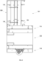
- Figure 2 shows as an example one alternative of a coupling between the first and second sections 110, 120.
- a cross-section is shown illustrating the moving end 112 of the first section 110 and the connecting ends 114, 124 of the first and second sections 110, 120.
- the two connecting ends 114, 124 are fixed via screws 130 that provide the necessary fastening and stability so that the two sections 110, 120 seem like a single unit.
- the number of screws 130 may vary depending on the size of the sections 110, 120.
- the system 100 comprises one single beam that connects the two sections 110, 120 and that is shared by the two connecting ends 114, 124. That is, this shared beam may belong either to the first vertical section 110 or to the second section 120. Therefore, in one aspect the shared beam is part of the first vertical section 110, whereas in other aspects it is part of the second section 120. By doing so, one beam is saved is saved from one of the frames and the assembly of the entire system 100 is easier.
- the first vertical section 110 and the second section 120 form a 90o angle it may be an L-shaped shared beam which on both ends of the L comprise the assembling means to couple it to the two first 110 and second 120 sections.
- the shared beam has a rectangular shape that has a first side coupled to the first vertical section 110 and a second side, which is contiguous to the first side, coupled to the second section 120.
- the shared beam has a triangular shape to facilitate an inclination between the first section 110 and the second section 120.
- the triangular shape is adapted depending on the desired inclination. For reasons of assembly it is easier when the shared beam is comprised within the frame of the first vertical section 110.
- the plurality of slats 111, 121 for solar protection comprises an amount of slats that varies with the size of the frame, with the desired distance between the slats or the size of the slats themselves. For example, there may be between 10 to 30 slats, although there may also be less than 10 or more than 30 slats. The spacing between the individual slats may vary from 5 to 10 cm.
- the slats may be fixed, that is, they may have a predefined configuration such that the construction of the sections 110, 120 is easier and automatic and the resulting product more economic. In such a case, the slats are assembled with a certain fixed inclination for better solar protection.
- the fixed inclination of the slats may vary between 10o and 80o with respect to the plane of the frame, preferably between 35o and 55o.
- they may also be moveable slats in order to allow an adjustment of solar protection during the day and according to the weather conditions.
- the mobility of the slats may be obtained with the usual techniques in the technical field and allows a moveable inclination that may vary between 0o and 90o with respect to the plane of the frame.
- the slats 111, 121 can be assembled horizontally, vertically or even diagonally. It is also possible to combine for example a vertical configuration in the first vertical section 110 with a vertical configuration in the second section 120. Any combination is possible. Even two different configurations may be combined in a same section if so desired for aesthetic reasons.
- both sections 110, 120 may comprise either fixed slats or mobile slats. It is also possible that one section comprises fixed slats whereas the other section comprises mobile slats. In such cases, it is preferable that the mobile slats are comprised in the first vertical section 110, whereas the second section 120 comprises fixed slats.
- the slats may have an ellipsoidal shape, as shown as an example in Fig. 3A , whereas in other aspects the slats may have a trapezoidal shape with a wing of just a few centimeters, for example between 2 and 5 centimeters on each end in order to provide more solar protection, as shown as an example in Fig. 3B .
- the slats are mounted onto the frame with common fixing means (not shown), such as for example nails, screws, nuts or others.
- the trapezoidal-shaped slats are preferred because they comprise three openings 140 for their mounting with screws.
- the advantage of the three openings with respect to two openings as in the case of ellipsoidal-shaped slats lies in a better fastening of the slats and therefore less movement thereof due to movement of the pergola or the wind. Also, if a screw breaks for any reason during assembly of the slats, there are still two more openings with which to fasten the slat.
- each frame has a moving end 112, 122.
- This moving end 112, 122 comprises travel means 113, 123 that allow lateral travel of the entire pergola 100 as viewed by an observer placed in front of the pergola and which therefore moves towards the left or towards the right for the observer.
- the travel means 113 of the first vertical section 110 may be the same as the travel means 123 of the second section 120 or they may be different.
- the travel means 113 of the first vertical section 110 may comprise one or more wheels that are fastened to the frame to allow the movement. It may be a central wheel, two wheels separated from one another along a beam on the moving end 112 or more wheels distributed along a beam on the moving end 112.
- the travel means may also be embedded in the beam on the moving end, protruding only a little in order to allow the movement without friction.
- a rail can be used to guide the travel means 113.
- This may be a rail with a convex profile having two protuberances on the edges of the rail between which the travel means 113 are moving. It may also be a rail with a concave profile with one protuberance in the centre in which the travel means 113, which have a corresponding complementary profile, engage.
- Figures 4A and 4B show such rail profiles as an example.
- it may be wheels with two protuberances on the edges, as shown as an example in Fig. 5 , or a rail with a convex profile mounted along a beam on the moving end 112.
- the rail is mounted on the floor along the variable surface to be protected.
- the travel means 123 of the second section 120 these further require a support system (not shown) that fastens or supports the second section 120.
- the support system fastens the second section 120 via the travel means 124.
- the support system can be mounted onto a structural element that supports the weight of the solar protection system 100, for example an additional third frame, and that covers the entire path of the possible range of movement. If the solar protection system 100 is mounted on a building, for example a private home, the support system may be on the wall of the building adjacent to the area to be protected.
- the support system comprises at least one mounting element that allows it to be fixed to the structural element, and a fastening element that allows coupling and supporting or fastening the second section 120 of the solar protection system 100.
- the fastening element also allows the movement of the solar protection system 100.
- the travel means 124 of the second section 120 may be a combination of wheels and rails or a combination of rails with complementary profiles.
- they may be the same wheels and complementary rails that are used as travel means 114 for the first vertical section 110.
- the rail it is preferable for the rail to have a hollow shape allowing the introduction of the wheels in the hollow space and the movement inside the rail, as shown as an example in the profile of Figure 4C .
- This rail is called here hollow rail which comprises on one first side 301 a surface upon which the wheels travel, an opening 302 on a second side 303 opposite the first side in order to allow movement of the wheels, and third 304 and fourth 305 sides that are perpendicular to the first 301 and second 303 sides and which have the appropriate dimensions to house the wheels.
- the hollow rail may have a rectangular or substantially rectangular shape, but a triangular shape is also possible, wherein the second side is the opening or a curved shape in which the third and fourth sides are curved.
- wheels are used to move the solar protection system 100 instead of the hollow rail, but a guide bar is inserted into the hollow rail and is fastened by the same and can be extended along a part of the moving end 122 or along its entirety.
- the hollow rail may have even other shapes that depend on the shape of the guide bar and which ensure at the same time good fastening.
- the second section 120 may comprise the travel means 124 in different configurations.
- the travel means 124 may be directed downwards such that the corresponding rail lies below the second section 120 and supports it.
- the travel means 124 may also be on the same plane as the second section 120 such that the corresponding rail is at the same height.
- the travel means 124 can be directed upwards such that the corresponding rail lies above the second section 120 and thus a hanging fastening is obtained.
- the hanging configuration is used since it is easier to assemble.
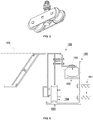
- Figure 6 shows another embodiment of the moving end 122 of the second section 120.
- Figure 6 shows a cross-section of the second section 120 in order to illustrate the moving end 122 and its support system 150 in more detail.
- the support system 150 in this case is L-shaped with a vertical part for fastening onto a wall or other structure support using suitable screws 151 and with a horizontal part.
- the vertical part there is a U-shaped support guide 152, whereas the horizontal part comprises a rail 153 that can be mounted onto the horizontal part or can be formed integrally to the support system 150.
- the moving end 122 comprises some first travel means 154 that are guided by the rail 153 and which have a profile complementary to the rail and second travel means 155 that are guided by the support guide 152 and which engage with the U-shaped support guide. Therefore, the support guide 152 and the rail 153 represent complementary support elements to the first and second travel means 153 and 155.
- the first and second travel means 154, 155 are preferably wheels. These may be in each case a single wheel, although it is better that there are at least two wheels in order to provide more stability to the solar protection system 100. There may also be more than two wheels, for example three, four, five or more along the width of the moving end depending on the size of the solar protection system
- the first travel means 154 are embedded in the moving end 122, protruding only a small amount from the travel means in order to allow movement of the pergola without friction between the second section 120 and the support system 150.
- the support 150 provides more stability and safety to the entire solar protection system by its double support 152, 153 to the travel means 154, 155, which reduces undesired movements of the pergola due to wind or accidental knocks. It allows at the same time reducing the space required for fixing the second section 120 to a wall or other support structure. It is thus the preferred support if the solar protection system comprises more than one pergola.
- the material of the solar protection system 100 is variable and it is possible to combine different materials. However, preferably a single material is used for the sections and the slats.
- Useful materials for the sections may be heat-stable plastic, wood, aluminum or other metallic materials.
- Useful materials for the slats may be heat-stable plastic, wood, aluminum or other metallic materials and even stone. Due to its availability, price and properties aluminum is preferred as the material of choice.
- Figure 7 shows another embodiment of the solar protection system according to the invention.
- the system comprises a first mobile pergola 100, for example such as described in the context of Figure 1 .
- the system comprises a second pergola 200 that is formed in the same manner as the first pergola, that is, it comprises a first vertical section and a second section coupled to the first section at an angle of at least 90o, each section comprising a moving end and a connecting end and comprising the same travel means as the first pergola.
- the angle between the first vertical section and the second section of the second pergola is the same as the angle of the first pergola, although it may also be greater.
- the second pergola is larger than the first pergola in order to be able to place the second pergola over the first pergola. It is thus possible to protect an entire surface, such as for example a terrace, from the sun, or to protect only part of it in a flexible manner, depending on the path of the sun.
- the solar protection system may comprise even more than two moveable pergolas, for example, three, four or five moveable pergolas.
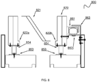
- the Fig. 8 embodiment refers to a movable pergola wherein only the horizontal section thereof is movable. That is, the vertical section is fixed, whereas the horizontal section may be moved along the vertical section in order to provide protection against the sun during the whole day.
- the solar protection system 800 comprises a horizontal section 820, wherein travel means are provided in both ends 822a and 822b.
- the travel means may be any of the travel means described before in any combination.
- Fig. 8 shows one example wherein travel means corresponding to the Fig. 6 example have been used.
- the system 800 may also comprise all the other features of the movable pergola describe before, such as the materials or the slants. That is, all the embodiments described with respect to Figs. 1 to 7 may apply also to the Fig. 8 embodiment.
- the horizontal section 820 may comprise first travel means 854 at both ends that are guided each by a rail 853 with complementary profile to the travel means.
- Each rail is mounted on a support system, for example, the support system 150 illustrated in Fig. 6 . Therefore, in this embodiment, two such support systems 150 are necessary in order to allow the movement of the horizontal section.
- These support systems can be easily mounted on any house or other walls or base structures for a pergola.
- the horizontal section 820 may further comprise optional second travel means guided by a U-shaped support guide in order to provide better stability and safety of the system.
- the system 800 comprises first and second travel means.
- the first travel means 854 are embedded in the horizontal section 820, so that only a small part protrudes in order to allow a movement without friction between the horizontal section 820 and the support system, such as support system 150.
- the second travel means and the U-shaped support guide may also be swapped. That is, the U-shaped support guide 861 may be mounted to the horizontal section 820 and the second travel means 862 may then be fastened to the support system and/or to the vertical section.
- the second travel means 862 are arranged so that they point upwards, whereas the U-shaped support guide 861 is arranged so that the U is upside down in order to place the horizontal section 820 easily on top of the second travel means 862.
- the second travel means 862 may be a rail or a plurality of wheels arranged along the whole width of the vertical support structure.
- a further safety element 863 is mounted adjacent the second travel means 862 for preventing any undesired movement or derailing of the horizontal section 820.
- said safety element 863 is L-shaped in order to overlap or overlap substantially with the support guide 861 preventing thus any lateral or vertical movement of the horizontal section 820.
Description
- This invention relates to a mobile solar protection system and, in particular, a moveable pergola comprising a first vertical section and a second section coupled to the first vertical section at an angle of at least 90º.
- Solar protection is currently very important, since the ultraviolet rays in sunlight may cause skin burns and even cancer in the long term. In the state of the art there are several solar protection systems for doors, windows or terraces. For example, there are known systems such as awnings or blinds with or without mobile slats.
- Other solar protection systems are pergolas that are usually formed by vertical columns that bear longitudinal and/or transverse beams to form an open grid. Pergolas are usually combined with climbing plants so that they create a canopy over the open grid and provide more solar protection. Pergolas are used to protect terraces, plazas or paths in a park, for example.
- Pergolas are not built on buildings, since in these cases awnings are used for solar protection. However, the problem with awnings is that in principle they only protect from the sun from above but not from the sides.
- However, all these solar protection systems have the disadvantage that they are designed to protect a certain surface for a certain time because they are fixed with respect to the sun, and they therefore loose effectiveness with the movement of the sun. Moreover, blinds have the disadvantage that they must be rolled down entirely during exposure to the sun, so that the interior is completely dark and it is necessary to turn on the light in order to be in a room. Publication
US-A-2 974 449 refers to a revolving outdoor shelter which can be rotated about a fixed axis point comprising a roof portion and a wind break portion made from a solid sheet of material. - Therefore, there is a need for a solar protection system that can provide solar protection during the entire length of the day, in particular in the summer, and that allows protecting a surface from the sun in a variable and flexible manner.
- It is the object of the invention to provide a solar protection system that allows movement of part of the system or of the entire system in order to change the area of shade depending on the path of the sun and/or the user's needs.
- To do this, at least one pergola is provided comprising travel means for the movement of part of the system or of the entire pergola in a specific direction changing thus the area of shade. For large surfaces it is possible that the system may comprise more than one pergola in order to offer solar protection according to the needs, at the same time maintaining maximum flexibility.
- The pergola further comprises two sections that protect from the sun via a plurality of slats that are fixed to each section. One section is vertical, whereas the other section is horizontal or inclined. These pergolas can be assembled directly on buildings or they can be assembled with an additional support system that allows movement of the horizontal or inclined section.
- Hence, some or all of the aforementioned problems in the state of the art are resolved. Preferred embodiments are protected by the dependent claims.
-
-
Figure 1 shows, as an example, a solar protection system according to the invention. -
Figure 2 shows, as an example, the coupling between the two sections of a solar protection system according to the invention -
Figures 3A and 3B show, as an example, slats for solar protection. -
Figures 4A - 4C show, as an example, rail profiles for the travel means. -
Figure 5 shows, as an example, wheels for the travel means. -
Figure 6 shows one way of fastening the solar protection system to a wall or other support. -
Figure 7 shows, as an example, an alternative solar protection system according to the invention. -
Figure 8 shows an example solar protection system wherein only the horizontal part thereof comprises travel means. - This invention refers to a moveable solar protection system that allows easily changing the area of shade provided by the system according to the movement of the sun. In order to do so, the system comprises travel means on a first and/or second end in order to perform a lateral travel. The invention is described below in more detail with respect to the attached drawings.
- The solar protection system according to the invention comprises at least one mobile pergola. In other aspects according to the invention it can comprise more than one pergola in order to offer more solar protection according to the user's needs, for example two, three, four, five or more pergolas. The area of shade may thus be extended in a flexible manner. These pergolas may have the same dimensions or they can be gradually increased in size in order to allow an overlap between the pergolas so that they can all be stored in one single place: That is, they are moved to a common place one above the other when they are not required.
- The pergola comprises a first vertical section and a second section that is coupled to the first section at an angle of at least 90º with respect to the first vertical section. Therefore, the second section may be horizontal in one aspect or inclined in other aspects of this invention. For example, the angle with respect to the first vertical section may vary between 90º and 135º. Preferably, the second section is horizontal (i.e. parallel to the floor) the first and second sections forming an angle of 90º, since this allows for an easier assembly.
- For example,
Figure 1 shows in a non-limiting manner asolar protection system 100 according to the invention with a firstvertical section 110 and asecond section 120 that is coupled to the first section at a 90º angle. - Each
section first end 112, 122 comprising travel means 113, 123, that is, the moving end, and asecond end sections section slats - The frame comprises at least two lateral beams that are parallel to one another and on which the plurality of
slats end sections sections - The two connecting
ends vertical section 110 to thesecond section 120. These mounting means may comprise for example screws with nuts, threaded screws or nails and the corresponding openings for a strong or secure fastening. The preferred manner of coupling the two sections is via threaded screws. -
Figure 2 shows as an example one alternative of a coupling between the first andsecond sections first section 110 and the connectingends second sections ends screws 130 that provide the necessary fastening and stability so that the twosections screws 130 may vary depending on the size of thesections - In a particular aspect, the
system 100 comprises one single beam that connects the twosections ends vertical section 110 or to thesecond section 120. Therefore, in one aspect the shared beam is part of the firstvertical section 110, whereas in other aspects it is part of thesecond section 120. By doing so, one beam is saved is saved from one of the frames and the assembly of theentire system 100 is easier. In the aspects in which the firstvertical section 110 and thesecond section 120 form a 90º angle it may be an L-shaped shared beam which on both ends of the L comprise the assembling means to couple it to the two first 110 and second 120 sections. Alternatively, the shared beam has a rectangular shape that has a first side coupled to the firstvertical section 110 and a second side, which is contiguous to the first side, coupled to thesecond section 120. And in still another alternative, the shared beam has a triangular shape to facilitate an inclination between thefirst section 110 and thesecond section 120. The triangular shape is adapted depending on the desired inclination. For reasons of assembly it is easier when the shared beam is comprised within the frame of the firstvertical section 110. - The plurality of
slats sections - The
slats vertical section 110 with a vertical configuration in thesecond section 120. Any combination is possible. Even two different configurations may be combined in a same section if so desired for aesthetic reasons. - According to the invention both
sections vertical section 110, whereas thesecond section 120 comprises fixed slats. - In some aspects of this invention, the slats may have an ellipsoidal shape, as shown as an example in
Fig. 3A , whereas in other aspects the slats may have a trapezoidal shape with a wing of just a few centimeters, for example between 2 and 5 centimeters on each end in order to provide more solar protection, as shown as an example inFig. 3B . In any case, the slats are mounted onto the frame with common fixing means (not shown), such as for example nails, screws, nuts or others. - The trapezoidal-shaped slats are preferred because they comprise three
openings 140 for their mounting with screws. The advantage of the three openings with respect to two openings as in the case of ellipsoidal-shaped slats lies in a better fastening of the slats and therefore less movement thereof due to movement of the pergola or the wind. Also, if a screw breaks for any reason during assembly of the slats, there are still two more openings with which to fasten the slat. - It has been explained above that each frame has a moving
end 112, 122. This movingend 112, 122 comprises travel means 113, 123 that allow lateral travel of theentire pergola 100 as viewed by an observer placed in front of the pergola and which therefore moves towards the left or towards the right for the observer. - The travel means 113 of the first
vertical section 110 may be the same as the travel means 123 of thesecond section 120 or they may be different. For example, the travel means 113 of the firstvertical section 110 may comprise one or more wheels that are fastened to the frame to allow the movement. It may be a central wheel, two wheels separated from one another along a beam on the moving end 112 or more wheels distributed along a beam on the moving end 112. The travel means may also be embedded in the beam on the moving end, protruding only a little in order to allow the movement without friction. - In order to prevent movements beyond the travel path a rail can be used to guide the travel means 113. This may be a rail with a convex profile having two protuberances on the edges of the rail between which the travel means 113 are moving. It may also be a rail with a concave profile with one protuberance in the centre in which the travel means 113, which have a corresponding complementary profile, engage.
Figures 4A and 4B show such rail profiles as an example. For example, it may be wheels with two protuberances on the edges, as shown as an example inFig. 5 , or a rail with a convex profile mounted along a beam on the moving end 112. The rail is mounted on the floor along the variable surface to be protected. - In the case of the travel means 123 of the
second section 120, these further require a support system (not shown) that fastens or supports thesecond section 120. Preferably, the support system fastens thesecond section 120 via the travel means 124. The support system can be mounted onto a structural element that supports the weight of thesolar protection system 100, for example an additional third frame, and that covers the entire path of the possible range of movement. If thesolar protection system 100 is mounted on a building, for example a private home, the support system may be on the wall of the building adjacent to the area to be protected. The support system comprises at least one mounting element that allows it to be fixed to the structural element, and a fastening element that allows coupling and supporting or fastening thesecond section 120 of thesolar protection system 100. Preferably, the fastening element also allows the movement of thesolar protection system 100. - In one aspect according to the invention, the travel means 124 of the
second section 120 may be a combination of wheels and rails or a combination of rails with complementary profiles. For example, they may be the same wheels and complementary rails that are used as travel means 114 for the firstvertical section 110. - However, for better fastening and security, it is preferable for the rail to have a hollow shape allowing the introduction of the wheels in the hollow space and the movement inside the rail, as shown as an example in the profile of
Figure 4C . This rail is called here hollow rail which comprises on one first side 301 a surface upon which the wheels travel, anopening 302 on asecond side 303 opposite the first side in order to allow movement of the wheels, and third 304 and fourth 305 sides that are perpendicular to the first 301 and second 303 sides and which have the appropriate dimensions to house the wheels. The hollow rail may have a rectangular or substantially rectangular shape, but a triangular shape is also possible, wherein the second side is the opening or a curved shape in which the third and fourth sides are curved. - In another alternative aspect, wheels are used to move the
solar protection system 100 instead of the hollow rail, but a guide bar is inserted into the hollow rail and is fastened by the same and can be extended along a part of the movingend 122 or along its entirety. Then, the hollow rail may have even other shapes that depend on the shape of the guide bar and which ensure at the same time good fastening. - The
second section 120 may comprise the travel means 124 in different configurations. For example, the travel means 124 may be directed downwards such that the corresponding rail lies below thesecond section 120 and supports it. The travel means 124 may also be on the same plane as thesecond section 120 such that the corresponding rail is at the same height. Or the travel means 124 can be directed upwards such that the corresponding rail lies above thesecond section 120 and thus a hanging fastening is obtained. Preferably the hanging configuration is used since it is easier to assemble. -
Figure 6 shows another embodiment of the movingend 122 of thesecond section 120. In particular,Figure 6 shows a cross-section of thesecond section 120 in order to illustrate the movingend 122 and itssupport system 150 in more detail. Thesupport system 150 in this case is L-shaped with a vertical part for fastening onto a wall or other structure support usingsuitable screws 151 and with a horizontal part. In the vertical part there is aU-shaped support guide 152, whereas the horizontal part comprises arail 153 that can be mounted onto the horizontal part or can be formed integrally to thesupport system 150. The movingend 122 comprises some first travel means 154 that are guided by therail 153 and which have a profile complementary to the rail and second travel means 155 that are guided by thesupport guide 152 and which engage with the U-shaped support guide. Therefore, thesupport guide 152 and therail 153 represent complementary support elements to the first and second travel means 153 and 155. The first and second travel means 154, 155 are preferably wheels. These may be in each case a single wheel, although it is better that there are at least two wheels in order to provide more stability to thesolar protection system 100. There may also be more than two wheels, for example three, four, five or more along the width of the moving end depending on the size of the solar protection system - In a preferred aspect of the embodiment of
Figure 6 , the first travel means 154 are embedded in the movingend 122, protruding only a small amount from the travel means in order to allow movement of the pergola without friction between thesecond section 120 and thesupport system 150. - The
support 150 provides more stability and safety to the entire solar protection system by itsdouble support second section 120 to a wall or other support structure. It is thus the preferred support if the solar protection system comprises more than one pergola. - The material of the
solar protection system 100 is variable and it is possible to combine different materials. However, preferably a single material is used for the sections and the slats. Useful materials for the sections may be heat-stable plastic, wood, aluminum or other metallic materials. Useful materials for the slats may be heat-stable plastic, wood, aluminum or other metallic materials and even stone. Due to its availability, price and properties aluminum is preferred as the material of choice. -
Figure 7 shows another embodiment of the solar protection system according to the invention. In this case the system comprises a firstmobile pergola 100, for example such as described in the context ofFigure 1 . Moreover, the system comprises asecond pergola 200 that is formed in the same manner as the first pergola, that is, it comprises a first vertical section and a second section coupled to the first section at an angle of at least 90º, each section comprising a moving end and a connecting end and comprising the same travel means as the first pergola. The angle between the first vertical section and the second section of the second pergola is the same as the angle of the first pergola, although it may also be greater. - The second pergola is larger than the first pergola in order to be able to place the second pergola over the first pergola. It is thus possible to protect an entire surface, such as for example a terrace, from the sun, or to protect only part of it in a flexible manner, depending on the path of the sun.
- For larger spaces, it is possible that the solar protection system may comprise even more than two moveable pergolas, for example, three, four or five moveable pergolas.
- The
Fig. 8 embodiment refers to a movable pergola wherein only the horizontal section thereof is movable. That is, the vertical section is fixed, whereas the horizontal section may be moved along the vertical section in order to provide protection against the sun during the whole day. Here, thesolar protection system 800 comprises ahorizontal section 820, wherein travel means are provided in bothends Fig. 8 shows one example wherein travel means corresponding to theFig. 6 example have been used. Also, thesystem 800 may also comprise all the other features of the movable pergola describe before, such as the materials or the slants. That is, all the embodiments described with respect toFigs. 1 to 7 may apply also to theFig. 8 embodiment. - Hence, the
horizontal section 820 may comprise first travel means 854 at both ends that are guided each by arail 853 with complementary profile to the travel means. Each rail is mounted on a support system, for example, thesupport system 150 illustrated inFig. 6 . Therefore, in this embodiment, twosuch support systems 150 are necessary in order to allow the movement of the horizontal section. These support systems can be easily mounted on any house or other walls or base structures for a pergola. Thehorizontal section 820 may further comprise optional second travel means guided by a U-shaped support guide in order to provide better stability and safety of the system. Thus, in a preferred aspect, thesystem 800 comprises first and second travel means. Preferably, the first travel means 854 are embedded in thehorizontal section 820, so that only a small part protrudes in order to allow a movement without friction between thehorizontal section 820 and the support system, such assupport system 150. - According to
Fig. 8 , the second travel means and the U-shaped support guide may also be swapped. That is, theU-shaped support guide 861 may be mounted to thehorizontal section 820 and the second travel means 862 may then be fastened to the support system and/or to the vertical section. In one particular alternative, the second travel means 862 are arranged so that they point upwards, whereas theU-shaped support guide 861 is arranged so that the U is upside down in order to place thehorizontal section 820 easily on top of the second travel means 862. Such a configuration allows not only an easy and straightforward assembly, but enables also an easy adaption of already existing pergola base structures in order to place a movable section thereon. Here, the second travel means 862 may be a rail or a plurality of wheels arranged along the whole width of the vertical support structure. - Optionally, a
further safety element 863 is mounted adjacent the second travel means 862 for preventing any undesired movement or derailing of thehorizontal section 820. Preferably, saidsafety element 863 is L-shaped in order to overlap or overlap substantially with thesupport guide 861 preventing thus any lateral or vertical movement of thehorizontal section 820. - What has been described comprises several example embodiments. Since it is not possible or feasible to describe all the variations of combinations and permutations of the inventive concept that would give rise to a large number of embodiments and redundant paragraphs, it is understood that the skilled person would derive these different possible permutations and combinations of the different embodiments and aspects described after a direct and objective reading of this disclosure. Therefore, the main aspects and embodiments have been described, understanding that they comprise the remaining combinations, variations and modifications, whilst they are comprised within the scope of protection defined by the claims. The skilled person would understand that the presented description of the embodiments does not limit the invention, nor do the drawings.
Claims (15)
- A solar protection system comprising at least a first moveable pergola (100), characterized in that the first moveable pergola comprises:a first vertical section (110) with a plurality of slats (111) that protects from the sun,a second horizontal or inclined section (120) with a plurality of slats (121) that protects from the sun coupled to the first section (110) at an angle of at least 90°, andtravel means (113, 123) in the first (110) and/or second (120) section, allowing movement of the first moveable pergola (100) in a specific direction, and wherein the plurality of slats (111, 121) of each section (110, 120) are separated from one another.
- The system according to claim 1, wherein the angle between the first (110) and second (120) section varies between 90° and 135°.
- The system according to claims 1 or 2, wherein the angle between the first (110) and second (120) section is 90°.
- The system according to claims 1 to 3, wherein each section (110, 120) is formed by a frame with a moving end (112, 122) comprising the travel means (113, 123) and a connecting end (114, 124) connecting the first (110) and second (120) sections.
- The system according to claims 1 to 4, wherein the pergola (100) comprises one single beam for coupling the first section (110) to the second section (120) that is shared between the two sections and represents the connecting end (114, 124) of both the first vertical section (110) and the second section (120), said beam preferably having a rectangular shape or being L-shaped.
- The system according to claims 1 to 5, wherein the slats (111, 121) have an ellipsoidal or trapezoidal shape, preferably comprising wings on the ends.
- The system according to claims 1 to 6, wherein the slats (111, 121) are fixed or moveable.
- The system according to claims 1 to 6, wherein one section comprises fixed slats and the other section comprises moveable slats.
- The system according to claim 7 or 8, wherein the fixed slats (111, 121) have an inclination that varies between 10° and 80° with respect to the plane of the frame and comprise at least two openings (140), preferably three openings, for their mounting to the sections (110, 120).
- The system according to claims 1 to 9, wherein the travel means (113, 123) comprise wheels and rails with complementary profiles.
- The system according to claims 1 to 10, wherein the rail of the travel means (113) of the first section (110) has a convex profile, whereas the rail of the travel means (123) of the second section (120) is a hollow rail that allows the insertion of the wheels and a hanging fastening of the second section (120).
- The system according to claims 1 to 10, wherein the moving end (122) of the second section (120) comprises first and second travel means (154, 155) that engage with complementary support elements (152, 153) of a support system (150).
- The system according to claims 1 to 12, comprising a second additional moveable pergola (200) that is preferably larger than the first moveable pergola (100) in order to store them one over the other in a common place when there is no sun.
- The system according to claims 1 to 13, wherein the system is made of aluminum, wood, heat-stable plastic or a combination thereof.
- The system according to claims 1 to 14, wherein the slats are made of aluminum, wood, heat-stable plastic or a combination thereof.
Applications Claiming Priority (1)
| Application Number | Priority Date | Filing Date | Title |
|---|---|---|---|
| ES201530895U ES1142865Y (en) | 2015-07-29 | 2015-07-29 | SOLAR PROTECTION SYSTEM |
Publications (2)
| Publication Number | Publication Date |
|---|---|
| EP3124716A1 EP3124716A1 (en) | 2017-02-01 |
| EP3124716B1 true EP3124716B1 (en) | 2017-12-13 |
Family
ID=53887346
Family Applications (1)
| Application Number | Title | Priority Date | Filing Date |
|---|---|---|---|
| EP16168053.3A Active EP3124716B1 (en) | 2015-07-29 | 2016-05-03 | Solar protection system with a movable pergola |
Country Status (3)
| Country | Link |
|---|---|
| EP (1) | EP3124716B1 (en) |
| ES (2) | ES1142865Y (en) |
| PT (1) | PT3124716T (en) |
Families Citing this family (1)
| Publication number | Priority date | Publication date | Assignee | Title |
|---|---|---|---|---|
| EP3732339B1 (en) * | 2017-12-24 | 2023-08-09 | JMH Concepteur SLU | Heat and/or light regulating system |
Family Cites Families (9)
| Publication number | Priority date | Publication date | Assignee | Title |
|---|---|---|---|---|
| US2611936A (en) * | 1951-05-22 | 1952-09-30 | Everett T Wheeler | Combination shutter and awning |
| US2974449A (en) * | 1959-03-26 | 1961-03-14 | Gurny B Leeper | Revolving patio awnings |
| US3166870A (en) * | 1960-05-31 | 1965-01-26 | Porte Gordon G La | Auxiliary movable shelter |
| IT1195212B (en) * | 1981-10-01 | 1988-10-12 | Severino Dona | BELLOW TYPE PORTAL TUNNELS WITH A SUBSTANTIALLY REVERSE L-STRUCTURE |
| DE4329807A1 (en) * | 1993-09-03 | 1995-03-09 | Joerg Dipl Ing Drewes | Glazed annexe for a building |
| GB2391558B (en) * | 2002-08-01 | 2006-04-19 | Tony Bliss | Rotatable screened deck |
| US6708706B1 (en) * | 2002-08-09 | 2004-03-23 | Brenda Robinson | Retractable pool shade with support stand |
| ES2531203B1 (en) * | 2013-04-16 | 2015-12-22 | Francisco Javier MARTINEZ FRANCO | Mobile cover |
| EP2905401B1 (en) * | 2014-02-05 | 2017-03-08 | Unopiu' S.p.A. di Socio Unico | Pergola provided with extensible roof |
-
2015
- 2015-07-29 ES ES201530895U patent/ES1142865Y/en not_active Expired - Fee Related
-
2016
- 2016-05-03 ES ES16168053.3T patent/ES2659960T3/en active Active
- 2016-05-03 EP EP16168053.3A patent/EP3124716B1/en active Active
- 2016-05-03 PT PT161680533T patent/PT3124716T/en unknown
Non-Patent Citations (1)
| Title |
|---|
| None * |
Also Published As
| Publication number | Publication date |
|---|---|
| EP3124716A1 (en) | 2017-02-01 |
| ES1142865Y (en) | 2015-11-18 |
| ES1142865U (en) | 2015-08-27 |
| PT3124716T (en) | 2018-01-16 |
| ES2659960T3 (en) | 2018-03-20 |
Similar Documents
| Publication | Publication Date | Title |
|---|---|---|
| US9915062B2 (en) | Structure having convertible roof and walls | |
| NL2008069C2 (en) | SUN PROTECTION. | |
| BE1021781B1 (en) | COLUMN FOR SUPPORTING A COVER AND SCREEN CONSTRUCTION CONTAINING SUCH A COLUMN | |
| EP3015618A1 (en) | Covering apparatus | |
| EP2492433B1 (en) | Wind-up-screen | |
| EP3387198B1 (en) | Air dome with windows | |
| EP2351896B1 (en) | Column system and screen device comprising one or more such column systems | |
| EP3124716B1 (en) | Solar protection system with a movable pergola | |
| ITMI20092250A1 (en) | MOBILE SUNSCREEN SHIELDING SYSTEM WITH PERFECT STRUCTURE | |
| EP3732339B1 (en) | Heat and/or light regulating system | |
| US20200318356A1 (en) | Heat and/or light regulating system | |
| US11959283B2 (en) | Heat and/or light regulating system | |
| RU2709252C1 (en) | Section of one-side viewed enclosure | |
| EP4073326A1 (en) | Roof device for a canopy | |
| RU2786950C1 (en) | Fence-slider section | |
| ITVI20110244A1 (en) | COMPOSITE STRUCTURE OF PROTECTION AND / OR SHELF FOR THE INSTALLATION OF EXTERNAL ENVIRONMENTS | |
| DE202017002299U1 (en) | Sun protection frame as a sun, sight and wind protection device for side openings in terrace and / or awning constructions | |
| EP2708672A1 (en) | Pitch awning and method for assembling a pitch awning | |
| CA3229903A1 (en) | A terrace canopy and method for producing same | |
| CZ31939U1 (en) | A supporting element for light structures, especially pergolas | |
| AU2004100181A4 (en) | Improvements in means for joining, and closure means incorporating such | |
| CA3221526A1 (en) | A terrace canopy | |
| KR101645597B1 (en) | Blind for light inflow adjust | |
| EP3429331A1 (en) | Multifunctional extruded profiled supports for greenhouses |
Legal Events
| Date | Code | Title | Description |
|---|---|---|---|
| PUAI | Public reference made under article 153(3) epc to a published international application that has entered the european phase |
Free format text: ORIGINAL CODE: 0009012 |
|
| AK | Designated contracting states |
Kind code of ref document: A1 Designated state(s): AL AT BE BG CH CY CZ DE DK EE ES FI FR GB GR HR HU IE IS IT LI LT LU LV MC MK MT NL NO PL PT RO RS SE SI SK SM TR |
|
| AX | Request for extension of the european patent |
Extension state: BA ME |
|
| 17P | Request for examination filed |
Effective date: 20170310 |
|
| RBV | Designated contracting states (corrected) |
Designated state(s): AL AT BE BG CH CY CZ DE DK EE ES FI FR GB GR HR HU IE IS IT LI LT LU LV MC MK MT NL NO PL PT RO RS SE SI SK SM TR |
|
| 17Q | First examination report despatched |
Effective date: 20170519 |
|
| GRAP | Despatch of communication of intention to grant a patent |
Free format text: ORIGINAL CODE: EPIDOSNIGR1 |
|
| RIC1 | Information provided on ipc code assigned before grant |
Ipc: E04F 10/10 20060101ALI20170915BHEP Ipc: E04F 10/08 20060101AFI20170915BHEP Ipc: E04H 15/58 20060101ALI20170915BHEP Ipc: E04B 1/343 20060101ALI20170915BHEP |
|
| GRAS | Grant fee paid |
Free format text: ORIGINAL CODE: EPIDOSNIGR3 |
|
| INTG | Intention to grant announced |
Effective date: 20171013 |
|
| GRAA | (expected) grant |
Free format text: ORIGINAL CODE: 0009210 |
|
| STAA | Information on the status of an ep patent application or granted ep patent |
Free format text: STATUS: THE PATENT HAS BEEN GRANTED |
|
| REG | Reference to a national code |
Ref country code: GB Ref legal event code: FG4D |
|
| REG | Reference to a national code |
Ref country code: AT Ref legal event code: REF Ref document number: 954514 Country of ref document: AT Kind code of ref document: T Effective date: 20171215 Ref country code: CH Ref legal event code: EP |
|
| REG | Reference to a national code |
Ref country code: IE Ref legal event code: FG4D |
|
| REG | Reference to a national code |
Ref country code: PT Ref legal event code: SC4A Ref document number: 3124716 Country of ref document: PT Date of ref document: 20180116 Kind code of ref document: T Free format text: AVAILABILITY OF NATIONAL TRANSLATION Effective date: 20171214 |
|
| REG | Reference to a national code |
Ref country code: DE Ref legal event code: R096 Ref document number: 602016001062 Country of ref document: DE |
|
| REG | Reference to a national code |
Ref country code: ES Ref legal event code: FG2A Ref document number: 2659960 Country of ref document: ES Kind code of ref document: T3 Effective date: 20180320 |
|
| REG | Reference to a national code |
Ref country code: NL Ref legal event code: MP Effective date: 20171213 |
|
| PG25 | Lapsed in a contracting state [announced via postgrant information from national office to epo] |
Ref country code: FI Free format text: LAPSE BECAUSE OF FAILURE TO SUBMIT A TRANSLATION OF THE DESCRIPTION OR TO PAY THE FEE WITHIN THE PRESCRIBED TIME-LIMIT Effective date: 20171213 Ref country code: NO Free format text: LAPSE BECAUSE OF FAILURE TO SUBMIT A TRANSLATION OF THE DESCRIPTION OR TO PAY THE FEE WITHIN THE PRESCRIBED TIME-LIMIT Effective date: 20180313 Ref country code: SE Free format text: LAPSE BECAUSE OF FAILURE TO SUBMIT A TRANSLATION OF THE DESCRIPTION OR TO PAY THE FEE WITHIN THE PRESCRIBED TIME-LIMIT Effective date: 20171213 |
|
| REG | Reference to a national code |
Ref country code: FR Ref legal event code: PLFP Year of fee payment: 3 |
|
| REG | Reference to a national code |
Ref country code: AT Ref legal event code: MK05 Ref document number: 954514 Country of ref document: AT Kind code of ref document: T Effective date: 20171213 |
|
| PG25 | Lapsed in a contracting state [announced via postgrant information from national office to epo] |
Ref country code: LV Free format text: LAPSE BECAUSE OF FAILURE TO SUBMIT A TRANSLATION OF THE DESCRIPTION OR TO PAY THE FEE WITHIN THE PRESCRIBED TIME-LIMIT Effective date: 20171213 Ref country code: GR Free format text: LAPSE BECAUSE OF FAILURE TO SUBMIT A TRANSLATION OF THE DESCRIPTION OR TO PAY THE FEE WITHIN THE PRESCRIBED TIME-LIMIT Effective date: 20180314 Ref country code: HR Free format text: LAPSE BECAUSE OF FAILURE TO SUBMIT A TRANSLATION OF THE DESCRIPTION OR TO PAY THE FEE WITHIN THE PRESCRIBED TIME-LIMIT Effective date: 20171213 Ref country code: BG Free format text: LAPSE BECAUSE OF FAILURE TO SUBMIT A TRANSLATION OF THE DESCRIPTION OR TO PAY THE FEE WITHIN THE PRESCRIBED TIME-LIMIT Effective date: 20180313 Ref country code: RS Free format text: LAPSE BECAUSE OF FAILURE TO SUBMIT A TRANSLATION OF THE DESCRIPTION OR TO PAY THE FEE WITHIN THE PRESCRIBED TIME-LIMIT Effective date: 20171213 |
|
| PG25 | Lapsed in a contracting state [announced via postgrant information from national office to epo] |
Ref country code: NL Free format text: LAPSE BECAUSE OF FAILURE TO SUBMIT A TRANSLATION OF THE DESCRIPTION OR TO PAY THE FEE WITHIN THE PRESCRIBED TIME-LIMIT Effective date: 20171213 |
|
| PG25 | Lapsed in a contracting state [announced via postgrant information from national office to epo] |
Ref country code: CY Free format text: LAPSE BECAUSE OF FAILURE TO SUBMIT A TRANSLATION OF THE DESCRIPTION OR TO PAY THE FEE WITHIN THE PRESCRIBED TIME-LIMIT Effective date: 20171213 Ref country code: EE Free format text: LAPSE BECAUSE OF FAILURE TO SUBMIT A TRANSLATION OF THE DESCRIPTION OR TO PAY THE FEE WITHIN THE PRESCRIBED TIME-LIMIT Effective date: 20171213 Ref country code: SK Free format text: LAPSE BECAUSE OF FAILURE TO SUBMIT A TRANSLATION OF THE DESCRIPTION OR TO PAY THE FEE WITHIN THE PRESCRIBED TIME-LIMIT Effective date: 20171213 Ref country code: CZ Free format text: LAPSE BECAUSE OF FAILURE TO SUBMIT A TRANSLATION OF THE DESCRIPTION OR TO PAY THE FEE WITHIN THE PRESCRIBED TIME-LIMIT Effective date: 20171213 |
|
| PG25 | Lapsed in a contracting state [announced via postgrant information from national office to epo] |
Ref country code: PL Free format text: LAPSE BECAUSE OF FAILURE TO SUBMIT A TRANSLATION OF THE DESCRIPTION OR TO PAY THE FEE WITHIN THE PRESCRIBED TIME-LIMIT Effective date: 20171213 Ref country code: SM Free format text: LAPSE BECAUSE OF FAILURE TO SUBMIT A TRANSLATION OF THE DESCRIPTION OR TO PAY THE FEE WITHIN THE PRESCRIBED TIME-LIMIT Effective date: 20171213 Ref country code: AT Free format text: LAPSE BECAUSE OF FAILURE TO SUBMIT A TRANSLATION OF THE DESCRIPTION OR TO PAY THE FEE WITHIN THE PRESCRIBED TIME-LIMIT Effective date: 20171213 Ref country code: IS Free format text: LAPSE BECAUSE OF FAILURE TO SUBMIT A TRANSLATION OF THE DESCRIPTION OR TO PAY THE FEE WITHIN THE PRESCRIBED TIME-LIMIT Effective date: 20180413 Ref country code: RO Free format text: LAPSE BECAUSE OF FAILURE TO SUBMIT A TRANSLATION OF THE DESCRIPTION OR TO PAY THE FEE WITHIN THE PRESCRIBED TIME-LIMIT Effective date: 20171213 |
|
| REG | Reference to a national code |
Ref country code: DE Ref legal event code: R097 Ref document number: 602016001062 Country of ref document: DE |
|
| PLBE | No opposition filed within time limit |
Free format text: ORIGINAL CODE: 0009261 |
|
| STAA | Information on the status of an ep patent application or granted ep patent |
Free format text: STATUS: NO OPPOSITION FILED WITHIN TIME LIMIT |
|
| 26N | No opposition filed |
Effective date: 20180914 |
|
| PG25 | Lapsed in a contracting state [announced via postgrant information from national office to epo] |
Ref country code: DK Free format text: LAPSE BECAUSE OF FAILURE TO SUBMIT A TRANSLATION OF THE DESCRIPTION OR TO PAY THE FEE WITHIN THE PRESCRIBED TIME-LIMIT Effective date: 20171213 |
|
| REG | Reference to a national code |
Ref country code: BE Ref legal event code: MM Effective date: 20180531 |
|
| PG25 | Lapsed in a contracting state [announced via postgrant information from national office to epo] |
Ref country code: MC Free format text: LAPSE BECAUSE OF FAILURE TO SUBMIT A TRANSLATION OF THE DESCRIPTION OR TO PAY THE FEE WITHIN THE PRESCRIBED TIME-LIMIT Effective date: 20171213 |
|
| REG | Reference to a national code |
Ref country code: IE Ref legal event code: MM4A |
|
| PG25 | Lapsed in a contracting state [announced via postgrant information from national office to epo] |
Ref country code: SI Free format text: LAPSE BECAUSE OF FAILURE TO SUBMIT A TRANSLATION OF THE DESCRIPTION OR TO PAY THE FEE WITHIN THE PRESCRIBED TIME-LIMIT Effective date: 20171213 |
|
| PG25 | Lapsed in a contracting state [announced via postgrant information from national office to epo] |
Ref country code: LU Free format text: LAPSE BECAUSE OF NON-PAYMENT OF DUE FEES Effective date: 20180503 |
|
| PG25 | Lapsed in a contracting state [announced via postgrant information from national office to epo] |
Ref country code: IE Free format text: LAPSE BECAUSE OF NON-PAYMENT OF DUE FEES Effective date: 20180503 |
|
| PG25 | Lapsed in a contracting state [announced via postgrant information from national office to epo] |
Ref country code: BE Free format text: LAPSE BECAUSE OF NON-PAYMENT OF DUE FEES Effective date: 20180531 |
|
| REG | Reference to a national code |
Ref country code: CH Ref legal event code: PL |
|
| PG25 | Lapsed in a contracting state [announced via postgrant information from national office to epo] |
Ref country code: LI Free format text: LAPSE BECAUSE OF NON-PAYMENT OF DUE FEES Effective date: 20190531 Ref country code: MT Free format text: LAPSE BECAUSE OF NON-PAYMENT OF DUE FEES Effective date: 20180503 Ref country code: CH Free format text: LAPSE BECAUSE OF NON-PAYMENT OF DUE FEES Effective date: 20190531 |
|
| PG25 | Lapsed in a contracting state [announced via postgrant information from national office to epo] |
Ref country code: TR Free format text: LAPSE BECAUSE OF FAILURE TO SUBMIT A TRANSLATION OF THE DESCRIPTION OR TO PAY THE FEE WITHIN THE PRESCRIBED TIME-LIMIT Effective date: 20171213 |
|
| PG25 | Lapsed in a contracting state [announced via postgrant information from national office to epo] |
Ref country code: LT Free format text: LAPSE BECAUSE OF FAILURE TO SUBMIT A TRANSLATION OF THE DESCRIPTION OR TO PAY THE FEE WITHIN THE PRESCRIBED TIME-LIMIT Effective date: 20171213 Ref country code: HU Free format text: LAPSE BECAUSE OF FAILURE TO SUBMIT A TRANSLATION OF THE DESCRIPTION OR TO PAY THE FEE WITHIN THE PRESCRIBED TIME-LIMIT; INVALID AB INITIO Effective date: 20160503 Ref country code: MK Free format text: LAPSE BECAUSE OF NON-PAYMENT OF DUE FEES Effective date: 20171213 |
|
| PG25 | Lapsed in a contracting state [announced via postgrant information from national office to epo] |
Ref country code: AL Free format text: LAPSE BECAUSE OF FAILURE TO SUBMIT A TRANSLATION OF THE DESCRIPTION OR TO PAY THE FEE WITHIN THE PRESCRIBED TIME-LIMIT Effective date: 20171213 |
|
| GBPC | Gb: european patent ceased through non-payment of renewal fee |
Effective date: 20200503 |
|
| PG25 | Lapsed in a contracting state [announced via postgrant information from national office to epo] |
Ref country code: GB Free format text: LAPSE BECAUSE OF NON-PAYMENT OF DUE FEES Effective date: 20200503 |
|
| P01 | Opt-out of the competence of the unified patent court (upc) registered |
Effective date: 20230602 |
|
| PGFP | Annual fee paid to national office [announced via postgrant information from national office to epo] |
Ref country code: PT Payment date: 20230417 Year of fee payment: 8 Ref country code: IT Payment date: 20230508 Year of fee payment: 8 Ref country code: FR Payment date: 20230417 Year of fee payment: 8 Ref country code: ES Payment date: 20230601 Year of fee payment: 8 Ref country code: DE Payment date: 20230417 Year of fee payment: 8 |