EP2989451B1 - Ct-röntgenprüfanlage, insbesondere zur inspektion von objekten - Google Patents
Ct-röntgenprüfanlage, insbesondere zur inspektion von objekten Download PDFInfo
- Publication number
- EP2989451B1 EP2989451B1 EP14720571.0A EP14720571A EP2989451B1 EP 2989451 B1 EP2989451 B1 EP 2989451B1 EP 14720571 A EP14720571 A EP 14720571A EP 2989451 B1 EP2989451 B1 EP 2989451B1
- Authority
- EP
- European Patent Office
- Prior art keywords
- detector
- ray
- detector elements
- rotation
- inspection
- Prior art date
- Legal status (The legal status is an assumption and is not a legal conclusion. Google has not performed a legal analysis and makes no representation as to the accuracy of the status listed.)
- Active
Links
Images


Classifications
-
- G—PHYSICS
- G01—MEASURING; TESTING
- G01N—INVESTIGATING OR ANALYSING MATERIALS BY DETERMINING THEIR CHEMICAL OR PHYSICAL PROPERTIES
- G01N23/00—Investigating or analysing materials by the use of wave or particle radiation, e.g. X-rays or neutrons, not covered by groups G01N3/00 – G01N17/00, G01N21/00 or G01N22/00
- G01N23/02—Investigating or analysing materials by the use of wave or particle radiation, e.g. X-rays or neutrons, not covered by groups G01N3/00 – G01N17/00, G01N21/00 or G01N22/00 by transmitting the radiation through the material
- G01N23/06—Investigating or analysing materials by the use of wave or particle radiation, e.g. X-rays or neutrons, not covered by groups G01N3/00 – G01N17/00, G01N21/00 or G01N22/00 by transmitting the radiation through the material and measuring the absorption
- G01N23/083—Investigating or analysing materials by the use of wave or particle radiation, e.g. X-rays or neutrons, not covered by groups G01N3/00 – G01N17/00, G01N21/00 or G01N22/00 by transmitting the radiation through the material and measuring the absorption the radiation being X-rays
-
- G—PHYSICS
- G01—MEASURING; TESTING
- G01T—MEASUREMENT OF NUCLEAR OR X-RADIATION
- G01T1/00—Measuring X-radiation, gamma radiation, corpuscular radiation, or cosmic radiation
- G01T1/29—Measurement performed on radiation beams, e.g. position or section of the beam; Measurement of spatial distribution of radiation
- G01T1/2914—Measurement of spatial distribution of radiation
- G01T1/2985—In depth localisation, e.g. using positron emitters; Tomographic imaging (longitudinal and transverse section imaging; apparatus for radiation diagnosis sequentially in different planes, steroscopic radiation diagnosis)
-
- A—HUMAN NECESSITIES
- A61—MEDICAL OR VETERINARY SCIENCE; HYGIENE
- A61B—DIAGNOSIS; SURGERY; IDENTIFICATION
- A61B6/00—Apparatus or devices for radiation diagnosis; Apparatus or devices for radiation diagnosis combined with radiation therapy equipment
- A61B6/02—Arrangements for diagnosis sequentially in different planes; Stereoscopic radiation diagnosis
- A61B6/03—Computed tomography [CT]
- A61B6/032—Transmission computed tomography [CT]
-
- A—HUMAN NECESSITIES
- A61—MEDICAL OR VETERINARY SCIENCE; HYGIENE
- A61B—DIAGNOSIS; SURGERY; IDENTIFICATION
- A61B6/00—Apparatus or devices for radiation diagnosis; Apparatus or devices for radiation diagnosis combined with radiation therapy equipment
- A61B6/40—Arrangements for generating radiation specially adapted for radiation diagnosis
- A61B6/4007—Arrangements for generating radiation specially adapted for radiation diagnosis characterised by using a plurality of source units
-
- A—HUMAN NECESSITIES
- A61—MEDICAL OR VETERINARY SCIENCE; HYGIENE
- A61B—DIAGNOSIS; SURGERY; IDENTIFICATION
- A61B6/00—Apparatus or devices for radiation diagnosis; Apparatus or devices for radiation diagnosis combined with radiation therapy equipment
- A61B6/48—Diagnostic techniques
- A61B6/482—Diagnostic techniques involving multiple energy imaging
Definitions
- the invention relates generally to an X-ray inspection system.
- the invention relates in particular to an X-ray inspection system for the non-destructive inspection of objects.
- DE 101 49 254 A1 shows an X-ray inspection system with several fixed radiation planes for the inspection of objects, for example for the security check of luggage at airports.
- the inspection object is conveyed through several radiation levels, each of which is emitted by a stationary radiation source.
- the intensities of the unabsorbed rays are measured and evaluated by the detector arrangements assigned to the radiation sources.
- US 7 362 847 B2 shows an X-ray inspection system of the type of a computer tomograph (CT) with a rotating gantry which is also used for object inspection.
- CT computer tomograph
- U.S. 5,361,291 A also shows a CT device in which the focal point of the X-ray tube can be moved translationally in order to double the spatial scanning rate compared to a conventional CT device in order to reduce aliasing in the reconstructed X-ray images.
- EP 0 231 037 A1 shows an X-ray scanner with an arrangement of detectors and an X-ray tube with an elongated anode or double focus.
- the X-ray scanner can be operated in different modes, with all detector signals being evaluated separately in an unpaired mode, signals from two adjacent detectors being evaluated in combination in a paired mode, and different spectral filters being assigned to adjacent detectors in a dual-energy mode.
- US 7 778 383 B2 shows a similar CT system for measuring dual-energy X-ray attenuation data of an object with an X-ray source with two different focal points and a detection device with a plurality of first and second detector elements alternating in the circumferential direction, with adjacent elements each having different spectral sensitivities.
- the object is first irradiated by X-rays from the first focal point in order to acquire first attenuation data with the first detector elements and the second detector elements. Then the object of X-rays of the second Radiated through the focus point in order to detect second attenuation data with the first and second detector elements.
- the two focal points are spatially separated from each other in such a way that a first beam path from the first focal point penetrates a certain voxel within the object and hits a first detector element and a second beam path from the second focal point penetrates the same voxel and hits an adjacent second detector element.
- X-ray inspection systems for the inspection of objects, especially for the detection of hazardous substances, are constantly advancing with regard to an increase in baggage throughput with, of course, the same high detection rate, i.e. detection reliability.
- X-ray inspection systems of the computed tomography (CT) type are very complex devices.
- the detector units required in CT devices particularly in the case of CTs with dual-energy functionality, are very expensive and, due to the high packing density of detector elements required for the desired resolutions, are complicated and therefore expensive.
- Fig. 10 shows CT methods and a CT system for measuring dual-energy X-ray attenuation data of an inspection object.
- the CT system comprises a rotatable holder, an X-ray source with two different X-ray focus points and an X-ray detection device with a plurality of first and second detector elements of different spectral sensitivity, which are arranged alternately in the direction of rotation of the holder without gaps.
- the following steps are carried out in the operation of the CT system or the execution of the method.
- the first and second focal points are spatially separated from one another in such a way that a first beam path starting from the first focal point passes through a specific voxel within the object and hits a first detector element, while a second beam path starting from the second focal point penetrates and onto the same voxel hits a second detector element.
- WO 2012/112153 A1 shows a CT method and systems with a detector array that has an effective size that is larger than the actual size of the Detector elements of the detector arrangement.
- a so-called sparse array is proposed, in which one or more channels of the detector array are omitted so that there are gaps between the detector elements in the direction of rotation of the detector arrangement.
- Similar to the WO 2012/112153 A1 show WO 2012/112153 A1 and WO 2013/126649 A2 also detector arrangement with sparse arrays.
- U.S. 5,841,832 A and WO 2006/114716 A2 show dual-energy X-ray devices which have so-called dual-energy X-ray detectors in which two types of detector elements, each designed for the detection of high or low energy X-rays, are arranged next to or one above the other.
- a core idea of the invention lies in the knowledge that in an X-ray inspection system with a rotating radiation source and with (i) a detector unit arranged opposite to rotate with it or with (ii) an annular detector unit arranged in a stationary manner around the circular path described by the rotating radiation source, by increasing the number the radiation sources, for example the X-ray focal points (foci), to reduce the number of detector elements required in the circumferential direction of the rotation.
- the fill factor (ratio of the sensitive area to the total area) of the detector unit and / or the detector elements can be reduced compared to the known X-ray inspection systems. For example, increasing the number of radiation sources from one to two, ie doubling, at least halving the number of detector elements required on the detector unit in the direction of rotation.
- the inventors first recognized that if the distance (in the direction of rotation) between the at least two radiation sources is set in the order of magnitude of the width of a detector element, the distance between the detector elements in the circumferential direction of the rotation increases to at least the width of a detector element without affecting the resolution can be. In other words, every second detector element can be eliminated.
- the structure of the detector elements or the detector unit can advantageously be simplified due to the space freed up in the detector unit.
- a gap with the width of a detector element is then located between two adjacent detector elements. This gap is also available, for example, for wiring the detector elements.
- the simplified X-ray inspection system enables X-ray recordings to be made which have the same quality, in particular the same resolution, as X-ray recordings made with a comparable X-ray inspection system with only one radiation source and the usual high number of detector elements that are arranged on the detector unit without any gaps in the circumferential direction , were made.
- the inventors have further recognized that if the distance between the at least two radiation sources is set in the order of magnitude of the width of a detector element, the distance between the detector elements in the circumferential direction of the rotation is up to twice, possibly up to 2.5 times Width of a detector element can be increased. However, this enlargement of the gaps then results in a reduction in the quality of the X-ray images. This means that the gap width can be adjusted accordingly to the specified extent with regard to a required quality, in particular resolution, of the x-ray images. As a result, even more than half of the detector elements of a detector unit with a 100% fill factor can be saved. That is to say, with the additional expenditure for the second or further x-ray sources or foci, a corresponding reduction in the expenditure for the detector unit can be achieved in addition to additional advantages. An X-ray inspection system according to the invention is therefore more cost-effective.
- An X-ray inspection system for the non-destructive inspection of objects can thus have: at least two X-ray sources (also known as foci or focal spots) rotatable about an axis of rotation in a plane of rotation for generating a beam of rays passing through an examination area and a detector unit with detector elements arranged opposite the at least one X-ray source X-rays.
- An inspection object can be conveyed through the examination area by means of a transport device along a conveying direction, the conveying direction for the inspection object running essentially perpendicular to the plane of rotation.
- Detector elements which are adjacent to one another in the circumferential direction of the rotation of the X-ray sources are spaced apart by a first distance D1 in such a way that they form a gap; i.e. the fill factor of the detector unit is less than 100%.
- the at least two independently controllable x-ray sources (foci) are arranged at a second distance D2 in the circumferential direction in the plane of rotation.
- the at least two independently controllable X-ray sources are preferably spaced apart such that along a first straight line that runs (a) through the center of rotation of the foci and (b) perpendicular to a second straight line that (i) from the point on the rotational path of the foci , which lies in the middle between the two foci, and (ii) runs through the center of rotation of the foci, at least in a section around the center of rotation results in a desired spatial resolution through the combination of the two foci with the spaced detector elements of the detector unit.
- this section of the first straight line essentially corresponds to the examination area or measuring field of the X-ray inspection system.
- the section of the first straight line that forms the measurement field can be interpreted as a virtual detector which has the required or required spatial resolution. Due to the gaps between the detector elements, a system-related effect is initially additionally reinforced in CT systems, namely that oversampling takes place in the semicircle of the foci above the virtual detector towards the foci and undersampling takes place in the semicircle below the virtual detector towards the detector elements. Since the arrangement of the at least two x-ray sources and the detector unit rotates around the inspection object, the undersampling and oversampling are balanced out and the resolution of the virtual detector is achieved for the inspection object.
- the ratio D1 / B of the first distance D1 to a width B of a first detector element in the circumferential direction is more than 100% and at most 250% due to the gaps. Ie the gap is larger than the width B and a maximum of 2.5 times the width B of a detector element.
- the ratio D1 / B of the first distance D1 to the width B of a first detector element in the circumferential direction can in certain embodiments be at least more than 110%, or more than 125%, or more than 150%, or more than 175% or more than 200%. be.
- the structure of the detector unit is simplified by the gaps.
- the gaps between the detector columns can be used for wiring the detector elements. Since there is more space available for the detector elements in a detector column due to the gaps, the detector elements with the detection surface can be better aligned in the direction of the foci in that the detection surface is inclined with respect to a tangent to the rotational path towards the foci.
- the precision requirements for other parts of the system are also reduced.
- an X-ray grid or anti-scatter grid (bucky screen) must be installed in front of the detector unit in order to reduce the incidence of scattered radiation on the detector elements. This measure increases the contrast of the X-ray image.
- the anti-scatter grid corresponds in principle to the collimators on the X-ray source. Due to the gaps between the detector elements, the manufacture of the anti-scatter grid is simplified accordingly.
- An X-ray source is understood here to be a point from which generated X-rays originate as intended. That is, the X-ray source is synonymous here with X-ray focus (short focus) or X-ray focal point (short: focal point).
- the actual generation of the X-rays takes place in an X-ray generation device, such as an X-ray tube.
- the at least two independently activatable x-ray sources (foci or focal spots) according to the invention can have a common x-ray generating device.
- two independently controllable or activatable X-ray generation devices that is to say a separate X-ray generation device for each focus or focal point, can also be provided.
- one x-ray generating device with four independently activatable foci, or two x-ray generating devices each with two independently activatable foci, or four independently activatable x-ray generating devices can be used.
- At least one second X-ray source (focus / focal point) is provided according to the invention, fewer detection elements are required overall due to the gaps between the detector elements, given the same detection resolution of the system. This simplifies the effort for the detector unit accordingly.
- the construction of the detector unit is simplified, since with a significantly smaller physical fill factor, essentially the same effective fill factor (with the virtual detector unit) is achieved as with a conventional detector unit, in which the fill factor is approximately 100%.
- the possible reduction in the effort with regard to the detector unit by far compensates for the additional effort due to the at least second x-ray source. It can be assumed that cost advantages can be achieved at least in the range of 2 to 4 x-ray sources.
- the first detector elements are arranged on a first circular path with a first radius R1 '.
- the at least two independently controllable X-ray sources are arranged in the plane of rotation on a second circular path with a second radius R2 around the axis of rotation, the first circular path being arranged around a point on the second circular path in the center of the at least two independently controllable X-ray sources.
- the following then applies to the second distance D2 between the at least two independently controllable X-ray sources: D. 2 ⁇ 2 R. 1 ′ + R. 2 2 R. 1 ′ B. .
- the detector elements and the at least two X-ray sources can be arranged essentially on the same circular path, so that the first radius R1 is equal to the second radius R2 first radius R1 'is approximately twice as large as the second radius R2.
- the second distance D2 between the at least two x-ray sources preferably approximately equal to or less than the width B of a detector element.
- the second distance D2 is preferably set in such a way that the above-explained virtual detector forming the measurement field has the required spatial resolution.
- the detector elements consist of first detector elements which are set up for the detection of X-rays in a first energy range (or frequency range). Second detector elements, which are set up for the detection of X-rays in a second energy range (or frequency range), are also provided.
- the second detector elements preferably have the same width B as the first detector elements.
- one of the second detector elements is in each case arranged under a first detector element.
- the first detector elements are preferably designed for X-rays from a lower energy range and the second detector elements arranged below are designed for X-rays from a higher energy range.
- a multi-energy or dual-energy evaluation can be carried out with such a detector arrangement.
- the wiring does not have to be arranged in any of the detector elements in the beam path of another detector element. This significantly simplifies the wiring of the detector elements of the detector unit, since the gap can also be used for the wiring.
- the detector elements are arranged in the detection unit in the direction of the axis of rotation or in the conveying direction of the inspection object in each case in rows with a plurality of detector elements as detector gaps.
- the X-ray inspection system has a number n, with n greater than or equal to 2, independently controllable X-ray sources, it is advantageous to set up the inspection system in such a way that the n independently controllable X-ray sources alternate or one after the other or when the X-ray inspection system is in operation. are controlled sequentially with at least n times the frequency than with the same rotation speed on an X-ray inspection system with only a single one X-ray source takes place. Alternatively, the frequency can be reduced if the speed of rotation is reduced accordingly. In certain embodiments, x-ray images can then be reconstructed with essentially the same resolution. Accordingly, the detector elements are also read out at n times the frequency.
- the X-ray inspection system has a number n, with n greater than or equal to 2, independently controllable X-ray sources, it is advantageous to set up the inspection system in such a way that the n independently controllable X-ray sources each have X-rays with an at least n-fold greater radiation intensity output than this takes place at the same speed of rotation in an X-ray inspection system with a single X-ray source.
- the X-ray inspection system can furthermore have a transport device which is arranged at least partially in a housing of the X-ray inspection system and is set up to transport an inspection object through the X-ray inspection system in the conveying direction essentially perpendicular to the plane of rotation of the X-ray sources.
- the transport device can be set up to transport an inspection object continuously or step-by-step through the examination area.
- the X-ray inspection system can also have a stationary part in which a gantry is mounted such that it can rotate about an axis of rotation.
- at least the at least two x-ray sources can be arranged on the gantry in the plane of rotation, which can then be rotated with the gantry about the axis of rotation.
- the detector unit can also be arranged on the gantry opposite the at least two x-ray sources so as to be rotatable about the axis of rotation, i.e. the detector unit is also rotated about the examination area with a fixed arrangement opposite the at least two x-ray sources.
- the detector unit only has to cover a section of the rotation circle, which means that correspondingly few detector elements are required.
- the detector unit in such a way that it is arranged on the stationary part, encompassing the examination area in the circumferential direction, that is to say in a ring.
- the detector unit is more complex in terms of the number of detector elements, but the control and wiring is simplified because the detector unit cannot be arranged in a rotating (ie stationary) manner on the stationary part of the test system.
- a method according to the invention for the non-destructive inspection of an object with an X-ray inspection system in accordance with one of the embodiments discussed above has: rotating at least two independently controllable X-ray sources in a plane of rotation around an examination area; alternating activation of each of the two independently controllable x-ray sources and, in the process, irradiation of a detector unit with detector elements arranged opposite the x-ray sources through the examination area; Transporting an inspection object through the examination area, and detecting and evaluating the intensities of the x-ray radiation penetrating the inspection object by means of first and second detector elements.
- the invention is particularly suitable for X-ray inspection systems that are used at security checkpoints in the baggage handling system, for example at airports, in order to automatically and non-destructively inspect pieces of baggage and cargo that are to be brought on board an aircraft.
- the system can also be used at other control points, e.g. at entrances to security-relevant areas or buildings, at border control points, etc. to inspect objects such as hand luggage carried by people or items of mail such as letters, parcels and parcels.
- the aim of such inspections can be the discovery of certain objects or substances, such as weapons, smuggled goods, drugs, money and the like, but also the detection of materials and substances with a hazard potential, such as explosives or chemicals.
- the detection of food is also conceivable.
- Another area of application for such X-ray inspection systems is non-destructive material testing for the detection of externally invisible defects, such as material weaknesses, fractures, cavities, inclusions, porosities, deviations in shape or the like.
- the turbine blades of modern engines are provided with ducts or duct systems through which cooling air is blown during operation.
- Such turbine blades can be checked with regard to wall thickness and defects in the cooling system in order to detect damage, inclusions, cracks, fractures, Detect blockages and interruptions in the sewer system.
- Another application example is the testing of the quality of weld seams, whereby cavities, cracks, holes, interruptions, structural defects, longitudinal and cross-sectional defects, insufficient penetration, inclusions can be detected.
- the X-ray inspection system can also be used to guarantee product safety for the detection of foreign bodies at various points on a production line.
- a possible example of this is the detection of broken glass in food.
- Figure 1 shows schematically an X-ray inspection system 1 with a gantry 3, which is mounted on a stationary part (not shown) of the system such that it can rotate about an axis of rotation 5.
- the gantry 3 is driven by a motor 4 at a preferably constant but adjustable angular speed.
- the (X-ray) radiation generating device (s) can be X-ray emitters, for example in the form of separate or individual X-ray tubes, preferably with a standing anode or else with a rotating anode (e.g. rotating anode tubes or rotary piston tubes). It is also possible to arrange two x-ray emitters for the two foci 7, 9 in a single x-ray tube, which is then set up, for example, so that switching between two anode foci or foci can take place.
- the x-ray tube (s) as x-ray generating device (s) is (are) accommodated in the illustrated embodiment in a radiator housing 11 on the gantry 3, ie the x-ray generating device (s) are rotated at the same time.
- the radiation sources 7, 9 are each equipped with a collimator arrangement 13, 15 which fades out a conical or fan-shaped beam 17, 19 from radiation generated by the respective radiation source 7, 9;
- a conical bundle of rays has a finite extent other than zero both in a plane perpendicular to the axis of rotation 5 and in the direction of the axis of rotation 5.
- a fan-shaped bundle of rays essentially has a finite extent other than zero in the plane perpendicular to the axis of rotation 5 (center of rotation) and a relatively small extent in the direction of the axis of rotation 5.
- peripheral devices and units are also arranged in the gantry 3.
- an object to be inspected for example, without claim to completeness, a piece of luggage or cargo to find hazardous substances or contraband and the like or also a workpiece or product for quality control and the like.
- Figure 1 defines an xyz coordinate system.
- the z-direction corresponds to the conveying direction of the transport device 23.
- the x-direction runs transversely to the conveying direction and parallel to the conveying plane of the transport device 23.
- the y-direction runs orthogonally to the z- or x-direction and, if the X-ray inspection system 1 is set up normally, perpendicular to the installation area.
- the examination area 21 is essentially cylindrical, the longitudinal axis of the cylinder corresponding to the axis of rotation 5 of the gantry 3. After penetrating this examination area 21, that is to say an object to be inspected, the x-rays from the beam bundles 17, 19 strike a likewise attached to the gantry 3 Detector unit 25, which has a plurality of detector elements 27 (cf. Figures 2 to 6 ) having.
- Each detector element 27 can deliver a measured value for an (X-ray) beam from one of the beam bundles 17, 19 in each position of the radiation sources 7, 9.
- the two radiation sources 7, 9 are controlled separately from one another, i.e. activated independently of one another.
- the radiation sources are activated alternately so that a measured value captured by a detector element 27 of the detector unit can always be assigned precisely or unambiguously to one of the radiation sources 7, 9.
- the detector elements 27 are arranged in detector rows and detector columns.
- a detector line is located in a (rotational) plane perpendicular to the axis of rotation 5, on an arc around the axis of rotation 5 (cf. Figure 3a , 4th and 6th ) or on an arc essentially around one of the or a point between the radiation sources 7, 9 (cf. Figure 3b ), ie one detector line runs in the circumferential direction.
- Detector columns run parallel to the axis of rotation 5, ie in the z-direction.
- the detector rows usually contain significantly more detector elements than the detector columns.
- the detector elements such as those from FIG EP 1 186 909 be known elements.
- the opening angle of the bundles of rays 17, 19 shown here is essentially the angle that a ray, which lies in a plane perpendicular to the axis of rotation 5 at the edge of the bundle of rays 17, 19, with a point through a point between the radiation sources 7, 9 and the axis of rotation 5 includes the defined level.
- the opening angle ⁇ is essentially determining the diameter of the examination area 21 (measuring field), within which the inspection object should be when the measured values are acquired, since there essentially those caused by the distance D2 between the radiation sources 7, 9 and the distance D1 between two adjacent detector elements 27 defined spatial release (of the virtual detector) is achieved.
- An inspection object is transported by means of the transport device 23, which is driven by a motor 29, parallel to and in the direction of the axis of rotation 5, that is to say in the z-direction through the examination area 21.
- the speed of the advance is preferably constant and adjustable. If the motor 4 driving the gantry 3 and the motor 29 driving the transport device 23 run at the same time, there is a result with regard to For the evaluation of the detector elements 27 of the detector unit 25, a helix-shaped course of the scanning movement of the radiation sources 7, 9 through the detector unit 25 ) always stands still for the duration of the creation of one or more sectional images of the inspection object while the gantry 3 is rotated. Then, with regard to the evaluation of the detector elements of the detector unit 25, a circular course of the scanning movement of the radiation sources 7, 9 and of the detector unit 25 relative to the examination area 21 results .
- the present invention is basically equally applicable and advantageous for both scanning movements.
- the measurement data acquired by the detector unit 25 on the rotating gantry 3, ie intensity values for captured X-rays captured by means of the detector elements 27, are fed to a data processing system 31, which is connected to the detector unit 25, for example via a data slip ring connection (not shown), and a control unit 33 of the system 1 is coupled.
- the X-ray inspection system 1 is monitored and controlled by the control unit 33.
- the control unit 33 is connected to all sensors and actuators of the X-ray inspection system 1 via appropriate communication links; for example, there is also a contactless data loop connection, not shown, to the radiation sources 7, 9, which can thus be selectively activated by the control unit 33 during operation.
- the control unit 33 is also connected to the motors 4 and 29 for driving the gantry 3 or the transport device 23.
- the data processing unit 31 is also connected to the control unit 33 and receives, among other things, the synchronization signals required for the assignment of the individual measured values recorded by the detection unit 25 to the individual radiation sources 7, 9.
- the data processing unit 31 processes the recorded measured values with algorithms known for use in computed tomography, wherein, for example, a targeted evaluation can be the detection of hazardous substances hidden in inspection objects, such as explosives. If necessary, the data processing device 31 can output a 3D or 2D image of the interior of the inspection object, reconstructed based on the recorded measured values, on an image output terminal 35 connected directly or indirectly (for example via a network) for an operator.
- a targeted evaluation can be the detection of hazardous substances hidden in inspection objects, such as explosives.
- the control of the test system 1 by the control unit 33 and the evaluation of the detected intensity of the x-ray radiation penetrating the inspection object by the data processing system 31 are functions which, as is known, can be implemented by a computer. These functions can be provided by means of separate computer systems or can also be provided by a single computer system.
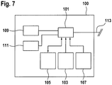
- Figure 7 schematically shows a simplified block diagram of a computer system 100 for implementing the data processing system 31 for processing acquired intensity values for x-rays penetrating the inspection object or for implementing the control unit 33. It goes without saying that the data processing system 31 and control unit 33 can also be implemented using a single computer system 100.
- the data processing system 31 for processing and evaluating the intensity values detected by the X-ray inspection system 1 can take place in the computer system 100, which is arranged locally in or on the X-ray inspection system.
- the computer system 100 for example coupled via a computer network, to be arranged at a central location in the manner of a mainframe computer system, in particular for a plurality of X-ray inspection systems.
- the computer system 100 it is also possible for the computer system 100 to be formed by a plurality of computer systems connected to one another via a computer network and thus spatially distributed.
- the computer system 100 has at least one processor 101 controllable by means of software.
- Software means for example computer programs for implementing the desired functions, are stored in at least one first memory 103 when the computer program is executed in the at least one processor 101.
- At least one second memory 105 is provided as a working memory for data to be processed and intermediate or final results.
- a third memory 107 can be provided in which comparison values for specific material size values are stored in the form of a database; this can be, for example, specific variables of known materials that influence the absorption of X-rays, in particular the density and / or the mass attenuation coefficient and / or the effective number of nuclei of these materials.
- the data processing system 100 also has input means 109, such as a keyboard, a touchpad, a pointer input unit (computer mouse) or the like, or a variant of some of these means or a combination thereof specifically tailored to simple operation.
- input means 109 such as a keyboard, a touchpad, a pointer input unit (computer mouse) or the like, or a variant of some of these means or a combination thereof specifically tailored to simple operation.
- An imaging output means 111 such as at least one screen or monitor 35 ( Figure 1 ) intended.
- the computer system 100 is coupled to the X-ray inspection system 1 via a data interface 113, i.e. depending on the function to be implemented with actuators (such as motors 4, 29, radiation sources 7, 9 etc.) or sensors (e.g. detector unit 25).
- actuators such as motors 4, 29, radiation sources 7, 9 etc.
- sensors e.g. detector unit 25.
- processor can refer to any electronic device or circuit or part of an electronic device or circuit which processes electronic data from registers and / or a memory, to convert electronic data into other electronic data or to generate corresponding output data from input data, which can be stored in registers and / or a memory.
- the computer system 100 can comprise a processor 101 or a plurality of processors.
- the computer system 100 is preferably implemented as a combination of hardware, firmware and software.
- the methods described here can be implemented partially or completely as software means stored on a machine-readable medium, which can be read into the computer system 100 and executed for implementation.
- a machine-readable medium can be configured for any mechanism for storing, transmitting, or receiving information in a form that is readable by a computer.
- Read-only memory (ROM), random access memory (RAM), magnetic storage disks, optical storage media, and flash storage media are mentioned here as non-exhaustive examples.
- the software means can also be in the form of a data stream as optical, acoustic or other signals forwarded (e.g. as carrier waves, infrared signals, digital signals, etc.) that are transmitted via appropriate interfaces, for example antennas, which transmit these signals and / or can be received, transmitted.
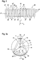
- Figure 2 shows a development of a first embodiment of the detector unit 25 in a simplified representation, that is, there are significantly fewer rows 37 and columns 39 of FIG Detector elements 27 as indicated in reality.
- the individual detector elements 27 are each indicated in a simplified manner by a rectangle.
- the xyz coordinate system is also for orientation and corresponding to Figure 1 shown.
- the columns 39 are numbered positive or negative starting from the center outwards.
- the straight line is denoted by 42 which results from a projection of the axis of rotation 5 from a point between the radiation sources 7, 9 onto the detector unit 25.
- the straight line 41 of the Figure 1 is also indicated for orientation.
- the detector unit 25 does not consist of a detector field or detector array that is geometrically completely (ie fill factor 100%) occupied by detector elements 27, but of detector columns 39 spaced from one another by gaps 28.
- the width of the gaps 28 corresponds to the distance D1 between two adjacent detector elements 27.
- the individual Detector elements 27 have a width B.
- the distance from a right edge K1 of a detector element 27 'to the right edge K2 of the immediately adjacent detector element 27 "in the same line 37 is marked with P and is referred to by the technical term pitch.
- the geometric efficiency ( engl, geometric efficiency) or the line density of the detector unit 25 is defined as the quotient B / P.
- FIG. 3 is a schematic plan view of the X-ray inspection system 1 of FIG Figure 1 in direction z, ie in the direction of the axis of rotation 5.
- the xyz coordinate system is also for orientation and corresponding to Figure 1 registered.
- the two radiation sources 7 and 9 are shown on the circumferential line of the gantry 3, which are arranged at a distance D2 from one another on a circular path running to the axis of rotation 5 with the radius R2.
- the detector unit 25 with the detector elements 27 is shown arranged on a concentric circular path with radius R1.
- the second distance D2 between the at least two independently controllable x-ray sources 7, 9 is shown in FIG Figure 3a
- the exemplary embodiment shown is set such that D 2 ⁇ B D 1, where B is the width of a detector element 27 in the circumferential direction of the gantry 3; that is to say, the width D1 of a gap 28 is at least as great as the width of a detector element 27.
- the distances, especially the distance D2 are not shown to scale for the sake of simplicity.
- n 2
- the second distance D2 of the radiation sources 7, 9 is set to approximately the distance of the width B of a detector element 27, at least every second detector line 29 can be omitted.
- the pitch P is then exactly double the width B.
- 50% or a detector line density of 50% for the geometric efficiency defined above In conventional x-ray systems of the generic type with one radiation source or several radiation sources which, however, are not spaced according to the invention, it is necessary to achieve the desired triggering of the virtual detector in the measuring field to occupy the detector unit 25 with detector elements 27 in such a way that a detector row density of approximately 100 % results.
- Such detector units are complex and expensive.
- gaps 28 are created between the individual detector gaps 39 by means of the first distance D1, the width of which is preferably set in a range from more than 100% to a maximum of 250% of the width B of a detector element 27 can be. Even at a distance D1 that is equal to the width B of a detector element 27, the effort with regard to the detector elements 27 and their wiring is halved, with essentially the same triggering in the measuring field being achieved as in systems with a focus and a detector unit with 100 % Fill factor.
- the inventors have also found that the first distance D1, i.e. the width of the gap 28 between the individual detector rows 39 can even be increased to twice the value of the width B of a detector element 27 - with still acceptable quality losses. This results in a geometric efficiency of 25% or a detector line density of 25%.
- a detector element 27 can be, for example, a scintillator pixel that receives X-rays and converts them into light pulses, which can then be converted into an electrical measurement signal via an integrated photodiode.
- the structure is complex, and the wiring of the individual detectors 27 is particularly complicated.
- FIG. 3 is a schematic plan view of the X-ray inspection system 1 of FIG Figure 1 in direction z, ie in the direction of the axis of rotation 5, which is not part of the invention, with an alternatively designed detector unit 25 ', ie a modification compared to FIG Figure 3a .
- the xyz coordinate system is also for orientation and corresponding to Figure 1 registered.
- the two radiation sources 7, 9 are shown on the circumferential line of the gantry 3, which are arranged at a distance D2 from one another on a circular path running to the axis of rotation 5 with the radius R2.
- the detector unit 25 ' Arranged opposite the radiation sources 7, 9 is the detector unit 25 'with the detector elements 27, which are arranged on a circular path with radius R1' opposite approximately a point between the radiation sources 7 and 9.
- R1' 2 R2
- ie R1 ' is approximately twice as large as R2.
- the second distance D2 is in the Figure 3b
- the embodiment shown is set between the at least two independently controllable X-ray sources 7, 9 such that D 2 ⁇ B D 1 applies, where B is the width of a detector element 27 in the circumferential direction; also at Figure 3b it should be noted that the distances, especially the distance D2, are not drawn to scale for the sake of simplicity.
- FIG 4 shows details of the detector unit of Figure 3a with detector elements arranged one above the other from the point of view of the radiation sources 7, 9, first 27a and second 27b, in order to enable a dual-energy or multi-energy evaluation. That is, each detector element 27 is set up for the detection of two energy ranges (or frequency ranges) from the X-ray spectrum of the radiation sources 7, 9, in that the first detector elements 27a are set up to detect X-rays from the first energy range and the second detector elements 27b are set up to detect X-rays are set up for a second energy range. For this purpose, a second detector element 27b is arranged below a first detector element 27a.
- the first detector elements 27a and the second detector elements 27b each supply an associated measured value, so that measured values are available for two energy ranges.
- the multi-energy evaluation can be based on this; for example in order to be able to determine not only a probable density but also the probable effective ordinal number Z eff of a material in a spatial element (voxel) of the examination area.
- a detector element 27 actually consists of two Detectors arranged one above the other, as detector elements 27, can for example be taken from the above EP 1 186 909 known detector elements are used.
- the detector unit 25 is essentially only constructed from detector columns 39 spaced apart from one another, the construction of the detector elements can be further simplified, particularly with regard to multiple energy evaluation.
- FIG. 13 shows a plan view of an exemplary alternative of the detector unit 25 of FIG Figure 4 , which is not part of the invention, with first 27a and second 27b arranged next to each other detector elements for a multi-energy evaluation.
- Figure 6 shows a schematic plan view of the gantry 3 of a further development of the X-ray inspection system of FIG Figure 1 with the direction of view along the axis of rotation 5 with the further developed detector unit 25 of FIG Figure 5 . Also in the example of Figures 5 and 6 a gap 28 is provided between adjacent detector elements 27a, 27b.
- the Figures 5 and 6 the actual distance between two first detector elements 27a or two second detector elements 27b is enlarged to twice the width B of one of the detector elements 27a, 27b; that is, D 1 / B ⁇ 200% applies to the ratio. This reduces the resolution of the information about the inspection object detected with the first or second detector elements.
- the first detector elements 27a and second detector elements 27b are in the Figures 5 and 6 not like in the execution of the Figure 4 one above the other, but arranged side by side. This additionally simplifies the construction of the detector unit 25, in particular the wiring of the individual detector elements 27 does not cause any impairment more, since none of the detector elements 27 lies in the beam path of another detector element in the case of a multiple energy evaluation.
- the first distance D1 of the individual first 39a and second 39b detector columns is here also set to more than the width B of a detector element 27a, 27b ( ie D 1 / B 100%).
- each detector element 27a, 27b has at least one gap 28 available, which can be used, for example, for a simplified wiring of the detector element 27a or 27b.
- the radius of curvature of the detector units 25 of the Figures 4 and 6th in the circumferential direction, as in the Figure 3b shown, be designed according to a circular path with the radius R1 'around the center of the foci.
- the space requirement for the detector unit increases, but all of the individual detector elements 27 can be equally better aligned with the radiation sources 7, 9 or 6, 7, 8, 9.
Landscapes
- Health & Medical Sciences (AREA)
- Physics & Mathematics (AREA)
- Life Sciences & Earth Sciences (AREA)
- General Physics & Mathematics (AREA)
- Spectroscopy & Molecular Physics (AREA)
- Molecular Biology (AREA)
- High Energy & Nuclear Physics (AREA)
- Toxicology (AREA)
- Chemical & Material Sciences (AREA)
- Analytical Chemistry (AREA)
- Biochemistry (AREA)
- General Health & Medical Sciences (AREA)
- Immunology (AREA)
- Pathology (AREA)
- Analysing Materials By The Use Of Radiation (AREA)
Applications Claiming Priority (2)
| Application Number | Priority Date | Filing Date | Title |
|---|---|---|---|
| DE102013104193.0A DE102013104193A1 (de) | 2013-04-25 | 2013-04-25 | CT-Röntgenprüfanlage, insbesondere zur Inspektion von Objekten |
| PCT/EP2014/058458 WO2014174077A1 (de) | 2013-04-25 | 2014-04-25 | Ct-röntgenprüfanlage, insbesondere zur inspektion von objekten |
Publications (2)
| Publication Number | Publication Date |
|---|---|
| EP2989451A1 EP2989451A1 (de) | 2016-03-02 |
| EP2989451B1 true EP2989451B1 (de) | 2021-12-22 |
Family
ID=50628804
Family Applications (1)
| Application Number | Title | Priority Date | Filing Date |
|---|---|---|---|
| EP14720571.0A Active EP2989451B1 (de) | 2013-04-25 | 2014-04-25 | Ct-röntgenprüfanlage, insbesondere zur inspektion von objekten |
Country Status (4)
| Country | Link |
|---|---|
| EP (1) | EP2989451B1 (pl) |
| DE (1) | DE102013104193A1 (pl) |
| PL (1) | PL2989451T3 (pl) |
| WO (1) | WO2014174077A1 (pl) |
Families Citing this family (4)
| Publication number | Priority date | Publication date | Assignee | Title |
|---|---|---|---|---|
| DE102017202085A1 (de) | 2017-02-09 | 2018-08-09 | Tom Hanrath | Fördervorrichtung zur Versorgung einer Garnbearbeitungsmaschine, insbesondere einer Spinnstrickmaschine sowie Produktionseinrichtung umfassend eine solche und Verfahren zur Versorgung einer Garnbearbeitungsmaschine verwendend eine solche |
| US10893839B2 (en) * | 2018-06-06 | 2021-01-19 | General Electric Company | Computed tomography system and method configured to image at different energy levels and focal spot positions |
| CN211741602U (zh) * | 2020-01-17 | 2020-10-23 | 德瑞科(天津)机械制造有限公司 | 一种安检机 |
| CN114113158A (zh) * | 2021-11-08 | 2022-03-01 | 上海物影科技有限公司 | 目标物体识别装置及系统 |
Citations (2)
| Publication number | Priority date | Publication date | Assignee | Title |
|---|---|---|---|---|
| US5841832A (en) * | 1991-02-13 | 1998-11-24 | Lunar Corporation | Dual-energy x-ray detector providing spatial and temporal interpolation |
| WO2006114716A2 (en) * | 2005-04-26 | 2006-11-02 | Koninklijke Philips Electronics, N.V. | Double decker detector for spectral ct |
Family Cites Families (12)
| Publication number | Priority date | Publication date | Assignee | Title |
|---|---|---|---|---|
| NL8600067A (nl) * | 1986-01-15 | 1987-08-03 | Philips Nv | Roentgenscanner met dual energy beeldvorming. |
| US5361291A (en) * | 1991-11-20 | 1994-11-01 | General Electric Company | Deconvolution filter for CT system |
| DE10044357A1 (de) | 2000-09-07 | 2002-03-21 | Heimann Systems Gmbh & Co | Detektoranordnung zur Detektion von Röntgenstrahlen |
| DE10149254B4 (de) | 2001-10-05 | 2006-04-20 | Smiths Heimann Gmbh | Verfahren und Vorrichtung zur Detektion eines bestimmten Materials in einem Objekt mittels elektromagnetischer Strahlen |
| US7779383B2 (en) * | 2005-12-01 | 2010-08-17 | Sap Ag | Composition model and composition validation algorithm for ubiquitous computing applications |
| CN101326437A (zh) | 2005-12-12 | 2008-12-17 | 显示成像技术有限公司 | 移置光线型ct检查 |
| US7372934B2 (en) * | 2005-12-22 | 2008-05-13 | General Electric Company | Method for performing image reconstruction using hybrid computed tomography detectors |
| CN101410727A (zh) | 2006-03-29 | 2009-04-15 | 皇家飞利浦电子股份有限公司 | 高效的双能x射线衰减测量 |
| WO2012112153A1 (en) * | 2011-02-17 | 2012-08-23 | Analogic Corporation | Detector array having effective size larger than actual size |
| US20120236987A1 (en) * | 2011-03-18 | 2012-09-20 | David Ruimi | Multiple energy ct scanner |
| US20130016805A1 (en) * | 2011-07-15 | 2013-01-17 | Toshiba Medical Systems Corporation | Method and system for acquiring sparse channel data and for image processing utilizing iterative reconstruction algorithms |
| US9069092B2 (en) * | 2012-02-22 | 2015-06-30 | L-3 Communication Security and Detection Systems Corp. | X-ray imager with sparse detector array |
-
2013
- 2013-04-25 DE DE102013104193.0A patent/DE102013104193A1/de not_active Ceased
-
2014
- 2014-04-25 WO PCT/EP2014/058458 patent/WO2014174077A1/de not_active Ceased
- 2014-04-25 PL PL14720571.0T patent/PL2989451T3/pl unknown
- 2014-04-25 EP EP14720571.0A patent/EP2989451B1/de active Active
Patent Citations (2)
| Publication number | Priority date | Publication date | Assignee | Title |
|---|---|---|---|---|
| US5841832A (en) * | 1991-02-13 | 1998-11-24 | Lunar Corporation | Dual-energy x-ray detector providing spatial and temporal interpolation |
| WO2006114716A2 (en) * | 2005-04-26 | 2006-11-02 | Koninklijke Philips Electronics, N.V. | Double decker detector for spectral ct |
Also Published As
| Publication number | Publication date |
|---|---|
| EP2989451A1 (de) | 2016-03-02 |
| DE102013104193A1 (de) | 2014-10-30 |
| PL2989451T3 (pl) | 2022-10-10 |
| WO2014174077A1 (de) | 2014-10-30 |
Similar Documents
| Publication | Publication Date | Title |
|---|---|---|
| DE102009061736B3 (de) | Abbildungssystem mit Linearabtastung und Verfahren hierfür | |
| DE112012004856B4 (de) | Kontrollsystem und Verfahren zur schnellen, platzsparenden Röntgentomografiekontrolle | |
| EP1434984B1 (de) | Direkte und indirekte Bestimmung des Volumens von Sprengstoff in einem Behälter mittels Röntgentransmission in verschiedenen Untersuchungsebenen | |
| DE69629707T2 (de) | Ortung von schmuggelware durch verwendung von interaktiver multisonden-tomographie | |
| EP3094995B1 (de) | Verfahren und röntgenprüfanlage, insbesondere zur zerstörungsfreien inspektion von objekten | |
| RU2305829C1 (ru) | Способ и устройство для распознавания материалов с помощью быстрых нейтронов и непрерывного спектрального рентгеновского излучения | |
| DE69629906T2 (de) | Nachweis von sprengstoffen und anderer schmuggelware unter verwendung transmittierter und gestreuter röntgenstrahlung | |
| DE69624685T2 (de) | Einrichtung zur roentgenstrahlenuntersuchung | |
| DE102007020545A1 (de) | Detektormatrix und Vorrichtung zu deren Verwendung | |
| DE112008001662T5 (de) | Verfahren und System zur Detektion von Schmuggelgut unter Verwendung von Photoneutronen und Röntgenstrahlen | |
| EP1215482A2 (de) | Vorrichtung zur Durchleuchtung von Objekten | |
| DE102011056349A1 (de) | Gestapelte Flat-Panel-Röntgendetektoranordnung und Verfahren zur Herstellung derselben | |
| HK1218163A1 (zh) | 探测器装置、双能ct系统和使用该系统的检测方法 | |
| DE102011056348A1 (de) | Gestapelte Röntgendetektoranordnung und Verfahren zu ihrer Herstellung | |
| DE102006054573A1 (de) | Abbildungssystem | |
| EP2265938A1 (de) | Verfahren und vorrichtung zur detektion eines bestimmten materials in einem objekt mittels elektromagnetischer strahlen | |
| DE202013011333U1 (de) | Gerüstlose CT-Vorrichtung | |
| DE102008043210B4 (de) | Prüfsystem mit einem CT-Gerät und einer zusätzlichen Scan-Abbildungsvorrichtung | |
| EP2989451B1 (de) | Ct-röntgenprüfanlage, insbesondere zur inspektion von objekten | |
| EP1672358B1 (de) | Anordnung zum Messen des Impulsübertragungsspektrums von elastisch gestreuten Röntgenquanten sowie Verfahren zur Bestimmung dieses Impulsübertragungsspektrums | |
| DE102007052448A1 (de) | Korrektur der Querstreuung in einem Mehrstrahler-CT-Gerät | |
| EP3052966B1 (de) | Röntgendetektor | |
| DE102007045798A1 (de) | Anordnung zur Aufnahme von Röntgenstrahlen- und/oder Gammastrahlen-Streuungsbildern | |
| EP0959344A1 (de) | Verfahren und Baugruppe zur Durchführung von Durchstrahlungsprüfungen an Werkstoffeinheiten | |
| WO1997033160A1 (de) | Verfahren und vorrichtung zur automatischen radioskopischen qualitätskontrolle von nahrungsmitteln |
Legal Events
| Date | Code | Title | Description |
|---|---|---|---|
| PUAI | Public reference made under article 153(3) epc to a published international application that has entered the european phase |
Free format text: ORIGINAL CODE: 0009012 |
|
| 17P | Request for examination filed |
Effective date: 20151119 |
|
| AK | Designated contracting states |
Kind code of ref document: A1 Designated state(s): AL AT BE BG CH CY CZ DE DK EE ES FI FR GB GR HR HU IE IS IT LI LT LU LV MC MK MT NL NO PL PT RO RS SE SI SK SM TR |
|
| AX | Request for extension of the european patent |
Extension state: BA ME |
|
| DAX | Request for extension of the european patent (deleted) | ||
| STAA | Information on the status of an ep patent application or granted ep patent |
Free format text: STATUS: EXAMINATION IS IN PROGRESS |
|
| 17Q | First examination report despatched |
Effective date: 20170710 |
|
| GRAP | Despatch of communication of intention to grant a patent |
Free format text: ORIGINAL CODE: EPIDOSNIGR1 |
|
| STAA | Information on the status of an ep patent application or granted ep patent |
Free format text: STATUS: GRANT OF PATENT IS INTENDED |
|
| INTG | Intention to grant announced |
Effective date: 20210707 |
|
| GRAS | Grant fee paid |
Free format text: ORIGINAL CODE: EPIDOSNIGR3 |
|
| GRAA | (expected) grant |
Free format text: ORIGINAL CODE: 0009210 |
|
| STAA | Information on the status of an ep patent application or granted ep patent |
Free format text: STATUS: THE PATENT HAS BEEN GRANTED |
|
| AK | Designated contracting states |
Kind code of ref document: B1 Designated state(s): AL AT BE BG CH CY CZ DE DK EE ES FI FR GB GR HR HU IE IS IT LI LT LU LV MC MK MT NL NO PL PT RO RS SE SI SK SM TR |
|
| REG | Reference to a national code |
Ref country code: GB Ref legal event code: FG4D Free format text: NOT ENGLISH |
|
| REG | Reference to a national code |
Ref country code: CH Ref legal event code: EP |
|
| REG | Reference to a national code |
Ref country code: DE Ref legal event code: R096 Ref document number: 502014016043 Country of ref document: DE |
|
| REG | Reference to a national code |
Ref country code: AT Ref legal event code: REF Ref document number: 1457385 Country of ref document: AT Kind code of ref document: T Effective date: 20220115 |
|
| REG | Reference to a national code |
Ref country code: IE Ref legal event code: FG4D Free format text: LANGUAGE OF EP DOCUMENT: GERMAN |
|
| REG | Reference to a national code |
Ref country code: DE Ref legal event code: R081 Ref document number: 502014016043 Country of ref document: DE Owner name: SMITHS DETECTION GERMANY GMBH, DE Free format text: FORMER OWNER: SMITHS HEIMANN GMBH, 65205 WIESBADEN, DE |
|
| REG | Reference to a national code |
Ref country code: NL Ref legal event code: FP |
|
| REG | Reference to a national code |
Ref country code: LT Ref legal event code: MG9D |
|
| RAP4 | Party data changed (patent owner data changed or rights of a patent transferred) |
Owner name: SMITHS DETECTION GERMANY GMBH |
|
| REG | Reference to a national code |
Ref country code: NL Ref legal event code: HC Owner name: SMITHS DETECTION GERMANY GMBH; DE Free format text: DETAILS ASSIGNMENT: CHANGE OF OWNER(S), CHANGE OF OWNER(S) NAME; FORMER OWNER NAME: SMITHS HEIMANN GMBH Effective date: 20220315 |
|
| PG25 | Lapsed in a contracting state [announced via postgrant information from national office to epo] |
Ref country code: RS Free format text: LAPSE BECAUSE OF FAILURE TO SUBMIT A TRANSLATION OF THE DESCRIPTION OR TO PAY THE FEE WITHIN THE PRESCRIBED TIME-LIMIT Effective date: 20211222 Ref country code: LT Free format text: LAPSE BECAUSE OF FAILURE TO SUBMIT A TRANSLATION OF THE DESCRIPTION OR TO PAY THE FEE WITHIN THE PRESCRIBED TIME-LIMIT Effective date: 20211222 Ref country code: FI Free format text: LAPSE BECAUSE OF FAILURE TO SUBMIT A TRANSLATION OF THE DESCRIPTION OR TO PAY THE FEE WITHIN THE PRESCRIBED TIME-LIMIT Effective date: 20211222 Ref country code: BG Free format text: LAPSE BECAUSE OF FAILURE TO SUBMIT A TRANSLATION OF THE DESCRIPTION OR TO PAY THE FEE WITHIN THE PRESCRIBED TIME-LIMIT Effective date: 20220322 |
|
| PG25 | Lapsed in a contracting state [announced via postgrant information from national office to epo] |
Ref country code: SE Free format text: LAPSE BECAUSE OF FAILURE TO SUBMIT A TRANSLATION OF THE DESCRIPTION OR TO PAY THE FEE WITHIN THE PRESCRIBED TIME-LIMIT Effective date: 20211222 Ref country code: NO Free format text: LAPSE BECAUSE OF FAILURE TO SUBMIT A TRANSLATION OF THE DESCRIPTION OR TO PAY THE FEE WITHIN THE PRESCRIBED TIME-LIMIT Effective date: 20220322 Ref country code: LV Free format text: LAPSE BECAUSE OF FAILURE TO SUBMIT A TRANSLATION OF THE DESCRIPTION OR TO PAY THE FEE WITHIN THE PRESCRIBED TIME-LIMIT Effective date: 20211222 Ref country code: HR Free format text: LAPSE BECAUSE OF FAILURE TO SUBMIT A TRANSLATION OF THE DESCRIPTION OR TO PAY THE FEE WITHIN THE PRESCRIBED TIME-LIMIT Effective date: 20211222 Ref country code: GR Free format text: LAPSE BECAUSE OF FAILURE TO SUBMIT A TRANSLATION OF THE DESCRIPTION OR TO PAY THE FEE WITHIN THE PRESCRIBED TIME-LIMIT Effective date: 20220323 |
|
| PG25 | Lapsed in a contracting state [announced via postgrant information from national office to epo] |
Ref country code: SM Free format text: LAPSE BECAUSE OF FAILURE TO SUBMIT A TRANSLATION OF THE DESCRIPTION OR TO PAY THE FEE WITHIN THE PRESCRIBED TIME-LIMIT Effective date: 20211222 Ref country code: SK Free format text: LAPSE BECAUSE OF FAILURE TO SUBMIT A TRANSLATION OF THE DESCRIPTION OR TO PAY THE FEE WITHIN THE PRESCRIBED TIME-LIMIT Effective date: 20211222 Ref country code: RO Free format text: LAPSE BECAUSE OF FAILURE TO SUBMIT A TRANSLATION OF THE DESCRIPTION OR TO PAY THE FEE WITHIN THE PRESCRIBED TIME-LIMIT Effective date: 20211222 Ref country code: PT Free format text: LAPSE BECAUSE OF FAILURE TO SUBMIT A TRANSLATION OF THE DESCRIPTION OR TO PAY THE FEE WITHIN THE PRESCRIBED TIME-LIMIT Effective date: 20220422 Ref country code: ES Free format text: LAPSE BECAUSE OF FAILURE TO SUBMIT A TRANSLATION OF THE DESCRIPTION OR TO PAY THE FEE WITHIN THE PRESCRIBED TIME-LIMIT Effective date: 20211222 Ref country code: EE Free format text: LAPSE BECAUSE OF FAILURE TO SUBMIT A TRANSLATION OF THE DESCRIPTION OR TO PAY THE FEE WITHIN THE PRESCRIBED TIME-LIMIT Effective date: 20211222 Ref country code: CZ Free format text: LAPSE BECAUSE OF FAILURE TO SUBMIT A TRANSLATION OF THE DESCRIPTION OR TO PAY THE FEE WITHIN THE PRESCRIBED TIME-LIMIT Effective date: 20211222 |
|
| REG | Reference to a national code |
Ref country code: DE Ref legal event code: R097 Ref document number: 502014016043 Country of ref document: DE |
|
| PG25 | Lapsed in a contracting state [announced via postgrant information from national office to epo] |
Ref country code: IS Free format text: LAPSE BECAUSE OF FAILURE TO SUBMIT A TRANSLATION OF THE DESCRIPTION OR TO PAY THE FEE WITHIN THE PRESCRIBED TIME-LIMIT Effective date: 20220422 |
|
| PLBE | No opposition filed within time limit |
Free format text: ORIGINAL CODE: 0009261 |
|
| STAA | Information on the status of an ep patent application or granted ep patent |
Free format text: STATUS: NO OPPOSITION FILED WITHIN TIME LIMIT |
|
| PG25 | Lapsed in a contracting state [announced via postgrant information from national office to epo] |
Ref country code: DK Free format text: LAPSE BECAUSE OF FAILURE TO SUBMIT A TRANSLATION OF THE DESCRIPTION OR TO PAY THE FEE WITHIN THE PRESCRIBED TIME-LIMIT Effective date: 20211222 Ref country code: AL Free format text: LAPSE BECAUSE OF FAILURE TO SUBMIT A TRANSLATION OF THE DESCRIPTION OR TO PAY THE FEE WITHIN THE PRESCRIBED TIME-LIMIT Effective date: 20211222 |
|
| 26N | No opposition filed |
Effective date: 20220923 |
|
| REG | Reference to a national code |
Ref country code: CH Ref legal event code: PL |
|
| REG | Reference to a national code |
Ref country code: BE Ref legal event code: MM Effective date: 20220430 |
|
| PG25 | Lapsed in a contracting state [announced via postgrant information from national office to epo] |
Ref country code: MC Free format text: LAPSE BECAUSE OF FAILURE TO SUBMIT A TRANSLATION OF THE DESCRIPTION OR TO PAY THE FEE WITHIN THE PRESCRIBED TIME-LIMIT Effective date: 20211222 Ref country code: LU Free format text: LAPSE BECAUSE OF NON-PAYMENT OF DUE FEES Effective date: 20220425 Ref country code: LI Free format text: LAPSE BECAUSE OF NON-PAYMENT OF DUE FEES Effective date: 20220430 Ref country code: CH Free format text: LAPSE BECAUSE OF NON-PAYMENT OF DUE FEES Effective date: 20220430 |
|
| PG25 | Lapsed in a contracting state [announced via postgrant information from national office to epo] |
Ref country code: SI Free format text: LAPSE BECAUSE OF FAILURE TO SUBMIT A TRANSLATION OF THE DESCRIPTION OR TO PAY THE FEE WITHIN THE PRESCRIBED TIME-LIMIT Effective date: 20211222 Ref country code: BE Free format text: LAPSE BECAUSE OF NON-PAYMENT OF DUE FEES Effective date: 20220430 |
|
| PG25 | Lapsed in a contracting state [announced via postgrant information from national office to epo] |
Ref country code: IE Free format text: LAPSE BECAUSE OF NON-PAYMENT OF DUE FEES Effective date: 20220425 |
|
| REG | Reference to a national code |
Ref country code: AT Ref legal event code: MM01 Ref document number: 1457385 Country of ref document: AT Kind code of ref document: T Effective date: 20220425 |
|
| P01 | Opt-out of the competence of the unified patent court (upc) registered |
Effective date: 20230528 |
|
| PG25 | Lapsed in a contracting state [announced via postgrant information from national office to epo] |
Ref country code: AT Free format text: LAPSE BECAUSE OF NON-PAYMENT OF DUE FEES Effective date: 20220425 |
|
| PG25 | Lapsed in a contracting state [announced via postgrant information from national office to epo] |
Ref country code: HU Free format text: LAPSE BECAUSE OF FAILURE TO SUBMIT A TRANSLATION OF THE DESCRIPTION OR TO PAY THE FEE WITHIN THE PRESCRIBED TIME-LIMIT; INVALID AB INITIO Effective date: 20140425 |
|
| PG25 | Lapsed in a contracting state [announced via postgrant information from national office to epo] |
Ref country code: MK Free format text: LAPSE BECAUSE OF FAILURE TO SUBMIT A TRANSLATION OF THE DESCRIPTION OR TO PAY THE FEE WITHIN THE PRESCRIBED TIME-LIMIT Effective date: 20211222 Ref country code: CY Free format text: LAPSE BECAUSE OF FAILURE TO SUBMIT A TRANSLATION OF THE DESCRIPTION OR TO PAY THE FEE WITHIN THE PRESCRIBED TIME-LIMIT Effective date: 20211222 |
|
| PG25 | Lapsed in a contracting state [announced via postgrant information from national office to epo] |
Ref country code: TR Free format text: LAPSE BECAUSE OF FAILURE TO SUBMIT A TRANSLATION OF THE DESCRIPTION OR TO PAY THE FEE WITHIN THE PRESCRIBED TIME-LIMIT Effective date: 20211222 |
|
| PG25 | Lapsed in a contracting state [announced via postgrant information from national office to epo] |
Ref country code: MT Free format text: LAPSE BECAUSE OF FAILURE TO SUBMIT A TRANSLATION OF THE DESCRIPTION OR TO PAY THE FEE WITHIN THE PRESCRIBED TIME-LIMIT Effective date: 20211222 |
|
| PGFP | Annual fee paid to national office [announced via postgrant information from national office to epo] |
Ref country code: NL Payment date: 20250317 Year of fee payment: 12 |
|
| PGFP | Annual fee paid to national office [announced via postgrant information from national office to epo] |
Ref country code: FR Payment date: 20250310 Year of fee payment: 12 Ref country code: PL Payment date: 20250314 Year of fee payment: 12 |
|
| PGFP | Annual fee paid to national office [announced via postgrant information from national office to epo] |
Ref country code: IT Payment date: 20250320 Year of fee payment: 12 Ref country code: GB Payment date: 20250306 Year of fee payment: 12 |
|
| PGFP | Annual fee paid to national office [announced via postgrant information from national office to epo] |
Ref country code: DE Payment date: 20250305 Year of fee payment: 12 |