EP2989451B1 - X-ray ct inspection system, in particular for inspecting objects - Google Patents
X-ray ct inspection system, in particular for inspecting objects Download PDFInfo
- Publication number
- EP2989451B1 EP2989451B1 EP14720571.0A EP14720571A EP2989451B1 EP 2989451 B1 EP2989451 B1 EP 2989451B1 EP 14720571 A EP14720571 A EP 14720571A EP 2989451 B1 EP2989451 B1 EP 2989451B1
- Authority
- EP
- European Patent Office
- Prior art keywords
- detector
- ray
- detector elements
- rotation
- inspection
- Prior art date
- Legal status (The legal status is an assumption and is not a legal conclusion. Google has not performed a legal analysis and makes no representation as to the accuracy of the status listed.)
- Active
Links
- 238000007689 inspection Methods 0.000 title claims description 99
- 230000005855 radiation Effects 0.000 claims description 64
- 238000000034 method Methods 0.000 claims description 9
- 230000001066 destructive effect Effects 0.000 claims description 6
- 230000000149 penetrating effect Effects 0.000 claims description 6
- 230000003213 activating effect Effects 0.000 claims 1
- 230000001678 irradiating effect Effects 0.000 claims 1
- 238000001514 detection method Methods 0.000 description 24
- 238000011156 evaluation Methods 0.000 description 16
- 238000012545 processing Methods 0.000 description 13
- 239000000463 material Substances 0.000 description 8
- 230000015654 memory Effects 0.000 description 6
- 230000006870 function Effects 0.000 description 5
- 238000011161 development Methods 0.000 description 4
- 230000018109 developmental process Effects 0.000 description 4
- 239000000383 hazardous chemical Substances 0.000 description 4
- 238000005259 measurement Methods 0.000 description 4
- 238000010276 construction Methods 0.000 description 3
- 230000007547 defect Effects 0.000 description 3
- 230000002950 deficient Effects 0.000 description 3
- 238000012986 modification Methods 0.000 description 3
- 230000004048 modification Effects 0.000 description 3
- 230000008569 process Effects 0.000 description 3
- 230000009467 reduction Effects 0.000 description 3
- 230000003595 spectral effect Effects 0.000 description 3
- 239000000126 substance Substances 0.000 description 3
- 238000012360 testing method Methods 0.000 description 3
- 238000002591 computed tomography Methods 0.000 description 2
- 238000004590 computer program Methods 0.000 description 2
- 238000002247 constant time method Methods 0.000 description 2
- 238000001816 cooling Methods 0.000 description 2
- 238000013461 design Methods 0.000 description 2
- 238000010586 diagram Methods 0.000 description 2
- 239000002360 explosive Substances 0.000 description 2
- 238000004519 manufacturing process Methods 0.000 description 2
- 230000003287 optical effect Effects 0.000 description 2
- 230000035945 sensitivity Effects 0.000 description 2
- 238000002083 X-ray spectrum Methods 0.000 description 1
- 238000010521 absorption reaction Methods 0.000 description 1
- 230000004913 activation Effects 0.000 description 1
- 238000003491 array Methods 0.000 description 1
- 238000004891 communication Methods 0.000 description 1
- 230000006735 deficit Effects 0.000 description 1
- 239000003814 drug Substances 0.000 description 1
- 229940079593 drug Drugs 0.000 description 1
- 230000000694 effects Effects 0.000 description 1
- 239000011521 glass Substances 0.000 description 1
- 238000003384 imaging method Methods 0.000 description 1
- 238000009434 installation Methods 0.000 description 1
- 230000007246 mechanism Effects 0.000 description 1
- 238000004377 microelectronic Methods 0.000 description 1
- 238000012856 packing Methods 0.000 description 1
- 230000035515 penetration Effects 0.000 description 1
- 230000002093 peripheral effect Effects 0.000 description 1
- 238000000275 quality assurance Methods 0.000 description 1
- 238000003908 quality control method Methods 0.000 description 1
- 238000005476 soldering Methods 0.000 description 1
- 230000007847 structural defect Effects 0.000 description 1
- 230000002123 temporal effect Effects 0.000 description 1
- 238000004154 testing of material Methods 0.000 description 1
- 230000003936 working memory Effects 0.000 description 1
Images


Classifications
-
- G—PHYSICS
- G01—MEASURING; TESTING
- G01N—INVESTIGATING OR ANALYSING MATERIALS BY DETERMINING THEIR CHEMICAL OR PHYSICAL PROPERTIES
- G01N23/00—Investigating or analysing materials by the use of wave or particle radiation, e.g. X-rays or neutrons, not covered by groups G01N3/00 – G01N17/00, G01N21/00 or G01N22/00
- G01N23/02—Investigating or analysing materials by the use of wave or particle radiation, e.g. X-rays or neutrons, not covered by groups G01N3/00 – G01N17/00, G01N21/00 or G01N22/00 by transmitting the radiation through the material
- G01N23/06—Investigating or analysing materials by the use of wave or particle radiation, e.g. X-rays or neutrons, not covered by groups G01N3/00 – G01N17/00, G01N21/00 or G01N22/00 by transmitting the radiation through the material and measuring the absorption
- G01N23/083—Investigating or analysing materials by the use of wave or particle radiation, e.g. X-rays or neutrons, not covered by groups G01N3/00 – G01N17/00, G01N21/00 or G01N22/00 by transmitting the radiation through the material and measuring the absorption the radiation being X-rays
-
- G—PHYSICS
- G01—MEASURING; TESTING
- G01T—MEASUREMENT OF NUCLEAR OR X-RADIATION
- G01T1/00—Measuring X-radiation, gamma radiation, corpuscular radiation, or cosmic radiation
- G01T1/29—Measurement performed on radiation beams, e.g. position or section of the beam; Measurement of spatial distribution of radiation
- G01T1/2914—Measurement of spatial distribution of radiation
- G01T1/2985—In depth localisation, e.g. using positron emitters; Tomographic imaging (longitudinal and transverse section imaging; apparatus for radiation diagnosis sequentially in different planes, steroscopic radiation diagnosis)
-
- A—HUMAN NECESSITIES
- A61—MEDICAL OR VETERINARY SCIENCE; HYGIENE
- A61B—DIAGNOSIS; SURGERY; IDENTIFICATION
- A61B6/00—Apparatus for radiation diagnosis, e.g. combined with radiation therapy equipment
- A61B6/02—Devices for diagnosis sequentially in different planes; Stereoscopic radiation diagnosis
- A61B6/03—Computerised tomographs
- A61B6/032—Transmission computed tomography [CT]
-
- A—HUMAN NECESSITIES
- A61—MEDICAL OR VETERINARY SCIENCE; HYGIENE
- A61B—DIAGNOSIS; SURGERY; IDENTIFICATION
- A61B6/00—Apparatus for radiation diagnosis, e.g. combined with radiation therapy equipment
- A61B6/40—Apparatus for radiation diagnosis, e.g. combined with radiation therapy equipment with arrangements for generating radiation specially adapted for radiation diagnosis
- A61B6/4007—Apparatus for radiation diagnosis, e.g. combined with radiation therapy equipment with arrangements for generating radiation specially adapted for radiation diagnosis characterised by using a plurality of source units
-
- A—HUMAN NECESSITIES
- A61—MEDICAL OR VETERINARY SCIENCE; HYGIENE
- A61B—DIAGNOSIS; SURGERY; IDENTIFICATION
- A61B6/00—Apparatus for radiation diagnosis, e.g. combined with radiation therapy equipment
- A61B6/48—Diagnostic techniques
- A61B6/482—Diagnostic techniques involving multiple energy imaging
Definitions
- the invention relates generally to an X-ray inspection system.
- the invention relates in particular to an X-ray inspection system for the non-destructive inspection of objects.
- DE 101 49 254 A1 shows an X-ray inspection system with several fixed radiation planes for the inspection of objects, for example for the security check of luggage at airports.
- the inspection object is conveyed through several radiation levels, each of which is emitted by a stationary radiation source.
- the intensities of the unabsorbed rays are measured and evaluated by the detector arrangements assigned to the radiation sources.
- US 7 362 847 B2 shows an X-ray inspection system of the type of a computer tomograph (CT) with a rotating gantry which is also used for object inspection.
- CT computer tomograph
- U.S. 5,361,291 A also shows a CT device in which the focal point of the X-ray tube can be moved translationally in order to double the spatial scanning rate compared to a conventional CT device in order to reduce aliasing in the reconstructed X-ray images.
- EP 0 231 037 A1 shows an X-ray scanner with an arrangement of detectors and an X-ray tube with an elongated anode or double focus.
- the X-ray scanner can be operated in different modes, with all detector signals being evaluated separately in an unpaired mode, signals from two adjacent detectors being evaluated in combination in a paired mode, and different spectral filters being assigned to adjacent detectors in a dual-energy mode.
- US 7 778 383 B2 shows a similar CT system for measuring dual-energy X-ray attenuation data of an object with an X-ray source with two different focal points and a detection device with a plurality of first and second detector elements alternating in the circumferential direction, with adjacent elements each having different spectral sensitivities.
- the object is first irradiated by X-rays from the first focal point in order to acquire first attenuation data with the first detector elements and the second detector elements. Then the object of X-rays of the second Radiated through the focus point in order to detect second attenuation data with the first and second detector elements.
- the two focal points are spatially separated from each other in such a way that a first beam path from the first focal point penetrates a certain voxel within the object and hits a first detector element and a second beam path from the second focal point penetrates the same voxel and hits an adjacent second detector element.
- X-ray inspection systems for the inspection of objects, especially for the detection of hazardous substances, are constantly advancing with regard to an increase in baggage throughput with, of course, the same high detection rate, i.e. detection reliability.
- X-ray inspection systems of the computed tomography (CT) type are very complex devices.
- the detector units required in CT devices particularly in the case of CTs with dual-energy functionality, are very expensive and, due to the high packing density of detector elements required for the desired resolutions, are complicated and therefore expensive.
- Fig. 10 shows CT methods and a CT system for measuring dual-energy X-ray attenuation data of an inspection object.
- the CT system comprises a rotatable holder, an X-ray source with two different X-ray focus points and an X-ray detection device with a plurality of first and second detector elements of different spectral sensitivity, which are arranged alternately in the direction of rotation of the holder without gaps.
- the following steps are carried out in the operation of the CT system or the execution of the method.
- the first and second focal points are spatially separated from one another in such a way that a first beam path starting from the first focal point passes through a specific voxel within the object and hits a first detector element, while a second beam path starting from the second focal point penetrates and onto the same voxel hits a second detector element.
- WO 2012/112153 A1 shows a CT method and systems with a detector array that has an effective size that is larger than the actual size of the Detector elements of the detector arrangement.
- a so-called sparse array is proposed, in which one or more channels of the detector array are omitted so that there are gaps between the detector elements in the direction of rotation of the detector arrangement.
- Similar to the WO 2012/112153 A1 show WO 2012/112153 A1 and WO 2013/126649 A2 also detector arrangement with sparse arrays.
- U.S. 5,841,832 A and WO 2006/114716 A2 show dual-energy X-ray devices which have so-called dual-energy X-ray detectors in which two types of detector elements, each designed for the detection of high or low energy X-rays, are arranged next to or one above the other.
- a core idea of the invention lies in the knowledge that in an X-ray inspection system with a rotating radiation source and with (i) a detector unit arranged opposite to rotate with it or with (ii) an annular detector unit arranged in a stationary manner around the circular path described by the rotating radiation source, by increasing the number the radiation sources, for example the X-ray focal points (foci), to reduce the number of detector elements required in the circumferential direction of the rotation.
- the fill factor (ratio of the sensitive area to the total area) of the detector unit and / or the detector elements can be reduced compared to the known X-ray inspection systems. For example, increasing the number of radiation sources from one to two, ie doubling, at least halving the number of detector elements required on the detector unit in the direction of rotation.
- the inventors first recognized that if the distance (in the direction of rotation) between the at least two radiation sources is set in the order of magnitude of the width of a detector element, the distance between the detector elements in the circumferential direction of the rotation increases to at least the width of a detector element without affecting the resolution can be. In other words, every second detector element can be eliminated.
- the structure of the detector elements or the detector unit can advantageously be simplified due to the space freed up in the detector unit.
- a gap with the width of a detector element is then located between two adjacent detector elements. This gap is also available, for example, for wiring the detector elements.
- the simplified X-ray inspection system enables X-ray recordings to be made which have the same quality, in particular the same resolution, as X-ray recordings made with a comparable X-ray inspection system with only one radiation source and the usual high number of detector elements that are arranged on the detector unit without any gaps in the circumferential direction , were made.
- the inventors have further recognized that if the distance between the at least two radiation sources is set in the order of magnitude of the width of a detector element, the distance between the detector elements in the circumferential direction of the rotation is up to twice, possibly up to 2.5 times Width of a detector element can be increased. However, this enlargement of the gaps then results in a reduction in the quality of the X-ray images. This means that the gap width can be adjusted accordingly to the specified extent with regard to a required quality, in particular resolution, of the x-ray images. As a result, even more than half of the detector elements of a detector unit with a 100% fill factor can be saved. That is to say, with the additional expenditure for the second or further x-ray sources or foci, a corresponding reduction in the expenditure for the detector unit can be achieved in addition to additional advantages. An X-ray inspection system according to the invention is therefore more cost-effective.
- An X-ray inspection system for the non-destructive inspection of objects can thus have: at least two X-ray sources (also known as foci or focal spots) rotatable about an axis of rotation in a plane of rotation for generating a beam of rays passing through an examination area and a detector unit with detector elements arranged opposite the at least one X-ray source X-rays.
- An inspection object can be conveyed through the examination area by means of a transport device along a conveying direction, the conveying direction for the inspection object running essentially perpendicular to the plane of rotation.
- Detector elements which are adjacent to one another in the circumferential direction of the rotation of the X-ray sources are spaced apart by a first distance D1 in such a way that they form a gap; i.e. the fill factor of the detector unit is less than 100%.
- the at least two independently controllable x-ray sources (foci) are arranged at a second distance D2 in the circumferential direction in the plane of rotation.
- the at least two independently controllable X-ray sources are preferably spaced apart such that along a first straight line that runs (a) through the center of rotation of the foci and (b) perpendicular to a second straight line that (i) from the point on the rotational path of the foci , which lies in the middle between the two foci, and (ii) runs through the center of rotation of the foci, at least in a section around the center of rotation results in a desired spatial resolution through the combination of the two foci with the spaced detector elements of the detector unit.
- this section of the first straight line essentially corresponds to the examination area or measuring field of the X-ray inspection system.
- the section of the first straight line that forms the measurement field can be interpreted as a virtual detector which has the required or required spatial resolution. Due to the gaps between the detector elements, a system-related effect is initially additionally reinforced in CT systems, namely that oversampling takes place in the semicircle of the foci above the virtual detector towards the foci and undersampling takes place in the semicircle below the virtual detector towards the detector elements. Since the arrangement of the at least two x-ray sources and the detector unit rotates around the inspection object, the undersampling and oversampling are balanced out and the resolution of the virtual detector is achieved for the inspection object.
- the ratio D1 / B of the first distance D1 to a width B of a first detector element in the circumferential direction is more than 100% and at most 250% due to the gaps. Ie the gap is larger than the width B and a maximum of 2.5 times the width B of a detector element.
- the ratio D1 / B of the first distance D1 to the width B of a first detector element in the circumferential direction can in certain embodiments be at least more than 110%, or more than 125%, or more than 150%, or more than 175% or more than 200%. be.
- the structure of the detector unit is simplified by the gaps.
- the gaps between the detector columns can be used for wiring the detector elements. Since there is more space available for the detector elements in a detector column due to the gaps, the detector elements with the detection surface can be better aligned in the direction of the foci in that the detection surface is inclined with respect to a tangent to the rotational path towards the foci.
- the precision requirements for other parts of the system are also reduced.
- an X-ray grid or anti-scatter grid (bucky screen) must be installed in front of the detector unit in order to reduce the incidence of scattered radiation on the detector elements. This measure increases the contrast of the X-ray image.
- the anti-scatter grid corresponds in principle to the collimators on the X-ray source. Due to the gaps between the detector elements, the manufacture of the anti-scatter grid is simplified accordingly.
- An X-ray source is understood here to be a point from which generated X-rays originate as intended. That is, the X-ray source is synonymous here with X-ray focus (short focus) or X-ray focal point (short: focal point).
- the actual generation of the X-rays takes place in an X-ray generation device, such as an X-ray tube.
- the at least two independently activatable x-ray sources (foci or focal spots) according to the invention can have a common x-ray generating device.
- two independently controllable or activatable X-ray generation devices that is to say a separate X-ray generation device for each focus or focal point, can also be provided.
- one x-ray generating device with four independently activatable foci, or two x-ray generating devices each with two independently activatable foci, or four independently activatable x-ray generating devices can be used.
- At least one second X-ray source (focus / focal point) is provided according to the invention, fewer detection elements are required overall due to the gaps between the detector elements, given the same detection resolution of the system. This simplifies the effort for the detector unit accordingly.
- the construction of the detector unit is simplified, since with a significantly smaller physical fill factor, essentially the same effective fill factor (with the virtual detector unit) is achieved as with a conventional detector unit, in which the fill factor is approximately 100%.
- the possible reduction in the effort with regard to the detector unit by far compensates for the additional effort due to the at least second x-ray source. It can be assumed that cost advantages can be achieved at least in the range of 2 to 4 x-ray sources.
- the first detector elements are arranged on a first circular path with a first radius R1 '.
- the at least two independently controllable X-ray sources are arranged in the plane of rotation on a second circular path with a second radius R2 around the axis of rotation, the first circular path being arranged around a point on the second circular path in the center of the at least two independently controllable X-ray sources.
- the following then applies to the second distance D2 between the at least two independently controllable X-ray sources: D. 2 ⁇ 2 R. 1 ′ + R. 2 2 R. 1 ′ B. .
- the detector elements and the at least two X-ray sources can be arranged essentially on the same circular path, so that the first radius R1 is equal to the second radius R2 first radius R1 'is approximately twice as large as the second radius R2.
- the second distance D2 between the at least two x-ray sources preferably approximately equal to or less than the width B of a detector element.
- the second distance D2 is preferably set in such a way that the above-explained virtual detector forming the measurement field has the required spatial resolution.
- the detector elements consist of first detector elements which are set up for the detection of X-rays in a first energy range (or frequency range). Second detector elements, which are set up for the detection of X-rays in a second energy range (or frequency range), are also provided.
- the second detector elements preferably have the same width B as the first detector elements.
- one of the second detector elements is in each case arranged under a first detector element.
- the first detector elements are preferably designed for X-rays from a lower energy range and the second detector elements arranged below are designed for X-rays from a higher energy range.
- a multi-energy or dual-energy evaluation can be carried out with such a detector arrangement.
- the wiring does not have to be arranged in any of the detector elements in the beam path of another detector element. This significantly simplifies the wiring of the detector elements of the detector unit, since the gap can also be used for the wiring.
- the detector elements are arranged in the detection unit in the direction of the axis of rotation or in the conveying direction of the inspection object in each case in rows with a plurality of detector elements as detector gaps.
- the X-ray inspection system has a number n, with n greater than or equal to 2, independently controllable X-ray sources, it is advantageous to set up the inspection system in such a way that the n independently controllable X-ray sources alternate or one after the other or when the X-ray inspection system is in operation. are controlled sequentially with at least n times the frequency than with the same rotation speed on an X-ray inspection system with only a single one X-ray source takes place. Alternatively, the frequency can be reduced if the speed of rotation is reduced accordingly. In certain embodiments, x-ray images can then be reconstructed with essentially the same resolution. Accordingly, the detector elements are also read out at n times the frequency.
- the X-ray inspection system has a number n, with n greater than or equal to 2, independently controllable X-ray sources, it is advantageous to set up the inspection system in such a way that the n independently controllable X-ray sources each have X-rays with an at least n-fold greater radiation intensity output than this takes place at the same speed of rotation in an X-ray inspection system with a single X-ray source.
- the X-ray inspection system can furthermore have a transport device which is arranged at least partially in a housing of the X-ray inspection system and is set up to transport an inspection object through the X-ray inspection system in the conveying direction essentially perpendicular to the plane of rotation of the X-ray sources.
- the transport device can be set up to transport an inspection object continuously or step-by-step through the examination area.
- the X-ray inspection system can also have a stationary part in which a gantry is mounted such that it can rotate about an axis of rotation.
- at least the at least two x-ray sources can be arranged on the gantry in the plane of rotation, which can then be rotated with the gantry about the axis of rotation.
- the detector unit can also be arranged on the gantry opposite the at least two x-ray sources so as to be rotatable about the axis of rotation, i.e. the detector unit is also rotated about the examination area with a fixed arrangement opposite the at least two x-ray sources.
- the detector unit only has to cover a section of the rotation circle, which means that correspondingly few detector elements are required.
- the detector unit in such a way that it is arranged on the stationary part, encompassing the examination area in the circumferential direction, that is to say in a ring.
- the detector unit is more complex in terms of the number of detector elements, but the control and wiring is simplified because the detector unit cannot be arranged in a rotating (ie stationary) manner on the stationary part of the test system.
- a method according to the invention for the non-destructive inspection of an object with an X-ray inspection system in accordance with one of the embodiments discussed above has: rotating at least two independently controllable X-ray sources in a plane of rotation around an examination area; alternating activation of each of the two independently controllable x-ray sources and, in the process, irradiation of a detector unit with detector elements arranged opposite the x-ray sources through the examination area; Transporting an inspection object through the examination area, and detecting and evaluating the intensities of the x-ray radiation penetrating the inspection object by means of first and second detector elements.
- the invention is particularly suitable for X-ray inspection systems that are used at security checkpoints in the baggage handling system, for example at airports, in order to automatically and non-destructively inspect pieces of baggage and cargo that are to be brought on board an aircraft.
- the system can also be used at other control points, e.g. at entrances to security-relevant areas or buildings, at border control points, etc. to inspect objects such as hand luggage carried by people or items of mail such as letters, parcels and parcels.
- the aim of such inspections can be the discovery of certain objects or substances, such as weapons, smuggled goods, drugs, money and the like, but also the detection of materials and substances with a hazard potential, such as explosives or chemicals.
- the detection of food is also conceivable.
- Another area of application for such X-ray inspection systems is non-destructive material testing for the detection of externally invisible defects, such as material weaknesses, fractures, cavities, inclusions, porosities, deviations in shape or the like.
- the turbine blades of modern engines are provided with ducts or duct systems through which cooling air is blown during operation.
- Such turbine blades can be checked with regard to wall thickness and defects in the cooling system in order to detect damage, inclusions, cracks, fractures, Detect blockages and interruptions in the sewer system.
- Another application example is the testing of the quality of weld seams, whereby cavities, cracks, holes, interruptions, structural defects, longitudinal and cross-sectional defects, insufficient penetration, inclusions can be detected.
- the X-ray inspection system can also be used to guarantee product safety for the detection of foreign bodies at various points on a production line.
- a possible example of this is the detection of broken glass in food.
- Figure 1 shows schematically an X-ray inspection system 1 with a gantry 3, which is mounted on a stationary part (not shown) of the system such that it can rotate about an axis of rotation 5.
- the gantry 3 is driven by a motor 4 at a preferably constant but adjustable angular speed.
- the (X-ray) radiation generating device (s) can be X-ray emitters, for example in the form of separate or individual X-ray tubes, preferably with a standing anode or else with a rotating anode (e.g. rotating anode tubes or rotary piston tubes). It is also possible to arrange two x-ray emitters for the two foci 7, 9 in a single x-ray tube, which is then set up, for example, so that switching between two anode foci or foci can take place.
- the x-ray tube (s) as x-ray generating device (s) is (are) accommodated in the illustrated embodiment in a radiator housing 11 on the gantry 3, ie the x-ray generating device (s) are rotated at the same time.
- the radiation sources 7, 9 are each equipped with a collimator arrangement 13, 15 which fades out a conical or fan-shaped beam 17, 19 from radiation generated by the respective radiation source 7, 9;
- a conical bundle of rays has a finite extent other than zero both in a plane perpendicular to the axis of rotation 5 and in the direction of the axis of rotation 5.
- a fan-shaped bundle of rays essentially has a finite extent other than zero in the plane perpendicular to the axis of rotation 5 (center of rotation) and a relatively small extent in the direction of the axis of rotation 5.
- peripheral devices and units are also arranged in the gantry 3.
- an object to be inspected for example, without claim to completeness, a piece of luggage or cargo to find hazardous substances or contraband and the like or also a workpiece or product for quality control and the like.
- Figure 1 defines an xyz coordinate system.
- the z-direction corresponds to the conveying direction of the transport device 23.
- the x-direction runs transversely to the conveying direction and parallel to the conveying plane of the transport device 23.
- the y-direction runs orthogonally to the z- or x-direction and, if the X-ray inspection system 1 is set up normally, perpendicular to the installation area.
- the examination area 21 is essentially cylindrical, the longitudinal axis of the cylinder corresponding to the axis of rotation 5 of the gantry 3. After penetrating this examination area 21, that is to say an object to be inspected, the x-rays from the beam bundles 17, 19 strike a likewise attached to the gantry 3 Detector unit 25, which has a plurality of detector elements 27 (cf. Figures 2 to 6 ) having.
- Each detector element 27 can deliver a measured value for an (X-ray) beam from one of the beam bundles 17, 19 in each position of the radiation sources 7, 9.
- the two radiation sources 7, 9 are controlled separately from one another, i.e. activated independently of one another.
- the radiation sources are activated alternately so that a measured value captured by a detector element 27 of the detector unit can always be assigned precisely or unambiguously to one of the radiation sources 7, 9.
- the detector elements 27 are arranged in detector rows and detector columns.
- a detector line is located in a (rotational) plane perpendicular to the axis of rotation 5, on an arc around the axis of rotation 5 (cf. Figure 3a , 4th and 6th ) or on an arc essentially around one of the or a point between the radiation sources 7, 9 (cf. Figure 3b ), ie one detector line runs in the circumferential direction.
- Detector columns run parallel to the axis of rotation 5, ie in the z-direction.
- the detector rows usually contain significantly more detector elements than the detector columns.
- the detector elements such as those from FIG EP 1 186 909 be known elements.
- the opening angle of the bundles of rays 17, 19 shown here is essentially the angle that a ray, which lies in a plane perpendicular to the axis of rotation 5 at the edge of the bundle of rays 17, 19, with a point through a point between the radiation sources 7, 9 and the axis of rotation 5 includes the defined level.
- the opening angle ⁇ is essentially determining the diameter of the examination area 21 (measuring field), within which the inspection object should be when the measured values are acquired, since there essentially those caused by the distance D2 between the radiation sources 7, 9 and the distance D1 between two adjacent detector elements 27 defined spatial release (of the virtual detector) is achieved.
- An inspection object is transported by means of the transport device 23, which is driven by a motor 29, parallel to and in the direction of the axis of rotation 5, that is to say in the z-direction through the examination area 21.
- the speed of the advance is preferably constant and adjustable. If the motor 4 driving the gantry 3 and the motor 29 driving the transport device 23 run at the same time, there is a result with regard to For the evaluation of the detector elements 27 of the detector unit 25, a helix-shaped course of the scanning movement of the radiation sources 7, 9 through the detector unit 25 ) always stands still for the duration of the creation of one or more sectional images of the inspection object while the gantry 3 is rotated. Then, with regard to the evaluation of the detector elements of the detector unit 25, a circular course of the scanning movement of the radiation sources 7, 9 and of the detector unit 25 relative to the examination area 21 results .
- the present invention is basically equally applicable and advantageous for both scanning movements.
- the measurement data acquired by the detector unit 25 on the rotating gantry 3, ie intensity values for captured X-rays captured by means of the detector elements 27, are fed to a data processing system 31, which is connected to the detector unit 25, for example via a data slip ring connection (not shown), and a control unit 33 of the system 1 is coupled.
- the X-ray inspection system 1 is monitored and controlled by the control unit 33.
- the control unit 33 is connected to all sensors and actuators of the X-ray inspection system 1 via appropriate communication links; for example, there is also a contactless data loop connection, not shown, to the radiation sources 7, 9, which can thus be selectively activated by the control unit 33 during operation.
- the control unit 33 is also connected to the motors 4 and 29 for driving the gantry 3 or the transport device 23.
- the data processing unit 31 is also connected to the control unit 33 and receives, among other things, the synchronization signals required for the assignment of the individual measured values recorded by the detection unit 25 to the individual radiation sources 7, 9.
- the data processing unit 31 processes the recorded measured values with algorithms known for use in computed tomography, wherein, for example, a targeted evaluation can be the detection of hazardous substances hidden in inspection objects, such as explosives. If necessary, the data processing device 31 can output a 3D or 2D image of the interior of the inspection object, reconstructed based on the recorded measured values, on an image output terminal 35 connected directly or indirectly (for example via a network) for an operator.
- a targeted evaluation can be the detection of hazardous substances hidden in inspection objects, such as explosives.
- the control of the test system 1 by the control unit 33 and the evaluation of the detected intensity of the x-ray radiation penetrating the inspection object by the data processing system 31 are functions which, as is known, can be implemented by a computer. These functions can be provided by means of separate computer systems or can also be provided by a single computer system.
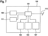
- Figure 7 schematically shows a simplified block diagram of a computer system 100 for implementing the data processing system 31 for processing acquired intensity values for x-rays penetrating the inspection object or for implementing the control unit 33. It goes without saying that the data processing system 31 and control unit 33 can also be implemented using a single computer system 100.
- the data processing system 31 for processing and evaluating the intensity values detected by the X-ray inspection system 1 can take place in the computer system 100, which is arranged locally in or on the X-ray inspection system.
- the computer system 100 for example coupled via a computer network, to be arranged at a central location in the manner of a mainframe computer system, in particular for a plurality of X-ray inspection systems.
- the computer system 100 it is also possible for the computer system 100 to be formed by a plurality of computer systems connected to one another via a computer network and thus spatially distributed.
- the computer system 100 has at least one processor 101 controllable by means of software.
- Software means for example computer programs for implementing the desired functions, are stored in at least one first memory 103 when the computer program is executed in the at least one processor 101.
- At least one second memory 105 is provided as a working memory for data to be processed and intermediate or final results.
- a third memory 107 can be provided in which comparison values for specific material size values are stored in the form of a database; this can be, for example, specific variables of known materials that influence the absorption of X-rays, in particular the density and / or the mass attenuation coefficient and / or the effective number of nuclei of these materials.
- the data processing system 100 also has input means 109, such as a keyboard, a touchpad, a pointer input unit (computer mouse) or the like, or a variant of some of these means or a combination thereof specifically tailored to simple operation.
- input means 109 such as a keyboard, a touchpad, a pointer input unit (computer mouse) or the like, or a variant of some of these means or a combination thereof specifically tailored to simple operation.
- An imaging output means 111 such as at least one screen or monitor 35 ( Figure 1 ) intended.
- the computer system 100 is coupled to the X-ray inspection system 1 via a data interface 113, i.e. depending on the function to be implemented with actuators (such as motors 4, 29, radiation sources 7, 9 etc.) or sensors (e.g. detector unit 25).
- actuators such as motors 4, 29, radiation sources 7, 9 etc.
- sensors e.g. detector unit 25.
- processor can refer to any electronic device or circuit or part of an electronic device or circuit which processes electronic data from registers and / or a memory, to convert electronic data into other electronic data or to generate corresponding output data from input data, which can be stored in registers and / or a memory.
- the computer system 100 can comprise a processor 101 or a plurality of processors.
- the computer system 100 is preferably implemented as a combination of hardware, firmware and software.
- the methods described here can be implemented partially or completely as software means stored on a machine-readable medium, which can be read into the computer system 100 and executed for implementation.
- a machine-readable medium can be configured for any mechanism for storing, transmitting, or receiving information in a form that is readable by a computer.
- Read-only memory (ROM), random access memory (RAM), magnetic storage disks, optical storage media, and flash storage media are mentioned here as non-exhaustive examples.
- the software means can also be in the form of a data stream as optical, acoustic or other signals forwarded (e.g. as carrier waves, infrared signals, digital signals, etc.) that are transmitted via appropriate interfaces, for example antennas, which transmit these signals and / or can be received, transmitted.
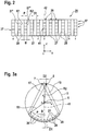
- Figure 2 shows a development of a first embodiment of the detector unit 25 in a simplified representation, that is, there are significantly fewer rows 37 and columns 39 of FIG Detector elements 27 as indicated in reality.
- the individual detector elements 27 are each indicated in a simplified manner by a rectangle.
- the xyz coordinate system is also for orientation and corresponding to Figure 1 shown.
- the columns 39 are numbered positive or negative starting from the center outwards.
- the straight line is denoted by 42 which results from a projection of the axis of rotation 5 from a point between the radiation sources 7, 9 onto the detector unit 25.
- the straight line 41 of the Figure 1 is also indicated for orientation.
- the detector unit 25 does not consist of a detector field or detector array that is geometrically completely (ie fill factor 100%) occupied by detector elements 27, but of detector columns 39 spaced from one another by gaps 28.
- the width of the gaps 28 corresponds to the distance D1 between two adjacent detector elements 27.
- the individual Detector elements 27 have a width B.
- the distance from a right edge K1 of a detector element 27 'to the right edge K2 of the immediately adjacent detector element 27 "in the same line 37 is marked with P and is referred to by the technical term pitch.
- the geometric efficiency ( engl, geometric efficiency) or the line density of the detector unit 25 is defined as the quotient B / P.
- FIG. 3 is a schematic plan view of the X-ray inspection system 1 of FIG Figure 1 in direction z, ie in the direction of the axis of rotation 5.
- the xyz coordinate system is also for orientation and corresponding to Figure 1 registered.
- the two radiation sources 7 and 9 are shown on the circumferential line of the gantry 3, which are arranged at a distance D2 from one another on a circular path running to the axis of rotation 5 with the radius R2.
- the detector unit 25 with the detector elements 27 is shown arranged on a concentric circular path with radius R1.
- the second distance D2 between the at least two independently controllable x-ray sources 7, 9 is shown in FIG Figure 3a
- the exemplary embodiment shown is set such that D 2 ⁇ B D 1, where B is the width of a detector element 27 in the circumferential direction of the gantry 3; that is to say, the width D1 of a gap 28 is at least as great as the width of a detector element 27.
- the distances, especially the distance D2 are not shown to scale for the sake of simplicity.
- n 2
- the second distance D2 of the radiation sources 7, 9 is set to approximately the distance of the width B of a detector element 27, at least every second detector line 29 can be omitted.
- the pitch P is then exactly double the width B.
- 50% or a detector line density of 50% for the geometric efficiency defined above In conventional x-ray systems of the generic type with one radiation source or several radiation sources which, however, are not spaced according to the invention, it is necessary to achieve the desired triggering of the virtual detector in the measuring field to occupy the detector unit 25 with detector elements 27 in such a way that a detector row density of approximately 100 % results.
- Such detector units are complex and expensive.
- gaps 28 are created between the individual detector gaps 39 by means of the first distance D1, the width of which is preferably set in a range from more than 100% to a maximum of 250% of the width B of a detector element 27 can be. Even at a distance D1 that is equal to the width B of a detector element 27, the effort with regard to the detector elements 27 and their wiring is halved, with essentially the same triggering in the measuring field being achieved as in systems with a focus and a detector unit with 100 % Fill factor.
- the inventors have also found that the first distance D1, i.e. the width of the gap 28 between the individual detector rows 39 can even be increased to twice the value of the width B of a detector element 27 - with still acceptable quality losses. This results in a geometric efficiency of 25% or a detector line density of 25%.
- a detector element 27 can be, for example, a scintillator pixel that receives X-rays and converts them into light pulses, which can then be converted into an electrical measurement signal via an integrated photodiode.
- the structure is complex, and the wiring of the individual detectors 27 is particularly complicated.
- FIG. 3 is a schematic plan view of the X-ray inspection system 1 of FIG Figure 1 in direction z, ie in the direction of the axis of rotation 5, which is not part of the invention, with an alternatively designed detector unit 25 ', ie a modification compared to FIG Figure 3a .
- the xyz coordinate system is also for orientation and corresponding to Figure 1 registered.
- the two radiation sources 7, 9 are shown on the circumferential line of the gantry 3, which are arranged at a distance D2 from one another on a circular path running to the axis of rotation 5 with the radius R2.
- the detector unit 25 ' Arranged opposite the radiation sources 7, 9 is the detector unit 25 'with the detector elements 27, which are arranged on a circular path with radius R1' opposite approximately a point between the radiation sources 7 and 9.
- R1' 2 R2
- ie R1 ' is approximately twice as large as R2.
- the second distance D2 is in the Figure 3b
- the embodiment shown is set between the at least two independently controllable X-ray sources 7, 9 such that D 2 ⁇ B D 1 applies, where B is the width of a detector element 27 in the circumferential direction; also at Figure 3b it should be noted that the distances, especially the distance D2, are not drawn to scale for the sake of simplicity.
- FIG 4 shows details of the detector unit of Figure 3a with detector elements arranged one above the other from the point of view of the radiation sources 7, 9, first 27a and second 27b, in order to enable a dual-energy or multi-energy evaluation. That is, each detector element 27 is set up for the detection of two energy ranges (or frequency ranges) from the X-ray spectrum of the radiation sources 7, 9, in that the first detector elements 27a are set up to detect X-rays from the first energy range and the second detector elements 27b are set up to detect X-rays are set up for a second energy range. For this purpose, a second detector element 27b is arranged below a first detector element 27a.
- the first detector elements 27a and the second detector elements 27b each supply an associated measured value, so that measured values are available for two energy ranges.
- the multi-energy evaluation can be based on this; for example in order to be able to determine not only a probable density but also the probable effective ordinal number Z eff of a material in a spatial element (voxel) of the examination area.
- a detector element 27 actually consists of two Detectors arranged one above the other, as detector elements 27, can for example be taken from the above EP 1 186 909 known detector elements are used.
- the detector unit 25 is essentially only constructed from detector columns 39 spaced apart from one another, the construction of the detector elements can be further simplified, particularly with regard to multiple energy evaluation.
- FIG. 13 shows a plan view of an exemplary alternative of the detector unit 25 of FIG Figure 4 , which is not part of the invention, with first 27a and second 27b arranged next to each other detector elements for a multi-energy evaluation.
- Figure 6 shows a schematic plan view of the gantry 3 of a further development of the X-ray inspection system of FIG Figure 1 with the direction of view along the axis of rotation 5 with the further developed detector unit 25 of FIG Figure 5 . Also in the example of Figures 5 and 6 a gap 28 is provided between adjacent detector elements 27a, 27b.
- the Figures 5 and 6 the actual distance between two first detector elements 27a or two second detector elements 27b is enlarged to twice the width B of one of the detector elements 27a, 27b; that is, D 1 / B ⁇ 200% applies to the ratio. This reduces the resolution of the information about the inspection object detected with the first or second detector elements.
- the first detector elements 27a and second detector elements 27b are in the Figures 5 and 6 not like in the execution of the Figure 4 one above the other, but arranged side by side. This additionally simplifies the construction of the detector unit 25, in particular the wiring of the individual detector elements 27 does not cause any impairment more, since none of the detector elements 27 lies in the beam path of another detector element in the case of a multiple energy evaluation.
- the first distance D1 of the individual first 39a and second 39b detector columns is here also set to more than the width B of a detector element 27a, 27b ( ie D 1 / B 100%).
- each detector element 27a, 27b has at least one gap 28 available, which can be used, for example, for a simplified wiring of the detector element 27a or 27b.
- the radius of curvature of the detector units 25 of the Figures 4 and 6th in the circumferential direction, as in the Figure 3b shown, be designed according to a circular path with the radius R1 'around the center of the foci.
- the space requirement for the detector unit increases, but all of the individual detector elements 27 can be equally better aligned with the radiation sources 7, 9 or 6, 7, 8, 9.
Description
Die Erfindung betrifft im Allgemeinen eine Röntgenprüfanlage. Die Erfindung betrifft im Besonderen eine Röntgenprüfanlage zur zerstörungsfreien Inspektion von Objekten.The invention relates generally to an X-ray inspection system. The invention relates in particular to an X-ray inspection system for the non-destructive inspection of objects.
Die Anforderungen an Röntgenprüfanlagen zur Inspektion von Objekten, besonders zur Erkennung von Gefahrenstoffen, schreiten hinsichtlich einer Erhöhung des Gepäckdurchsatzes bei selbstverständlich gleich hoher Erkennungsrate, d.h. Detektionssicherheit, ständig voran. Andererseits sind Röntgenprüfanlagen von der Art eines Computertomographen (CT) sehr komplexe Vorrichtungen. Beispielsweise sind die in CT-Vorrichtungen benötigten Detektoreinheiten, besonders bei CTs mit Dual-Energie-Funktionalität, sehr aufwendig und aufgrund der für die angestrebten Auflösungen erforderlichen hohen Packungsdichte von Detektorelementen kompliziert und damit teuer.The requirements for X-ray inspection systems for the inspection of objects, especially for the detection of hazardous substances, are constantly advancing with regard to an increase in baggage throughput with, of course, the same high detection rate, i.e. detection reliability. On the other hand, X-ray inspection systems of the computed tomography (CT) type are very complex devices. For example, the detector units required in CT devices, particularly in the case of CTs with dual-energy functionality, are very expensive and, due to the high packing density of detector elements required for the desired resolutions, are complicated and therefore expensive.
Es ist eine Aufgabe der vorliegenden Erfindung, eine Röntgenprüfanlage für die Detektion von Materialien, insbesondere Gefahrenstoffen, in einem Objekt, insbesondere einem Gepäckstück, vorzuschlagen, die eine Vereinfachung beim apparativen Aufwand erreicht. Es ist insbesondere eine Aufgabe der Erfindung, trotz geringeren apparativen Aufwands eine geforderte Detektionssicherheit zu erreichen.It is an object of the present invention to propose an X-ray inspection system for the detection of materials, in particular hazardous substances, in an object, in particular a piece of luggage, which simplifies the outlay on equipment. In particular, it is an object of the invention to achieve the required detection reliability despite the lower outlay on equipment.
Diese Aufgabe wird mit den Merkmalen einer Röntgenprüfanlage gemäß dem unabhängigen Anspruch 1 gelöst. Weitere Merkmale und Details der Erfindung ergeben sich aus den Unteransprüchen, der Beschreibung und den Zeichnungen. Dabei gelten Merkmale und Details, die im Zusammenhang mit der erfindungsgemäßen Röntgenprüfanlage beschrieben sind, auch im Zusammenhang mit dem erfindungsgemäßen Verfahren gemäß dem unabhängigen Anspruch 5 und jeweils umgekehrt, sodass bezüglich der Offenbarung der einzelnen Erfindungsaspekte stets wechselseitig Bezug genommen wird bzw. werden kann.This object is achieved with the features of an X-ray inspection system according to
Ein Kerngedanke der Erfindung liegt in der Erkenntnis, bei einer Röntgenprüfanlage mit rotierender Strahlungsquelle und mit (i) einer gegenüberliegend mitrotierend angeordneten Detektoreinheit oder mit (ii) einer feststehend um die von der rotierender Strahlungsquelle beschriebenen Kreisbahn herum angeordneten ringförmigen Detektoreinheit, durch eine Erhöhung der Anzahl der Strahlungsquellen, beispielsweise der Röntgenbrennpunkte (Foci), die Anzahl der benötigten Detektorelemente in Umfangsrichtung der Rotation zu verringern. Dadurch kann der Füllfaktor (Verhältnis der sensitiven Fläche zur Gesamtfläche) der Detektoreinheit und/oder der Detektorelemente gegenüber den bekannten Röntgenprüfanlagen reduziert werden. Beispielsweise ermöglicht eine Erhöhung der Strahlungsquellen von eins auf zwei, d.h. eine Verdopplung, wenigstens eine Halbierung der Anzahl der benötigten Detektorelemente an der Detektoreinheit in Rotationsrichtung.A core idea of the invention lies in the knowledge that in an X-ray inspection system with a rotating radiation source and with (i) a detector unit arranged opposite to rotate with it or with (ii) an annular detector unit arranged in a stationary manner around the circular path described by the rotating radiation source, by increasing the number the radiation sources, for example the X-ray focal points (foci), to reduce the number of detector elements required in the circumferential direction of the rotation. As a result, the fill factor (ratio of the sensitive area to the total area) of the detector unit and / or the detector elements can be reduced compared to the known X-ray inspection systems. For example, increasing the number of radiation sources from one to two, ie doubling, at least halving the number of detector elements required on the detector unit in the direction of rotation.
Die Erfinder haben zunächst erkannt, dass wenn der Abstand (in Rotationsrichtung) zwischen den wenigstens zwei Strahlungsquellen in der Größenordnung der Breite eines Detektorelements eingestellt wird, der Abstand zwischen den Detektorelementen in Umfangrichtung der Rotation ohne Auswirkungen auf die Auflösung auf wenigstens die Breite eines Detektorelements erhöht werden kann. Mit anderen Worten kann jedes zweite Detektorelement in Wegfall gebracht werden. Infolgedessen kann vorteilhaft aufgrund des freiwerdenden Raums in der Detektoreinheit der Aufbau der Detektorelemente bzw. der Detektoreinheit vereinfacht werden. Zwischen zwei benachbarten Detektorelementen befindet sich dann eine Lücke mit der Breite eines Detektorelements. Diese Lücke steht zusätzlich beispielsweise für die Verdrahtung der Detektorelemente zur Verfügung. Im Ergebnis sind mit der so vereinfachten Röntgenprüfanlage Röntgenaufnahmen realisierbar, welche die gleiche Qualität, insbesondere die gleiche Auflösung aufweisen wie Röntgenaufnahmen, die mit einer vergleichbaren Röntgenprüfanlage mit nur einer Strahlungsquelle und der üblichen hohen Anzahl von Detektorelementen, die in Umfangsrichtung lückenlos auf der Detektoreinheit angeordnet sind, angefertigt wurden.The inventors first recognized that if the distance (in the direction of rotation) between the at least two radiation sources is set in the order of magnitude of the width of a detector element, the distance between the detector elements in the circumferential direction of the rotation increases to at least the width of a detector element without affecting the resolution can be. In other words, every second detector element can be eliminated. As a result, the structure of the detector elements or the detector unit can advantageously be simplified due to the space freed up in the detector unit. A gap with the width of a detector element is then located between two adjacent detector elements. This gap is also available, for example, for wiring the detector elements. As a result, the simplified X-ray inspection system enables X-ray recordings to be made which have the same quality, in particular the same resolution, as X-ray recordings made with a comparable X-ray inspection system with only one radiation source and the usual high number of detector elements that are arranged on the detector unit without any gaps in the circumferential direction , were made.
Die Erfinder haben weiter erkannt, dass wenn der Abstand zwischen den wenigstens zwei Strahlungsquellen in der Größenordnung der Breite eines Detektorelements eingestellt wird, der Abstand zwischen den Detektorelementen in Umfangrichtung der Rotation auf bis zu der doppelten, ggf. bis auf die 2,5-fachen Breite eines Detektorelements erhöht werden kann. Diese Vergrößerung der Lücken hat dann jedoch eine Verringerung bei der Qualität der Röntgenaufnahmen zur Folge. Dies bedeutet, dass die Lückenbreite in dem angegebenen Umfang im Hinblick auf eine geforderte Qualität, insbesondere Auflösung, der Röntgenbilder, entsprechend eingestellt werden kann. Im Ergebnis lassen sich sogar mehr als die Hälfte der Detektorelemente einer Detektoreinheit mit 100% Füllfaktor einsparen. D.h., mit dem Mehraufwand für die zweite oder weitere Röntgenstrahlungsquellen bzw. Foci kann eine entsprechende Reduzierung des Aufwands bei der Detektoreinheit neben zusätzlichen Vorteilen erreicht werden. Damit ist eine erfindungsgemäße Röntgenprüfanlage kostengünstiger.The inventors have further recognized that if the distance between the at least two radiation sources is set in the order of magnitude of the width of a detector element, the distance between the detector elements in the circumferential direction of the rotation is up to twice, possibly up to 2.5 times Width of a detector element can be increased. However, this enlargement of the gaps then results in a reduction in the quality of the X-ray images. This means that the gap width can be adjusted accordingly to the specified extent with regard to a required quality, in particular resolution, of the x-ray images. As a result, even more than half of the detector elements of a detector unit with a 100% fill factor can be saved. That is to say, with the additional expenditure for the second or further x-ray sources or foci, a corresponding reduction in the expenditure for the detector unit can be achieved in addition to additional advantages. An X-ray inspection system according to the invention is therefore more cost-effective.
Eine erfindungsgemäße Röntgenprüfanlage zur zerstörungsfreien Inspektion von Objekten kann somit aufweisen: wenigstens zwei um eine Rotationsachse in einer Rotationsebene drehbare Röntgenstrahlungsquellen (auch Foci bzw. Brennflecke genannt) zum Erzeugen jeweils eines einen Untersuchungsbereich durchsetzenden Strahlenbündels und eine der wenigstens einen Röntgenstrahlungsquelle gegenüberliegend angeordnete Detektoreinheit mit Detektorelementen für Röntgenstrahlen. Ein Inspektionsobjekt kann mittels einer Transporteinrichtung entlang einer Förderrichtung durch den Untersuchungsbereich gefördert werden, wobei die Förderrichtung für das Inspektionsobjekt im Wesentlichen senkrecht zu der Rotationsebene verläuft.An X-ray inspection system according to the invention for the non-destructive inspection of objects can thus have: at least two X-ray sources (also known as foci or focal spots) rotatable about an axis of rotation in a plane of rotation for generating a beam of rays passing through an examination area and a detector unit with detector elements arranged opposite the at least one X-ray source X-rays. An inspection object can be conveyed through the examination area by means of a transport device along a conveying direction, the conveying direction for the inspection object running essentially perpendicular to the plane of rotation.
Zueinander in Umfangsrichtung der Rotation der Röntgenstrahlungsquellen benachbarte Detektorelemente mit einem ersten Abstand D1 so beabstandet, dass sie eine Lücke bilden; d.h., der Füllfaktor der Detektoreinheit ist damit kleiner als 100%.Detector elements which are adjacent to one another in the circumferential direction of the rotation of the X-ray sources are spaced apart by a first distance D1 in such a way that they form a gap; i.e. the fill factor of the detector unit is less than 100%.
Die wenigstens zwei unabhängig ansteuerbaren Röntgenstrahlungsquellen (Foci) sind in Umfangrichtung in der Rotationsebene mit einem zweiten Abstand D2 beabstandet angeordnet. Bevorzugt sind die wenigstens zwei unabhängig ansteuerbaren Röntgenstrahlungsquellen so beabstandet, dass sich entlang einer ersten Geraden, die (a) durch das Rotationszentrum der Foci und (b) senkrecht zu einer zweiten Geraden verläuft, die (i) von dem Punkt auf der Rotationsbahn der Foci, der in der Mitte zwischen den beiden Foci liegt, und (ii) durch das Rotationszentrum der Foci verläuft, wenigstens in einem Abschnitt um das Rotationszentrum eine gewünschte räumliche Auflösung durch die Kombination der beiden Foci mit den beabstandeten Detektorelementen der Detektoreinheit ergibt. D.h., dieser Abschnitt der ersten Gerade entspricht im Wesentlichen dem Untersuchungsbereich oder Messfeld der Röntgenprüfanlage. Mit anderen Worten kann der das Messfeld bildende Abschnitt der ersten Geraden als virtueller Detektor interpretiert werden, der die benötigte bzw. geforderte räumliche Auflösung aufweist. Aufgrund der Lücken zwischen den Detektorelementen wird der bei CT-Anlagen zunächst ein systembedingter Effekt zusätzlich verstärkt, nämlich dass im Halbkreis der Foci über dem virtuellen Detektor zu den Foci hin eine Überabtastung und im Halbkreis unter dem virtuellen Detektor zu den Detektorelementen hin eine Unterabtastung erfolgt. Da sich die Anordnung aus den wenigstens zwei Röntgenstrahlungsquellen und der Detektoreinheit um das Inspektionsobjekt herum dreht, gleichen sich die Unter- und Überabtastung aus und es wird für das Inspektionsobjekt die Auflösung des virtuellen Detektors erreicht.The at least two independently controllable x-ray sources (foci) are arranged at a second distance D2 in the circumferential direction in the plane of rotation. The at least two independently controllable X-ray sources are preferably spaced apart such that along a first straight line that runs (a) through the center of rotation of the foci and (b) perpendicular to a second straight line that (i) from the point on the rotational path of the foci , which lies in the middle between the two foci, and (ii) runs through the center of rotation of the foci, at least in a section around the center of rotation results in a desired spatial resolution through the combination of the two foci with the spaced detector elements of the detector unit. This means that this section of the first straight line essentially corresponds to the examination area or measuring field of the X-ray inspection system. In other words, the section of the first straight line that forms the measurement field can be interpreted as a virtual detector which has the required or required spatial resolution. Due to the gaps between the detector elements, a system-related effect is initially additionally reinforced in CT systems, namely that oversampling takes place in the semicircle of the foci above the virtual detector towards the foci and undersampling takes place in the semicircle below the virtual detector towards the detector elements. Since the arrangement of the at least two x-ray sources and the detector unit rotates around the inspection object, the undersampling and oversampling are balanced out and the resolution of the virtual detector is achieved for the inspection object.
Das Verhältnis D1/B des ersten Abstands D1 zu einer Breite B eines ersten Detektorelements in Umfangsrichtung beträgt aufgrund der Lücken mehr als 100% und höchstens 250%. D.h., die Lücke ist größer als die Breite B und maximal das 2,5-fache der Breite B eines Detektorelements. Das Verhältnis D1/B des ersten Abstands D1 zu der Breite B eines ersten Detektorelements in Umfangsrichtung kann in bestimmten Ausführungen mindestens mehr als 110%, oder mehr als 125%, oder mehr als 150%, oder mehr als 175% oder mehr als 200% betragen.The ratio D1 / B of the first distance D1 to a width B of a first detector element in the circumferential direction is more than 100% and at most 250% due to the gaps. Ie the gap is larger than the width B and a maximum of 2.5 times the width B of a detector element. The ratio D1 / B of the first distance D1 to the width B of a first detector element in the circumferential direction can in certain embodiments be at least more than 110%, or more than 125%, or more than 150%, or more than 175% or more than 200%. be.
Wie bereits erläutert, vereinfacht sich durch die Lücken der Aufbau der Detektoreinheit. Dies gilt auch für die Detektorelemente. Beispielsweise können die Lücken zwischen den Detektorspalten zur Verdrahtung der Detektorelemente genutzt werden. Da für die Detektorelemente in eine Detektorspalte aufgrund der Lücken mehr Platz zur Verfügung steht, können die Detektorelemente mit der Detektionsfläche besser in Richtung der Foci ausgerichtet werden, indem die Detektionsfläche gegenüber einer Tangente an die Rotationsbahn zu den Foci hin geneigt angeordnet ist. Ebenso reduzieren sich auch Anforderungen an die Präzision für andere Teile der Anlage. Beispielsweise muss ein Röntgenraster bzw. Streustrahlenraster (anti-scatter grid, Bucky-Blende), das vor der Detektoreinheit angebracht wird, um den Einfall von Streustrahlung auf die Detektorelemente zu reduzieren. Mit dieser Maßnahme wird der Kontrast des Röntgenbildes erhöht. Das Streustrahlenraster entspricht im Prinzip den Kollimatoren an der Röntgenstrahlenquelle. Aufgrund der Lücken zwischen den Detektorelementen vereinfacht sich die Fertigung des Streustrahlenrasters entsprechend.As already explained, the structure of the detector unit is simplified by the gaps. This also applies to the detector elements. For example, the gaps between the detector columns can be used for wiring the detector elements. Since there is more space available for the detector elements in a detector column due to the gaps, the detector elements with the detection surface can be better aligned in the direction of the foci in that the detection surface is inclined with respect to a tangent to the rotational path towards the foci. The precision requirements for other parts of the system are also reduced. For example, an X-ray grid or anti-scatter grid (bucky screen) must be installed in front of the detector unit in order to reduce the incidence of scattered radiation on the detector elements. This measure increases the contrast of the X-ray image. The anti-scatter grid corresponds in principle to the collimators on the X-ray source. Due to the gaps between the detector elements, the manufacture of the anti-scatter grid is simplified accordingly.
Unter Röntgenstrahlungsquelle wird hier ein Punkt verstanden, von dem erzeugte Röntgenstrahlen bestimmungsgemäß ausgehen. D.h., Röntgenstrahlungsquelle steht hier synonym für Röntgenstrahlen-Focus (kurz Focus) oder Röntgenstrahlen-Brennfleck (kurz: Brennfleck). Die eigentliche Erzeugung der Röntgenstrahlen erfolgt in einer Röntgenstrahlenerzeugungseinrichtung, wie beispielsweise einer Röntgenröhre. D.h., die erfindungsgemäßen wenigstens zwei unabhängig aktivierbaren Röntgenstrahlungsquellen (Foci bzw. Brennflecke) können eine gemeinsame Röntgenstrahlenerzeugungseinrichtung aufweisen. Es können aber auch zwei unabhängig ansteuerbare bzw. aktivierbare Röntgenstrahlungserzeugungseinrichtungen, d.h. für jeden Focus bzw. Brennfleck eine eigene Röntgenstrahlenerzeugungseinrichtung, vorgesehen sein. Entsprechend ist klar, dass für eine Ausführung mit z.B. vier unabhängig aktivierbaren Foci bzw. Brennflecken, eine Röntgenstrahlungserzeugungseinrichtung mit vier unabhängig aktivierbaren Foci, oder zwei Röntgenstrahlungserzeugungseinrichtungen mit jeweils zwei unabhängig aktivierbaren Foci, oder auch vier unabhängig aktivierbare Röntgenstrahlungserzeugungseinrichtungen verwendet werden können.An X-ray source is understood here to be a point from which generated X-rays originate as intended. That is, the X-ray source is synonymous here with X-ray focus (short focus) or X-ray focal point (short: focal point). The actual generation of the X-rays takes place in an X-ray generation device, such as an X-ray tube. That is, the at least two independently activatable x-ray sources (foci or focal spots) according to the invention can have a common x-ray generating device. However, two independently controllable or activatable X-ray generation devices, that is to say a separate X-ray generation device for each focus or focal point, can also be provided. Accordingly, it is clear that for an embodiment with, for example, four independently activatable foci or focal spots, one x-ray generating device with four independently activatable foci, or two x-ray generating devices each with two independently activatable foci, or four independently activatable x-ray generating devices can be used.
Dadurch, dass erfindungsgemäß wenigstens eine zweite Röntgenstrahlungsquelle (Focus/Brennfleck) vorgesehen ist, werden bei gleicher Detektionsauflösung der Anlage, aufgrund der Lücken zwischen den Detektorelementen insgesamt weniger Detektionselemente benötigt. Dadurch vereinfacht sich der Aufwand für die Detektoreinheit entsprechend. Zusätzlich vereinfacht sich der Aufbau der Detektoreinheit, da bei einem deutlich kleineren physikalischen Füllfaktor im Wesentlichen ein gleicher effektiver Füllfaktor (bei der virtuellen Detektoreinheit) erreicht wird, wie bei einer herkömmlichen Detektoreinheit, bei der der Füllfaktor annähernd 100% beträgt. Die mögliche Reduktion beim Aufwand hinsichtlich der Detektoreinheit kompensiert den Mehraufwand durch die wenigstens zweite Röntgenstrahlungsquelle bei Weitem. Es ist davon auszugehen, dass Kostenvorteile wenigstens im Bereich von 2 bis 4 Röntgenstrahlungsquellen erzielt werden können.Because at least one second X-ray source (focus / focal point) is provided according to the invention, fewer detection elements are required overall due to the gaps between the detector elements, given the same detection resolution of the system. This simplifies the effort for the detector unit accordingly. In addition, the construction of the detector unit is simplified, since with a significantly smaller physical fill factor, essentially the same effective fill factor (with the virtual detector unit) is achieved as with a conventional detector unit, in which the fill factor is approximately 100%. The possible reduction in the effort with regard to the detector unit by far compensates for the additional effort due to the at least second x-ray source. It can be assumed that cost advantages can be achieved at least in the range of 2 to 4 x-ray sources.
Erfindungsgemäß sind die ersten Detektorelemente auf einer ersten Kreisbahn mit einem ersten Radius R1' angeordnet. Die wenigstens zwei unabhängig ansteuerbaren Röntgenstrahlungsquellen sind in der Rotationsebene auf einer zweiten Kreisbahn mit einem zweiten Radius R2 um die Rotationsachse angeordnet, wobei die erste Kreisbahn um einen Punkt auf der zweiten Kreisbahn mittig zu den wenigstens zwei unabhängig ansteuerbaren Röntgenstrahlungsquellen angeordnet ist. Für den zweiten Abstand D2 zwischen den wenigstens zwei unabhängig ansteuerbaren Röntgenstrahlungsquellen gilt dann: ![]()
![]()
In bestimmten Ausführungen, beispielsweise in solchen, bei denen die Röntgenprüfanlage eine um den Untersuchungsbereich drehbare Gantry aufweist, können die Detektorelemente und die wenigstens zwei Röntgenstrahlungsquellen im Wesentlichen auf derselben Kreisbahn angeordnet sein, sodass der erste Radius R1 gleich dem zweiten Radius R2 ist bzw. der erste Radius R1' ungefähr doppelt so groß wie der zweite Radius R2 ist.In certain embodiments, for example in those in which the X-ray inspection system has a gantry that can be rotated around the examination area, the detector elements and the at least two X-ray sources can be arranged essentially on the same circular path, so that the first radius R1 is equal to the second radius R2 first radius R1 'is approximately twice as large as the second radius R2.
Grundsätzlich hat es sich bewährt, den zweiten Abstand D2 zwischen den wenigstens zwei Röntgenstrahlungsquellen bevorzugt ungefähr gleich oder kleiner der Breite B eines Detektorelements einzustellen. Der zweite Abstand D2 wird bevorzugt so eingestellt, dass der oben erläuterte, das Messfeld bildende virtuelle Detektor die geforderte räumliche Auflösung aufweist.In principle, it has proven useful to set the second distance D2 between the at least two x-ray sources, preferably approximately equal to or less than the width B of a detector element. The second distance D2 is preferably set in such a way that the above-explained virtual detector forming the measurement field has the required spatial resolution.
Erfindungsgemäß bestehen die Detektorelemente aus ersten Detektorelementen, die für die Detektion von Röntgenstrahlung in einem ersten Energiebereich (bzw. Frequenzbereich) eingerichtet sind. Weiter sind zweite Detektorelementen, die für die Detektion von Röntgenstrahlung in einem zweiten Energiebereich (bzw. Frequenzbereich) eingerichtet sind, vorgesehen. Die zweiten Detektorelemente haben bevorzugt dieselbe Breite B wie die ersten Detektorelemente.According to the invention, the detector elements consist of first detector elements which are set up for the detection of X-rays in a first energy range (or frequency range). Second detector elements, which are set up for the detection of X-rays in a second energy range (or frequency range), are also provided. The second detector elements preferably have the same width B as the first detector elements.
Dabei ist - mit Bezug auf den Strahlengang - unter jeweils einem ersten Detektorelement jeweils eines der zweiten Detektorelemente angeordnet. Bevorzugt sind dabei die ersten Detektorelemente für Röntgenstrahlen aus einem niedrigeren Energiebereich ausgelegt und die darunter angeordneten zweiten Detektorelemente für Röntgenstrahlen aus einem höheren Energiebereich ausgelegt. Mit einer solchen Detektoranordnung kann eine Mehrenergie- bzw. Dual-Energy-Auswertung erfolgen.With reference to the beam path, one of the second detector elements is in each case arranged under a first detector element. The first detector elements are preferably designed for X-rays from a lower energy range and the second detector elements arranged below are designed for X-rays from a higher energy range. A multi-energy or dual-energy evaluation can be carried out with such a detector arrangement.
Bei den zwei unterschiedlichen Arten von Detektorelementen ist besonders vorteilhaft, dass die Verdrahtung keines der Detektorelemente im Strahlengang eines anderen Detektorelements angeordnet werden muss. Dies vereinfacht die Verdrahtung der Detektorelemente der Detektoreinheit deutlich, da für die Verdrahtung zusätzlich die Lücke genutzt werden kann.With the two different types of detector elements, it is particularly advantageous that the wiring does not have to be arranged in any of the detector elements in the beam path of another detector element. This significantly simplifies the wiring of the detector elements of the detector unit, since the gap can also be used for the wiring.
Mit der Röntgenprüfanlage der vorstehenden Weiterbildungen kann eine Mehrenergie- bzw. Dual-Energy-Auswertung erfolgen, wodurch sich für einzelne Raumelemente des Inspektionsobjekts die effektive Kernzahl (Zeff) des dort befindlichen Materials bestimmen lässt.With the X-ray inspection system of the above developments, a multi-energy or dual-energy evaluation can be carried out, whereby the effective core number (Zeff) of the material located there can be determined for individual spatial elements of the inspection object.
Die Detektorelemente sind in der Detektionseinheit in Richtung der Rotationsachse bzw. in Förderrichtung des Inspektionsobjekts jeweils in Reihen mit mehreren Detektorelementen als Detektorspalte angeordnet.The detector elements are arranged in the detection unit in the direction of the axis of rotation or in the conveying direction of the inspection object in each case in rows with a plurality of detector elements as detector gaps.
Weiter wurde festgestellt, dass, wenn die Röntgenprüfanlage eine Anzahl n, mit n größer gleich 2, unabhängig ansteuerbarer Röntgenstrahlungsquellen aufweist, es von Vorteil ist, die Prüfanlage so einzurichten, dass die n unabhängig ansteuerbaren Röntgenstrahlungsquellen im Betrieb der Röntgenprüfanlage abwechselnd bzw. nacheinander bzw. der Reihe nach mit wenigstens der n-fachen Frequenz angesteuert werden als dies bei gleicher Rotationsgeschwindigkeit an einer Röntgenprüfanlage mit nur einer einzigen Röntgenstrahlungsquelle erfolgt. Alternativ kann die Frequenz reduziert werden, wenn die Rotationsgeschwindigkeit entsprechend reduziert wird. Dann können in bestimmten Ausführungen Röntgenbilder mit im Wesentlichen der gleichen Auflösung rekonstruieren werden. Entsprechend werden die Detektorelemente ebenfalls mit der n-fachen Frequenz ausgelesen.It was also found that if the X-ray inspection system has a number n, with n greater than or equal to 2, independently controllable X-ray sources, it is advantageous to set up the inspection system in such a way that the n independently controllable X-ray sources alternate or one after the other or when the X-ray inspection system is in operation. are controlled sequentially with at least n times the frequency than with the same rotation speed on an X-ray inspection system with only a single one X-ray source takes place. Alternatively, the frequency can be reduced if the speed of rotation is reduced accordingly. In certain embodiments, x-ray images can then be reconstructed with essentially the same resolution. Accordingly, the detector elements are also read out at n times the frequency.
Weiter wurde festgestellt, dass, wenn die Röntgenprüfanlage eine Anzahl n, mit n größer gleich 2, unabhängig ansteuerbarer Röntgenstrahlungsquellen aufweist, es von Vorteil ist, die Prüfanlage so einzurichten, dass die n unabhängig ansteuerbaren Röntgenstrahlungsquellen jeweils Röntgenstrahlen mit einer wenigstens n-fach größeren Strahlungsintensität abgeben als dies bei gleicher Rotationsgeschwindigkeit in einer Röntgenprüfanlage mit einer einzigen Röntgenstrahlungsquelle erfolgt.It was also found that if the X-ray inspection system has a number n, with n greater than or equal to 2, independently controllable X-ray sources, it is advantageous to set up the inspection system in such a way that the n independently controllable X-ray sources each have X-rays with an at least n-fold greater radiation intensity output than this takes place at the same speed of rotation in an X-ray inspection system with a single X-ray source.
Die Röntgenprüfanlage kann weiter eine Transporteinrichtung aufweisen, welche zumindest teilweise in einer Einhausung der Röntgenprüfanlage angeordnet und eingerichtet ist, ein Inspektionsobjekt durch die Röntgenprüfanlage hindurch in Förderrichtung im Wesentlichen senkrecht zur Rotationsebene der Röntgenstrahlungsquellen zu transportieren. Die Transporteinrichtung kann eingerichtet sein, ein Inspektionsobjekt kontinuierlich oder schrittweise durch den Untersuchungsbereich zu transportieren.The X-ray inspection system can furthermore have a transport device which is arranged at least partially in a housing of the X-ray inspection system and is set up to transport an inspection object through the X-ray inspection system in the conveying direction essentially perpendicular to the plane of rotation of the X-ray sources. The transport device can be set up to transport an inspection object continuously or step-by-step through the examination area.
Die Röntgenprüfanlage kann weiter aufweisen einen feststehenden Teil, in dem drehbar um eine Rotationsachse eine Gantry gelagert ist. Dabei können an der Gantry wenigstens die wenigstens zwei Röntgenstrahlungsquellen in der Rotationsebene angeordnet sein, die dann mit der Gantry um die Rotationsachse drehbar sind. Die Detektoreinheit kann den wenigstens zwei Röntgenstrahlungsquellen gegenüberliegend ebenfalls um die Rotationsachse drehbar an der Gantry angeordnet sein, d.h., die Detektoreinheit wird ebenfalls um den Untersuchungsbereich mit fester Anordnung gegenüber den wenigstens zwei Röntgenstrahlungsquellen gedreht. Bei dieser Ausführung muss die Detektoreinheit nur einen Teilabschnitt des Rotationskreises abdecken, wodurch entsprechend wenige Detektorelemente benötigt werden.The X-ray inspection system can also have a stationary part in which a gantry is mounted such that it can rotate about an axis of rotation. In this case, at least the at least two x-ray sources can be arranged on the gantry in the plane of rotation, which can then be rotated with the gantry about the axis of rotation. The detector unit can also be arranged on the gantry opposite the at least two x-ray sources so as to be rotatable about the axis of rotation, i.e. the detector unit is also rotated about the examination area with a fixed arrangement opposite the at least two x-ray sources. In this embodiment, the detector unit only has to cover a section of the rotation circle, which means that correspondingly few detector elements are required.
Es ist aber auch möglich, die Detektoreinheit so auszuführen, dass diese den Untersuchungsbereich in Umfangsrichtung umfassend, d.h. ringförmig, an dem feststehenden Teil angeordnet ist. Bei dieser Ausführung ist die Detektoreinheit zwar aufwendiger in Bezug auf die Anzahl der Detektorelemente, aber die Ansteuerung und Verdrahtung vereinfacht sich dadurch, dass die Detektoreinheit nicht (mit)drehend (d.h. feststehend) an dem feststehenden Teil der Prüfanlage angeordnet werden kann.However, it is also possible to design the detector unit in such a way that it is arranged on the stationary part, encompassing the examination area in the circumferential direction, that is to say in a ring. In this embodiment, the detector unit is more complex in terms of the number of detector elements, but the control and wiring is simplified because the detector unit cannot be arranged in a rotating (ie stationary) manner on the stationary part of the test system.
Ein erfindungsgemäßes Verfahren zur zerstörungsfreien Inspektion eines Objekts mit einer Röntgenprüfanlage gemäß einer der vorstehend diskutierten Ausführungen, weist auf: Drehen wenigstens zweier unabhängig ansteuerbarer Röntgenstrahlungsquellen in einer Rotationsebene um einen Untersuchungsbereich; abwechselndes Aktivieren jeder der zwei unabhängig ansteuerbaren Röntgenstrahlungsquellen und dabei jeweils Bestrahlen von einer den Röntgenstrahlungsquellen gegenüberliegend angeordneten Detektoreinheit mit Detektorelementen durch den Untersuchungsbereich hindurch; Transportieren eines Inspektionsobjekts durch den Untersuchungsbereich, und Erfassen und Auswerten der Intensitäten von das Inspektionsobjekt durchdringender Röntgenstrahlung mittels erster und zweiter Detektorelemente.A method according to the invention for the non-destructive inspection of an object with an X-ray inspection system in accordance with one of the embodiments discussed above has: rotating at least two independently controllable X-ray sources in a plane of rotation around an examination area; alternating activation of each of the two independently controllable x-ray sources and, in the process, irradiation of a detector unit with detector elements arranged opposite the x-ray sources through the examination area; Transporting an inspection object through the examination area, and detecting and evaluating the intensities of the x-ray radiation penetrating the inspection object by means of first and second detector elements.
Die Erfindung eignet sich besonders für Röntgenprüfanlagen, die an Sicherheitsüberprüfungsstellen im Gepäckumschlagsystem, beispielsweise an Flughäfen, eingesetzt werden, um Gepäckstücke und Frachtgüter, die an Bord eines Flugzeugs verbracht werden sollen, automatisch zerstörungsfrei zu inspizieren. Die Anlage kann auch an anderen Kontrollstellen z.B. an Zugängen zu sicherheitsrelevanten Bereichen oder Gebäuden, an Grenzkontrollstellen etc. zur Inspektion von Objekten, wie von Personen mitgeführtes Handgepäck oder Poststücke wie Briefe, Päckchen und Pakete verwendet werden. Ziel derartiger Inspektionen kann die Entdeckung bestimmter Gegenstände oder Stoffe, wie beispielsweise Waffen, Schmuggelgüter, Drogen, Geld und dergleichen, aber auch die Detektion von Materialen und Substanzen mit Gefährdungspotenzial, wie Sprengstoffe oder Chemikalien, sein. Auch die Detektion von Lebensmitteln ist denkbar.The invention is particularly suitable for X-ray inspection systems that are used at security checkpoints in the baggage handling system, for example at airports, in order to automatically and non-destructively inspect pieces of baggage and cargo that are to be brought on board an aircraft. The system can also be used at other control points, e.g. at entrances to security-relevant areas or buildings, at border control points, etc. to inspect objects such as hand luggage carried by people or items of mail such as letters, parcels and parcels. The aim of such inspections can be the discovery of certain objects or substances, such as weapons, smuggled goods, drugs, money and the like, but also the detection of materials and substances with a hazard potential, such as explosives or chemicals. The detection of food is also conceivable.
Ein weiteres Einsatzgebiet für derartige Röntgenprüfanlagen ist die zerstörungsfreie Materialprüfung zur Erkennung äußerlich nicht sichtbarer Fehler, wie Materialschwächen, Bruchstellen, Lunker, Einschlüsse, Porositäten, Formabweichungen oder Ahnliches. Beispielsweise sind Turbinenschaufeln moderner Triebwerke mit Kanälen oder Kanalsystemen versehen, durch die während des Betriebes Kühlluft geblasen wird. Mittels Röntgeninspektion können solche Turbinenschaufeln hinsichtlich Wanddicke und Fehler im Kühlsystem geprüft werden, um Beschädigungen, Einschlüsse, Risse, Bruchstellen, Verstopfungen und Unterbrechungen des Kanalsystems zu erkennen. Ein weiteres Anwendungsbeispiel ist die Prüfung der Qualität von Schweißnähten, dabei können Lunker, Risse, Löcher, Unterbrechungen, Gefügefehler, Längs- und Querschnittsfehler, ungenügende Durchschweißung, Einschlüsse erkannt werden. Auch ein Einsatz zur Qualitätssicherung bei komplexen elektrischen Bauelementen ist möglich, um z.B. elektrische Bauteile auf Vollständigkeit und korrekte Montage der Einzelteile zu kontrollieren, dabei können von außen nicht erkennbare Kabelbrüche, defekte Anschlüsse, fehlende Bauteile, falsche Lage der Bauteile, Montagefehler, Brüche in Federteilen, fehlerhafte Lötstellen oder dergleichen erkannt werden. Ebenso sind bei mikroelektronischen Produkten die Erkennung feinster Bonddrähte und somit defekte Bondungen, gerissene Bonddrähte, Bruchstellen in einem Chip, fehlerhafte Chip-Verklebung etc. möglich.Another area of application for such X-ray inspection systems is non-destructive material testing for the detection of externally invisible defects, such as material weaknesses, fractures, cavities, inclusions, porosities, deviations in shape or the like. For example, the turbine blades of modern engines are provided with ducts or duct systems through which cooling air is blown during operation. By means of an X-ray inspection, such turbine blades can be checked with regard to wall thickness and defects in the cooling system in order to detect damage, inclusions, cracks, fractures, Detect blockages and interruptions in the sewer system. Another application example is the testing of the quality of weld seams, whereby cavities, cracks, holes, interruptions, structural defects, longitudinal and cross-sectional defects, insufficient penetration, inclusions can be detected. It can also be used for quality assurance in complex electrical components, e.g. to check electrical components for completeness and correct assembly of the individual parts, cable breaks that cannot be recognized from the outside, defective connections, missing components, incorrect position of the components, assembly errors, breaks in spring parts , defective soldering points or the like can be detected. In the case of microelectronic products, the detection of the finest bond wires and thus defective bonds, torn bond wires, breaks in a chip, faulty chip bonding, etc. are possible.
Schließlich kann die Röntgenprüfanlage auch zur Gewährleistung der Produktsicherheit für die Detektion von Fremdkörpern an verschiedenen Stellen einer Produktionslinie eingesetzt werden. Ein mögliches Beispiel hierfür ist die Detektion von Glasscherben in Lebensmitteln.Finally, the X-ray inspection system can also be used to guarantee product safety for the detection of foreign bodies at various points on a production line. A possible example of this is the detection of broken glass in food.
Weitere Vorteile, Merkmale und Einzelheiten der Erfindung ergeben sich aus der nachfolgenden Beschreibung, in der unter Bezugnahme auf die Zeichnungen Ausführungsbeispiele der Erfindung im Einzelnen beschrieben sind. Dabei können die in den Ansprüchen und in der Beschreibung erwähnten Merkmale jeweils einzeln für sich oder in beliebiger Kombination erfindungswesentlich sein. Funktionsähnliche oder identische Bauteile oder Komponenten sind teilweise mit gleichen Bezugszeichen versehen. Die in der Beschreibung der Ausführungsbeispiele verwendeten Begriffe "links", "rechts", "oben", "unten" beziehen sich auf die Zeichnungen in einer Ausrichtung mit normal lesbaren Figurenbezeichnungen bzw. Bezugszeichen. Hierbei zeigen (schematisch):
Figur 1- eine Röntgenprüfanlage gemäß der Erfindung;
- Figur 2
- eine Draufsicht auf eine erste Ausführung einer erfindungsgemäßen Detektoreinheit für die
Röntgenprüfanlage der Figur 1 ; - Figur 3a
- eine schematische Draufsicht auf die Gantry der Röntgenprüfanlage der
Figur 1 mit Blickrichtung entlang der Rotationsachse und der Detektoreinheit derFigur 2 ; - Figur 3b
- eine schematische Draufsicht auf die Gantry der Röntgenprüfanlage der
Figur 1 mit Blickrichtung entlang der Rotationsachse und einer Abwandlung der Detektoreinheit derFigur 3a ; Figur 4- eine Weiterbildung der Detektoreinheit der
Figur 3 mit ersten und zweiten übereinander angeordneten Detektorelementen für eine Mehrenergie-Auswertung; Figur 5- eine Draufsicht auf ein Beispiel, welches nicht Teil der Erfindung ist, mit einer Detektoreinheit für eine Mehrenergie-Auswertung mit ersten und zweiten nebeneinander angeordneten Detektorelementen;
Figur 6- eine schematische Draufsicht auf die Gantry einer beispielhaften Modifikation der Röntgenprüfanlage der
Figur 1 , welche nicht Teil der Erfindung ist, mit Blickrichtung entlang der Rotationsachse und der der Detektoreinheit derFigur 5 ; und Figur 7- ein Blockschaltbild eines Datenverarbeitungssystems zur erfindungsgemäßen Verarbeitung von erfassten Intensitätswerten für das Inspektionsobjekt durchdringender Röntgenstrahlen.
- Figure 1
- an X-ray inspection system according to the invention;
- Figure 2
- a plan view of a first embodiment of a detector unit according to the invention for the X-ray inspection system of FIG
Figure 1 ; - Figure 3a
- a schematic top view of the gantry of the X-ray inspection system in FIG
Figure 1 looking along the axis of rotation and the detector unit ofFigure 2 ; - Figure 3b
- a schematic top view of the gantry of the X-ray inspection system in FIG
Figure 1 with a viewing direction along the axis of rotation and a modification of the detector unit ofFigure 3a ; - Figure 4
- a development of the detector unit of
Figure 3 with first and second detector elements arranged one above the other for a multi-energy evaluation; - Figure 5
- a plan view of an example, which is not part of the invention, with a detector unit for multi-energy evaluation with first and second detector elements arranged next to one another;
- Figure 6
- a schematic plan view of the gantry of an exemplary modification of the X-ray inspection system of FIG
Figure 1 , which is not part of the invention, looking along the axis of rotation and that of the detector unit ofFigure 5 ; and - Figure 7
- a block diagram of a data processing system for the inventive processing of detected intensity values for the inspection object penetrating x-rays.
In der nachfolgenden Beschreibung werden zahlreiche spezifische Einzelheiten der Erfindung dargelegt. Es versteht sich jedoch, dass weitere Ausführungsformen auch ohne diese spezifischen Einzelheiten möglich sind. Dem Fachmann bekannte Schaltungen, Strukturen und Verfahren werden hier nicht im Detail besprochen, um das Verständnis der vorliegenden Beschreibung nicht unnötig zu erschweren. Begriffe "gekoppelt" und "verbunden/angeschlossen" sowie davon abgeleitete Begriffe werden hier nicht synonym verwendet. Bei spezifischen Ausführungsformen kann vielmehr "verbunden/angeschlossen" andeuten, dass zwei oder mehr Elemente in direktem physischem oder elektrischem Kontakt miteinander stehen. "Gekoppelt" kann bedeuten, dass zwei oder mehr Elemente zusammenwirken oder sich gegenseitig beeinflussen, wobei sie in direktem, aber auch indirektem physischem oder elektrischem Kontakt miteinander stehen können. Falls nicht anderweitig angegeben, deutet der Gebrauch der Ordinaladjektive "erster", "zweiter", "dritter" usw. zur Bezeichnung eines gemeinsamen Objekts lediglich an, dass auf verschiedene Beispiele von gleichartigen Objekten Bezug genommen wird, und soll nicht implizieren, dass die so bezeichneten Objekte in einer gewissen zeitlichen, räumlichen, Rangordnungs- oder sonstigen Reihenfolge auftreten müssen.In the following description, numerous specific details of the invention are set forth. It goes without saying, however, that further embodiments are also possible without these specific details. Circuits, structures and methods known to those skilled in the art are not discussed here in detail in order not to unnecessarily obscure the present description. Terms "coupled" and "connected / connected" as well as terms derived therefrom are not used synonymously here. Rather, in specific embodiments, "connected" may mean that two or more elements are in direct physical or electrical contact with one another. “Coupled” can mean that two or more elements work together or influence one another, whereby they can be in direct, but also indirect physical or electrical contact with one another. Unless otherwise indicated, the use of the ordinal adjectives "first", "second", "third", etc., to denote a common object is merely intended to imply that different examples of similar objects are being referred to, and are not intended to imply that they are so designated objects must appear in a certain temporal, spatial, hierarchical or other order.
Als (Röntgen-)Strahlungserzeugungseinrichtung(en) können Röntgenstrahler, beispielsweise in Form separater bzw. einzelner Röntgenröhren bevorzugt mit einer Stehanode oder auch mit einer rotierenden Anode (z.B. Drehanodenröhren oder Drehkolbenröhren), eingesetzt werden. Es ist auch möglich, für die zwei Foci 7, 9 zwei Röntgenstrahler in einer einzigen Röntgenröhre anzuordnen, die dann beispielsweise so eingerichtet ist, dass zwischen zwei Anoden-Brennpunkten bzw. Foci geschaltet werden kann. Die Röntgenröhre(n) als Röntgenstrahlungserzeugungseinrichtung(en) ist (bzw. sind) im dargestellten Ausführungsbeispiel in einem Strahlergehäuse 11 an der Gantry 3 untergebracht, d.h. die Röntgenstrahlungserzeugungseinrichtung(en) werden mitgedreht.The (X-ray) radiation generating device (s) can be X-ray emitters, for example in the form of separate or individual X-ray tubes, preferably with a standing anode or else with a rotating anode (e.g. rotating anode tubes or rotary piston tubes). It is also possible to arrange two x-ray emitters for the two
Die Strahlungsquellen 7, 9 sind weiter jeweils mit einer Kollimatoranordnung 13, 15 ausgestattet, die aus von der jeweiligen Strahlungsquelle 7, 9 erzeugten Strahlung ein kegelförmiges oder fächerförmiges Strahlenbündel 17, 19 ausblendet; ein kegelförmiges Strahlenbündel hat sowohl in einer zur Rotationsachse 5 senkrechten Ebene als auch in Richtung der Rotationsachse 5 eine von Null verschiedene endliche Ausdehnung. Demgegenüber hat ein fächerförmiges Strahlenbündel im Wesentlichen in der zur Rotationsachse 5 (Rotationszentrum) senkrechten Ebene eine von Null verschiedene endliche Ausdehnung und in Richtung der Rotationsachse 5 eine relativ kleine Ausdehnung.The
Weiter sind in der Gantry 3 noch weitere notwendige (hier aus Vereinfachungsgründen nicht dargestellte) Peripheriegeräte und Aggregate angeordnet.Further necessary peripheral devices and units (not shown here for reasons of simplicity) are also arranged in the
Die Strahlenbündel 17, 19 durchdringen einen Untersuchungsbereich 21, in dem sich ein zu inspizierendes Objekt (Inspektionsobjekt), beispielsweise ohne Anspruch auf Vollständigkeit ein Gepäckstück bzw. Frachtgut zum Auffinden von Gefahrenstoffen oder Schmuggelgut und dergleichen oder auch ein Werkstück oder Produkt zur Qualitätskontrolle und dergleichen, auf einer Transporteinrichtung 23, wie beispielsweise einem Transportband, befinden kann.The bundles of
Zur besseren Orientierung ist in
Der Untersuchungsbereich 21 ist im Wesentlichen zylinderförmig, wobei die Längsachse des Zylinders der Rotationsachse 5 der Gantry 3 entspricht. Nach der Durchdringung dieses Untersuchungsbereichs 21, mithin eines zu inspizierenden Objekts, treffen die Röntgenstrahlen der Strahlenbündel 17, 19 auf eine ebenfalls an der Gantry 3 befestigte Detektoreinheit 25, die eine Vielzahl von Detektorelementen 27 (vgl.
Jedes Detektorelement 27 kann in jeder Position der Strahlenquellen 7, 9 jeweils einen Messwert für einen (Röntgen-)Strahl aus jeweils einem der Strahlenbündel 17, 19 liefern. Hierzu werden die zwei Strahlungsquellen 7, 9 getrennt voneinander angesteuert, d.h. unabhängig voneinander aktiviert. Mit anderen Worten werden die Strahlungsquellen abwechselnd aktiviert, sodass immer ein durch ein Detektorelement 27 der Detektoreinheit erfasster Messwert genau bzw. eindeutig einer der Strahlungsquellen 7, 9 zugeordnet werden kann.Each
Wie anhand der
Der mit α in
Ein Inspektionsobjekt wird mittels der durch einen Motor 29 angetriebenen Transporteinrichtung 23 parallel zur und in Richtung der Rotationsachse 5, d.h. in z-Richtung durch den Untersuchungsbereich 21 transportiert. Die Geschwindigkeit des Vorschubs ist vorzugsweise konstant und einstellbar. Wenn der die Gantry 3 antreibende Motor 4 und der die Transporteinrichtung 23 antreibende Motor 29 gleichzeitig laufen, ergibt sich hinsichtlich der Auswertung der Detektorelemente 27 der Detektoreinheit 25 ein Helix-förmiger Verlauf der Abtastbewegung der Strahlungsquellen 7,9 durch die Detektoreinheit 25. Selbstverständlich wäre es auch möglich, dass der Motor für den Vorschub der Transporteinrichtung 23 in Richtung der Rotationsachse 5 (in z-Richtung) immer für die Dauer der Erstellung eines oder mehrerer Schnittbilder des Inspektionsobjekts stillsteht, während die Gantry 3 gedreht wird. Dann ergibt sich hinsichtlich der Auswertung der Detektorelemente der Detektoreinheit 25 ein kreisförmiger Verlauf der Abtastbewegung der Strahlungsquellen 7, 9 und der Detektoreinheit 25 relativ zum Untersuchungsbereich 21. Nach Erstellung eines oder mehrerer Schnittbilder kann der Vorschub der Transporteinrichtung 23 in z-Richtung um einen Schritt weiterlaufen. Die vorliegende Erfindung ist grundsätzlich bei beiden Abtastbewegungen gleichermaßen anwendbar und vorteilhaft.An inspection object is transported by means of the
Die von der Detektoreinheit 25 auf der rotierenden Gantry 3 akquirierten Messdaten, d.h. mittels der Detektorelemente 27 erfasster Intensitätswerte für erfasste Röntgenstrahlen, werden einem Datenverarbeitungssystem 31 zugeführt, das mit der Detektoreinheit 25, beispielsweise über nicht näher dargestellte Datenschleifringverbindung, und einer Steuereinheit 33 der Anlage 1 gekoppelt ist.The measurement data acquired by the
Die Röntgenprüfanlage 1 wird von der Steuereinheit 33 überwacht und gesteuert. Die Steuereinheit 33 ist über entsprechende Kommunikationsverbindungen mit allen Sensoren und Aktoren der Röntgenprüfanlage 1 verbunden, beispielsweise besteht ebenfalls eine kontaktlos arbeitende nicht näher dargestellte Datenschleifringverbindung zu den Strahlungsquellen 7, 9, die so im Betrieb von der Steuereinheit 33 selektiv aktiviert werden können. Ebenso ist die Steuereinheit 33 mit den Motoren 4 und 29 zum Antrieb der Gantry 3 bzw. der Transporteinrichtung 23 verbunden. Die Datenverarbeitungseinheit 31 ist ebenfalls mit der Steuereinheit 33 verbunden und empfängt u.a. für die Zuordnung der einzelnen durch die Detektionseinheit 25 erfassten Messwerte zu den einzelnen Strahlungsquellen 7, 9 notwendige Synchronisationssignale.The
Die Datenverarbeitungseinheit 31 verarbeitet die erfassten Messwerte mit für den Einsatz in der Computertomografie bekannten Algorithmen, wobei beispielsweise eine zielgerichtete Auswertung die Detektion von in Inspektionsobjekten verborgenen Gefahrenstoffen, wie zum Beispiel Sprengstoffen, sein kann. Bei Bedarf kann die Datenverarbeitungseinrichtung 31 ein basierend auf den erfassten Messwerten rekonstruiertes 3D- oder 2D-Bild des Inneren des Inspektionsobjekts auf einem direkt oder indirekt (z.B. über ein Netzwerk) angeschlossenem Bildausgabeterminal 35 für einen Operator ausgeben.The
Die Steuerung der Prüfanlage 1 durch die Steuereinheit 33 und die Auswertung erfasster Intensität der das Inspektionsobjekt durchdringenden Röntgenstrahlung durch das Datenverarbeitungssystem 31 sind Funktionen, die bekanntermaßen computerimplementiert werden können. Diese Funktionen können mittels separater Computersysteme vorgesehen sein bzw. auch durch ein einziges Computersystem bereitgestellt werden.The control of the
Es versteht sich auch, dass grundsätzlich das Datenverarbeitungssystem 31 zur Verarbeitung und Auswertung der durch die Röntgenprüfanlage 1 erfassten Intensitätswerte in dem Computersystem 100 erfolgen kann, welches lokal in oder an der Röntgenprüfanlage angeordnet ist. Es ist aber auch möglich, dass das Computersystem 100, beispielsweise über ein Computernetzwerk gekoppelt, an einem zentralen Ort nach Art eines Mainframe-Computersystems zentral, insbesondere für mehrere Röntgenprüfanlagen, angeordnet ist. Es ist auch möglich, dass das Computersystem 100 von mehreren miteinander über ein Computernetzwerk verbundenen und somit räumlich verteilten Computersystemen gebildet ist.It is also understood that, in principle, the
Daher zeigt die
Weiter besitzt das Datenverarbeitungssystem 100 Eingabemittel 109, wie beispielsweise eine Tastatur, ein Touchpad, eine Zeigereingabeeinheit (Computermaus) oder dergleichen bzw. eine spezifisch auf eine einfache Bedienung abgestimmte Variante einzelner dieser Mittel bzw. Kombination davon. Zur Ausgabe von Meldungen bzw. Anzeigen sowie zur Visualisierung von einzelnen in einem Inspektionsobjekt enthaltenen Gegenständen bzw. seinem Inneren ist ein bildgebendes Ausgabemittel 111, wie beispielsweise wenigstens ein Bildschirm bzw. Monitor 35 (
Über eine Datenschnittstelle 113 ist das Computersystem 100 mit der Röntgenprüfanlage 1, d.h. je nach zu implementierender Funktion mit Aktoren (wie Motoren 4, 29, Strahlungsquellen 7, 9 etc.) bzw. Sensoren (z.B. Detektoreinheit 25) gekoppelt.The computer system 100 is coupled to the
Hinsichtlich des Computersystems 100 sei noch angemerkt, dass der Begriff "Prozessor" sich auf eine beliebige elektronische Einrichtung bzw. Schaltung oder einen Teil einer elektronischen Einrichtung bzw. Schaltung beziehen kann, welche(s) elektronische Daten aus Registern und/oder einem Speicher verarbeitet, um elektronische Daten in andere elektronische Daten umzusetzen bzw. aus Eingabedaten entsprechende Ausgabedaten zu erzeugen, die in Registern und/oder einem Speicher gespeichert werden können. Wie bereits angesprochen, kann das Computersystem 100 einen Prozessor 101 oder mehrere Prozessoren umfassen.With regard to the computer system 100, it should also be noted that the term "processor" can refer to any electronic device or circuit or part of an electronic device or circuit which processes electronic data from registers and / or a memory, to convert electronic data into other electronic data or to generate corresponding output data from input data, which can be stored in registers and / or a memory. As already mentioned, the computer system 100 can comprise a
Das Computersystem 100 ist bevorzugt als Kombination aus Hardware, Firmware und Software realisiert. Entsprechend können die hier beschriebenen Verfahren teilweise oder auch vollständig als auf einem maschinenlesbaren Medium gespeicherte Softwaremittel realisiert werden, die zur Durchführung in das Computersystem 100 eingelesen und ausgeführt werden können. Ein maschinenlesbares Medium kann für einen beliebigen Mechanismus zum Speichern, Übertragen oder Empfangen von Information in einer von einem Computer lesbaren Form eingerichtet sein. Als nicht abschließende Beispiele seien hier Nur-Lese-Speicher (ROM), Direktzugriffsspeicher (RAM), Magnetspeicherplatten, optische Speichermedien, Flash-Speichermedien genannt. Schließlich können die Softwaremittel auch in Form eines Datenstroms als optische, akustische oder auf sonstige Art und Weise weitergeleitete Signale (z.B. als Trägerwellen, Infrarotsignale, digitale Signale usw.) vorliegen, die über entsprechende Schnittstellen, beispielsweise Antennen, die diese Signale aussenden und/oder empfangen, übertragen werden können.The computer system 100 is preferably implemented as a combination of hardware, firmware and software. Correspondingly, the methods described here can be implemented partially or completely as software means stored on a machine-readable medium, which can be read into the computer system 100 and executed for implementation. A machine-readable medium can be configured for any mechanism for storing, transmitting, or receiving information in a form that is readable by a computer. Read-only memory (ROM), random access memory (RAM), magnetic storage disks, optical storage media, and flash storage media are mentioned here as non-exhaustive examples. Finally, the software means can also be in the form of a data stream as optical, acoustic or other signals forwarded (e.g. as carrier waves, infrared signals, digital signals, etc.) that are transmitted via appropriate interfaces, for example antennas, which transmit these signals and / or can be received, transmitted.
Die Detektoreinheit 25 besteht nicht aus einem geometrisch vollständig (d.h. Füllfaktor 100%) durch Detektorelemente 27 besetzten Detektorfeld bzw. Detektorarray sondern aus zueinander durch Lücken 28 beabstandeten Detektorspalten 39. Die Breite der Lücken 28 entspricht dem Abstand D1 zwischen zwei benachbarten Detektorelementen 27. Die einzelnen Detektorelemente 27 besitzen eine Breite B. Der Abstand von einer rechten Kante K1 eines Detektorelements 27' zur rechten Kante K2 des unmittelbar benachbarten Detektorelementes 27" in derselben Zeile 37 ist mit P gekennzeichnet und wird mit dem engl. Fachausdruck Pitch bezeichnet. Der geometrische Wirkungsgrad (engl, geometric efficiency) bzw. die Zeilendichte der Detektoreinheit 25 ist als der Quotient B/P definiert.The
Der zweite Abstand D2 zwischen den wenigstens zwei unabhängig ansteuerbaren Röntgenstrahlungsquellen 7, 9 ist im in der
Die Erfinder haben erkannt, dass es möglich ist, durch eine Erhöhung der Anzahl der rotierenden Strahlungsquellen um einen Faktor n (im hier besprochenen Ausführungsbeispiel n=2), die Anzahl der benötigten Detektorelemente 27 wenigstens entsprechend 1/n zu verringern (im Ausführungsbeispiel zu halbieren). Mit anderen Worten ist es möglich, durch eine Verdoppelung des Aufwandes bei der Strahlungsquelle, die Anzahl der benötigten Detektorelemente 27 mindestens zu halbieren.The inventors have recognized that it is possible, by increasing the number of rotating radiation sources by a factor n (in the exemplary embodiment discussed here, n = 2), to reduce the number of
Mit anderen Worten kann, wenn bei der gezeigten ersten Ausführung der zweite Abstand D2 der Strahlungsquellen 7, 9 auf etwa den Abstand der Breite B eines Detektorelements 27 eingestellt wird, wenigstens jede zweite Detektorzeile 29 wegfallen. D.h., der Pitch P ist dann genau das Doppelte der Breite B. Damit ergibt sich für den oben definierten geometrischen Wirkungsgrad 50% bzw. eine Detektorzeilendichte von 50%. Bei herkömmlichen gattungsgemäßen Röntgenanlagen mit einer Strahlungsquelle bzw. mehren Strahlungsquellen, die jedoch nicht erfindungsgemäß beabstandet sind, ist es zur Erzielung der gewünschten Auslösung des virtuellen Detektors im Messfeld erforderlich, die Detektoreinheit 25 mit Detektorelementen 27 derart zu besetzten, dass sich eine Detektorzeilendichte von annähernd 100% ergibt. Solche Detektoreinheiten sind komplex und aufwendig. Durch den erfindungsgemäßen Einsatz von wenigstens zwei entsprechend beabstandeten Strahlungsquellen 7, 9 werden zwischen den einzelnen Detektorspalten 39 mittels dem ersten Abstand D1 Lücken 28 geschaffen, deren Breite bevorzugt in einem Bereich von mehr als 100% bis maximal 250% der Breite B eines Detektorelements 27 eingestellt werden kann. Bereits bei einem Abstand D1, der gleich der Breite B eines Detektorelements 27 ist, halbiert sich der Aufwand hinsichtlich der Detektorelemente 27 und deren Verdrahtung, wobei im Wesentlichen die gleiche Auslösung im Messfeld erreicht wird, wie bei Anlagen mit einem Fokus und einer Detektoreinheit mit 100% Füllfaktor.In other words, if, in the first embodiment shown, the second distance D2 of the
Die Erfinder haben weiter herausgefunden, dass der erste Abstand D1, d.h. die Breite der Lücke 28 zwischen den einzelnen Detektorzeilen 39 sogar ― bei noch hinnehmbaren Qualitätsverlusten ― auf den doppelten Wert der Breite B eines Detektorelements 27 erhöht werden kann. Für diesen Fall ergibt sich ein geometrischer Wirkungsgrad von 25% bzw. eine Detektorzeilendichte von 25%.The inventors have also found that the first distance D1, i.e. the width of the
Ein Detektorelement 27 kann beispielsweise ein Szintillator-Pixel sein, das Röntgenstrahlung empfängt und in Lichtimpulse konvertiert, die dann über eine integrierte Photodiode in ein elektrisches Messsignal gewandelt werden können. Bei den herkömmlichen Detektoreinheiten 25 mit einem geometrischen Wirkungsgrad von nahezu 100% ist der Aufbau komplex, besonders ist die Verdrahtung der einzelnen Detektoren 27 kompliziert.A
Der zweite Abstand D2 ist im in der
Die ersten Detektorelemente 27a und die zweiten Detektorelemente 27b liefern jeweils einen zugehörigen Messwert, sodass jeweils Messwerte für zwei Energiebereiche vorliegen. Darauf basierend kann die Mehrenergieauswertung erfolgen; beispielsweise um neben einer wahrscheinlichen Dichte auch die wahrscheinliche effektive Ordnungszahl Zeff eines Materials in einem Raumelement (Voxel) des Untersuchungsbereichs bestimmen zu können. In der in der
Bei der erfindungsgemäßen Röntgenprüfanlage 1 können neben der Einsparung bei der Anzahl der benötigten Detektorelemente weitere Vorteile erreicht werden. Dadurch, dass die Detektoreinheit 25 im Wesentlichen nur noch aus zueinander beabstandeten Detektorspalten 39 aufgebaut ist, kann der Aufbau der Detektorelemente, besonders im Hinblick auf eine Mehrenergieauswertung weiter vereinfacht werden.With the
Bei den illustrativen Beispielen, welche nicht Teil der Erfindung sind, der
Wenn eine räumliche Auflösung wie bei der Ausführung der
Die ersten Detektorelemente 27a und zweiten Detektorelemente 27b sind in den
Der erste Abstand D1 der einzelnen ersten 39a und zweiten 39b Detektorspalten ist hier ebenfalls auf mehr als die Breite B eines Detektorelementes 27a, 27b eingestellt (d.h.D1/B ≥ 100%). Damit steht auch bei dieser Ausführung jedem Detektorelement 27a, 27b wenigstens eine Lücke 28 zur Verfügung, die beispielsweise für eine vereinfachte Verdrahtung des Detektorelements 27a oder 27b genutzt werden kann.The first distance D1 of the individual first 39a and second 39b detector columns is here also set to more than the width B of a
Der Krümmungsradius der Detektoreinheiten 25 der
Abschließend sei noch angemerkt, dass, auch wenn in den Ausführungen der Detektoreinheit 25 der
Claims (5)
- X-ray inspection apparatus (1) for the non-destructive inspection of objects comprisingat least two X-ray radiation sources (7, 9) rotatable about an axis of rotation (5) in a plane of rotation for generating respectively a radiation beam (17, 19) passing through an inspection region (21), a conveying direction (z) for an inspection object running essentially perpendicular to the plane of rotation, anda detector unit (25) arranged opposite the at least two X-ray radiation sources (7, 9) and having detector elements (27; 27a, 27b) for X-rays, with detector elements (27; 27a, 27b) which are spaced apart by a first distance D1, and a ratio D1/B of the first distance D1 to a width B of a detector element (27; 27a, 27b) is more than 100% and at most 250%,characterized in thatthe detector elements (27; 27a) are first detector elements (27a) for detecting X-rays of a first energy range and second detector elements (27b) for detecting X-rays of a second energy range, one of the second detector elements (27b) for detecting X-rays of the second energy range being respectively arranged below a corresponding one of the first detector elements (27a), wherein a first detector element (27a) and a second detector element (27b) respectively forming a unit, and the gap (28) being located between said unit and an adjacent unitthe detector elements (27; 27a, 27b) are arranged in the detector unit (25) in the direction of the axis of rotation (5) in respective rows with a plurality of detector elements (27; 27a, 27b), each row representing a detector column (39; 39a, 39b), andthe first detector elements (27; 27a) are arranged on a first circular path with a first radius R1', wherein the at least two independently controllable X-ray radiation sources (7, 9) are arranged in the plane of rotation on a second circular path with a second radius R2 around the axis of rotation (5) and are arranged in the plane of rotation at a distance from one another in the circumferential direction with a second distance D2 wherein the first circular path is arranged about a point on the second circular path centrally with respect to the at least two independently controllable X-ray radiation sources (7, 9), and wherein the second distance (D2) between the at least two independently drivable X-ray radiation sources (7, 9) is adjusted such that

- X-ray inspection apparatus (1) according to claim 1, wherein the ratio D1/B of the first distance D1 to the width B of a detector element (27; 27a, 27b) in the circumferential direction is at least 110%, 125%, 150%, 175% or 200%.
- X-ray inspection apparatus (1) according to any one of the preceding claims, further comprising a transport device (23) which is arranged at least partially in an enclosure of the X-ray inspection apparatus (1) and is arranged to transport an inspection object through the X-ray inspection apparatus (1) in the conveying direction (z) continuously or stepwise through the inspection area (21).
- X-ray inspection apparatus (1) according to any one of the preceding claims, further comprising a stationary part in which a gantry (3) is mounted rotatably about the axis of rotation (5), wherein at least the at least two X-ray radiation sources (7, 9) are arranged on the gantry (3) in the plane of rotation, and wherein the detector unit (25) is arranged opposite the at least the two X-ray radiation sources (7, 9) (i) rotatably about the axis of rotation (5) on the gantry (3) or (ii) circumferentially encompassing the examination area (21) on the stationary part.
- Method for non-destructive inspection of an object with an X-ray inspection apparatus (1) according to any of claims 1 to 4, comprising:rotating the at least two independently controllable X-ray radiation sources (7, 9) in the plane of rotation around the inspection area (21);alternately activating each of the at least two independently controllable X-ray sources (7, 9), thereby respectively irradiating the detector unit (25) arranged opposite the X-ray sources (7, 9) with the first and second detector elements (27; 27a, 27b) through the inspection area (17);transporting an inspection object through the inspection area (21);detecting and evaluating the intensities of X-rays penetrating the inspection object by means of the first and second detector elements (27; 27a, 27b).
Applications Claiming Priority (2)
| Application Number | Priority Date | Filing Date | Title |
|---|---|---|---|
| DE102013104193.0A DE102013104193A1 (en) | 2013-04-25 | 2013-04-25 | CT X-ray inspection system, in particular for the inspection of objects |
| PCT/EP2014/058458 WO2014174077A1 (en) | 2013-04-25 | 2014-04-25 | X-ray ct inspection system, in particular for inspecting objects |
Publications (2)
| Publication Number | Publication Date |
|---|---|
| EP2989451A1 EP2989451A1 (en) | 2016-03-02 |
| EP2989451B1 true EP2989451B1 (en) | 2021-12-22 |
Family
ID=50628804
Family Applications (1)
| Application Number | Title | Priority Date | Filing Date |
|---|---|---|---|
| EP14720571.0A Active EP2989451B1 (en) | 2013-04-25 | 2014-04-25 | X-ray ct inspection system, in particular for inspecting objects |
Country Status (4)
| Country | Link |
|---|---|
| EP (1) | EP2989451B1 (en) |
| DE (1) | DE102013104193A1 (en) |
| PL (1) | PL2989451T3 (en) |
| WO (1) | WO2014174077A1 (en) |
Families Citing this family (4)
| Publication number | Priority date | Publication date | Assignee | Title |
|---|---|---|---|---|
| DE102017202085A1 (en) | 2017-02-09 | 2018-08-09 | Tom Hanrath | Conveying device for supplying a yarn processing machine, in particular a spinning knitting machine and production device comprising such and method for supplying a yarn processing machine using such |
| US10893839B2 (en) * | 2018-06-06 | 2021-01-19 | General Electric Company | Computed tomography system and method configured to image at different energy levels and focal spot positions |
| CN211741602U (en) * | 2020-01-17 | 2020-10-23 | 德瑞科(天津)机械制造有限公司 | Security check machine |
| CN114113158A (en) * | 2021-11-08 | 2022-03-01 | 上海物影科技有限公司 | Target object recognition device and system |
Citations (2)
| Publication number | Priority date | Publication date | Assignee | Title |
|---|---|---|---|---|
| US5841832A (en) * | 1991-02-13 | 1998-11-24 | Lunar Corporation | Dual-energy x-ray detector providing spatial and temporal interpolation |
| WO2006114716A2 (en) * | 2005-04-26 | 2006-11-02 | Koninklijke Philips Electronics, N.V. | Double decker detector for spectral ct |
Family Cites Families (12)
| Publication number | Priority date | Publication date | Assignee | Title |
|---|---|---|---|---|
| NL8600067A (en) * | 1986-01-15 | 1987-08-03 | Philips Nv | ROENTGENS SCANNER WITH DUAL ENERGY IMAGING. |
| US5361291A (en) * | 1991-11-20 | 1994-11-01 | General Electric Company | Deconvolution filter for CT system |
| DE10044357A1 (en) | 2000-09-07 | 2002-03-21 | Heimann Systems Gmbh & Co | Detector arrangement for the detection of X-rays |
| DE10149254B4 (en) | 2001-10-05 | 2006-04-20 | Smiths Heimann Gmbh | Method and device for detecting a specific material in an object by means of electromagnetic radiation |
| US7779383B2 (en) * | 2005-12-01 | 2010-08-17 | Sap Ag | Composition model and composition validation algorithm for ubiquitous computing applications |
| US7362847B2 (en) | 2005-12-12 | 2008-04-22 | Reveal Imaging Technologies | Displaced-ray CT inspection |
| US7372934B2 (en) * | 2005-12-22 | 2008-05-13 | General Electric Company | Method for performing image reconstruction using hybrid computed tomography detectors |
| EP2002286A2 (en) * | 2006-03-29 | 2008-12-17 | Philips Intellectual Property & Standards GmbH | Effective dual-energy x-ray attenuation measurement |
| JP2014510270A (en) * | 2011-02-17 | 2014-04-24 | アナロジック コーポレイション | Detector array whose effective size is larger than the actual size {DETECTORARRAYHAVINGFFECTIVESIZELARGERTHANACTALSIZE} |
| US20120236987A1 (en) * | 2011-03-18 | 2012-09-20 | David Ruimi | Multiple energy ct scanner |
| US20130016805A1 (en) * | 2011-07-15 | 2013-01-17 | Toshiba Medical Systems Corporation | Method and system for acquiring sparse channel data and for image processing utilizing iterative reconstruction algorithms |
| US9069092B2 (en) * | 2012-02-22 | 2015-06-30 | L-3 Communication Security and Detection Systems Corp. | X-ray imager with sparse detector array |
-
2013
- 2013-04-25 DE DE102013104193.0A patent/DE102013104193A1/en not_active Ceased
-
2014
- 2014-04-25 EP EP14720571.0A patent/EP2989451B1/en active Active
- 2014-04-25 PL PL14720571.0T patent/PL2989451T3/en unknown
- 2014-04-25 WO PCT/EP2014/058458 patent/WO2014174077A1/en active Application Filing
Patent Citations (2)
| Publication number | Priority date | Publication date | Assignee | Title |
|---|---|---|---|---|
| US5841832A (en) * | 1991-02-13 | 1998-11-24 | Lunar Corporation | Dual-energy x-ray detector providing spatial and temporal interpolation |
| WO2006114716A2 (en) * | 2005-04-26 | 2006-11-02 | Koninklijke Philips Electronics, N.V. | Double decker detector for spectral ct |
Also Published As
| Publication number | Publication date |
|---|---|
| EP2989451A1 (en) | 2016-03-02 |
| DE102013104193A1 (en) | 2014-10-30 |
| PL2989451T3 (en) | 2022-10-10 |
| WO2014174077A1 (en) | 2014-10-30 |
Similar Documents
| Publication | Publication Date | Title |
|---|---|---|
| DE112012004856B4 (en) | Control system and method for fast, space-saving X-ray tomography control | |
| EP1434984B1 (en) | Direct and indirect determination of an explosive's volume in a container using X-ray transmission in different inspection planes | |
| DE69629707T2 (en) | LOCATION OF CONTRACTS BY USING INTERACTIVE MULTI-PROBE TOMOGRAPHY | |
| RU2305829C1 (en) | Method and device for recognition of materials by means of quick neutrons and continuous spectral x-ray radiation | |
| DE69629906T2 (en) | DETECTION OF EXPLOSIVES AND OTHER CONTRACTS USING TRANSMITTED AND SPREADED X-RAY | |
| EP1215482B1 (en) | Object examination device | |
| EP3094995B1 (en) | Method and x-ray inspection system, in particular for non-destructively inspecting objects | |
| US8483353B2 (en) | Integrated X-ray detector assembly and method of making same | |
| US8483352B2 (en) | Stacked x-ray detector assembly and method of making same | |
| DE102007020545A1 (en) | Detector matrix and device for its use | |
| EP2273257A1 (en) | Imaging system using a straight-line trajectory scan and method thereof | |
| DE112008001662T5 (en) | Method and system for the detection of contraband using photoneutrons and x-rays | |
| DE102011056349A1 (en) | Stacked flat panel x-ray detector assembly and method of making the same | |
| CN106901767A (en) | X-ray system and image rebuilding method | |
| DE102006054573A1 (en) | imaging system | |
| CN101410727A (en) | Effective dual-energy x-ray attenuation measurement | |
| EP2989451B1 (en) | X-ray ct inspection system, in particular for inspecting objects | |
| DE202013011333U1 (en) | Scaffold CT device | |
| EP2265938A1 (en) | Method and apparatus for detection of a particular material in an object by means of electromagnetic radiation | |
| DE102008043210B4 (en) | Test system with a CT device and an additional scan imaging device | |
| CN103630947B (en) | Back scattering human body security check system and the scan method thereof of radioactive substance can be monitored | |
| DE102007052448A1 (en) | Correction of the transverse spread in a multi-beam CT device | |
| EP3052966B1 (en) | X-ray detector | |
| EP0959344B1 (en) | Method and assembly for carrying out irradiation tests on units | |
| DE102007045798A1 (en) | Arrangement for recording X-ray and / or gamma-ray scattering images |
Legal Events
| Date | Code | Title | Description |
|---|---|---|---|
| PUAI | Public reference made under article 153(3) epc to a published international application that has entered the european phase |
Free format text: ORIGINAL CODE: 0009012 |
|
| 17P | Request for examination filed |
Effective date: 20151119 |
|
| AK | Designated contracting states |
Kind code of ref document: A1 Designated state(s): AL AT BE BG CH CY CZ DE DK EE ES FI FR GB GR HR HU IE IS IT LI LT LU LV MC MK MT NL NO PL PT RO RS SE SI SK SM TR |
|
| AX | Request for extension of the european patent |
Extension state: BA ME |
|
| DAX | Request for extension of the european patent (deleted) | ||
| STAA | Information on the status of an ep patent application or granted ep patent |
Free format text: STATUS: EXAMINATION IS IN PROGRESS |
|
| 17Q | First examination report despatched |
Effective date: 20170710 |
|
| STAA | Information on the status of an ep patent application or granted ep patent |
Free format text: STATUS: EXAMINATION IS IN PROGRESS |
|
| GRAP | Despatch of communication of intention to grant a patent |
Free format text: ORIGINAL CODE: EPIDOSNIGR1 |
|
| STAA | Information on the status of an ep patent application or granted ep patent |
Free format text: STATUS: GRANT OF PATENT IS INTENDED |
|
| INTG | Intention to grant announced |
Effective date: 20210707 |
|
| GRAS | Grant fee paid |
Free format text: ORIGINAL CODE: EPIDOSNIGR3 |
|
| GRAA | (expected) grant |
Free format text: ORIGINAL CODE: 0009210 |
|
| STAA | Information on the status of an ep patent application or granted ep patent |
Free format text: STATUS: THE PATENT HAS BEEN GRANTED |
|
| AK | Designated contracting states |
Kind code of ref document: B1 Designated state(s): AL AT BE BG CH CY CZ DE DK EE ES FI FR GB GR HR HU IE IS IT LI LT LU LV MC MK MT NL NO PL PT RO RS SE SI SK SM TR |
|
| REG | Reference to a national code |
Ref country code: GB Ref legal event code: FG4D Free format text: NOT ENGLISH |
|
| REG | Reference to a national code |
Ref country code: CH Ref legal event code: EP |
|
| REG | Reference to a national code |
Ref country code: DE Ref legal event code: R096 Ref document number: 502014016043 Country of ref document: DE |
|
| REG | Reference to a national code |
Ref country code: AT Ref legal event code: REF Ref document number: 1457385 Country of ref document: AT Kind code of ref document: T Effective date: 20220115 |
|
| REG | Reference to a national code |
Ref country code: IE Ref legal event code: FG4D Free format text: LANGUAGE OF EP DOCUMENT: GERMAN |
|
| REG | Reference to a national code |
Ref country code: DE Ref legal event code: R081 Ref document number: 502014016043 Country of ref document: DE Owner name: SMITHS DETECTION GERMANY GMBH, DE Free format text: FORMER OWNER: SMITHS HEIMANN GMBH, 65205 WIESBADEN, DE |
|
| REG | Reference to a national code |
Ref country code: NL Ref legal event code: FP |
|
| REG | Reference to a national code |
Ref country code: LT Ref legal event code: MG9D |
|
| RAP4 | Party data changed (patent owner data changed or rights of a patent transferred) |
Owner name: SMITHS DETECTION GERMANY GMBH |
|
| REG | Reference to a national code |
Ref country code: NL Ref legal event code: HC Owner name: SMITHS DETECTION GERMANY GMBH; DE Free format text: DETAILS ASSIGNMENT: CHANGE OF OWNER(S), CHANGE OF OWNER(S) NAME; FORMER OWNER NAME: SMITHS HEIMANN GMBH Effective date: 20220315 |
|
| PG25 | Lapsed in a contracting state [announced via postgrant information from national office to epo] |
Ref country code: RS Free format text: LAPSE BECAUSE OF FAILURE TO SUBMIT A TRANSLATION OF THE DESCRIPTION OR TO PAY THE FEE WITHIN THE PRESCRIBED TIME-LIMIT Effective date: 20211222 Ref country code: LT Free format text: LAPSE BECAUSE OF FAILURE TO SUBMIT A TRANSLATION OF THE DESCRIPTION OR TO PAY THE FEE WITHIN THE PRESCRIBED TIME-LIMIT Effective date: 20211222 Ref country code: FI Free format text: LAPSE BECAUSE OF FAILURE TO SUBMIT A TRANSLATION OF THE DESCRIPTION OR TO PAY THE FEE WITHIN THE PRESCRIBED TIME-LIMIT Effective date: 20211222 Ref country code: BG Free format text: LAPSE BECAUSE OF FAILURE TO SUBMIT A TRANSLATION OF THE DESCRIPTION OR TO PAY THE FEE WITHIN THE PRESCRIBED TIME-LIMIT Effective date: 20220322 |
|
| PG25 | Lapsed in a contracting state [announced via postgrant information from national office to epo] |
Ref country code: SE Free format text: LAPSE BECAUSE OF FAILURE TO SUBMIT A TRANSLATION OF THE DESCRIPTION OR TO PAY THE FEE WITHIN THE PRESCRIBED TIME-LIMIT Effective date: 20211222 Ref country code: NO Free format text: LAPSE BECAUSE OF FAILURE TO SUBMIT A TRANSLATION OF THE DESCRIPTION OR TO PAY THE FEE WITHIN THE PRESCRIBED TIME-LIMIT Effective date: 20220322 Ref country code: LV Free format text: LAPSE BECAUSE OF FAILURE TO SUBMIT A TRANSLATION OF THE DESCRIPTION OR TO PAY THE FEE WITHIN THE PRESCRIBED TIME-LIMIT Effective date: 20211222 Ref country code: HR Free format text: LAPSE BECAUSE OF FAILURE TO SUBMIT A TRANSLATION OF THE DESCRIPTION OR TO PAY THE FEE WITHIN THE PRESCRIBED TIME-LIMIT Effective date: 20211222 Ref country code: GR Free format text: LAPSE BECAUSE OF FAILURE TO SUBMIT A TRANSLATION OF THE DESCRIPTION OR TO PAY THE FEE WITHIN THE PRESCRIBED TIME-LIMIT Effective date: 20220323 |
|
| PG25 | Lapsed in a contracting state [announced via postgrant information from national office to epo] |
Ref country code: SM Free format text: LAPSE BECAUSE OF FAILURE TO SUBMIT A TRANSLATION OF THE DESCRIPTION OR TO PAY THE FEE WITHIN THE PRESCRIBED TIME-LIMIT Effective date: 20211222 Ref country code: SK Free format text: LAPSE BECAUSE OF FAILURE TO SUBMIT A TRANSLATION OF THE DESCRIPTION OR TO PAY THE FEE WITHIN THE PRESCRIBED TIME-LIMIT Effective date: 20211222 Ref country code: RO Free format text: LAPSE BECAUSE OF FAILURE TO SUBMIT A TRANSLATION OF THE DESCRIPTION OR TO PAY THE FEE WITHIN THE PRESCRIBED TIME-LIMIT Effective date: 20211222 Ref country code: PT Free format text: LAPSE BECAUSE OF FAILURE TO SUBMIT A TRANSLATION OF THE DESCRIPTION OR TO PAY THE FEE WITHIN THE PRESCRIBED TIME-LIMIT Effective date: 20220422 Ref country code: ES Free format text: LAPSE BECAUSE OF FAILURE TO SUBMIT A TRANSLATION OF THE DESCRIPTION OR TO PAY THE FEE WITHIN THE PRESCRIBED TIME-LIMIT Effective date: 20211222 Ref country code: EE Free format text: LAPSE BECAUSE OF FAILURE TO SUBMIT A TRANSLATION OF THE DESCRIPTION OR TO PAY THE FEE WITHIN THE PRESCRIBED TIME-LIMIT Effective date: 20211222 Ref country code: CZ Free format text: LAPSE BECAUSE OF FAILURE TO SUBMIT A TRANSLATION OF THE DESCRIPTION OR TO PAY THE FEE WITHIN THE PRESCRIBED TIME-LIMIT Effective date: 20211222 |
|
| REG | Reference to a national code |
Ref country code: DE Ref legal event code: R097 Ref document number: 502014016043 Country of ref document: DE |
|
| PG25 | Lapsed in a contracting state [announced via postgrant information from national office to epo] |
Ref country code: IS Free format text: LAPSE BECAUSE OF FAILURE TO SUBMIT A TRANSLATION OF THE DESCRIPTION OR TO PAY THE FEE WITHIN THE PRESCRIBED TIME-LIMIT Effective date: 20220422 |
|
| PLBE | No opposition filed within time limit |
Free format text: ORIGINAL CODE: 0009261 |
|
| STAA | Information on the status of an ep patent application or granted ep patent |
Free format text: STATUS: NO OPPOSITION FILED WITHIN TIME LIMIT |
|
| PG25 | Lapsed in a contracting state [announced via postgrant information from national office to epo] |
Ref country code: DK Free format text: LAPSE BECAUSE OF FAILURE TO SUBMIT A TRANSLATION OF THE DESCRIPTION OR TO PAY THE FEE WITHIN THE PRESCRIBED TIME-LIMIT Effective date: 20211222 Ref country code: AL Free format text: LAPSE BECAUSE OF FAILURE TO SUBMIT A TRANSLATION OF THE DESCRIPTION OR TO PAY THE FEE WITHIN THE PRESCRIBED TIME-LIMIT Effective date: 20211222 |
|
| 26N | No opposition filed |
Effective date: 20220923 |
|
| REG | Reference to a national code |
Ref country code: CH Ref legal event code: PL |
|
| REG | Reference to a national code |
Ref country code: BE Ref legal event code: MM Effective date: 20220430 |
|
| PG25 | Lapsed in a contracting state [announced via postgrant information from national office to epo] |
Ref country code: MC Free format text: LAPSE BECAUSE OF FAILURE TO SUBMIT A TRANSLATION OF THE DESCRIPTION OR TO PAY THE FEE WITHIN THE PRESCRIBED TIME-LIMIT Effective date: 20211222 Ref country code: LU Free format text: LAPSE BECAUSE OF NON-PAYMENT OF DUE FEES Effective date: 20220425 Ref country code: LI Free format text: LAPSE BECAUSE OF NON-PAYMENT OF DUE FEES Effective date: 20220430 Ref country code: CH Free format text: LAPSE BECAUSE OF NON-PAYMENT OF DUE FEES Effective date: 20220430 |
|
| PG25 | Lapsed in a contracting state [announced via postgrant information from national office to epo] |
Ref country code: SI Free format text: LAPSE BECAUSE OF FAILURE TO SUBMIT A TRANSLATION OF THE DESCRIPTION OR TO PAY THE FEE WITHIN THE PRESCRIBED TIME-LIMIT Effective date: 20211222 Ref country code: BE Free format text: LAPSE BECAUSE OF NON-PAYMENT OF DUE FEES Effective date: 20220430 |
|
| PG25 | Lapsed in a contracting state [announced via postgrant information from national office to epo] |
Ref country code: IE Free format text: LAPSE BECAUSE OF NON-PAYMENT OF DUE FEES Effective date: 20220425 |
|
| PGFP | Annual fee paid to national office [announced via postgrant information from national office to epo] |
Ref country code: FR Payment date: 20230309 Year of fee payment: 10 |
|
| PGFP | Annual fee paid to national office [announced via postgrant information from national office to epo] |
Ref country code: PL Payment date: 20230314 Year of fee payment: 10 Ref country code: IT Payment date: 20230310 Year of fee payment: 10 Ref country code: GB Payment date: 20230302 Year of fee payment: 10 |
|
| REG | Reference to a national code |
Ref country code: AT Ref legal event code: MM01 Ref document number: 1457385 Country of ref document: AT Kind code of ref document: T Effective date: 20220425 |
|
| PGFP | Annual fee paid to national office [announced via postgrant information from national office to epo] |
Ref country code: NL Payment date: 20230314 Year of fee payment: 10 |
|
| P01 | Opt-out of the competence of the unified patent court (upc) registered |
Effective date: 20230528 |
|
| PG25 | Lapsed in a contracting state [announced via postgrant information from national office to epo] |
Ref country code: AT Free format text: LAPSE BECAUSE OF NON-PAYMENT OF DUE FEES Effective date: 20220425 |
|
| PGFP | Annual fee paid to national office [announced via postgrant information from national office to epo] |
Ref country code: DE Payment date: 20230307 Year of fee payment: 10 |
|
| PG25 | Lapsed in a contracting state [announced via postgrant information from national office to epo] |
Ref country code: HU Free format text: LAPSE BECAUSE OF FAILURE TO SUBMIT A TRANSLATION OF THE DESCRIPTION OR TO PAY THE FEE WITHIN THE PRESCRIBED TIME-LIMIT; INVALID AB INITIO Effective date: 20140425 |
|
| PGFP | Annual fee paid to national office [announced via postgrant information from national office to epo] |
Ref country code: NL Payment date: 20240315 Year of fee payment: 11 |