EP2989220B1 - Dispositif de trempe sous presse d'éléments structuraux - Google Patents
Dispositif de trempe sous presse d'éléments structuraux Download PDFInfo
- Publication number
- EP2989220B1 EP2989220B1 EP14719251.2A EP14719251A EP2989220B1 EP 2989220 B1 EP2989220 B1 EP 2989220B1 EP 14719251 A EP14719251 A EP 14719251A EP 2989220 B1 EP2989220 B1 EP 2989220B1
- Authority
- EP
- European Patent Office
- Prior art keywords
- components
- press
- furnace
- transport
- transportation
- Prior art date
- Legal status (The legal status is an assumption and is not a legal conclusion. Google has not performed a legal analysis and makes no representation as to the accuracy of the status listed.)
- Active
Links
- 238000000034 method Methods 0.000 claims description 22
- 238000003825 pressing Methods 0.000 claims description 12
- 238000005496 tempering Methods 0.000 claims description 8
- 238000000576 coating method Methods 0.000 description 19
- 239000011248 coating agent Substances 0.000 description 14
- 238000010438 heat treatment Methods 0.000 description 10
- 238000001816 cooling Methods 0.000 description 6
- 230000008878 coupling Effects 0.000 description 6
- 238000010168 coupling process Methods 0.000 description 6
- 238000005859 coupling reaction Methods 0.000 description 6
- 238000013461 design Methods 0.000 description 3
- 230000007246 mechanism Effects 0.000 description 3
- 238000007493 shaping process Methods 0.000 description 3
- HCHKCACWOHOZIP-UHFFFAOYSA-N Zinc Chemical compound [Zn] HCHKCACWOHOZIP-UHFFFAOYSA-N 0.000 description 2
- 230000007797 corrosion Effects 0.000 description 2
- 238000005260 corrosion Methods 0.000 description 2
- 230000006735 deficit Effects 0.000 description 2
- 238000011161 development Methods 0.000 description 2
- 238000006073 displacement reaction Methods 0.000 description 2
- 238000009826 distribution Methods 0.000 description 2
- 238000004519 manufacturing process Methods 0.000 description 2
- 238000000465 moulding Methods 0.000 description 2
- 238000012545 processing Methods 0.000 description 2
- 238000012546 transfer Methods 0.000 description 2
- 229910052725 zinc Inorganic materials 0.000 description 2
- 239000011701 zinc Substances 0.000 description 2
- 229910000676 Si alloy Inorganic materials 0.000 description 1
- 238000010521 absorption reaction Methods 0.000 description 1
- CSDREXVUYHZDNP-UHFFFAOYSA-N alumanylidynesilicon Chemical compound [Al].[Si] CSDREXVUYHZDNP-UHFFFAOYSA-N 0.000 description 1
- 239000000919 ceramic Substances 0.000 description 1
- 239000003795 chemical substances by application Substances 0.000 description 1
- 238000010276 construction Methods 0.000 description 1
- 230000001066 destructive effect Effects 0.000 description 1
- 230000000694 effects Effects 0.000 description 1
- 230000006698 induction Effects 0.000 description 1
- 238000003780 insertion Methods 0.000 description 1
- 230000037431 insertion Effects 0.000 description 1
- 238000003754 machining Methods 0.000 description 1
- 238000012423 maintenance Methods 0.000 description 1
- 239000000463 material Substances 0.000 description 1
- 239000002184 metal Substances 0.000 description 1
- 229910052751 metal Inorganic materials 0.000 description 1
- 239000007769 metal material Substances 0.000 description 1
- 230000001681 protective effect Effects 0.000 description 1
- 238000003856 thermoforming Methods 0.000 description 1
Images

Classifications
-
- C—CHEMISTRY; METALLURGY
- C21—METALLURGY OF IRON
- C21D—MODIFYING THE PHYSICAL STRUCTURE OF FERROUS METALS; GENERAL DEVICES FOR HEAT TREATMENT OF FERROUS OR NON-FERROUS METALS OR ALLOYS; MAKING METAL MALLEABLE, e.g. BY DECARBURISATION OR TEMPERING
- C21D1/00—General methods or devices for heat treatment, e.g. annealing, hardening, quenching or tempering
- C21D1/18—Hardening; Quenching with or without subsequent tempering
-
- C—CHEMISTRY; METALLURGY
- C21—METALLURGY OF IRON
- C21D—MODIFYING THE PHYSICAL STRUCTURE OF FERROUS METALS; GENERAL DEVICES FOR HEAT TREATMENT OF FERROUS OR NON-FERROUS METALS OR ALLOYS; MAKING METAL MALLEABLE, e.g. BY DECARBURISATION OR TEMPERING
- C21D9/00—Heat treatment, e.g. annealing, hardening, quenching or tempering, adapted for particular articles; Furnaces therefor
- C21D9/0006—Details, accessories not peculiar to any of the following furnaces
- C21D9/0018—Details, accessories not peculiar to any of the following furnaces for charging, discharging or manipulation of charge
-
- C—CHEMISTRY; METALLURGY
- C21—METALLURGY OF IRON
- C21D—MODIFYING THE PHYSICAL STRUCTURE OF FERROUS METALS; GENERAL DEVICES FOR HEAT TREATMENT OF FERROUS OR NON-FERROUS METALS OR ALLOYS; MAKING METAL MALLEABLE, e.g. BY DECARBURISATION OR TEMPERING
- C21D9/00—Heat treatment, e.g. annealing, hardening, quenching or tempering, adapted for particular articles; Furnaces therefor
- C21D9/0056—Furnaces through which the charge is moved in a horizontal straight path
-
- F—MECHANICAL ENGINEERING; LIGHTING; HEATING; WEAPONS; BLASTING
- F27—FURNACES; KILNS; OVENS; RETORTS
- F27B—FURNACES, KILNS, OVENS, OR RETORTS IN GENERAL; OPEN SINTERING OR LIKE APPARATUS
- F27B9/00—Furnaces through which the charge is moved mechanically, e.g. of tunnel type; Similar furnaces in which the charge moves by gravity
- F27B9/14—Furnaces through which the charge is moved mechanically, e.g. of tunnel type; Similar furnaces in which the charge moves by gravity characterised by the path of the charge during treatment; characterised by the means by which the charge is moved during treatment
- F27B9/20—Furnaces through which the charge is moved mechanically, e.g. of tunnel type; Similar furnaces in which the charge moves by gravity characterised by the path of the charge during treatment; characterised by the means by which the charge is moved during treatment the charge moving in a substantially straight path tunnel furnace
- F27B9/24—Furnaces through which the charge is moved mechanically, e.g. of tunnel type; Similar furnaces in which the charge moves by gravity characterised by the path of the charge during treatment; characterised by the means by which the charge is moved during treatment the charge moving in a substantially straight path tunnel furnace being carried by a conveyor
- F27B9/2461—Furnaces through which the charge is moved mechanically, e.g. of tunnel type; Similar furnaces in which the charge moves by gravity characterised by the path of the charge during treatment; characterised by the means by which the charge is moved during treatment the charge moving in a substantially straight path tunnel furnace being carried by a conveyor the charge being suspended from the conveyor
-
- F—MECHANICAL ENGINEERING; LIGHTING; HEATING; WEAPONS; BLASTING
- F27—FURNACES; KILNS; OVENS; RETORTS
- F27B—FURNACES, KILNS, OVENS, OR RETORTS IN GENERAL; OPEN SINTERING OR LIKE APPARATUS
- F27B9/00—Furnaces through which the charge is moved mechanically, e.g. of tunnel type; Similar furnaces in which the charge moves by gravity
- F27B9/28—Furnaces through which the charge is moved mechanically, e.g. of tunnel type; Similar furnaces in which the charge moves by gravity for treating continuous lengths of work
-
- F—MECHANICAL ENGINEERING; LIGHTING; HEATING; WEAPONS; BLASTING
- F27—FURNACES; KILNS; OVENS; RETORTS
- F27D—DETAILS OR ACCESSORIES OF FURNACES, KILNS, OVENS, OR RETORTS, IN SO FAR AS THEY ARE OF KINDS OCCURRING IN MORE THAN ONE KIND OF FURNACE
- F27D3/00—Charging; Discharging; Manipulation of charge
- F27D3/0024—Charging; Discharging; Manipulation of charge of metallic workpieces
-
- F—MECHANICAL ENGINEERING; LIGHTING; HEATING; WEAPONS; BLASTING
- F27—FURNACES; KILNS; OVENS; RETORTS
- F27D—DETAILS OR ACCESSORIES OF FURNACES, KILNS, OVENS, OR RETORTS, IN SO FAR AS THEY ARE OF KINDS OCCURRING IN MORE THAN ONE KIND OF FURNACE
- F27D3/00—Charging; Discharging; Manipulation of charge
- F27D3/12—Travelling or movable supports or containers for the charge
-
- B—PERFORMING OPERATIONS; TRANSPORTING
- B21—MECHANICAL METAL-WORKING WITHOUT ESSENTIALLY REMOVING MATERIAL; PUNCHING METAL
- B21D—WORKING OR PROCESSING OF SHEET METAL OR METAL TUBES, RODS OR PROFILES WITHOUT ESSENTIALLY REMOVING MATERIAL; PUNCHING METAL
- B21D22/00—Shaping without cutting, by stamping, spinning, or deep-drawing
- B21D22/02—Stamping using rigid devices or tools
- B21D22/022—Stamping using rigid devices or tools by heating the blank or stamping associated with heat treatment
-
- B—PERFORMING OPERATIONS; TRANSPORTING
- B21—MECHANICAL METAL-WORKING WITHOUT ESSENTIALLY REMOVING MATERIAL; PUNCHING METAL
- B21D—WORKING OR PROCESSING OF SHEET METAL OR METAL TUBES, RODS OR PROFILES WITHOUT ESSENTIALLY REMOVING MATERIAL; PUNCHING METAL
- B21D22/00—Shaping without cutting, by stamping, spinning, or deep-drawing
- B21D22/20—Deep-drawing
- B21D22/208—Deep-drawing by heating the blank or deep-drawing associated with heat treatment
-
- C—CHEMISTRY; METALLURGY
- C21—METALLURGY OF IRON
- C21D—MODIFYING THE PHYSICAL STRUCTURE OF FERROUS METALS; GENERAL DEVICES FOR HEAT TREATMENT OF FERROUS OR NON-FERROUS METALS OR ALLOYS; MAKING METAL MALLEABLE, e.g. BY DECARBURISATION OR TEMPERING
- C21D1/00—General methods or devices for heat treatment, e.g. annealing, hardening, quenching or tempering
- C21D1/62—Quenching devices
- C21D1/673—Quenching devices for die quenching
-
- C—CHEMISTRY; METALLURGY
- C21—METALLURGY OF IRON
- C21D—MODIFYING THE PHYSICAL STRUCTURE OF FERROUS METALS; GENERAL DEVICES FOR HEAT TREATMENT OF FERROUS OR NON-FERROUS METALS OR ALLOYS; MAKING METAL MALLEABLE, e.g. BY DECARBURISATION OR TEMPERING
- C21D9/00—Heat treatment, e.g. annealing, hardening, quenching or tempering, adapted for particular articles; Furnaces therefor
- C21D9/46—Heat treatment, e.g. annealing, hardening, quenching or tempering, adapted for particular articles; Furnaces therefor for sheet metals
- C21D9/48—Heat treatment, e.g. annealing, hardening, quenching or tempering, adapted for particular articles; Furnaces therefor for sheet metals deep-drawing sheets
-
- F—MECHANICAL ENGINEERING; LIGHTING; HEATING; WEAPONS; BLASTING
- F27—FURNACES; KILNS; OVENS; RETORTS
- F27D—DETAILS OR ACCESSORIES OF FURNACES, KILNS, OVENS, OR RETORTS, IN SO FAR AS THEY ARE OF KINDS OCCURRING IN MORE THAN ONE KIND OF FURNACE
- F27D3/00—Charging; Discharging; Manipulation of charge
- F27D2003/0034—Means for moving, conveying, transporting the charge in the furnace or in the charging facilities
- F27D2003/0069—Means for moving, conveying, transporting the charge in the furnace or in the charging facilities the device being suspended, e.g. from a crane
Definitions
- Press hardening which is also known as "thermoforming" is a process for hot forming components, in particular sheet metal materials. In this case, a combination of heat treatment, shaping and optionally controlled cooling takes place.
- a common area of application for press hardening processes is, inter alia, in the field of automobile production, for example in connection with automotive lightweight construction concepts.
- it is often used for forming coated metallic components, so on the one hand, the components do not scale during the heat treatment and on the other hand increases the durability of the tools or corrosion protection is guaranteed in subsequent use.
- the components fed to the press-hardening are, for example, coated with an aluminum-silicon alloy.
- an aluminum-silicon alloy With the use of such coatings, common devices during the heat treatment in the oven often lead to a thermochemical impairment of individual components of the furnace. Particularly affected are components of a transport device, which serves to convey the components through the furnace and thus come into direct contact with the components. This leads to high costs for maintenance and servicing.
- the components to be formed have a contact-sensitive coating, such as a zinc coating
- contact with, for example, the transport device of the furnace may damage the coating.
- a contact of a zinc coating with another, for example, rough, surface, z. B. with rolls of a roller hearth furnace or with shelves of a chamber furnace can be damaged as a result of the friction occurring.
- the components are first heated in the oven to a temperature of, for example, about 950 ° C and then transported in a press. There occurs during the shaping in the press usually a controlled cooling.
- the furnace is usually designed as a roller hearth furnace or a chamber furnace, wherein the roller hearth furnace, the components are passed through a roller conveyor through the oven and placed in the chamber furnace with a manipulator in the oven.
- Other types of furnaces such as walking beam ovens and chain-carrier ovens, have not been successful so far.
- DE 10 2009 050 879 B3 discloses a method and apparatus for board heating.
- the blanks are heated in a pusher furnace in several process steps to effect certain material properties for subsequent process steps.
- an induction method is used to transfer heat energy to the boards.
- the process steps provide that the boards are heated in several stages and are supplied to the further process step, such as a press or mold hardening after heating.
- the device has a conveyor system, which consists of several chains of ceramic, on which the boards are positioned.
- a transport device has a tempering chamber in which a component is moved vertically with a displacement device. The component is picked up for removal from a furnace by the shuttle when it is in a pickup position. For passing on to the further processing device, the traversing device is in a dispensing position. From this dispensing position, the component is conveyed by means of a conveying device from the temperature-control chamber or the displacement device to the further-processing device.
- the components should be transferred as quickly as possible from the furnace to the press.
- a manipulator such as a robot, which removes the components directly from the oven or grips the components passed through the oven with a transport device, such as the roller conveyor, and transfers them to the press.
- the manipulator then also serves to bring the component before insertion into the press, for example by turning in the correct position.
- Both the transport between the oven and the press as well as making the manipulations are associated with a process-related difficult to reduce time and thus have the consequence that the component cools before the beginning of the molding process or additionally scaled in the case of uncoated components. Accordingly, the components in the oven must be brought to a higher temperature than would actually be necessary for the subsequent molding process in the press. This degrades the energy efficiency of the process. In addition, by reacting the components with the manipulator increases the risk that the coating will be damaged by mechanical contact.
- the invention is therefore based on the object to overcome these and other disadvantages of the prior art and to provide a device for the press-hardening of components, which allows rapid, non-destructive, energy and cost-efficient machining of the components.
- a thermochemical attack of the coating of the components on the means of a transport device should be excluded as far as possible and a contact damage of the coating should be avoided as far as possible.
- an implementation of the components from the oven in the press should be done as quickly as possible in order to prevent unnecessary cooling.
- a method for press hardening of components using an apparatus according to the invention is to be made available.
- a furnace downstream of the press and a transport device is inventively provided that means for transporting the components are slidably mounted in the transport device, wherein the means with the components along the transport device through the furnace and are movable in the press, wherein the transport device between the furnace and the press is continuous and wherein the transport of the components from the oven to the press is tamper-free feasible.
- the invention is therefore intended to bring the components by the same means not only in the oven, but also to pass through the oven and to proceed in the press. Additional manipulators for converting the components between the oven and the press are therefore not required. Accordingly, not only a manufacturing cost of the device is reduced, but also shortens possible cycle times, since the components can be transported faster from the oven to the press.
- the components can be contacted by the means in areas which either have no coating or lie outside a later range of use of the component. These areas can be removed, for example, in the press or after the pressing process. The area of use of the components is thus passed through the furnace and into the press without contact, so that even contact-sensitive coatings can be processed without difficulty.
- the transport device may have sections of different transport speed.
- a lower transport speed is desired in carrying out the means with the components through the furnace, as for example when transporting from the furnace to the press. This can be done, for example, by appropriate mechanisms.
- the transport device from a loading station in the direction of movement in front of the furnace at least until a pressing position in the press continuously.
- This is a relatively simple design to guide the components tamper-free not only in the oven, but also from the oven in the press.
- the press is designed as a press with a horizontal pressing direction. Turning or pivoting of the components, which are usually performed in a vertical orientation through the furnace is then not required. Accordingly, low cycle times can be realized.
- the transport device can be guided outside the furnace and / or the press. Thus, the temperature load of the transport device is kept low.
- the guided on the transport device means are then passed through a breakthrough of the furnace, so that the components are completely heated in the oven.
- the breakthrough runs in the transport direction or in the furnace longitudinal direction and is in particular formed in a floor or a ceiling of the furnace.
- the transport device is guided within the furnace and / or the press.
- the oven can then be gas-tight and operated under a protective gas atmosphere.
- the means for transporting the components each have at least one receiving element, to which one of the components can be attached in a suspended manner.
- the receiving element may be formed in the simplest case as a hook or eye and cooperate with a corresponding eyelet or a corresponding hook of the component. But it is also an active embodiment of the receiving element possible, which is designed for example as a gripper.
- a plurality of receiving elements may be provided on a means or provide each receiving element a plurality of coupling points available. This allows a stable transport of the components.
- a contact of the receiving element or elements of the means takes place in an area with the component, which lies outside of a utilization area.
- a hanging arrangement of the components on the means has the advantage that the components are guided in a stable position. In particular, a drop or buckling of the components is then hardly to be feared.
- the means for transporting the components each have at least one receiving element, to which one of the components can be fastened upright.
- the receiving element or the receiving elements may in turn be designed as hooks, eyes, grippers or the like, wherein one or more receiving elements are assigned to a means to provide one or more coupling points.
- a stationary transport may be cheaper than a hanging one. Especially with heavy components, a lighter absorption of weight forces can be done.
- the means for transporting the components cover means, with which the components are at least partially covered.
- Each agent can each have a cover.
- cover devices it is possible to temper individual areas of the components differently. By covering a region of the components by means of a covering device, this area in the furnace is usually subjected to less heat and thus less heated. This can be used to achieve areas of different ductility or with different degrees of hardness.
- a tempering device is arranged in the furnace and / or between the furnace and the press and / or in the press, with the individual regions of the components are actively tempered.
- the tempering device can, for example, have infrared radiators in order to additionally heat individual areas of the components. It is also possible to specifically cool individual areas of the components, so that they are pressed at a lower temperature. In any case, an active temperature control of individual areas or at least a single area of a component, which can be used to adjust the strength.
- the transport device is designed as a guide rail, in which the means for transporting the components are guided.
- This is a relatively simple embodiment to transport the funds out.
- a central drive for all means may be provided, but it is also conceivable to provide the means with their own drives.
- the components are therefore not introduced with different manipulators first in the oven and then in the press. Rather, there is a continuous transport of the components with a continuous transport device, which is at least from a loading station in the direction of movement in front of the furnace to a pressing position in the press continuously.
- the components can be contacted only in areas of the means that are outside of a later range of use. A coating applied there can thus neither damage the means, nor can be effected by the means an impairment of the coating.
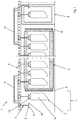
- FIG. 1 a device 1 for press hardening of components 2 is shown in longitudinal section.
- the device 1 has an oven 3, which is designed as a continuous furnace.
- Above the furnace 3 runs a transport device 4, which has means 5, on which the components 2 can be attached via receiving elements 6 hanging.
- the components 2 of a loading station 7, in which the means 5 are loaded with the components, through the oven 3 through to a pressing position in a press 8 can be transported without a further manipulation is required in between.
- the furnace 3 has for this purpose an entrance door 9 and on the exit side an exit door 10, which are each designed as sliding doors. About the front door 9 and the exit door 10, the oven 3 can be closed or opened to achieve a better heat distribution in the closed state and in particular to keep the heat losses low.
- the transport device 4 is formed as a kind of guide rail, in which the means 5 are guided.
- a first drive mechanism 11 is provided, which causes a slowed movement of the means 5 and thus simplifies the loading.
- the transport device 4 is assigned a second drive mechanism 12, which serves as an emergency discharge and bridges the distance to the press.
- the means 5 with the components 2 heated in the oven are thereby moved at a higher speed from the outlet of the furnace into the press 8. The time in which the components cool down 2 is thus kept low.
- the components 2 thus come with very little loss of temperature in the press 8 and can be converted directly there.
- the press 8 is formed in this embodiment as a horizontal press, so has a horizontal pressing direction, so that the hanging or vertically aligned components 2 can be pressed directly without having to be rotated or pivoted before. Rather, the components 2 can be easily brought to the means 5 hanging tamper-free in the press.
- connection regions 13 which lie outside a use region 14 of the components 2.
- connection regions 13 are formed in the shape of tabs on the use region 14.
- a coating which is present in the use region 14 does not come into contact with the receiving elements 6 of the means 5, so that more aggressive coatings which lead to corrosion on the means 5 or on the receiving elements 6 could be easily handled by the connection areas 13 can be carried out uncoated.
- the components 2 via two coupling points 15, 16 are held on the receiving elements 6 of the means 5.
- the coupling points 15, 16 are formed as protruding pins, which engage in eyelets, which are formed in the connection areas 13 of the components 2.
- the components 2 are thus held in a form-fitting manner by being pushed onto the pins of the coupling points 15, 16.
- a separate embodiment of the receiving elements 6 but is easily possible.
- the receiving elements 6 may also be designed as active grippers, so that lower demands are placed on the shape of the connecting regions 13 of the components 2.
- a separate embodiment of the connection regions can also be dispensed with.
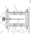
- FIG. 2 is a cross section through the furnace 3 and the transport device 4 is shown.
- the means 5 are movably guided via wheels 17 in the transport device 4 designed as a guide rail.
- the components 2 are attached via the receiving elements 6 hanging on the means 5 and thus to the transport device 4, so that the components 2 can be passed through the furnace 3 without contact with the use region 14 of the components 2.
- gas burners 20 are introduced, for example. By an appropriate number of gas burners 20 an optimal temperature distribution in the oven 3 can be achieved.
- the gas burners 20 serve, for example, for introducing heat energy into the furnace. In this case, 3 temperatures of up to 1200 ° C can be generated in the oven.
- the device 1 is shown with an additional, arranged between the oven 3 and press 8 tempering device 21.
- an active partial temperature control of the components ie an active heating or cooling of partial areas can take place.
- the tempering device 21 may, for example, infrared radiators to produce a local heating of the components 2 via radiant heat. Cooling can be carried out, for example, with the aid of air nozzles, which are formed in the temperature control device 21.
- an active tempering device 21 can also be provided to provide the means 5 with cover devices to partially cover the components 2 before transport through the furnace 3 and thus allow less heating in these areas. As a result, individual regions of the components 2 can be kept cooler.
- a ductility or a degree of hardness or a strength adjustment in individual areas of the finished components can be influenced.
- the invention is not limited to the exemplary embodiments shown, but can be modified in many ways.
- a design as a holding furnace is also conceivable in which the components are transported standing on the means.
- the components which are shown in the embodiment as simple sheets, may also have more complicated shapes and be formed, for example, as profiles or tubes or by a combination of several elements, which are welded together, for example.
- coated components in particular coated metal sheets
- the Transport device By dispensing with additional manipulators by the Transport device, the components transported continuously from a loading station through the oven to the press, cycle times, especially the time from the exit from the oven until the beginning of the pressing process, significantly reduced.
- the components are thus introduced by the same means in the oven, passed through the oven and transported in the press.
Landscapes
- Engineering & Computer Science (AREA)
- Chemical & Material Sciences (AREA)
- Mechanical Engineering (AREA)
- General Engineering & Computer Science (AREA)
- Crystallography & Structural Chemistry (AREA)
- Thermal Sciences (AREA)
- Physics & Mathematics (AREA)
- Materials Engineering (AREA)
- Metallurgy (AREA)
- Organic Chemistry (AREA)
- Tunnel Furnaces (AREA)
- Heat Treatments In General, Especially Conveying And Cooling (AREA)
- Heat Treatment Of Articles (AREA)
Claims (12)
- Dispositif de trempe sous presse de composants (2) avec au moins un four (3), une presse (8) montée en aval de l'au moins un four (3) et un dispositif de transport (4), dans lequel des moyens (5) sont logés de manière mobile pour le transport des composants (2) dans le dispositif de transport (4), caractérisé en ce que les moyens (5) sont mobiles avec les composants (2) le long du dispositif de transport (4) au travers du four (3) et dans la presse (8), dans lequel le dispositif de transport (4) est continu entre le four (3) et la presse (8) et dans lequel le transport des composants (2) du four (3) à la presse (8) peut être réalisé sans manipulation.
- Dispositif selon la revendication 1, caractérisé en ce que le dispositif de transport (4) est continu d'un poste de chargement (7) dans le sens de déplacement avant le four (3) au moins jusqu'à une position de pressage dans la presse (8).
- Dispositif selon la revendication 1 ou 2, caractérisé en ce que le four (3) est réalisé en tant que four continu.
- Dispositif selon l'une quelconque des revendications précédentes, caractérisé en ce que la presse (8) est réalisée en tant que presse avec un sens de pressage horizontal.
- Dispositif selon l'une quelconque des revendications précédentes, caractérisé en ce que le dispositif de transport (4) est guidé en dehors du four (3) et/ou de la presse (8).
- Dispositif selon l'une quelconque des revendications précédentes, caractérisé en ce que le dispositif de transport (4) est guidé dans le four (3) et/ou la presse (8).
- Dispositif selon l'une quelconque des revendications précédentes, caractérisé en ce que les moyens (5) présentent pour le transport des composants (2) des éléments de réception (6) sur lesquels les composants (2) peuvent être fixés par suspension.
- Dispositif selon l'une quelconque des revendications 1 à 6, caractérisé en ce que les moyens (5) présentent pour le transport des composants (2) des éléments de réception (6) sur lesquels les composants (2) peuvent être fixés verticalement.
- Dispositif selon l'une quelconque des revendications précédentes, caractérisé en ce que les moyens (5) présentent pour le transport des composants (2) des dispositifs de recouvrement avec lesquels les composants (2) peuvent être recouverts au moins partiellement.
- Dispositif selon l'une quelconque des revendications précédentes, caractérisé en ce qu'un dispositif d'équilibrage de température (21) est agencé dans le four (3) et/ou entre le four (3) et la presse (8) et/ou dans la presse (8) avec lequel des zones individuelles des composants (2) peuvent être tempérées activement.
- Dispositif selon l'une quelconque des revendications précédentes, caractérisé en ce que le dispositif de transport (4) est réalisé en tant que rail de guidage dans lequel les moyens (5) sont guidés pour le transport des composants (2).
- Procédé de trempe sous presse de composants en utilisant un dispositif selon l'une quelconque des revendications 1 à 11, comprenant les étapes suivantes :a) la fixation des composants (2) sur des moyens (5) pour le transport des composants (2), qui sont logés de manière mobile dans un dispositif de transport (4), et le transport des composants (2) le long du dispositif de transport (4) vers un four (3),b) l'introduction des composants (2) fixés sur les moyens (5) pour le transport des composants dans le four (3),c) le transport des composants (2) fixés sur les moyens (5) pour le transport des composants au travers du four (3) le long du dispositif de transport (4), dans lequel les composants (2) sont réchauffés,d) le transport continu des composants (2) fixés sur les moyens (5) pour le transport des composants le long du dispositif de transport (4) vers une presse (8),e) le formage des composants (2) dans la presse (8).
Applications Claiming Priority (2)
| Application Number | Priority Date | Filing Date | Title |
|---|---|---|---|
| DE102013104229.5A DE102013104229B3 (de) | 2013-04-25 | 2013-04-25 | Vorrichtung zum Presshärten von Bauteilen |
| PCT/EP2014/057359 WO2014173703A1 (fr) | 2013-04-25 | 2014-04-11 | Dispositif de trempe sous presse d'éléments structuraux |
Publications (2)
| Publication Number | Publication Date |
|---|---|
| EP2989220A1 EP2989220A1 (fr) | 2016-03-02 |
| EP2989220B1 true EP2989220B1 (fr) | 2018-10-10 |
Family
ID=50549286
Family Applications (1)
| Application Number | Title | Priority Date | Filing Date |
|---|---|---|---|
| EP14719251.2A Active EP2989220B1 (fr) | 2013-04-25 | 2014-04-11 | Dispositif de trempe sous presse d'éléments structuraux |
Country Status (5)
| Country | Link |
|---|---|
| US (1) | US10590500B2 (fr) |
| EP (1) | EP2989220B1 (fr) |
| DE (1) | DE102013104229B3 (fr) |
| ES (1) | ES2704436T3 (fr) |
| WO (1) | WO2014173703A1 (fr) |
Families Citing this family (14)
| Publication number | Priority date | Publication date | Assignee | Title |
|---|---|---|---|---|
| RU2648725C2 (ru) * | 2014-01-30 | 2018-03-28 | Ниппон Стил Энд Сумитомо Метал Корпорейшн | Способ нагрева стального листа и устройство нагрева стального листа |
| DE102015215179A1 (de) * | 2015-08-07 | 2017-02-09 | Schwartz Gmbh | Verfahren zur Wärmebehandlung und Wärmebehandlungsvorrichtung |
| PL3156506T3 (pl) * | 2015-10-15 | 2019-06-28 | Automation, Press And Tooling, A.P. & T Ab | Sposób częściowego ogrzewania promieniowaniem do wytwarzania części hartowanych w procesie tłoczenia i układ do takiego wytwarzania |
| ITUB20155822A1 (it) * | 2015-11-23 | 2017-05-23 | Sat Surface Aluminium Tech S P A | Impianto di trattamento superficiale di pezzi |
| DE102015122796A1 (de) * | 2015-12-23 | 2017-06-29 | Benteler Automobiltechnik Gmbh | Warmformlinie zur Herstellung warmumgeformter und pressgehärteter Stahlblechprodukte sowie Verfahren zu dessen Betreibung |
| EP3408420A1 (fr) * | 2016-01-25 | 2018-12-05 | Schwartz GmbH | Procede de traitement thermique d'un élément métallique |
| JP7112329B2 (ja) | 2016-01-25 | 2022-08-03 | シュヴァルツ ゲーエムベーハー | 金属を熱処理する方法及び装置 |
| DE112017002311T5 (de) * | 2016-05-04 | 2019-02-14 | Magna International Inc. | Warmform-Werkzeug mit Infrarot-Lichtquelle |
| WO2018115914A1 (fr) * | 2016-12-19 | 2018-06-28 | Arcelormittal | Procédé de fabrication de pièces en acier aluminié formées par pressage à chaud |
| JP6635326B2 (ja) * | 2017-09-29 | 2020-01-22 | 日立金属株式会社 | 熱間鍛造材の製造方法 |
| JP6631862B2 (ja) | 2017-09-29 | 2020-01-15 | 日立金属株式会社 | 熱間鍛造材の製造方法 |
| DE102018108602A1 (de) * | 2018-04-11 | 2019-10-17 | Eisenmann Se | Hochtemperaturofen mit einem Fördersystem |
| CN108555160B (zh) * | 2018-04-13 | 2020-11-24 | 武汉理工大学 | 应用于热冲压的适用于钢铝混线生产的热冲压挂式加热炉 |
| SE542025C2 (en) * | 2018-06-21 | 2020-02-11 | Gestamp Hardtech Ab | Process and apparatus for cooling hot components |
Citations (1)
| Publication number | Priority date | Publication date | Assignee | Title |
|---|---|---|---|---|
| WO2014053550A1 (fr) * | 2012-10-04 | 2014-04-10 | Ebner Industrieofenbau Gmbh | Dispositif de maniement |
Family Cites Families (7)
| Publication number | Priority date | Publication date | Assignee | Title |
|---|---|---|---|---|
| DE102005057742B3 (de) * | 2005-12-02 | 2007-06-14 | Voestalpine Automotive Holding Gmbh | Verfahren und Vorrichtung zum Aufheizen von Stahlbauteilen |
| DE102006054389B4 (de) | 2006-11-17 | 2014-08-07 | Voestalpine Metal Forming Gmbh | Verfahren zum gezielten Erzeugen einer definierten Härte und/oder einer definierten Festigkeit von pressgehärteten und/oder warmumgeformten und/oder direkt und/oder indirekt umgeformten Blechbauteilen |
| DE102008055980A1 (de) * | 2008-04-17 | 2009-10-29 | Schwartz, Eva | Verfahren und Durchlaufofen zum Erwärmen von Werkstücken |
| DE102009050879B3 (de) * | 2009-10-27 | 2011-09-01 | Itg Induktionsanlagen Gmbh | Verfahren und Vorrichtung zur Erwärmung von Platinen |
| DE102010010156A1 (de) * | 2010-03-04 | 2011-09-08 | Kirchhoff Automotive Deutschland Gmbh | Verfahren zur Herstellung eines Formteiles mit mindestens zwei Gefügebereichen unterschiedlicher Duktilität |
| DE102011053698C5 (de) * | 2011-09-16 | 2017-11-16 | Benteler Automobiltechnik Gmbh | Verfahren zur Herstellung von Struktur- und Chassisbauteilen durch Warmformen und Erwärmungsstation |
| DE102013105488A1 (de) * | 2013-05-28 | 2014-12-04 | Thyssenkrupp Steel Europe Ag | Transportvorrichtung für heiße, dünnwandige Stahlteile |
-
2013
- 2013-04-25 DE DE102013104229.5A patent/DE102013104229B3/de not_active Expired - Fee Related
-
2014
- 2014-04-11 ES ES14719251T patent/ES2704436T3/es active Active
- 2014-04-11 WO PCT/EP2014/057359 patent/WO2014173703A1/fr active Application Filing
- 2014-04-11 US US14/785,876 patent/US10590500B2/en active Active
- 2014-04-11 EP EP14719251.2A patent/EP2989220B1/fr active Active
Patent Citations (1)
| Publication number | Priority date | Publication date | Assignee | Title |
|---|---|---|---|---|
| WO2014053550A1 (fr) * | 2012-10-04 | 2014-04-10 | Ebner Industrieofenbau Gmbh | Dispositif de maniement |
Also Published As
| Publication number | Publication date |
|---|---|
| EP2989220A1 (fr) | 2016-03-02 |
| ES2704436T3 (es) | 2019-03-18 |
| US20160076116A1 (en) | 2016-03-17 |
| WO2014173703A1 (fr) | 2014-10-30 |
| US10590500B2 (en) | 2020-03-17 |
| DE102013104229B3 (de) | 2014-10-16 |
Similar Documents
| Publication | Publication Date | Title |
|---|---|---|
| EP2989220B1 (fr) | Dispositif de trempe sous presse d'éléments structuraux | |
| EP2497840B2 (fr) | Système de four pour le réchauffage partiel d'ébauches métalliques | |
| EP2993241B1 (fr) | Procede et presse pour fabriquer au moins en partie des composants de tole durcis | |
| EP2324938B1 (fr) | Procédé et installation de formage à chaud destinés à la fabrication d'une pièce usinée durcie et déformée à chaud | |
| EP3004403B1 (fr) | Dispositif de transport pour pièces brûlantes en acier et à paroi mince | |
| EP3184656B1 (fr) | Ligne moulée à chaud pour la fabrication de produits de tôle d'acier moulés à chaud et durcis à la presse et son procédé de fonctionnement | |
| DE202016104191U1 (de) | Wärmebehandlungsvorrichtung | |
| DE102009036512B3 (de) | Verfahren und Vorrichtung zum Herstellen von Parabellenkern und Parabelfedern für insbesondere Fahrzeugchassis, Fahrzeugaufbauten und dgl. | |
| DE102009060388A1 (de) | Mehrstufiges direktes Formhärten | |
| EP3408416B1 (fr) | Procédé de traitement thermique et dispositif de traitement thermique | |
| DE102016202766A1 (de) | Wärmebehandlungsverfahren und Wärmebehandlungsvorrichtung | |
| WO2016124309A1 (fr) | Procédé, ensemble four et installation pour le formage à chaud de pièces | |
| WO2017137259A1 (fr) | Procédé de traitement thermique et dispositif de traitement thermique | |
| DE102013002625B4 (de) | Greifervorrichtung für den Transport erwärmter Blechplatinen, sowie Verfahren zum Herstellen von warmumgeformten und/oder pressgehärteten Blechformteilen | |
| DE102017125473B3 (de) | Verfahren und Vorrichtung zur Herstellung von partiell gehärteten Stahlblechbauteilen | |
| WO2020011301A1 (fr) | Procédé et dispositif de thermoformage de produits semi-finis métalliques | |
| DE102016109095B4 (de) | Vorrichtung und Verfahren zum partiellen Härten von Stahlblechbauteilen | |
| EP3554974B1 (fr) | Dispositif destiné au transport d'au moins une pièce chauffée | |
| DE102010027439C5 (de) | Turmofen zum Erhitzen von härtbaren Blechplatinen | |
| DE102009019573A1 (de) | Ofen und Verfahren zum Erwärmen wenigstens eines Werkstückes | |
| DE102005033042B3 (de) | Verfahren zur Wärmebehandlung metallischer Werkstücke und Vorrichtung zur Durchführung | |
| EP3862710B1 (fr) | Four de chauffage partiel des composants métalliques | |
| EP3318647B1 (fr) | Ligne de fabrication d'une pièce thermodurcie en forme de tôle | |
| DE102010053980B4 (de) | Etagenofen | |
| DE102021133071A1 (de) | Umformvorrichtung und Verfahren zum Umformen eines Dünnglases |
Legal Events
| Date | Code | Title | Description |
|---|---|---|---|
| PUAI | Public reference made under article 153(3) epc to a published international application that has entered the european phase |
Free format text: ORIGINAL CODE: 0009012 |
|
| 17P | Request for examination filed |
Effective date: 20150825 |
|
| AK | Designated contracting states |
Kind code of ref document: A1 Designated state(s): AL AT BE BG CH CY CZ DE DK EE ES FI FR GB GR HR HU IE IS IT LI LT LU LV MC MK MT NL NO PL PT RO RS SE SI SK SM TR |
|
| AX | Request for extension of the european patent |
Extension state: BA ME |
|
| DAX | Request for extension of the european patent (deleted) | ||
| STAA | Information on the status of an ep patent application or granted ep patent |
Free format text: STATUS: EXAMINATION IS IN PROGRESS |
|
| 17Q | First examination report despatched |
Effective date: 20170327 |
|
| REG | Reference to a national code |
Ref country code: DE Ref legal event code: R079 Ref document number: 502014009708 Country of ref document: DE Free format text: PREVIOUS MAIN CLASS: C21D0009480000 Ipc: C21D0009000000 |
|
| RIC1 | Information provided on ipc code assigned before grant |
Ipc: F27B 9/20 20060101ALI20180316BHEP Ipc: B21D 22/20 20060101ALI20180316BHEP Ipc: F27D 3/00 20060101ALI20180316BHEP Ipc: F27B 9/24 20060101ALI20180316BHEP Ipc: C21D 1/18 20060101ALI20180316BHEP Ipc: C21D 1/673 20060101ALI20180316BHEP Ipc: F27D 3/12 20060101ALI20180316BHEP Ipc: C21D 9/00 20060101AFI20180316BHEP Ipc: B21D 22/02 20060101ALI20180316BHEP Ipc: F27B 9/28 20060101ALI20180316BHEP Ipc: C21D 9/48 20060101ALI20180316BHEP |
|
| GRAP | Despatch of communication of intention to grant a patent |
Free format text: ORIGINAL CODE: EPIDOSNIGR1 |
|
| STAA | Information on the status of an ep patent application or granted ep patent |
Free format text: STATUS: GRANT OF PATENT IS INTENDED |
|
| INTG | Intention to grant announced |
Effective date: 20180511 |
|
| GRAS | Grant fee paid |
Free format text: ORIGINAL CODE: EPIDOSNIGR3 |
|
| GRAA | (expected) grant |
Free format text: ORIGINAL CODE: 0009210 |
|
| STAA | Information on the status of an ep patent application or granted ep patent |
Free format text: STATUS: THE PATENT HAS BEEN GRANTED |
|
| AK | Designated contracting states |
Kind code of ref document: B1 Designated state(s): AL AT BE BG CH CY CZ DE DK EE ES FI FR GB GR HR HU IE IS IT LI LT LU LV MC MK MT NL NO PL PT RO RS SE SI SK SM TR |
|
| REG | Reference to a national code |
Ref country code: GB Ref legal event code: FG4D Free format text: NOT ENGLISH |
|
| REG | Reference to a national code |
Ref country code: CH Ref legal event code: EP Ref country code: AT Ref legal event code: REF Ref document number: 1051311 Country of ref document: AT Kind code of ref document: T Effective date: 20181015 |
|
| REG | Reference to a national code |
Ref country code: IE Ref legal event code: FG4D Free format text: LANGUAGE OF EP DOCUMENT: GERMAN |
|
| REG | Reference to a national code |
Ref country code: DE Ref legal event code: R096 Ref document number: 502014009708 Country of ref document: DE |
|
| REG | Reference to a national code |
Ref country code: NL Ref legal event code: MP Effective date: 20181010 |
|
| REG | Reference to a national code |
Ref country code: LT Ref legal event code: MG4D |
|
| REG | Reference to a national code |
Ref country code: ES Ref legal event code: FG2A Ref document number: 2704436 Country of ref document: ES Kind code of ref document: T3 Effective date: 20190318 |
|
| PG25 | Lapsed in a contracting state [announced via postgrant information from national office to epo] |
Ref country code: NL Free format text: LAPSE BECAUSE OF FAILURE TO SUBMIT A TRANSLATION OF THE DESCRIPTION OR TO PAY THE FEE WITHIN THE PRESCRIBED TIME-LIMIT Effective date: 20181010 |
|
| PG25 | Lapsed in a contracting state [announced via postgrant information from national office to epo] |
Ref country code: FI Free format text: LAPSE BECAUSE OF FAILURE TO SUBMIT A TRANSLATION OF THE DESCRIPTION OR TO PAY THE FEE WITHIN THE PRESCRIBED TIME-LIMIT Effective date: 20181010 Ref country code: BG Free format text: LAPSE BECAUSE OF FAILURE TO SUBMIT A TRANSLATION OF THE DESCRIPTION OR TO PAY THE FEE WITHIN THE PRESCRIBED TIME-LIMIT Effective date: 20190110 Ref country code: LV Free format text: LAPSE BECAUSE OF FAILURE TO SUBMIT A TRANSLATION OF THE DESCRIPTION OR TO PAY THE FEE WITHIN THE PRESCRIBED TIME-LIMIT Effective date: 20181010 Ref country code: HR Free format text: LAPSE BECAUSE OF FAILURE TO SUBMIT A TRANSLATION OF THE DESCRIPTION OR TO PAY THE FEE WITHIN THE PRESCRIBED TIME-LIMIT Effective date: 20181010 Ref country code: LT Free format text: LAPSE BECAUSE OF FAILURE TO SUBMIT A TRANSLATION OF THE DESCRIPTION OR TO PAY THE FEE WITHIN THE PRESCRIBED TIME-LIMIT Effective date: 20181010 Ref country code: PL Free format text: LAPSE BECAUSE OF FAILURE TO SUBMIT A TRANSLATION OF THE DESCRIPTION OR TO PAY THE FEE WITHIN THE PRESCRIBED TIME-LIMIT Effective date: 20181010 Ref country code: IS Free format text: LAPSE BECAUSE OF FAILURE TO SUBMIT A TRANSLATION OF THE DESCRIPTION OR TO PAY THE FEE WITHIN THE PRESCRIBED TIME-LIMIT Effective date: 20190210 Ref country code: NO Free format text: LAPSE BECAUSE OF FAILURE TO SUBMIT A TRANSLATION OF THE DESCRIPTION OR TO PAY THE FEE WITHIN THE PRESCRIBED TIME-LIMIT Effective date: 20190110 |
|
| PG25 | Lapsed in a contracting state [announced via postgrant information from national office to epo] |
Ref country code: PT Free format text: LAPSE BECAUSE OF FAILURE TO SUBMIT A TRANSLATION OF THE DESCRIPTION OR TO PAY THE FEE WITHIN THE PRESCRIBED TIME-LIMIT Effective date: 20190210 Ref country code: AL Free format text: LAPSE BECAUSE OF FAILURE TO SUBMIT A TRANSLATION OF THE DESCRIPTION OR TO PAY THE FEE WITHIN THE PRESCRIBED TIME-LIMIT Effective date: 20181010 Ref country code: GR Free format text: LAPSE BECAUSE OF FAILURE TO SUBMIT A TRANSLATION OF THE DESCRIPTION OR TO PAY THE FEE WITHIN THE PRESCRIBED TIME-LIMIT Effective date: 20190111 Ref country code: RS Free format text: LAPSE BECAUSE OF FAILURE TO SUBMIT A TRANSLATION OF THE DESCRIPTION OR TO PAY THE FEE WITHIN THE PRESCRIBED TIME-LIMIT Effective date: 20181010 Ref country code: SE Free format text: LAPSE BECAUSE OF FAILURE TO SUBMIT A TRANSLATION OF THE DESCRIPTION OR TO PAY THE FEE WITHIN THE PRESCRIBED TIME-LIMIT Effective date: 20181010 |
|
| REG | Reference to a national code |
Ref country code: DE Ref legal event code: R097 Ref document number: 502014009708 Country of ref document: DE |
|
| PG25 | Lapsed in a contracting state [announced via postgrant information from national office to epo] |
Ref country code: IT Free format text: LAPSE BECAUSE OF FAILURE TO SUBMIT A TRANSLATION OF THE DESCRIPTION OR TO PAY THE FEE WITHIN THE PRESCRIBED TIME-LIMIT Effective date: 20181010 Ref country code: DK Free format text: LAPSE BECAUSE OF FAILURE TO SUBMIT A TRANSLATION OF THE DESCRIPTION OR TO PAY THE FEE WITHIN THE PRESCRIBED TIME-LIMIT Effective date: 20181010 |
|
| PLBE | No opposition filed within time limit |
Free format text: ORIGINAL CODE: 0009261 |
|
| STAA | Information on the status of an ep patent application or granted ep patent |
Free format text: STATUS: NO OPPOSITION FILED WITHIN TIME LIMIT |
|
| PG25 | Lapsed in a contracting state [announced via postgrant information from national office to epo] |
Ref country code: EE Free format text: LAPSE BECAUSE OF FAILURE TO SUBMIT A TRANSLATION OF THE DESCRIPTION OR TO PAY THE FEE WITHIN THE PRESCRIBED TIME-LIMIT Effective date: 20181010 Ref country code: SM Free format text: LAPSE BECAUSE OF FAILURE TO SUBMIT A TRANSLATION OF THE DESCRIPTION OR TO PAY THE FEE WITHIN THE PRESCRIBED TIME-LIMIT Effective date: 20181010 Ref country code: SK Free format text: LAPSE BECAUSE OF FAILURE TO SUBMIT A TRANSLATION OF THE DESCRIPTION OR TO PAY THE FEE WITHIN THE PRESCRIBED TIME-LIMIT Effective date: 20181010 Ref country code: RO Free format text: LAPSE BECAUSE OF FAILURE TO SUBMIT A TRANSLATION OF THE DESCRIPTION OR TO PAY THE FEE WITHIN THE PRESCRIBED TIME-LIMIT Effective date: 20181010 |
|
| 26N | No opposition filed |
Effective date: 20190711 |
|
| PG25 | Lapsed in a contracting state [announced via postgrant information from national office to epo] |
Ref country code: SI Free format text: LAPSE BECAUSE OF FAILURE TO SUBMIT A TRANSLATION OF THE DESCRIPTION OR TO PAY THE FEE WITHIN THE PRESCRIBED TIME-LIMIT Effective date: 20181010 |
|
| REG | Reference to a national code |
Ref country code: CH Ref legal event code: PL |
|
| REG | Reference to a national code |
Ref country code: BE Ref legal event code: MM Effective date: 20190430 |
|
| GBPC | Gb: european patent ceased through non-payment of renewal fee |
Effective date: 20190411 |
|
| PG25 | Lapsed in a contracting state [announced via postgrant information from national office to epo] |
Ref country code: MC Free format text: LAPSE BECAUSE OF FAILURE TO SUBMIT A TRANSLATION OF THE DESCRIPTION OR TO PAY THE FEE WITHIN THE PRESCRIBED TIME-LIMIT Effective date: 20181010 Ref country code: LU Free format text: LAPSE BECAUSE OF NON-PAYMENT OF DUE FEES Effective date: 20190411 |
|
| PG25 | Lapsed in a contracting state [announced via postgrant information from national office to epo] |
Ref country code: GB Free format text: LAPSE BECAUSE OF NON-PAYMENT OF DUE FEES Effective date: 20190411 Ref country code: CH Free format text: LAPSE BECAUSE OF NON-PAYMENT OF DUE FEES Effective date: 20190430 Ref country code: LI Free format text: LAPSE BECAUSE OF NON-PAYMENT OF DUE FEES Effective date: 20190430 |
|
| PG25 | Lapsed in a contracting state [announced via postgrant information from national office to epo] |
Ref country code: FR Free format text: LAPSE BECAUSE OF NON-PAYMENT OF DUE FEES Effective date: 20190430 Ref country code: BE Free format text: LAPSE BECAUSE OF NON-PAYMENT OF DUE FEES Effective date: 20190430 |
|
| PG25 | Lapsed in a contracting state [announced via postgrant information from national office to epo] |
Ref country code: TR Free format text: LAPSE BECAUSE OF FAILURE TO SUBMIT A TRANSLATION OF THE DESCRIPTION OR TO PAY THE FEE WITHIN THE PRESCRIBED TIME-LIMIT Effective date: 20181010 |
|
| PG25 | Lapsed in a contracting state [announced via postgrant information from national office to epo] |
Ref country code: IE Free format text: LAPSE BECAUSE OF NON-PAYMENT OF DUE FEES Effective date: 20190411 |
|
| REG | Reference to a national code |
Ref country code: AT Ref legal event code: MM01 Ref document number: 1051311 Country of ref document: AT Kind code of ref document: T Effective date: 20190411 |
|
| PG25 | Lapsed in a contracting state [announced via postgrant information from national office to epo] |
Ref country code: AT Free format text: LAPSE BECAUSE OF NON-PAYMENT OF DUE FEES Effective date: 20190411 |
|
| PG25 | Lapsed in a contracting state [announced via postgrant information from national office to epo] |
Ref country code: CY Free format text: LAPSE BECAUSE OF FAILURE TO SUBMIT A TRANSLATION OF THE DESCRIPTION OR TO PAY THE FEE WITHIN THE PRESCRIBED TIME-LIMIT Effective date: 20181010 |
|
| PG25 | Lapsed in a contracting state [announced via postgrant information from national office to epo] |
Ref country code: MT Free format text: LAPSE BECAUSE OF FAILURE TO SUBMIT A TRANSLATION OF THE DESCRIPTION OR TO PAY THE FEE WITHIN THE PRESCRIBED TIME-LIMIT Effective date: 20181010 Ref country code: HU Free format text: LAPSE BECAUSE OF FAILURE TO SUBMIT A TRANSLATION OF THE DESCRIPTION OR TO PAY THE FEE WITHIN THE PRESCRIBED TIME-LIMIT; INVALID AB INITIO Effective date: 20140411 |
|
| PG25 | Lapsed in a contracting state [announced via postgrant information from national office to epo] |
Ref country code: MK Free format text: LAPSE BECAUSE OF FAILURE TO SUBMIT A TRANSLATION OF THE DESCRIPTION OR TO PAY THE FEE WITHIN THE PRESCRIBED TIME-LIMIT Effective date: 20181010 |
|
| PGFP | Annual fee paid to national office [announced via postgrant information from national office to epo] |
Ref country code: ES Payment date: 20230627 Year of fee payment: 10 Ref country code: DE Payment date: 20230430 Year of fee payment: 10 Ref country code: CZ Payment date: 20230406 Year of fee payment: 10 |