EP2988914B1 - Device and method for producing a structure from curable material by impression - Google Patents
Device and method for producing a structure from curable material by impression Download PDFInfo
- Publication number
- EP2988914B1 EP2988914B1 EP14716794.4A EP14716794A EP2988914B1 EP 2988914 B1 EP2988914 B1 EP 2988914B1 EP 14716794 A EP14716794 A EP 14716794A EP 2988914 B1 EP2988914 B1 EP 2988914B1
- Authority
- EP
- European Patent Office
- Prior art keywords
- curable material
- radiation
- molding
- molding tool
- channel
- Prior art date
- Legal status (The legal status is an assumption and is not a legal conclusion. Google has not performed a legal analysis and makes no representation as to the accuracy of the status listed.)
- Active
Links
Images


Classifications
-
- B—PERFORMING OPERATIONS; TRANSPORTING
- B29—WORKING OF PLASTICS; WORKING OF SUBSTANCES IN A PLASTIC STATE IN GENERAL
- B29C—SHAPING OR JOINING OF PLASTICS; SHAPING OF MATERIAL IN A PLASTIC STATE, NOT OTHERWISE PROVIDED FOR; AFTER-TREATMENT OF THE SHAPED PRODUCTS, e.g. REPAIRING
- B29C35/00—Heating, cooling or curing, e.g. crosslinking or vulcanising; Apparatus therefor
- B29C35/02—Heating or curing, e.g. crosslinking or vulcanizing during moulding, e.g. in a mould
- B29C35/08—Heating or curing, e.g. crosslinking or vulcanizing during moulding, e.g. in a mould by wave energy or particle radiation
- B29C35/0805—Heating or curing, e.g. crosslinking or vulcanizing during moulding, e.g. in a mould by wave energy or particle radiation using electromagnetic radiation
-
- B—PERFORMING OPERATIONS; TRANSPORTING
- B29—WORKING OF PLASTICS; WORKING OF SUBSTANCES IN A PLASTIC STATE IN GENERAL
- B29C—SHAPING OR JOINING OF PLASTICS; SHAPING OF MATERIAL IN A PLASTIC STATE, NOT OTHERWISE PROVIDED FOR; AFTER-TREATMENT OF THE SHAPED PRODUCTS, e.g. REPAIRING
- B29C35/00—Heating, cooling or curing, e.g. crosslinking or vulcanising; Apparatus therefor
- B29C35/02—Heating or curing, e.g. crosslinking or vulcanizing during moulding, e.g. in a mould
- B29C35/0288—Controlling heating or curing of polymers during moulding, e.g. by measuring temperatures or properties of the polymer and regulating the process
-
- B—PERFORMING OPERATIONS; TRANSPORTING
- B29—WORKING OF PLASTICS; WORKING OF SUBSTANCES IN A PLASTIC STATE IN GENERAL
- B29C—SHAPING OR JOINING OF PLASTICS; SHAPING OF MATERIAL IN A PLASTIC STATE, NOT OTHERWISE PROVIDED FOR; AFTER-TREATMENT OF THE SHAPED PRODUCTS, e.g. REPAIRING
- B29C37/00—Component parts, details, accessories or auxiliary operations, not covered by group B29C33/00 or B29C35/00
- B29C37/005—Compensating volume or shape change during moulding, in general
-
- B—PERFORMING OPERATIONS; TRANSPORTING
- B29—WORKING OF PLASTICS; WORKING OF SUBSTANCES IN A PLASTIC STATE IN GENERAL
- B29C—SHAPING OR JOINING OF PLASTICS; SHAPING OF MATERIAL IN A PLASTIC STATE, NOT OTHERWISE PROVIDED FOR; AFTER-TREATMENT OF THE SHAPED PRODUCTS, e.g. REPAIRING
- B29C43/00—Compression moulding, i.e. applying external pressure to flow the moulding material; Apparatus therefor
- B29C43/003—Compression moulding, i.e. applying external pressure to flow the moulding material; Apparatus therefor characterised by the choice of material
-
- B—PERFORMING OPERATIONS; TRANSPORTING
- B29—WORKING OF PLASTICS; WORKING OF SUBSTANCES IN A PLASTIC STATE IN GENERAL
- B29C—SHAPING OR JOINING OF PLASTICS; SHAPING OF MATERIAL IN A PLASTIC STATE, NOT OTHERWISE PROVIDED FOR; AFTER-TREATMENT OF THE SHAPED PRODUCTS, e.g. REPAIRING
- B29C43/00—Compression moulding, i.e. applying external pressure to flow the moulding material; Apparatus therefor
- B29C43/32—Component parts, details or accessories; Auxiliary operations
-
- B—PERFORMING OPERATIONS; TRANSPORTING
- B29—WORKING OF PLASTICS; WORKING OF SUBSTANCES IN A PLASTIC STATE IN GENERAL
- B29D—PRODUCING PARTICULAR ARTICLES FROM PLASTICS OR FROM SUBSTANCES IN A PLASTIC STATE
- B29D11/00—Producing optical elements, e.g. lenses or prisms
- B29D11/00009—Production of simple or compound lenses
- B29D11/00432—Auxiliary operations, e.g. machines for filling the moulds
- B29D11/00442—Curing the lens material
-
- G—PHYSICS
- G03—PHOTOGRAPHY; CINEMATOGRAPHY; ANALOGOUS TECHNIQUES USING WAVES OTHER THAN OPTICAL WAVES; ELECTROGRAPHY; HOLOGRAPHY
- G03F—PHOTOMECHANICAL PRODUCTION OF TEXTURED OR PATTERNED SURFACES, e.g. FOR PRINTING, FOR PROCESSING OF SEMICONDUCTOR DEVICES; MATERIALS THEREFOR; ORIGINALS THEREFOR; APPARATUS SPECIALLY ADAPTED THEREFOR
- G03F7/00—Photomechanical, e.g. photolithographic, production of textured or patterned surfaces, e.g. printing surfaces; Materials therefor, e.g. comprising photoresists; Apparatus specially adapted therefor
- G03F7/0002—Lithographic processes using patterning methods other than those involving the exposure to radiation, e.g. by stamping
-
- B—PERFORMING OPERATIONS; TRANSPORTING
- B29—WORKING OF PLASTICS; WORKING OF SUBSTANCES IN A PLASTIC STATE IN GENERAL
- B29C—SHAPING OR JOINING OF PLASTICS; SHAPING OF MATERIAL IN A PLASTIC STATE, NOT OTHERWISE PROVIDED FOR; AFTER-TREATMENT OF THE SHAPED PRODUCTS, e.g. REPAIRING
- B29C35/00—Heating, cooling or curing, e.g. crosslinking or vulcanising; Apparatus therefor
- B29C35/02—Heating or curing, e.g. crosslinking or vulcanizing during moulding, e.g. in a mould
- B29C35/08—Heating or curing, e.g. crosslinking or vulcanizing during moulding, e.g. in a mould by wave energy or particle radiation
- B29C35/0805—Heating or curing, e.g. crosslinking or vulcanizing during moulding, e.g. in a mould by wave energy or particle radiation using electromagnetic radiation
- B29C2035/0827—Heating or curing, e.g. crosslinking or vulcanizing during moulding, e.g. in a mould by wave energy or particle radiation using electromagnetic radiation using UV radiation
-
- B—PERFORMING OPERATIONS; TRANSPORTING
- B29—WORKING OF PLASTICS; WORKING OF SUBSTANCES IN A PLASTIC STATE IN GENERAL
- B29C—SHAPING OR JOINING OF PLASTICS; SHAPING OF MATERIAL IN A PLASTIC STATE, NOT OTHERWISE PROVIDED FOR; AFTER-TREATMENT OF THE SHAPED PRODUCTS, e.g. REPAIRING
- B29C43/00—Compression moulding, i.e. applying external pressure to flow the moulding material; Apparatus therefor
- B29C43/32—Component parts, details or accessories; Auxiliary operations
- B29C43/58—Measuring, controlling or regulating
- B29C2043/5891—Measuring, controlling or regulating using imaging devices, e.g. cameras
-
- B—PERFORMING OPERATIONS; TRANSPORTING
- B29—WORKING OF PLASTICS; WORKING OF SUBSTANCES IN A PLASTIC STATE IN GENERAL
- B29D—PRODUCING PARTICULAR ARTICLES FROM PLASTICS OR FROM SUBSTANCES IN A PLASTIC STATE
- B29D11/00—Producing optical elements, e.g. lenses or prisms
- B29D11/00009—Production of simple or compound lenses
- B29D11/00038—Production of contact lenses
- B29D11/00125—Auxiliary operations, e.g. removing oxygen from the mould, conveying moulds from a storage to the production line in an inert atmosphere
- B29D11/00134—Curing of the contact lens material
-
- B—PERFORMING OPERATIONS; TRANSPORTING
- B29—WORKING OF PLASTICS; WORKING OF SUBSTANCES IN A PLASTIC STATE IN GENERAL
- B29D—PRODUCING PARTICULAR ARTICLES FROM PLASTICS OR FROM SUBSTANCES IN A PLASTIC STATE
- B29D11/00—Producing optical elements, e.g. lenses or prisms
- B29D11/00009—Production of simple or compound lenses
- B29D11/00365—Production of microlenses
-
- B—PERFORMING OPERATIONS; TRANSPORTING
- B29—WORKING OF PLASTICS; WORKING OF SUBSTANCES IN A PLASTIC STATE IN GENERAL
- B29D—PRODUCING PARTICULAR ARTICLES FROM PLASTICS OR FROM SUBSTANCES IN A PLASTIC STATE
- B29D11/00—Producing optical elements, e.g. lenses or prisms
- B29D11/00009—Production of simple or compound lenses
- B29D11/0048—Moulds for lenses
-
- B—PERFORMING OPERATIONS; TRANSPORTING
- B29—WORKING OF PLASTICS; WORKING OF SUBSTANCES IN A PLASTIC STATE IN GENERAL
- B29K—INDEXING SCHEME ASSOCIATED WITH SUBCLASSES B29B, B29C OR B29D, RELATING TO MOULDING MATERIALS OR TO MATERIALS FOR MOULDS, REINFORCEMENTS, FILLERS OR PREFORMED PARTS, e.g. INSERTS
- B29K2101/00—Use of unspecified macromolecular compounds as moulding material
-
- B—PERFORMING OPERATIONS; TRANSPORTING
- B29—WORKING OF PLASTICS; WORKING OF SUBSTANCES IN A PLASTIC STATE IN GENERAL
- B29K—INDEXING SCHEME ASSOCIATED WITH SUBCLASSES B29B, B29C OR B29D, RELATING TO MOULDING MATERIALS OR TO MATERIALS FOR MOULDS, REINFORCEMENTS, FILLERS OR PREFORMED PARTS, e.g. INSERTS
- B29K2105/00—Condition, form or state of moulded material or of the material to be shaped
- B29K2105/24—Condition, form or state of moulded material or of the material to be shaped crosslinked or vulcanised
-
- G—PHYSICS
- G03—PHOTOGRAPHY; CINEMATOGRAPHY; ANALOGOUS TECHNIQUES USING WAVES OTHER THAN OPTICAL WAVES; ELECTROGRAPHY; HOLOGRAPHY
- G03F—PHOTOMECHANICAL PRODUCTION OF TEXTURED OR PATTERNED SURFACES, e.g. FOR PRINTING, FOR PROCESSING OF SEMICONDUCTOR DEVICES; MATERIALS THEREFOR; ORIGINALS THEREFOR; APPARATUS SPECIALLY ADAPTED THEREFOR
- G03F7/00—Photomechanical, e.g. photolithographic, production of textured or patterned surfaces, e.g. printing surfaces; Materials therefor, e.g. comprising photoresists; Apparatus specially adapted therefor
- G03F7/20—Exposure; Apparatus therefor
- G03F7/2002—Exposure; Apparatus therefor with visible light or UV light, through an original having an opaque pattern on a transparent support, e.g. film printing, projection printing; by reflection of visible or UV light from an original such as a printed image
-
- G—PHYSICS
- G03—PHOTOGRAPHY; CINEMATOGRAPHY; ANALOGOUS TECHNIQUES USING WAVES OTHER THAN OPTICAL WAVES; ELECTROGRAPHY; HOLOGRAPHY
- G03F—PHOTOMECHANICAL PRODUCTION OF TEXTURED OR PATTERNED SURFACES, e.g. FOR PRINTING, FOR PROCESSING OF SEMICONDUCTOR DEVICES; MATERIALS THEREFOR; ORIGINALS THEREFOR; APPARATUS SPECIALLY ADAPTED THEREFOR
- G03F7/00—Photomechanical, e.g. photolithographic, production of textured or patterned surfaces, e.g. printing surfaces; Materials therefor, e.g. comprising photoresists; Apparatus specially adapted therefor
- G03F7/20—Exposure; Apparatus therefor
- G03F7/2051—Exposure without an original mask, e.g. using a programmed deflection of a point source, by scanning, by drawing with a light beam, using an addressed light or corpuscular source
- G03F7/2059—Exposure without an original mask, e.g. using a programmed deflection of a point source, by scanning, by drawing with a light beam, using an addressed light or corpuscular source using a scanning corpuscular radiation beam, e.g. an electron beam
- G03F7/2065—Exposure without an original mask, e.g. using a programmed deflection of a point source, by scanning, by drawing with a light beam, using an addressed light or corpuscular source using a scanning corpuscular radiation beam, e.g. an electron beam using corpuscular radiation other than electron beams
-
- G—PHYSICS
- G03—PHOTOGRAPHY; CINEMATOGRAPHY; ANALOGOUS TECHNIQUES USING WAVES OTHER THAN OPTICAL WAVES; ELECTROGRAPHY; HOLOGRAPHY
- G03F—PHOTOMECHANICAL PRODUCTION OF TEXTURED OR PATTERNED SURFACES, e.g. FOR PRINTING, FOR PROCESSING OF SEMICONDUCTOR DEVICES; MATERIALS THEREFOR; ORIGINALS THEREFOR; APPARATUS SPECIALLY ADAPTED THEREFOR
- G03F7/00—Photomechanical, e.g. photolithographic, production of textured or patterned surfaces, e.g. printing surfaces; Materials therefor, e.g. comprising photoresists; Apparatus specially adapted therefor
- G03F7/70—Microphotolithographic exposure; Apparatus therefor
Definitions
- the present invention relates to the production of structures of curable material by molding and a method of curing the same by radiation.
- UV-curing plastics such as Ormocere, UV adhesives from Delo, Norland, Epoxy Technology or Panacol-Elosol, disappear during the irradiation in the range of a few percent of the volume. If the plastics are molded during a manufacturing process and then irradiated, shape deviations between the tool and the molded structure result, which can not be accepted especially in optical applications.
- the impression taking using UV-curable polymers takes place, inter alia, in two variants and therefore in two different types of devices.
- the method involves either the simultaneous impression of many structures, parallel to each other over a large area or the repeated molding of individual structures in a sequential process, wherein the individual impressions are carried out spatially next to each other on a common substrate.
- the first process variant is usually done in a mask aligner, which allows the exact positioning of the molding tool with respect to markings on the substrate to be molded on.
- the polymer present on the substrate is irradiated through the tool or through the substrate with UV radiation and thus cured.
- the second process variant is usually in a so-called step & repeat machine, the z. B. may be an adapted nanoimprint lithography device.
- the z. B. may be an adapted nanoimprint lithography device.
- a defined amount of polymer to be cured is deposited on a substrate so that a drop of polymer forms on the substrate.
- a mold is then attached to the drop positioned so that the drop on the one hand assumes the shape of the later structure and on the other can be positioned on the substrate with the molding tool.
- the curing of the polymer by UV radiation wherein the UV radiation, for example, by a transparently designed molding tool or through the substrate can cause curing of the polymer.
- the impression tool is removed and positioned on an intermediate further drop of polymer to form the next structure. In this way, all the structures to be formed are gradually applied to the substrate.
- Such a method allows any pattern of the individual structures of the molding tool on the substrate with a position accuracy of better than 1 micron.
- FIG. 11 A possible sequence of the individual process steps is in Fig. 11 shown.
- a locally varying irradiation is carried out in such a way that a variable aperture with variable aperture size allows a variable intensity of the curing radiation and a variable size of the curing zone produced, so that first cured a central region of the lens to be formed, there occurring material shrinkage compensated by nachf pollutiondes material can be and then the peripheral regions of the lens can be cured.
- the setting of the curing zone is done in this process by the shadow caused by the variable aperture.
- the curing of the polymer takes place by a temporal control of the transmission function of the illumination optical system comprising a radiation source and a variable diaphragm.
- a significant advantage is that not at the same time as other methods with a flood exposure over the entire wafer simultaneously, but by a variable in diameter aperture, such as a mechanical iris diaphragm or an LCD display.
- a variable in diameter aperture such as a mechanical iris diaphragm or an LCD display.
- EP 0 322 353 A2 is a concept for producing a plastic element by means of a mold comprising a cavity and a conveying channel communicating with the cavity described. It discloses a device according to the preamble of claim 1 and a method according to the preamble of claim 9.
- the object of the present invention is to provide a concept which enables a reduction of manufacturing scrap.
- the core idea of the present invention is to have recognized that the above object can be achieved if the hardening radiation is bundled by the arrangement of a beam-shaping optical element in an optical channel between the radiation source and the molding tool. This makes it possible to obtain a more accurate control of the curing of the curable polymer.
- two beam-shaping optical elements are arranged in an optical channel.
- a radiation cone propagating in the beam direction is formed by a first beam-shaping optical element into a beam of approximately constant width and focused in the further course of the beam by a second beam-shaping optical element, the intensity of the radiation increases in the direction of the molding tool.
- a beam-dividing element is arranged between the first and the second beam-shaping element, so that part of the radiation emitted by the radiation source can be coupled out and detected by a camera so as to enable observation of the radiation source.
- a beam splitting element decouples a portion of the radiation reflected from the direction of the forming tool and also directs it to a camera so as to allow observation of the curing zone.
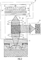
- Fig. 1 shows a device 10 with a molding tool 12, which comprises a molding surface 14 and is formed on a tool substrate 16. Laterally adjacent to the molding tool 12, membrane layers 18a and 18b are arranged on the tool substrate 16, which lie loosely against the tool substrate 16 in a channel region and terminate the channel region in a fluid-tight manner on the tool substrate. The fluid-tight sealed channel region thus forms channel structures 22a and 22b.
- the molding surface 14 may also include a coating to prevent the adhesion of molded materials to the molding tool 12.
- the molding tool 12 is positioned relative to a substrate 24 such that a region 26 is formed between a surface 25 of the substrate 24 and the molding tool 12, in which curable material 28 is arranged. Between the membrane structures 18a and 18b and the substrate is located adjacent to the region 26 further curable material 29, which is adapted to experience upon application of a pressure p 1 in the channel structures 22a and 22b a pressure.
- an irradiation unit 32 On the side facing away from the impression surface 14 of the molding tool 12, an irradiation unit 32 is arranged. It comprises a radiation source 34 which emits radiation 36. Radiation of radiation 36 is approximately parallel to each other at its origin. In a radiation direction, a gray filter 38 is arranged adjacent to and in the beam direction in front of a lens 42. The gray filter 38 is designed to attenuate a possibly excessive intensity of the radiation 36. In contrast, the diffuser 42 is formed to cancel collimation of the radiation 36 and to scatter the radiation 36.
- variable radiating surface 45 Adjacent to the diffuser 42 is a variable aperture 44 with a, formed by a variable opening diameter D1, variable radiating surface 45 is arranged.
- the variable radiating surface 45 is designed to allow a cone-shaped radiation 36b scattered by the diffusing screen 42 to emerge from the radiation source 34 with a cone width controlled by the variable opening diameter D1.
- an optical channel 46 is arranged which comprises a first beam-shaping optical element 48 and in a further course of the radiation direction a second beam-shaping optical element 52.
- the two beam-shaping optical elements 48 and 52 are designed such that they concentrate incident radiation.
- the first beam-shaping optical element 48 is designed and arranged such that the radiation 36b striking the first beam-shaping optical element 48 is collimated and the rays of the radiation 36b are approximately parallel to one another in the further course 36c. Due to the approximately parallel course of the rays in the radiation section 36c, the intensity of the radiation remains approximately constant over the course in the radiation direction.
- the radiation 36c is collimated by the second beam-shaping optical element 52 such that the intensity of the radiation increases in the section 36d by the bundling and in the region 26, in which the curable material 28 is arranged, neglecting absorption of the radiation by the curable material adjacent to the surface 25 has a local maximum.
- the local maximum of the intensity of the radiation 36 may, for example, also be positioned such that it is located between the impression surface 14 and the surface 25. In principle, the local maximum can be positioned at any axial location.
- Shrinkage of the curable material 28 induced by the radiation 36 may be compensated for by applying a pressure p 1 in the channel regions 22a and 22b such that the pressure p 1 in the channel structures 22a and 22b is at a pressure axially opposite to that in FIG Membrane structures 18a and 18b adjacent balancing areas with the other curable material 29 leads and a subsequent flow 54a-d of the further curable material 29 from the compensation area in the area 26 causes and closes by material shrinkage closes gaps.
- Compensation areas, in which the further curable material 29 is arranged are arranged such that the further curable material 29 undergoes no irradiation and thus remains uncured.
- the further curable material 29 can also be cured, for example by a complete opening of the diaphragm 44 or removed in a subsequent processing step, for example by a solvent.
- the two beam-shaping optical elements 48 and 52 By arranging the two beam-shaping optical elements 48 and 52, it is possible to adjust the radiation 36 entering the region 26 with great accuracy.
- the power of the radiation 36 can be controlled so accurately that the contour accuracy and thus the quality of molded lenses can be substantially increased.
- the diaphragm 44 is formed such that by adjusting the size of the radiating surface 45 of the variable diaphragm 44, the lateral extent of the area irradiated at one time is controllable, whereas the beam-shaping optical elements 48 and 52 are designed to control the degree of collimation of the radiation 36 and thus to allow a point with maximum radiation intensity.
- section 36c further optical elements for evaluating the radiation source and / or observing the curing zone may be arranged in region 26, as shown in the following exemplary embodiments.
- variable orifice 44 in combination with the beam-shaping optical elements 48 and 52, enables variable hardening of the curable material 28 along the surface 25 with precise adjustment of the curing zone by the beam-shaping optical elements 48 and 52.
- beam-forming optics expands the possibilities of controlling the curing process and allows a further improvement of the contour fidelity, since the polymer volume illuminated by the UV radiation and thus hardening can be optimally shaped in accordance with the achieved beam influence. It also allows the spatial separation of variable aperture and tool contour.
- tools and beam shaping optics are arranged side by side.
- sequential process control with a step & repeat machine, a single arrangement of tool and beam shaping optics is used.
- Fig. 1 1 shows an optical channel 46 with a two-lens path formed by the beam-shaping optical elements 48 and 52, which images the plane of the variable orifice 44 in the vicinity of the curing zone and thus in the vicinity of the substrate surface 25.
- Fig. 2 shows device 10 Fig. 1 in which a beam-splitting optical element in the form of a beam splitter cube 56 is arranged in the two-lobe beam path of the optical channel 46 and in the radiation direction between the first beam-shaping optical element 48 and the second beam-shaping optical element 52.
- the beam splitter cube 56 is configured to decouple a portion of the radiation 36c and arranged so that a decoupled portion 58 is directed onto an image surface of a camera 64.
- the camera 64 is designed to enable observation and evaluation of the emitted radiation 36.
- the evaluation may relate, for example, to the shape of the beam in section 36b or the degree of scattering of the radiation by the diffuser 42. It is also conceivable that the intensity of the radiation 36 can be monitored in this way.
- a differently shaped beam-splitting optical element such as a pelicle or a beam splitter plate, to decouple a portion of the radiation laterally from the beam splitting optical element 56 in the form of a beam splitter cube.
- Fig. 3 shows a device similar to device 10 in Fig. 2 in which the beam splitter cube 56 is arranged such that a portion of radiation reflected back from the molding tool or curing zone and the decoupled portion 58 'of the reflected radiation is directed onto the image surface of the camera 64' to allow observation of the curing zone.
- the beam splitting optical element 56 is shown as a beam splitter cube is analog Fig. 2
- Another conceivable embodiment of the beam-splitting element for example as a pelicle or as a beam splitter plate, conceivable.
- a monitoring and evaluation of the radiation source in combination with observation and evaluation of the curing zone a control or control circuit is constructed such that the radiation passing through the optical channel through the radiation source, the variable diaphragm or the beam-shaping optical elements is influenced, that the curing is optimized in a desired manner.
- an observed too rapid hardening can be compensated by a more strongly attenuating gray filter 38, so that the radiation intensity is reduced and thus the hardening is slowed down.
- Interventions in the curing process such as an adjustment of the radiation intensity can be done via an automated control or regulation, via the one Evaluation of the radiation source and / or the curing zone takes place.
- an observation and / or evaluation of the radiation source and / or the curing zone as well as the intervention in the curing process can be carried out manually by an operator.
- a camera for monitoring the curing zone or the radiation source is shown, other types of image sensors are possible, such as an intensity meter.
- Fig. 4 shows apparatus 10, wherein in the radiation direction between the first beam-shaping optical element 48 and the second beam-shaping optical element 52, a further variable aperture 66 is arranged.
- the further variable diaphragm 66 comprises an aperture 67 variable in size and lateral position with the variable diameter D2.
- variable diaphragm 66 is also designed to precisely adjust the lateral extent 68 in which the area 26 is irradiated by the radiation 36, since the irradiated area can be resolved laterally very precisely.
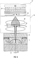
- Fig. 5 shows a device 10 analog Fig. 1 with a two-lens beam path in which microstructures 72 for locally adjusting the divergence of the illumination and diaphragm structures 74a and 74b for shielding areas 76a and 76b from irradiation are arranged on the substrate of the molding tool.
- Strongly directed irradiation of the curable material 28 may lead to the formation of refractive index gradients in the curable material 28, which may lead to streaking and hence deteriorated optical performance of the cured material.
- An avoidance of streaking can therefore be achieved by a diffuse irradiation.
- the use of the local microstructures 72 allows diffusion of incoming radiation and thus leads to locally increased divergence of the radiation, which avoids the formation of streaks.
- the transmitted light from the optics can be scattered locally and the directional effect of the upstream optics are partially or completely canceled.
- diffractive elements can also be arranged on the tool substrate for diffusion of the incoming radiation.
- These elements can be formed on one or both sides, continuously or discontinuously and can be arranged on one or more sides of the tool or of the tool substrate.
- the local diffusion elements may be disposed on the substrate to locally diverge radiation incident on the curable material through the substrate.
- the diaphragm structures 74a and 74b serve to shield regions 76a and 76b which are not intended to be cured during irradiation by the molding tool 12 or the tool substrate 16 or the membrane structures 18a, 18b.
- the aperture structures 74a and 74b shield the radiation 36 such that the channel-like shadows 76a and 76b are formed.
- the curable material 28 or further curable material 29 remains uncured during irradiation. After a curing or subsequent cleaning or development process, no cured material is disposed in these areas. These areas may then be used, for example, to enter a solvent or to dissolve soluble hardenable material to create air spaces.
- microstructures or diaphragm structures expands the field of application of beam-shaping devices in such a way that additional degrees of freedom with regard to the design as well as an increased quality of the molded structures can be achieved.
- Fig. 6a-c show schematic representations of a conversion of a variable aperture 44th
- a first aperture 78 having a plurality of apertures 79a-d is disposed opposite a second aperture 82 having a plurality of apertures 83a-d such that the apertures 79a-d and 83a-d comprise common optical axes 84a-d.
- the first aperture 78 and the second aperture 82 are identical.
- the first diaphragm 78 and the second diaphragm 82 form a common effective diaphragm 86.
- the effective diaphragm 86 comprises variable transmission regions 45a-d and the effective shadow regions 92a-e.
- FIG. 12 illustrates the effect on the effective aperture 86 when the first aperture 78 and the second aperture 82 are displaced from each other about the optical axes 84a-d.
- the aperture 78 becomes lateral to the optical axes 84a-d in one direction and the second aperture 82 also shifted laterally in an opposite direction, so arise opposite Fig. 6a reduced variable passage areas 45a-d and enlarged variable shadow areas 92a-e of the effective aperture 86, but the centers of the respective passage areas and thus the optical axes remain stationary.
- Fig. 6c shows that a displacement of the first aperture 78 and the second aperture 82 relative to each other in opposite directions laterally to the optical axes 84a-d can be performed so far that the entire area of the effective aperture 86 has the shadow area 92 and the variable passbands 45 a Have size of zero.
- the spacing of the apertures 79a-d and the apertures 83a-d, respectively, when producing a plurality or a field of structures, corresponds to the single or multiple of the distance of the structures or lenses to be produced.
- the apertures 79 and 83 can be z. B. have simple rectangular or round openings.
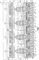
- Fig. 7 shows a device 20 comprising four impression tools 12a-d.
- the radiation source 34 is configured to provide the radiation 36.
- Adjacent to each curing region 26a-d, an optical channel 46a-d is arranged analogously to device 10.
- the variable aperture 44 has axially adjacent to the four optical channels 46a-d each have a variable radiating surface 45a-d.
- the variable gray filter 38 and the diffuser 42 are configured to filter and scatter the radiation 36 simultaneously for each of the four optical channels 46a-d.
- the diffuser 42 is configured to diffuse incident radiation 36 such that scattered radiation enters each of the four optical channels 46a-d.
- channel structures 22a-f are fluidly interconnected.
- the fluidic connection of the channel structures 22a-f results in that application of a pressure p 1 in one of the channel structures 22a-f also leads to formation of the pressure p 1 in the fluidically connected further channel structures.
- the impression tools 12a-d are arranged on the common tool substrate 16.
- the molding tools 12a-d are formed to mold the regions 26a-d on the substrate 24 with the surface 25.
- the impression tools are arranged on a common tool substrate and the regions 26a-d are molded on the surface of the common substrate, it is also possible for the tool substrate and / or the substrate to be formed from a plurality of individual components.
- hardened material 94a-e is arranged, which separates the areas 26a-d from each other such that further curable material 29 only in a laterally adjacent area 26a-d, but not in another compensation area can flow.
- the cured material 94a-e may be arranged such that between a step of disposing hardenable and further curable material 28 and 29 and irradiating the regions 26a-d, the further curable material may be in edge regions laterally spaced relative to the regions 26a-d the compensation areas, the further curable material 29 is cured.
- the formed axially to a plurality of optical channels and therefore large-area shaped radiation source 34 is formed so as to emit in the axially adjacent to the optical channels 46 a-d region of a collimated radiation.
- the diffusion plate 42 is formed to cancel out the collimation and to act respectively as a point radiation source with respect to the variable radiation surfaces 45a-d and the optical channels 46a-d subsequently arranged in the beam direction.
- an optical channel in each case comprises two beam-shaping optical elements, it is likewise conceivable for only one beam-shaping optical element or else a plurality of beam-shaping optical elements to be included in an optical channel.
- the beam-shaping optical elements 48 and 52 are represented as lenses in previous embodiments, it is also conceivable that the optical channel comprises one or more other beam-shaping optical elements, for example a prism, a diffractive structure or a Fresnel lens.
- the beam-shaping optical elements may be the same or different from each other, and optical channels may differ from each other in that different optical Channels comprise different beam-shaping optical elements.
- FIG. 12 shows a flowchart of a method 100 according to an embodiment of the present invention.
- the method 100 for producing a structure of curable material by molding comprises a first step 110 of arranging an impression tool 12 above a surface 25, for example a glass substrate, such that in a region 26 between the molding tool 12 and the surface 25 the curable material 28, For example, a UV polymer, on the surface 25 and the surface 25 facing molding surface 14 of the molding tool 12 adjacent and so that further curable material 29 can flow into the region 26.
- a UV polymer for example, on the surface 25 and the surface 25 facing molding surface 14 of the molding tool 12 adjacent and so that further curable material 29 can flow into the region 26.
- the method 100 comprises a second step 120 of the locally varying irradiation of the curable material 28 by means of a beam 36, which traverses an optical channel 46 arranged between a radiation source 34 and the molding tool 12 and beam collimating during the traversal, in the region, see FIG the hardenable material 28 laterally hardens at different rates along the surface 25 and shrinkages during hardening of the curable material 28 are compensated by the further curable material 29.
- a subsequent flow of the further curable material 29 into the region 26 can be induced, for example, by applying the pressure p 1 in the channel structures 22a and 22b and thus applying a pressure to the further curable material 29.
- the further curable material 29 is acted upon by a pressure from a lateral side in order to effect a subsequent flow of the further curable material 29 into the region 26. If the pressure p 1 is applied during the irradiation, then the further curable material 29 flows into the region 26 during the shrinkage.
- FIG. 9 shows a flowchart of a method 200 according to an embodiment of the present invention.
- the method 200 for producing a structure of curable material by molding comprises a first step 210 of arranging a molding tool 12 above a surface 25, for example a glass substrate, so that in a region 26 between the molding tool 12 and the surface 25 of the curable material 28 at the surface 25 and a surface facing the impression surface 14 of the molding tool 12 is adjacent and so that further curable material 29 can flow into the region 26.
- the method 200 comprises a second step 220 of locally varying irradiation of the curable material 28 by means of a beam 36 traversing an optical channel 46 disposed between the radiation source 34 and the molding tool 12 and beam-focused during traversal in the region such that the curable material 28 is lateral along the surface 25 cures at different rates, and shrinkages during curing of the curable material 28 are compensated by the further curable material 29, wherein the locally varying irradiation from one of the molding surface 14 opposite side of the molding tool 12 is performed through the molding tool 12 therethrough.
- an improvement of the curing process is, inter alia, an optimized production of micro-optical-electromechanical systems (MOEMS) by replication processes, such.
- MOEMS micro-optical-electromechanical systems
- optical elements are arranged per structure to be cured, which can be used to beam-shape the UV-curing UV radiation. Allow radiation.
- Fig. 10 shows a device for locally varying irradiation, according to the prior art.
- the device comprises the irradiation unit 32 and the molding tool 12, which is arranged on the tool substrate 16.
- the curable material 28 is arranged, wherein the mold opposite to the mold 12 facing surface 25 of the substrate 24 is arranged such that occurring during irradiation shrinkage in the curable material 28 by the Nachfie skill 54a and 54b of the further curable material 29 can be compensated.
- the optical channel 46 between the irradiation unit 32 and the substrate of the molding tool 16 does not comprise beam-shaping optical elements.
- the variable aperture 44 and the variable radiating surface 45 of diameter D1 are configured to confine the radiation 36 and thus allow for locally varying irradiation.
- this arrangement does not allow focusing of the radiation 36 in the curing zone or imaging of the radiation 36 or the curing zone in the region 26 onto a camera.
- the membrane structures 18a and 18b are arranged directly on the mold 12.
- the formation of the membrane structures 18a and 18b and the channel structures 22a and 22b and thus their function with respect to an application of external pressure to the further curable material 29 is identical.
- Fig. 11 shows an exemplary sequence of a sequential molding and curing process in a step & repeat machine
- the z. B. may be an adapted nanoimprint lithography device.
- a defined amount of polymer to be cured is deposited on the substrate so that a drop of polymer forms on the substrate.
- an impression tool is positioned on the drop, so that the drop firstly takes on the shape of the later lens and, on the other hand, can be positioned on the substrate with the molding tool.
- a step C the curing of the polymer by UV radiation, wherein the UV radiation, for example by a transparently designed molding tool or through the substrate can cause curing of the polymer.
- the impression tool is removed and positioned on an intermediate further drop of polymer to form the next lens. In this way, all lenses to be molded are gradually mounted on the substrate.
- the beam-splitting optical element can be arranged in the beam direction behind the at least first beam-shaping optical element.
- the beam-splitting optical element can be arranged in the beam direction in front of the at least first beam-shaping optical element.
- an aperture diaphragm which is variable in aperture size and / or lateral position can be arranged in a beam direction between the first and the second beam-shaping optical element.
- the locally varying irradiation may be carried out such that further curable material flows from a compensation area of the molding tool into the area which is not reached by a radiation with which the irradiation takes place.
Description
Die vorliegende Erfindung bezieht sich auf die Herstellung von Strukturen aus aushärtbarem Material durch Abformung und ein Verfahren zum Aushärten desselben durch eine Strahlung.The present invention relates to the production of structures of curable material by molding and a method of curing the same by radiation.
UV-härtende Kunststoffe, wie beispielsweise Ormocere, UV-Klebstoffe von Delo, Norland, Epoxy Technology oder Panacol-Elosol schwinden während der Bestrahlung im Bereich einiger Prozent des Volumens. Werden die Kunststoffe während eines Herstellungsprozesses abgeformt und anschließend bestrahlt, resultieren Formabweichungen zwischen Werkzeug und abgeformter Struktur, die speziell bei optischen Anwendungen nicht akzeptiert werden können.UV-curing plastics, such as Ormocere, UV adhesives from Delo, Norland, Epoxy Technology or Panacol-Elosol, disappear during the irradiation in the range of a few percent of the volume. If the plastics are molded during a manufacturing process and then irradiated, shape deviations between the tool and the molded structure result, which can not be accepted especially in optical applications.
Die Abformung unter Nutzung von UV-härtbaren Polymeren erfolgt unter anderem in zwei Varianten und dadurch bedingt in zwei verschiedenen Arten von Geräten. Das Verfahren beinhaltet entweder die Abformung vieler Strukturen zeitgleich, parallel miteinander auf großer Fläche oder die wiederholte Abformung einzelner Strukturen in einem sequenziellen Prozess, wobei die einzelnen Abformungen auf einem gemeinsamen Substrat räumlich nebeneinander ausgeführt werden.The impression taking using UV-curable polymers takes place, inter alia, in two variants and therefore in two different types of devices. The method involves either the simultaneous impression of many structures, parallel to each other over a large area or the repeated molding of individual structures in a sequential process, wherein the individual impressions are carried out spatially next to each other on a common substrate.
Die erste Prozessvariante erfolgt zumeist in einem Mask-Aligner, der die genaue Positionierung des Abformwerkzeuges bezüglich Markierungen auf dem Substrat, auf das abgeformt werden soll, ermöglicht. Zur Aushärtung wird das auf dem Substrat vorhandene Polymer durch das Werkzeug hindurch oder durch das Substrat hindurch mit UV-Strahlung bestrahlt und mithin ausgehärtet.The first process variant is usually done in a mask aligner, which allows the exact positioning of the molding tool with respect to markings on the substrate to be molded on. For curing, the polymer present on the substrate is irradiated through the tool or through the substrate with UV radiation and thus cured.
Ein mögliches Verfahren zur Bestrahlung durch das Werkzeug oder das Substrat hindurch ist aus
Die zweite Prozessvariante erfolgt zumeist in einer sogenannten Step & Repeat-Maschine, die z. B. ein adaptiertes Nano-Imprint-Lithografiegerät sein kann. Dabei wird auf einem Substrat eine definierte Menge auszuhärtendes Polymer abgelegt, so dass sich ein Tropfen Polymer auf dem Substrat bildet. Anschließen wird ein Abformwerkzeug auf den Tropfen positioniert, so dass der Tropfen zum einen die Form der späteren Struktur annimmt und zum anderen mit dem Abformwerkzeug auf dem Substrat positioniert werden kann.The second process variant is usually in a so-called step & repeat machine, the z. B. may be an adapted nanoimprint lithography device. In this case, a defined amount of polymer to be cured is deposited on a substrate so that a drop of polymer forms on the substrate. A mold is then attached to the drop positioned so that the drop on the one hand assumes the shape of the later structure and on the other can be positioned on the substrate with the molding tool.
Anschließend erfolgt die Aushärtung des Polymers durch UV-Strahlung, wobei die UV-Strahlung beispielsweise durch ein transparent ausgestaltetes Abformwerkzeug oder durch das Substrat hindurch eine Aushärtung des Polymers bewirken kann.Subsequently, the curing of the polymer by UV radiation, wherein the UV radiation, for example, by a transparently designed molding tool or through the substrate can cause curing of the polymer.
Nachdem das Polymer ausgehärtet ist, wird das Abformwerkzeug entfernt und auf einen zwischenzeitlich positionierten weiteren Tropfen Polymer positioniert, um die nächste Struktur auszuformen. Auf diese Art und Weise werden nach und nach alle abzuformenden Strukturen auf dem Substrat angebracht. Ein solches Verfahren erlaubt ein beliebiges Muster der Einzelstrukturen des Abformwerkzeuges auf dem Substrat mit einer Positionsgenauigkeit von besser 1 µm.After the polymer has cured, the impression tool is removed and positioned on an intermediate further drop of polymer to form the next structure. In this way, all the structures to be formed are gradually applied to the substrate. Such a method allows any pattern of the individual structures of the molding tool on the substrate with a position accuracy of better than 1 micron.
Ein möglicher Ablauf der einzelnen Prozessschritte ist in
Sowohl während des parallelen Prozesses als auch während des sequenziellen Prozesses führt Materialschwindung während der Aushärtung des Polymers dazu, dass die durch das Abformwerkzeug vorgegebene Form der optischen Struktur, beispielsweise der Linse, nicht exakt eingehalten werden kann und so Ungenauigkeiten in der Linse auftreten oder durch die Schwindung induzierte mechanische Spannungen zu einer Verformung des Substrats führen. In der
Die Festlegung der Aushärtezone erfolgt bei diesem Verfahren durch den von der variablen Blende verursachten Schattenwurf. Somit erfolgt die Aushärtung des Polymers durch eine zeitliche Steuerung der Transmissionsfunktion der eine Strahlungsquelle und eine variable Blende umfassenden Beleuchtungsoptik. Ein wesentlicher Vorteil liegt darin, dass die nicht wie bei anderen Verfahren mit einer Flutbelichtung über den gesamten Wafer gleichzeitig, sondern durch eine in ihrem Durchmesser variable Blende, wie beispielsweise eine mechanische Irisblende oder ein LCD-Display erfolgt. Trotz der größeren Konturtreue der so ausgebildeten Linsen, erlaubt dieser Prozess noch keine direkte Beobachtung des Prozessfortschrittes oder eine Beurteilung, ob ein aktiver Eingriff in den Prozess erforderlich ist. Eine weitere optische Justierung der härtenden Strahlung erfolgt in dem beschriebenen Prozess nicht.The setting of the curing zone is done in this process by the shadow caused by the variable aperture. Thus, the curing of the polymer takes place by a temporal control of the transmission function of the illumination optical system comprising a radiation source and a variable diaphragm. A significant advantage is that not at the same time as other methods with a flood exposure over the entire wafer simultaneously, but by a variable in diameter aperture, such as a mechanical iris diaphragm or an LCD display. Despite the greater contour accuracy of the lenses thus formed, this process still does not allow direct observation of the process progress or an assessment of whether active intervention in the process is required. A further optical adjustment of the curing radiation does not occur in the described process.
In
Wünschenswert wäre demnach ein Konzept, das eine kontrollierbare Aushärtung und Abformung und damit eine Reduktion von Herstellungsausschuss ermöglicht. Die Aufgabe der vorliegenden Erfindung besteht darin, ein Konzept zu schaffen, das eine Reduktion von Herstellungsausschuss ermöglicht.It would therefore be desirable to have a concept that allows controllable curing and molding and thus a reduction of production scrap. The object of the present invention is to provide a concept which enables a reduction of manufacturing scrap.
Diese Aufgabe wird durch eine Vorrichtung gemäß Anspruch 1 und ein Verfahren gemäß Anspruch 12 gelöst.This object is achieved by a device according to
Der Kerngedanke der vorliegenden Erfindung besteht darin, erkannt zu haben, dass obige Aufgabe gelöst werden kann, wenn die aushärtende Strahlung durch die Anordnung eines strahlformenden optischen Elementes in einem optischen Kanal zwischen Strahlungsquelle und Abformwerkzeug Strahlung gebündelt wird. Dadurch ist es möglich, eine genauere Steuerung der Aushärtung des aushärtbaren Polymers zu erhalten.The core idea of the present invention is to have recognized that the above object can be achieved if the hardening radiation is bundled by the arrangement of a beam-shaping optical element in an optical channel between the radiation source and the molding tool. This makes it possible to obtain a more accurate control of the curing of the curable polymer.
Gemäß einem Ausführungsbeispiel sind zwei strahlformende optische Elemente in einem optischen Kanal angeordnet. Dabei wird ein sich in Strahlrichtung verbreitender Strahlungskegel durch ein erstes strahlformendes optisches Element zu einem Strahl mit annähernd konstanter Breite geformt und im weiteren Verlauf des Strahls durch ein zweites strahlformendes optisches Element derart gebündelt, die Intensität der Strahlung in Richtung des Abformwerkzeuges steigt. Durch die Kombination einer in Aperturgröße und/oder lateralen Position der Apertur variablen Blende mit den strahlformenden Elementen kann die das Polymer aushärtende Strahlung exakt gesteuert und somit die Exaktheit der Kontur der Linse verbessert werden.According to one embodiment, two beam-shaping optical elements are arranged in an optical channel. In this case, a radiation cone propagating in the beam direction is formed by a first beam-shaping optical element into a beam of approximately constant width and focused in the further course of the beam by a second beam-shaping optical element, the intensity of the radiation increases in the direction of the molding tool. By combining a diaphragm which is variable in aperture size and / or lateral position of the aperture with the beam-shaping elements, the radiation curing the polymer can be precisely controlled and thus the accuracy of the contour of the lens can be improved.
Gemäß einem alternativen Ausführungsbeispiel ist zwischen dem ersten und dem zweiten strahlformenden Element ein strahlteilendes Element angeordnet, so dass ein Teil der von der Strahlungsquelle emittierenden Strahlung ausgekoppelt und von einer Kamera erfasst werden kann, um so eine Beobachtung der Strahlungsquelle zu ermöglichen.According to an alternative embodiment, a beam-dividing element is arranged between the first and the second beam-shaping element, so that part of the radiation emitted by the radiation source can be coupled out and detected by a camera so as to enable observation of the radiation source.
Gemäß einem weiteren Ausführungsbeispiel koppelt ein strahlteilendes Element einen Teil der aus der Richtung des Formwerkzeuges zurückgeworfenen Strahlung aus und lenkt diese ebenfalls auf eine Kamera, um so die Beobachtung der Aushärtezone zu ermöglichen.According to another embodiment, a beam splitting element decouples a portion of the radiation reflected from the direction of the forming tool and also directs it to a camera so as to allow observation of the curing zone.
Weitere vorteilhafte Ausführungsformen sind der Gegenstand der abhängigen Patentansprüche.Further advantageous embodiments are the subject of the dependent claims.
Bevorzugte Ausführungsbeispiele der vorliegenden Erfindung werden nachfolgend Bezug nehmend auf die beiliegenden Zeichnungen erläutert. Es zeigen:
- Fig. 1
- eine schematische Querschnittansicht einer Vorrichtung zum Aushärten aushärtbaren Materials mit einem optischen Kanal und stahlformenden Elementen;
- Fig. 2
- eine schematische Querschnittansicht einer Vorrichtung mit einem optischen Kanal, strahlformenden optischen Elementen und einem strahlteilenden optischen Element und einer Kamera;
- Fig. 3
- eine schematische Querschnittansicht einer Vorrichtung mit einem alternativen strahlteilenden optischen Element;
- Fig. 4
- eine schematische Querschnittansicht einer Vorrichtung, bei der der optische Kanal eine variable Blende umfasst;
- Fig. 5
- eine schematische Querschnittansicht einer Vorrichtung, bei der an dem Werkzeugsubstrat Blendenstrukturen und optische Mikrostrukturen angeordnet sind;
- Fig. 6a-c
- eine schematische Darstellung einer variablen Blende;
- Fig. 7
- eine schematische Querschnittansicht einer Vorrichtung zum lokal variierenden Bestrahlen mittels einer variablen Blende und mehrerer nebeneinander angeordneter Abformwerkzeuge;
- Fig. 8
- ein Flussdiagramm eines Verfahrens zum Herstellen einer Struktur aus aushärtbarem Material;
- Fig. 9
- ein Flussdiagramm eines alternativen Verfahrens zum Herstellen einer Struktur aus aushärtbarem Material;
- Fig. 10
- eine schematische Querschnittansicht einer Vorrichtung zum Herstellen einer Struktur aus aushärtbarem Material;
- Fig. 11
- eine Darstellung eines Abform- und Aushärteprozesses mit einer Step & Repeat-Maschine.
- Fig. 1
- a schematic cross-sectional view of an apparatus for curing hardenable material with an optical channel and steel-forming elements;
- Fig. 2
- a schematic cross-sectional view of an apparatus having an optical channel, beam-forming optical elements and a beam splitting optical element and a camera;
- Fig. 3
- a schematic cross-sectional view of a device with an alternative beam splitting optical element;
- Fig. 4
- a schematic cross-sectional view of an apparatus in which the optical channel comprises a variable aperture;
- Fig. 5
- a schematic cross-sectional view of an apparatus in which on the tool substrate diaphragm structures and optical microstructures are arranged;
- Fig. 6a-c
- a schematic representation of a variable aperture;
- Fig. 7
- a schematic cross-sectional view of a device for locally varying irradiation by means of a variable diaphragm and a plurality of juxtaposed impression tools;
- Fig. 8
- a flowchart of a method for producing a structure of hardenable material;
- Fig. 9
- a flowchart of an alternative method for producing a structure of hardenable material;
- Fig. 10
- a schematic cross-sectional view of an apparatus for producing a structure of hardenable material;
- Fig. 11
- a representation of a molding and curing process with a step & repeat machine.
Das Abformwerkzeug 12 ist gegenüber einem Substrat 24 derart positioniert, dass sich zwischen einer Oberfläche 25 des Substrats 24 und dem Abformwerkzeug 12 ein Bereich 26 ausbildet, in welchem aushärtbares Material 28 angeordnet ist. Zwischen den Membranstrukturen 18a und 18b und dem Substrat befindet sich angrenzend an den Bereich 26 weiteres aushärtbares Material 29, das ausgebildet ist, um bei Anlegen eines Drucks p1 in den Kanalstrukturen 22a und 22b einen Druck zu erfahren.The
An der der Abformfläche 14 abgewandten Seite des Abformwerkzeuges 12 ist eine Bestrahlungseinheit 32 angeordnet. Sie umfasst eine Strahlungsquelle 34, die eine Strahlung 36 emittiert. Strahlen der Strahlung 36 verlaufen an ihrem Ursprung annähernd parallel zueinander. In einer Strahlungsrichtung ist ein Graufilter 38 benachbart zu und in Strahlrichtung vor einer Streuscheibe 42 angeordnet. Das Graufilter 38 ist ausgebildet, um eine eventuell zu große Intensität der Strahlung 36 abzumildern. Dahingegen ist die Streuscheibe 42 ausgebildet, um eine Kollimation der Strahlung 36 aufzuheben und die Strahlung 36 zu streuen.On the side facing away from the
Benachbart zur Streuscheibe 42 ist eine variable Blende 44 mit einer, durch einen variablen Öffnungsdurchmesser D1 ausgebildeten, variablen Abstrahlfläche 45 angeordnet. Die variable Abstrahlfläche 45 ist ausgebildet, eine durch die Streuscheibe 42 gestreute, kegelförmige Strahlung 36b mit einer, durch den variablen Öffnungsdurchmesser D1 gesteuerten, Kegelbreite aus der Strahlungsquelle 34 austreten zu lassen. Zwischen der variablen Blende 44 und dem Werkzeugsubstrat 16 ist ein optischer Kanal 46 angeordnet, der ein erstes strahlformendes optisches Element 48 und in einem weiteren Verlauf der Strahlungsrichtung ein zweites strahlformendes optisches Element 52 umfasst.Adjacent to the
Die beiden strahlformenden optischen Elemente 48 und 52 sind dabei derart ausgebildet, dass sie einfallende Strahlung bündeln.The two beam-shaping
Dabei ist das erste strahlformende optische Element 48 derart ausgebildet und angeordnet, dass die auf das erste strahlformende optische Element 48 treffende Strahlung 36b kollimiert wird und die Strahlen der Strahlung 36b im weiteren Verlauf 36c annähernd parallel zueinander liegen. Durch den annähernd parallelen Verlauf der Strahlen im Strahlungsabschnitt 36c bleibt die Intensität der Strahlung über den Verlauf in Strahlungsrichtung annähernd konstant.In this case, the first beam-shaping
In Strahlrichtung wird die Strahlung 36c durch das zweite strahlformende optische Element 52 derart gebündelt, dass die Intensität der Strahlung im Abschnitt 36d durch die Bündelung steigt und im Bereich 26, in dem das aushärtbare Material 28 angeordnet ist, unter Vernachlässigung einer Absorption der Strahlung durch das aushärtbare Material benachbart zur Oberfläche 25 ein lokales Maximum aufweist.In the beam direction, the
Alternativ kann das lokale Maximum der Intensität der Strahlung 36 beispielsweise auch derart positioniert sein, dass es sich zwischen der Abformfläche 14 und der Oberfläche 25 befindet. Prinzipiell kann das lokale Maximum an einer beliebigen axialen Stelle positioniert sein.Alternatively, the local maximum of the intensity of the
Eine Schwindung des aushärtbaren Materials 28, der durch die Strahlung 36 ausgelöst wird, kann durch Anlegen eines Druckes p1 in den Kanalbereichen 22a und 22b derart kompensiert werden, dass der Druck p1 in den Kanalstrukturen 22a und 22b zu einem Druck in axial zu den Membranstrukturen 18a und 18b benachbarten Ausgleichsbereichen mit dem weiteren aushärtbarem Material 29 führt und ein Nachfließen 54a-d des weiteren aushärtbaren Materials 29 aus dem Ausgleichsbereich in den Bereich 26 bewirkt und durch Materialschwindung auftretende Lücken schließt. Ausgleichsbereiche, in denen das weitere aushärtbare Material 29 angeordnet ist, sind derart angeordnet, dass das weitere aushärtbare Material 29 keine Bestrahlung erfährt und mithin unausgehärtet bleibt. Hierfür wird entweder die Strahlung 36 am weiteren aushärtbaren Material 29 vorbei gelenkt oder das weitere aushärtbare Material 29 wird vor der Strahlung 36, beispielsweise durch eine Blende, abgeschirmt. Die axial zu den Membranstrukturen 18a und 18b benachbarten Ausgleichsbereiche sind dabei kein Teil optischer Funktionsbereiche der auszuhärtenden Struktur. Nach einer erfolgten Bestrahlung der auszuhärtenden Struktur kann das weitere aushärtbare Material 29 beispielsweise durch ein vollständiges Öffnen der Blende 44 ebenfalls ausgehärtet oder in einem nachfolgendem Bearbeitungsschritt entfernt werden, beispielsweise durch ein Lösungsmittel.Shrinkage of the
Durch die Anordnung der beiden strahlformenden optischen Elemente 48 und 52 ist es möglich, die in den Bereich 26 eintretende Strahlung 36 mit großer Exaktheit zu justieren. In Kombination mit der variablen Blende 44 kann die Leistung der Strahlung 36 derart genau gesteuert werden, dass die Konturtreue und mithin die Qualität abgeformter Linsen wesentlich gesteigert werden kann. Dabei ist die Blende 44 ausgebildet, dass durch die Justierung der Größe Abstrahlfläche 45 der variablen Blende 44 die laterale Ausdehnung des zu einem Zeitpunkt bestrahlten Bereichs steuerbar ist, wohingegen die strahlformenden optischen Elemente 48 und 52 ausgebildet sind, die Steuerung des Grades der Bündelung der Strahlung 36 und mithin eines Punktes mit maximaler Strahlungsintensität zu ermöglichen.By arranging the two beam-shaping
Im Abschnitt 36c können weitere optische Elemente zur Beurteilung der Strahlungsquelle und/oder zum Beobachten der Aushärtezone im Bereich 26 angeordnet sein, wie nachfolgende Ausführungsbeispiele zeigen.In
Die variable Blende 44 in Kombination mit den strahlformenden optischen Elementen 48 und 52 ermöglichen eine variable Aushärtung des aushärtbaren Materials 28 entlang der Oberfläche 25 mit einer exakten Justierung der Aushärtezone durch die strahlformenden optischen Elemente 48 und 52.The
Die Nutzung strahlformender Optiken erweitert die Möglichkeiten der Steuerung des Aushärteprozesses und ermöglicht eine weitere Verbesserung der Konturtreue, da das von der UV-Strahlung beleuchtete und mithin aushärtende Polymervolumen entsprechend der erzielten Strahlbeeinflussung optimal geformt werden kann. Es gestattet weiterhin die räumliche Trennung von variabler Blende und Werkzeugkontur. Im Fall der Prozeßführung mit einer Abformung vieler Strukturen zeitgleich und parallel nebeneinander durch einen Mask-Aligner sind viele gleichartige Strukturen, Werkzeuge und Strahlformungsoptiken nebeneinander angeordnet. Im Falle der sequenziellen Prozeßführung mit einer Step & Repeat-Maschine wird eine Einzelanordnung von Werkzeug und Strahlformungsoptik genutzt.The use of beam-forming optics expands the possibilities of controlling the curing process and allows a further improvement of the contour fidelity, since the polymer volume illuminated by the UV radiation and thus hardening can be optimally shaped in accordance with the achieved beam influence. It also allows the spatial separation of variable aperture and tool contour. In the case of process control with an impression of many structures simultaneously and parallel next to each other by a mask aligner many similar structures, tools and beam shaping optics are arranged side by side. In the case of sequential process control with a step & repeat machine, a single arrangement of tool and beam shaping optics is used.
Der Strahlteilerwürfel 56 ist ausgebildet, um einen Teil der Strahlung 36c auszukoppeln und so angeordnet, dass ein ausgekoppelter Anteil 58 auf eine Bildfläche einer Kamera 64 gelenkt wird. Die Kamera 64 ist ausgebildet, um eine Beobachtung und Auswertung der emittierten Strahlung 36 zu ermöglichen. Die Auswertung kann beispielsweise die Form des Strahls im Abschnitt 36b oder den Grad der Streuung der Strahlung durch die Streuscheibe 42 betreffen. Auch ist denkbar, dass die Intensität der Strahlung 36 auf diese Art und Weise überwacht werden kann.The
Obwohl in
Obwohl in
Werden die Ausführungsbeispiele der
Dies kann dabei in einem laufenden Prozess erfolgen, so dass Materialausschüsse durch eventuelle Fehlproduktionen vermindert werden können.This can be done in an ongoing process, so that material committees can be reduced by any defective production.
Obwohl in
Die variable Blende 66 ist zudem ausgebildet, die laterale Ausdehnung 68, in welcher der Bereich 26 von der Strahlung 36 bestrahlt wird, präzise zu justieren, da der bestrahlte Bereich lateral sehr präzise aufgelöst werden kann.The
Es ist denkbar, dass die in
Eine stark gerichtete Bestrahlung des aushärtbaren Materials 28 kann zur Bildung von Brechzahlgradienten im aushärtbaren Material 28 führen, was zu Schlieren und mithin verschlechterter optischer Funktion des ausgehärteten Materials führen kann. Eine Vermeidung der Schlierenbildung kann daher durch eine diffuse Bestrahlung erreicht werden. Die Nutzung der lokalen Mikrostrukturen 72 ermöglicht die Diffusion eintreffender Strahlung und führt damit zur lokal erhöhter Divergenz der Strahlung, was die Ausbildung von Schlieren vermeidet. Das von der Optik transmittierte Licht kann so lokal gestreut und die Richtungswirkung der vorgeschalteten Optik teilweise oder gänzlich aufgehoben werden.Strongly directed irradiation of the
Anstelle der gezeigten Mikrolinsen 72 können zur Diffusion der eintretenden Strahlung auch diffraktive Elemente, Oberflächen- oder Volumendiffusoren am Werkzeugsubstrat angeordnet sein. Diese Elemente können ebenso wie die Mikrolinsen ein- oder beidseitig, durchgängig oder diskontinuierlich ausgebildet sein und auf einer oder mehreren Seiten des Werkzeuges oder des Werkzeugsubstrates angeordnet sein. Auch können die Elemente zur lokalen Diffusion am Substrat angeordnet sein, um Strahlung, die durch das Substrat hindurch auf das aushärtbare Material trifft, lokal zu divergieren.Instead of the microlenses 72 shown, diffractive elements, surface or volume diffusers can also be arranged on the tool substrate for diffusion of the incoming radiation. These elements, like the microlenses, can be formed on one or both sides, continuously or discontinuously and can be arranged on one or more sides of the tool or of the tool substrate. Also, the local diffusion elements may be disposed on the substrate to locally diverge radiation incident on the curable material through the substrate.
Die Blendenstrukturen 74a und 74b dienen zur Abschirmung von Bereichen 76a und 76b, welche während einer Bestrahlung durch das Abformwerkzeug 12 respektive des Werkzeugsubstrates 16 oder die Membranstrukturen 18a, 18b hindurch nicht ausgehärtet werden sollen. Die Blendenstrukturen 74a und 74b schirmen die Strahlung 36 derart ab, dass die kanalartigen Schatten 76a und 76b ausgebildet werden. In den Bereichen der Schatten 76a und 76b bleibt das aushärtbare Material 28 oder das weitere aushärtbare Material 29 während einer Bestrahlung unausgehärtet. Nach einem, der Aushärtung folgendem, Reinigungs- oder Entwicklungsvorgang ist in diesen Bereichen kein ausgehärtetes Material angeordnet. Diese Bereiche können dann beispielsweise zum Eingeben eines Lösungsmittels oder zum Lösen von löslichem aushärtbaren Material, um Lufträume zu erzeugen, genutzt werden.The
Die Anordnung von Mikrostrukturen oder Blendenstrukturen erweitert den Anwendungsbereich strahlformender Vorrichtungen dahin gehend, dass zusätzliche Freiheitsgrade bezüglich der Ausgestaltung sowie eine erhöhte Qualität der abgeformten Strukturen erzielbar sind.The arrangement of microstructures or diaphragm structures expands the field of application of beam-shaping devices in such a way that additional degrees of freedom with regard to the design as well as an increased quality of the molded structures can be achieved.
Die
Die effektive Blende 86 umfasst dabei variablen Durchlassbereiche 45a-d und die effektiven Schattenbereiche 92a-e.The
Der Abstand der Aperturen 79a-d respektive der Aperturen 83a-d entspricht bei Herstellung einer Mehrzahl bzw. eines Feldes von Strukturen dem Einfachen oder Mehrfachen des Abstandes der herzustellenden Strukturen bzw. Linsen. Die Aperturen 79 und 83 können dabei z. B. einfache rechteckige oder runde Öffnungen aufweisen.The spacing of the
Die am Werkzeugsubstrat 16 angeordneten Kanalstrukturen 22a-f sind untereinander fluidisch verbunden. Die fluidische Verbindung der Kanalstrukturen 22a-f führt dazu, dass ein Anlegen eines Druckes p1 in einer der Kanalstrukturen 22a-f auch zu einer Ausbildung des Druckes p1 in den fluidisch verbundenen weiteren Kanalstrukturen führt.The arranged on the
Die Abformwerkzeuge 12a-d sind an dem gemeinsamen Werkzeugsubstrat 16 angeordnet. Dahingegen sind die Abformwerkzeuge 12a-d ausgebildet, um die Bereiche 26a-d auf dem Substrat 24 mit der Oberfläche 25 abzuformen.The
Obwohl in
Lateral benachbart zu den sowie zwischen je zwei Ausgleichsbereichen, in denen das weitere aushärtbare Material 29 angeordnet ist, ist ausgehärtetes Material 94a-e angeordnet, welches die Bereiche 26a-d derart von einander separiert, dass weiteres aushärtbares Material 29 lediglich in einen lateral benachbarten Bereich 26a-d, nicht jedoch in einen anderen Ausgleichsbereich fließen kann. Das ausgehärtete Material 94a-e kann beispielsweise derart angeordnet werden, dass zwischen einem Schritt eines Anordnens von aushärtbarem und weiterem aushärtbarem Material 28 und 29 und eines Bestrahlens der Bereiche 26a-d das weitere aushärtbare Material in bezüglich der Bereiche 26a-d lateral außen liegenden Randbereichen der Ausgleichsbereiche das weitere aushärtbare Material 29 ausgehärtet wird.Laterally adjacent to and between each two compensation areas in which the further
Die axial zu mehreren optischen Kanälen angeordnete und deswegen großflächige ausgeformte Strahlungsquelle 34 ist derart ausgebildet, um im axial zu den optischen Kanälen 46a-d benachbarten Bereich eine kollimierte Strahlung zu emittieren. Die Streuscheibe 42 ist dahingegen ausgebildet, um die Kollimation aufzuheben und bezüglich der variablen Abstrahlflächen 45a-d und der in Strahlrichtung nachfolgend angeordneten optischen Kanäle 46a-d jeweils wie eine punktförmige Strahlungsquelle zu wirken.The formed axially to a plurality of optical channels and therefore large-area shaped
Obwohl in vorangegangenen Ausführungsbeispielen ein optischer Kanal jeweils zwei strahlformende optische Elemente umfasst, ist es ebenfalls denkbar, dass lediglich ein strahlformendes optisches Element oder aber mehrere strahlformende optische Elemente von einem optischen Kanal umfasst werden.Although in previous exemplary embodiments an optical channel in each case comprises two beam-shaping optical elements, it is likewise conceivable for only one beam-shaping optical element or else a plurality of beam-shaping optical elements to be included in an optical channel.
Obwohl die strahlformenden optischen Elemente 48 und 52 in vorangegangenen Ausführungsbeispielen als Linse dargestellt werden, ist es ebenfalls denkbar, dass optischer Kanal ein oder mehrere andere strahlformenden optischen Elemente umfasst, beispielsweise ein Prisma, eine diffraktive Struktur oder eine Fresnel-Linse. Die strahl formenden optischen Elemente können gleich oder verschieden von einander ausgebildet sein, auch können optische Kanäle von einander sich dahingehend unterscheiden, dass unterschiedliche optische Kanäle unterschiedliche strahlformende optische Elemente umfassen. Weiterhin ist denkbar, dass im Falle einer Ausführung analog
Ein Nachfließen des weiteren aushärtbaren Materials 29 in den Bereich 26 kann dabei beispielsweise durch Aufbringen des Druckes p1 in den Kanalstrukturen 22a und 22b und mithin dem Aufbringen eines Druckes an dem weiteren aushärtbaren Material 29 induziert werden. Alternativ oder zusätzlich ist denkbar, dass das weitere aushärtbare Material 29 von einer lateralen Seite aus mit einem Druck beaufschlagt wird, um ein Nachfließen des weiteren aushärtbaren Materials 29 in den Bereich 26 zu bewirken. Wird der Druck p1 während des Bestrahlens angelegt, so fließt das weitere aushärtbare Material 29 während der Schwindung in den Bereich 26 nach.
Durch die Kompensation der Volumenschwindung des aushärtbaren Materials während der Aushärtung können präzisere Abformungen von optischen und mechanischen Komponenten, insbesondere für große Strukturhöhen von mehreren hundert Mikrometern, erzielt werden. Dies ist Voraussetzung für die Fertigung mikroskopischer und mikromechanischer Komponenten, wie sie vor allem in der Fertigung für abbildende Systeme auf Waferlevel benötigt werden. Weiterhin kann mechanische Spannung, die ebenfalls durch den Schwindungsprozess bedingt ist, reduziert werden. Infolgedessen kann ein Durchbiegen des Substrates, bspw. eines Wafers, reduziert und derartige Wafer zu komplexeren Stapeln verarbeitet werden, wie dies unter anderem in der Fertigung von Kameramodulen auf Waferlevel erforderlich ist. Die Nutzung strahlformender Optiken erweitern die Möglichkeiten der Steuerung des Aushärteprozesses und ermöglichen eine weitere Verbesserung der Konturtreue.By compensating for the volumetric shrinkage of the curable material during curing, more precise impressions of optical and mechanical components, in particular for large structural heights of several hundred micrometers, can be achieved. This is a prerequisite for the production of microscopic and micromechanical components, as they are needed especially in the production of imaging systems at wafer level. Furthermore, mechanical stress, which is also due to the shrinkage process can be reduced. As a result, sagging of the substrate, eg, a wafer, can be reduced and such wafers processed into more complex stacks, as required, inter alia, in the manufacture of wafer-level camera modules. The use of beam-forming optics extends the possibilities of controlling the curing process and enables a further improvement of the contour accuracy.
In anderen Worten dient eine Verbesserung des Aushärteprozesses unter anderem einer optimierten Herstellung mikrooptisch-elektromechanischer Systeme (MOEMS) durch Replikationsprozesse, wie z. B. Waferlevel-Fertigung von Kameraobjektiven und optischen Sensoren.In other words, an improvement of the curing process is, inter alia, an optimized production of micro-optical-electromechanical systems (MOEMS) by replication processes, such. B. Wafer level production of camera lenses and optical sensors.
Zusätzlich zur zeitlich-räumlich gesteuerten Beleuchtung des aushärtbaren Materials mit UV-Strahlung unter gleichzeitiger Beaufschlagung des weiteren aushärtbaren Materials unter mit Druck unter Nutzung flexibler, in das Werkzeug integrierter Membranstrukturen zur Schwindungskompensation sind pro auszuhärtender Struktur optische Elemente angeordnet, die eine Strahlformung der aushärtenden UV-Strahlung ermöglichen.In addition to the temporally-spatially controlled illumination of the curable material with UV radiation while simultaneously subjecting the further curable material under pressure using flexible membrane structures integrated in the tool for shrinkage compensation, optical elements are arranged per structure to be cured, which can be used to beam-shape the UV-curing UV radiation. Allow radiation.
Gegenüber den vorangegangenen Ausführungsbeispielen, die sich auf eine Weiterentwicklung des Standes der Technik beziehen, umfasst der optische Kanal 46 zwischen der Bestrahlungseinheit 32 und dem Substrat des Abformwerkzeuges 16 keine strahlformenden optischen Elemente. Die variable Blende 44 und die variable Abstrahlfläche 45 mit dem Durchmesser D1 sind ausgebildet, um die Strahlung 36 begrenzen und somit ein lokal variierendes Bestrahlen zu ermöglichen. Diese Anordnung ermöglicht jedoch keine Fokussierung der Strahlung 36 in der Aushärtezone oder eine Abbildung der Strahlung 36 oder der Aushärtezone im Bereich 26 auf eine Kamera.Compared to the preceding embodiments, which relate to a further development of the prior art, the
Im Gegensatz zu den vorangegangenen Ausführungsbeispielen sind die Membranstrukturen 18a und 18b direkt am Formwerkzeug 12 angeordnet. Die Ausbildung der Membranstrukturen 18a und 18b sowie der Kanalstrukturen 22a und 22b und mithin deren Funktion bezüglich einer Aufbringung externen Druckes auf das weitere aushärtbare Material 29 ist jedoch identisch.In contrast to the preceding embodiments, the
Ein wesentlicher Vorteil der vorangegangenen Ausführungsbeispiele gegenüber dem in
Anschließend erfolgt in einem Schritt C die Aushärtung des Polymers durch UV-Strahlung, wobei die UV-Strahlung beispielsweise durch ein transparent ausgestaltetes Abformwerkzeug oder durch das Substrat hindurch eine Aushärtung des Polymers bewirken kann.Subsequently, in a step C, the curing of the polymer by UV radiation, wherein the UV radiation, for example by a transparently designed molding tool or through the substrate can cause curing of the polymer.
Nachdem das Polymer ausgehärtet ist, wird das Abformwerkzeug entfernt und auf einen zwischenzeitlich positionierten weiteren Tropfen Polymer positioniert, um die nächste Linse auszuformen. Auf diese Art und Weise werden nach und nach alle abzuformenden Linsen auf dem Substrat angebracht.After the polymer has cured, the impression tool is removed and positioned on an intermediate further drop of polymer to form the next lens. In this way, all lenses to be molded are gradually mounted on the substrate.
Gemäß vorangehend beschriebenen Ausführungsbeispielen kann das strahlteilende optische Element in Strahlrichtung hinter dem zumindest ersten strahlformenden optischen Element angeordnet sein.According to embodiments described above, the beam-splitting optical element can be arranged in the beam direction behind the at least first beam-shaping optical element.
Gemäß vorangehend beschriebenen Ausführungsbeispielen kann das strahlteilende optische Element in Strahlrichtung vor dem zumindest ersten strahlformenden optischen Element angeordnet sein.According to embodiments described above, the beam-splitting optical element can be arranged in the beam direction in front of the at least first beam-shaping optical element.
Gemäß vorangehend beschriebenen Ausführungsbeispielen kann in einer Strahlrichtung zwischen dem ersten und dem zweiten strahlformenden optischen Element eine in Aperturgröße und/oder lateraler Position variable Apperturblende angeordnet sein.According to the exemplary embodiments described above, an aperture diaphragm which is variable in aperture size and / or lateral position can be arranged in a beam direction between the first and the second beam-shaping optical element.
Gemäß vorangehend beschriebenen Ausführungsbeispielen kann das lokal variierende Bestrahlen derart durchgeführt werden, dass weiteres aushärtbares Material aus einem Ausgleichsbereich des Abformwerkzeugs in den Bereich nachfließt, der von einer Strahlung, mit der das Bestrahlen erfolgt, nicht erreicht wird.According to embodiments described above, the locally varying irradiation may be carried out such that further curable material flows from a compensation area of the molding tool into the area which is not reached by a radiation with which the irradiation takes place.
Claims (15)
- A device for manufacturing a structure made of a curable material by means of molding, comprising:a molding tool (12) having a molding surface (14);means for arranging the molding tool (14) above a surface (25) such that the curable material (28) is abutting on a region between the surface (25) and the molding surface (14), facing the surface (25), of the molding tool (12) and such that further curable material (29) may continue to flow to the region (26);an image sensor (64'); andan irradiation unit (32) comprising a radiation source (34) and an optical channel (46); whereinthe irradiation unit (32) is configured to perform locally varying irradiation of the curable material (28) in the region (26) such that the curable material (28) cures with varying speed laterally along the surface (25) in a varying manner and shrinking when curing the curable material (28) is compensated by the further curable material (29);wherein the optical channel (46) comprises at least a first optical element (48; 52) for ray-shaping radiation (36) emitted by the radiation source (34) such that the radiation (36) experiences ray focusing when crossing the optical channel (46) in the direction towards the molding tool (12);characterized in that the optical channel (46) comprises a ray-splitting element (56) configured to couple out part of radiation reflected from the molding tool (12) and to image the part (58') coupled out onto an image sensor (64').
- The device in accordance with claim 1, wherein the reflected radiation is reflected by the molding tool based on the radiation (36) crossing the optical channel.
- The device in accordance with claim 1 or 2,
wherein the radiation source (34) comprises a variable emission area (45) and the device comprises a further image sensor (64), wherein
the optical channel (46) comprises a ray-splitting element (56) configured to couple out part of the radiation (36) emitted by the radiation source (34) and to direct the part (58) coupled out to a projection or image area such that the emission area (45) is imaged onto the further image sensor (64). - The device in accordance with any of claims 1 to 3,
wherein the optical channel (46) comprises a first and a second ray-shaping element (48; 52) and the radiation (36) of the radiation source (34) is collimated and subsequently focused. - The device in accordance with any of the preceding claims, comprising:a structure for ray diffusion (72) arranged between the radiation source (36) and the molding surface (14).
- The device in accordance with any of the preceding claims, wherein:the device is configured to manufacture a plurality of structures at the same time, the irradiation unit (32) comprising an optical channel (46a-d) and the molding tools (12a-d) comprising one molding surface (14a-d) per structure to be manufactured,the radiation source (34) comprises a common radiation emitter, an optical element for ray scattering (42) and a variable shutter unit (44) with fixed individual shutters, wherein a distance of the individual shutters correspond to a distance of the structures to be manufactured and the optical element for ray scattering (42) and variable shutter unit (44) are arranged downstream of the radiation emitter in the ray direction such that diffuse radiation leaves the variable shutter unit through a variable emission area (45a-d) and is directed to the curable material (28a-d) through/by an optical channel (46a-d) per structure to be manufactured.
- The device in accordance with any of the preceding claims, comprising:a membrane layer (18a; 18b) arranged adjacent to the molding surface (14), wherein the membrane layer in a channel region of a tool substrate (16) which is laterally adjacent to the molding surface (14) locally abuts on the tool substrate (16) and is connected to the tool substrate (16) around the channel region in a fluid tight manner such that a region between the tool substrate (16) and the inside of the membrane layer (18a; 18b) forms an extendable channel structure (22a; 22b); andthe extendable channel structure (22a; 22b) is configured such that applying an external pressure (p1) in the extendable channel structure (22a; 22b) induces a pressure in the further curable material (29).
- The device in accordance with claim 7, further comprising another molding tool (12a-d) for manufacturing another structure;
wherein the extendable channel structures (22a; 22b) of the molding tool (12a) are fluidically connected to the extendable channel structures (22c-f) of the further molding tool (12b-d); and
wherein the extendable channel structures (22a-f) are configured such that applying the external pressure (p1) in the extendable channel structures (22a-f) induces a pressure on the further curable material (29). - A method of manufacturing a structure made of a curable material (28) by means of molding, the method comprising:arranging a molding tool (12) above a surface (25) such that the curable material (28) abuts on the surface (25) and a molding surface (14), facing the surface (25), of the molding tool (12) in a region (26) between the molding tool (12) and the surface (25) and such that further curable material (29) may continue to flow to the region (26);irradiating the curable material (28) in the region (26) in a locally varying manner such that the curable material (28) cures at different speeds laterally along the surface (25) and shrinking when curing the curable material (28) is compensated by the further curable material (29), wherein irradiating in a locally varying manner is performed from a side, facing away from the molding surface (14), of the molding tool (12) through the molding tool (12),wherein irradiating in a locally varying manner is performed by means of a ray crossing an optical channel (46) arranged between a radiation source (34) and the molding tool (12) and experiencing ray focusing while crossing;characterized in that part of radiation reflected from the molding tool (12) is coupled out by a ray-splitting element (56) included by the optical channel and the part coupled out (58') is imaged onto an image sensor (64').
- The method in accordance with claim 9,
wherein an external pressure (p1) is applied to the further curable material (29) while irradiating. - The method in accordance with claim 9 or 10,
wherein irradiating in a locally varying manner takes place at least partly through a structure for ray diffusion (72). - The method in accordance with any of claims 9 to 11, further comprising:curing an edge region made of curable material (28) which laterally completely encloses the region (26), between the step of arranging the molding tool (12) and the step of irradiating in a locally varying manner.
- The method in accordance with any of claims 9 to 12,
wherein a plurality of structures are manufactured; and wherein the local variation of irradiating is done by means of setting a variable shutter unit (44) having fixed individual shutters, wherein a distance of the individual shutters corresponds to a single or multiple distances of the structures to be manufactured. - The method in accordance with any of claims 9 to 13,
wherein arranging and irradiating in a locally varying manner are additionally performed using another molding tool (12b-d) in order to manufacture another structure;
wherein channel structures (22a; 22b) of the molding tool (12a) are fluidically connected to channel structures (22c-f) of the further molding tool (12b-d); and
wherein, when applying the external pressure (p1) to the further curable material (29) while irradiating, the pressure is applied in the channel structures (22a-f) of the molding tools (12a-d). - The method in accordance with claim 14,
wherein one or several further structures are cured at one time and the radiation (36) for curing the curable material (28a-d) is emitted by at least one radiation source (34);
wherein the radiation (36) leaves an emission area (45a-d) in a diffuse manner and crosses an optical channel (46a-d) in the direction of each structure to be manufactured.
Applications Claiming Priority (2)
| Application Number | Priority Date | Filing Date | Title |
|---|---|---|---|
| DE102013207243.0A DE102013207243B4 (en) | 2013-04-22 | 2013-04-22 | DEVICE AND METHOD FOR PRODUCING A STRUCTURE OF CURABLE MATERIAL BY IMPREGNATION |
| PCT/EP2014/057064 WO2014173676A1 (en) | 2013-04-22 | 2014-04-08 | Device and method for producing a structure from curable material by impression |
Publications (2)
| Publication Number | Publication Date |
|---|---|
| EP2988914A1 EP2988914A1 (en) | 2016-03-02 |
| EP2988914B1 true EP2988914B1 (en) | 2017-05-17 |
Family
ID=50478832
Family Applications (1)
| Application Number | Title | Priority Date | Filing Date |
|---|---|---|---|
| EP14716794.4A Active EP2988914B1 (en) | 2013-04-22 | 2014-04-08 | Device and method for producing a structure from curable material by impression |
Country Status (7)
| Country | Link |
|---|---|
| US (1) | US11014269B2 (en) |
| EP (1) | EP2988914B1 (en) |
| JP (1) | JP6173565B2 (en) |
| KR (1) | KR101858486B1 (en) |
| CN (1) | CN105263686B (en) |
| DE (1) | DE102013207243B4 (en) |
| WO (1) | WO2014173676A1 (en) |
Families Citing this family (3)
| Publication number | Priority date | Publication date | Assignee | Title |
|---|---|---|---|---|
| EP3697588B1 (en) | 2017-10-17 | 2024-04-03 | Magic Leap, Inc. | A system for molding a photocurable material into a planar object |
| CN111758168A (en) * | 2018-02-19 | 2020-10-09 | 昕诺飞控股有限公司 | Sealed device with light engine |
| EP3867677A4 (en) * | 2018-10-16 | 2021-12-22 | Magic Leap, Inc. | Methods and apparatuses for casting polymer products |
Family Cites Families (30)
| Publication number | Priority date | Publication date | Assignee | Title |
|---|---|---|---|---|
| US3848970A (en) * | 1973-09-07 | 1974-11-19 | Westinghouse Electric Corp | Apparatus for measuring and controlling annulus diameters of images formed by a pincushion lens |
| US4398824A (en) * | 1981-04-15 | 1983-08-16 | Bell Telephone Laboratories, Incorporated | Wafer tilt compensation in zone plate alignment system |
| US4750822A (en) * | 1986-03-28 | 1988-06-14 | Therma-Wave, Inc. | Method and apparatus for optically detecting surface states in materials |
| JPH01163027A (en) * | 1987-12-21 | 1989-06-27 | Matsushita Electric Ind Co Ltd | Method and device for molding optical element |
| US5340992A (en) * | 1988-02-16 | 1994-08-23 | Canon Kabushiki Kaisha | Apparatus and method of detecting positional relationship using a weighted coefficient |
| FR2651074B1 (en) | 1989-08-16 | 1991-11-29 | Sgs Thomson Microelectronics | AMPLIFICATION CIRCUIT WITH DETERMINED INPUT IMPEDANCE AND DIFFERENT TRANSCONDUCTANCE VALUES |
| US6800225B1 (en) | 1994-07-14 | 2004-10-05 | Novartis Ag | Process and device for the manufacture of mouldings and mouldings manufactured in accordance with that process |
| SG49612A1 (en) * | 1993-07-19 | 2003-03-18 | Novartis Ag | A process and device for the manufacture of moulding and mouldings manufactured in accordance with that process |
| US6022498A (en) * | 1996-04-19 | 2000-02-08 | Q2100, Inc. | Methods for eyeglass lens curing using ultraviolet light |
| JP3825505B2 (en) * | 1996-08-20 | 2006-09-27 | ペンタックス株式会社 | Manufacturing method of compound lens |
| US6696008B2 (en) * | 2000-05-25 | 2004-02-24 | Westar Photonics Inc. | Maskless laser beam patterning ablation of multilayered structures with continuous monitoring of ablation |
| KR20030040378A (en) * | 2000-08-01 | 2003-05-22 | 보드 오브 리전츠, 더 유니버시티 오브 텍사스 시스템 | Methods for high-precision gap and orientation sensing between a transparent template and substrate for imprint lithography |
| US6633831B2 (en) * | 2000-09-20 | 2003-10-14 | Kla Tencor Technologies | Methods and systems for determining a critical dimension and a thin film characteristic of a specimen |
| JP4096565B2 (en) * | 2002-01-28 | 2008-06-04 | 富士ゼロックス株式会社 | Microlens array manufacturing method, electrolytic solution and manufacturing apparatus used therefor |
| JP3941604B2 (en) * | 2002-06-26 | 2007-07-04 | 富士ゼロックス株式会社 | Microlens array manufacturing method, electrolytic solution and microlens array resin material used therefor, and master manufacturing apparatus |
| JP4574240B2 (en) * | 2004-06-11 | 2010-11-04 | キヤノン株式会社 | Processing apparatus, processing method, device manufacturing method |
| JP4515853B2 (en) * | 2004-08-04 | 2010-08-04 | ナブテスコ株式会社 | Optical 3D modeling equipment |
| JP4515413B2 (en) * | 2005-05-27 | 2010-07-28 | エーエスエムエル ネザーランズ ビー.ブイ. | Imprint lithography |
| US7708924B2 (en) * | 2005-07-21 | 2010-05-04 | Asml Netherlands B.V. | Imprint lithography |
| JP2007081070A (en) * | 2005-09-14 | 2007-03-29 | Canon Inc | Processing equipment and method therefor |
| WO2007121208A2 (en) * | 2006-04-11 | 2007-10-25 | Massachusetts Institute Of Technology | Nanometer-precision tip-to-substrate control and pattern registration for scanning-probe lithography |
| JP2007313768A (en) * | 2006-05-26 | 2007-12-06 | Olympus Corp | Method for manufacturing composite optical element and molding device for composite optical element |
| JP2008030423A (en) * | 2006-08-01 | 2008-02-14 | Nikon Corp | Optical-element manufacturing method and light guide plate |
| JP2008158183A (en) * | 2006-12-22 | 2008-07-10 | Sony Corp | Manufacturing method of optical element |
| KR100938643B1 (en) * | 2007-11-27 | 2010-01-28 | 주식회사 옵토메카 | Device and method for fabricating compound lens |
| JP5267174B2 (en) * | 2009-02-03 | 2013-08-21 | ソニー株式会社 | Stereolithography apparatus and modeling base |
| DE102009055080B4 (en) * | 2009-12-21 | 2019-11-14 | Fraunhofer-Gesellschaft zur Förderung der angewandten Forschung e.V. | Method and device for producing a structure, molding tool |
| DE102010030138A1 (en) * | 2010-06-15 | 2011-12-15 | Fraunhofer-Gesellschaft zur Förderung der angewandten Forschung e.V. | Projection display and method for displaying an overall picture |
| US9396710B2 (en) | 2011-02-25 | 2016-07-19 | Pipe Makers Union, Llc | Fipple (mouthpiece) for a wind musical instrument and method of making a fipple for a wind musical instrument |
| JP5637931B2 (en) * | 2011-05-17 | 2014-12-10 | キヤノン株式会社 | Imprint apparatus, imprint method, and device manufacturing method |
-
2013
- 2013-04-22 DE DE102013207243.0A patent/DE102013207243B4/en not_active Expired - Fee Related
-
2014
- 2014-04-08 EP EP14716794.4A patent/EP2988914B1/en active Active
- 2014-04-08 KR KR1020157033048A patent/KR101858486B1/en active IP Right Grant
- 2014-04-08 JP JP2016509363A patent/JP6173565B2/en not_active Expired - Fee Related
- 2014-04-08 CN CN201480023048.2A patent/CN105263686B/en active Active
- 2014-04-08 WO PCT/EP2014/057064 patent/WO2014173676A1/en active Application Filing
-
2015
- 2015-10-21 US US14/919,636 patent/US11014269B2/en active Active
Also Published As
| Publication number | Publication date |
|---|---|
| US11014269B2 (en) | 2021-05-25 |
| WO2014173676A1 (en) | 2014-10-30 |
| DE102013207243A1 (en) | 2014-10-23 |
| CN105263686B (en) | 2017-10-17 |
| DE102013207243B4 (en) | 2019-10-02 |
| EP2988914A1 (en) | 2016-03-02 |
| CN105263686A (en) | 2016-01-20 |
| US20160039122A1 (en) | 2016-02-11 |
| JP2016518274A (en) | 2016-06-23 |
| KR101858486B1 (en) | 2018-05-16 |
| JP6173565B2 (en) | 2017-08-02 |
| KR20150144798A (en) | 2015-12-28 |
Similar Documents
| Publication | Publication Date | Title |
|---|---|---|
| DE102009055080B4 (en) | Method and device for producing a structure, molding tool | |
| EP3282181A1 (en) | Microoptic lenses on glass with printed diaphragm - concept and production method | |
| DE102010040768A1 (en) | Spectral dispersion device e.g. transform spectrometer, for analyzing sample, has exit-side construction element fixed at substrate stack such that exit window is partially covered and optical exit diaphragm is defined | |
| DE102013209246B4 (en) | A method of making a false light suppression structure and apparatus therewith | |
| EP2988914B1 (en) | Device and method for producing a structure from curable material by impression | |
| EP2430491A1 (en) | Arrangement for producing laser radiation, and laser device comprising such an arrangement | |
| EP3162549B1 (en) | Method and device for forming an optical element with at least one functional area, and use of the device | |
| WO2021151711A1 (en) | Lighting device for a vehicle, in particular a headlight | |
| DE102007022895B9 (en) | Device for transferring structures provided in a mask onto a substrate | |
| EP2855131B1 (en) | Method and device for producing a plurality of microlenses | |
| EP3414625B9 (en) | Device and method for moiré measurement of an optical test specimen | |
| DE102019120954B4 (en) | Method for producing an adhesive connection, carrier plate for producing an adhesive connection and adhesive device for producing an adhesive connection | |
| DE102016124420A1 (en) | Lens arrangement, in particular spectacle lens assembly, and method for producing a lens assembly | |
| DE102012206148A1 (en) | Optical system of a microlithographic projection exposure apparatus, and method for adjusting an optical system | |
| DE102015224522B4 (en) | Illumination system of a microlithographic projection system and method for operating such a system | |
| DE102013111744B4 (en) | Electron beam exposure method | |
| DE102021202164B3 (en) | Tandem diaphragm architecture for increasing the filling factor of compact multi-channel imaging systems | |
| DE102014105851B3 (en) | Method for producing an optical assembly | |
| WO2022106138A1 (en) | Device for producing a defined laser illumination on a working plane | |
| DE102022108300A1 (en) | Device for generating a defined laser line on a working plane | |
| DE112019006488T5 (en) | Process for the production of a variety of optical elements | |
| DE102014215218A1 (en) | Stereolithography unit with homogenized beam path | |
| DE102017212130A1 (en) | Decoupling element for a light guide for guiding light on a light transit time sensor | |
| DE102011004494A1 (en) | Filter for filtering undesired light portions in projection exposure system for microlithography, has lattice arrangement formed on glass plate that is transparent to light having particular wavelength or wavelength range | |
| DE102015211579A1 (en) | Lens-like optical components |
Legal Events
| Date | Code | Title | Description |
|---|---|---|---|
| PUAI | Public reference made under article 153(3) epc to a published international application that has entered the european phase |
Free format text: ORIGINAL CODE: 0009012 |
|
| 17P | Request for examination filed |
Effective date: 20151019 |
|
| AK | Designated contracting states |
Kind code of ref document: A1 Designated state(s): AL AT BE BG CH CY CZ DE DK EE ES FI FR GB GR HR HU IE IS IT LI LT LU LV MC MK MT NL NO PL PT RO RS SE SI SK SM TR |
|
| AX | Request for extension of the european patent |
Extension state: BA ME |
|
| DAX | Request for extension of the european patent (deleted) | ||
| GRAP | Despatch of communication of intention to grant a patent |
Free format text: ORIGINAL CODE: EPIDOSNIGR1 |
|
| RIC1 | Information provided on ipc code assigned before grant |
Ipc: B29K 101/00 20060101ALN20161103BHEP Ipc: B29C 35/08 20060101AFI20161103BHEP Ipc: B29C 35/02 20060101ALI20161103BHEP Ipc: B29C 43/58 20060101ALN20161103BHEP Ipc: B29K 105/24 20060101ALN20161103BHEP Ipc: B29C 43/00 20060101ALI20161103BHEP Ipc: B29C 37/00 20060101ALI20161103BHEP Ipc: B29D 11/00 20060101ALI20161103BHEP Ipc: B29C 43/32 20060101ALI20161103BHEP |
|
| RAP1 | Party data changed (applicant data changed or rights of an application transferred) |
Owner name: FRAUNHOFER-GESELLSCHAFT ZUR FOERDERUNG DER ANGEWAN |
|
| INTG | Intention to grant announced |
Effective date: 20161130 |
|
| GRAS | Grant fee paid |
Free format text: ORIGINAL CODE: EPIDOSNIGR3 |
|
| GRAA | (expected) grant |
Free format text: ORIGINAL CODE: 0009210 |
|
| AK | Designated contracting states |
Kind code of ref document: B1 Designated state(s): AL AT BE BG CH CY CZ DE DK EE ES FI FR GB GR HR HU IE IS IT LI LT LU LV MC MK MT NL NO PL PT RO RS SE SI SK SM TR |
|
| REG | Reference to a national code |
Ref country code: GB Ref legal event code: FG4D Free format text: NOT ENGLISH |
|
| REG | Reference to a national code |
Ref country code: CH Ref legal event code: EP |
|
| REG | Reference to a national code |
Ref country code: IE Ref legal event code: FG4D Free format text: LANGUAGE OF EP DOCUMENT: GERMAN |
|
| REG | Reference to a national code |
Ref country code: AT Ref legal event code: REF Ref document number: 894064 Country of ref document: AT Kind code of ref document: T Effective date: 20170615 |
|
| REG | Reference to a national code |
Ref country code: DE Ref legal event code: R096 Ref document number: 502014003875 Country of ref document: DE |
|
| REG | Reference to a national code |
Ref country code: NL Ref legal event code: FP |
|
| REG | Reference to a national code |
Ref country code: LT Ref legal event code: MG4D |
|
| PG25 | Lapsed in a contracting state [announced via postgrant information from national office to epo] |
Ref country code: GR Free format text: LAPSE BECAUSE OF FAILURE TO SUBMIT A TRANSLATION OF THE DESCRIPTION OR TO PAY THE FEE WITHIN THE PRESCRIBED TIME-LIMIT Effective date: 20170818 Ref country code: LT Free format text: LAPSE BECAUSE OF FAILURE TO SUBMIT A TRANSLATION OF THE DESCRIPTION OR TO PAY THE FEE WITHIN THE PRESCRIBED TIME-LIMIT Effective date: 20170517 Ref country code: HR Free format text: LAPSE BECAUSE OF FAILURE TO SUBMIT A TRANSLATION OF THE DESCRIPTION OR TO PAY THE FEE WITHIN THE PRESCRIBED TIME-LIMIT Effective date: 20170517 Ref country code: NO Free format text: LAPSE BECAUSE OF FAILURE TO SUBMIT A TRANSLATION OF THE DESCRIPTION OR TO PAY THE FEE WITHIN THE PRESCRIBED TIME-LIMIT Effective date: 20170817 Ref country code: ES Free format text: LAPSE BECAUSE OF FAILURE TO SUBMIT A TRANSLATION OF THE DESCRIPTION OR TO PAY THE FEE WITHIN THE PRESCRIBED TIME-LIMIT Effective date: 20170517 |
|
| PG25 | Lapsed in a contracting state [announced via postgrant information from national office to epo] |
Ref country code: LV Free format text: LAPSE BECAUSE OF FAILURE TO SUBMIT A TRANSLATION OF THE DESCRIPTION OR TO PAY THE FEE WITHIN THE PRESCRIBED TIME-LIMIT Effective date: 20170517 Ref country code: RS Free format text: LAPSE BECAUSE OF FAILURE TO SUBMIT A TRANSLATION OF THE DESCRIPTION OR TO PAY THE FEE WITHIN THE PRESCRIBED TIME-LIMIT Effective date: 20170517 Ref country code: IS Free format text: LAPSE BECAUSE OF FAILURE TO SUBMIT A TRANSLATION OF THE DESCRIPTION OR TO PAY THE FEE WITHIN THE PRESCRIBED TIME-LIMIT Effective date: 20170917 Ref country code: PL Free format text: LAPSE BECAUSE OF FAILURE TO SUBMIT A TRANSLATION OF THE DESCRIPTION OR TO PAY THE FEE WITHIN THE PRESCRIBED TIME-LIMIT Effective date: 20170517 Ref country code: BG Free format text: LAPSE BECAUSE OF FAILURE TO SUBMIT A TRANSLATION OF THE DESCRIPTION OR TO PAY THE FEE WITHIN THE PRESCRIBED TIME-LIMIT Effective date: 20170817 Ref country code: SE Free format text: LAPSE BECAUSE OF FAILURE TO SUBMIT A TRANSLATION OF THE DESCRIPTION OR TO PAY THE FEE WITHIN THE PRESCRIBED TIME-LIMIT Effective date: 20170517 |
|
| PG25 | Lapsed in a contracting state [announced via postgrant information from national office to epo] |
Ref country code: EE Free format text: LAPSE BECAUSE OF FAILURE TO SUBMIT A TRANSLATION OF THE DESCRIPTION OR TO PAY THE FEE WITHIN THE PRESCRIBED TIME-LIMIT Effective date: 20170517 Ref country code: DK Free format text: LAPSE BECAUSE OF FAILURE TO SUBMIT A TRANSLATION OF THE DESCRIPTION OR TO PAY THE FEE WITHIN THE PRESCRIBED TIME-LIMIT Effective date: 20170517 Ref country code: CZ Free format text: LAPSE BECAUSE OF FAILURE TO SUBMIT A TRANSLATION OF THE DESCRIPTION OR TO PAY THE FEE WITHIN THE PRESCRIBED TIME-LIMIT Effective date: 20170517 Ref country code: SK Free format text: LAPSE BECAUSE OF FAILURE TO SUBMIT A TRANSLATION OF THE DESCRIPTION OR TO PAY THE FEE WITHIN THE PRESCRIBED TIME-LIMIT Effective date: 20170517 Ref country code: RO Free format text: LAPSE BECAUSE OF FAILURE TO SUBMIT A TRANSLATION OF THE DESCRIPTION OR TO PAY THE FEE WITHIN THE PRESCRIBED TIME-LIMIT Effective date: 20170517 |
|
| REG | Reference to a national code |
Ref country code: DE Ref legal event code: R097 Ref document number: 502014003875 Country of ref document: DE |
|
| PG25 | Lapsed in a contracting state [announced via postgrant information from national office to epo] |
Ref country code: SM Free format text: LAPSE BECAUSE OF FAILURE TO SUBMIT A TRANSLATION OF THE DESCRIPTION OR TO PAY THE FEE WITHIN THE PRESCRIBED TIME-LIMIT Effective date: 20170517 |
|
| PLBE | No opposition filed within time limit |
Free format text: ORIGINAL CODE: 0009261 |
|
| STAA | Information on the status of an ep patent application or granted ep patent |
Free format text: STATUS: NO OPPOSITION FILED WITHIN TIME LIMIT |
|
| REG | Reference to a national code |
Ref country code: FR Ref legal event code: PLFP Year of fee payment: 5 |
|
| 26N | No opposition filed |
Effective date: 20180220 |
|
| PG25 | Lapsed in a contracting state [announced via postgrant information from national office to epo] |
Ref country code: SI Free format text: LAPSE BECAUSE OF FAILURE TO SUBMIT A TRANSLATION OF THE DESCRIPTION OR TO PAY THE FEE WITHIN THE PRESCRIBED TIME-LIMIT Effective date: 20170517 |
|
| PG25 | Lapsed in a contracting state [announced via postgrant information from national office to epo] |
Ref country code: MT Free format text: LAPSE BECAUSE OF FAILURE TO SUBMIT A TRANSLATION OF THE DESCRIPTION OR TO PAY THE FEE WITHIN THE PRESCRIBED TIME-LIMIT Effective date: 20170517 |
|
| PG25 | Lapsed in a contracting state [announced via postgrant information from national office to epo] |
Ref country code: MC Free format text: LAPSE BECAUSE OF FAILURE TO SUBMIT A TRANSLATION OF THE DESCRIPTION OR TO PAY THE FEE WITHIN THE PRESCRIBED TIME-LIMIT Effective date: 20170517 |
|
| REG | Reference to a national code |
Ref country code: CH Ref legal event code: PL |
|
| REG | Reference to a national code |
Ref country code: BE Ref legal event code: MM Effective date: 20180430 |
|
| REG | Reference to a national code |
Ref country code: IE Ref legal event code: MM4A |
|
| PG25 | Lapsed in a contracting state [announced via postgrant information from national office to epo] |
Ref country code: LU Free format text: LAPSE BECAUSE OF NON-PAYMENT OF DUE FEES Effective date: 20180408 |
|
| PG25 | Lapsed in a contracting state [announced via postgrant information from national office to epo] |
Ref country code: BE Free format text: LAPSE BECAUSE OF NON-PAYMENT OF DUE FEES Effective date: 20180430 Ref country code: LI Free format text: LAPSE BECAUSE OF NON-PAYMENT OF DUE FEES Effective date: 20180430 Ref country code: CH Free format text: LAPSE BECAUSE OF NON-PAYMENT OF DUE FEES Effective date: 20180430 |
|
| PG25 | Lapsed in a contracting state [announced via postgrant information from national office to epo] |
Ref country code: IE Free format text: LAPSE BECAUSE OF NON-PAYMENT OF DUE FEES Effective date: 20180408 |
|
| PG25 | Lapsed in a contracting state [announced via postgrant information from national office to epo] |
Ref country code: TR Free format text: LAPSE BECAUSE OF FAILURE TO SUBMIT A TRANSLATION OF THE DESCRIPTION OR TO PAY THE FEE WITHIN THE PRESCRIBED TIME-LIMIT Effective date: 20170517 |
|
| PG25 | Lapsed in a contracting state [announced via postgrant information from national office to epo] |
Ref country code: PT Free format text: LAPSE BECAUSE OF FAILURE TO SUBMIT A TRANSLATION OF THE DESCRIPTION OR TO PAY THE FEE WITHIN THE PRESCRIBED TIME-LIMIT Effective date: 20170517 |
|
| PG25 | Lapsed in a contracting state [announced via postgrant information from national office to epo] |
Ref country code: HU Free format text: LAPSE BECAUSE OF FAILURE TO SUBMIT A TRANSLATION OF THE DESCRIPTION OR TO PAY THE FEE WITHIN THE PRESCRIBED TIME-LIMIT; INVALID AB INITIO Effective date: 20140408 Ref country code: MK Free format text: LAPSE BECAUSE OF NON-PAYMENT OF DUE FEES Effective date: 20170517 Ref country code: CY Free format text: LAPSE BECAUSE OF FAILURE TO SUBMIT A TRANSLATION OF THE DESCRIPTION OR TO PAY THE FEE WITHIN THE PRESCRIBED TIME-LIMIT Effective date: 20170517 |
|
| PG25 | Lapsed in a contracting state [announced via postgrant information from national office to epo] |
Ref country code: AL Free format text: LAPSE BECAUSE OF FAILURE TO SUBMIT A TRANSLATION OF THE DESCRIPTION OR TO PAY THE FEE WITHIN THE PRESCRIBED TIME-LIMIT Effective date: 20170517 |
|
| REG | Reference to a national code |
Ref country code: AT Ref legal event code: MM01 Ref document number: 894064 Country of ref document: AT Kind code of ref document: T Effective date: 20190408 |
|
| PG25 | Lapsed in a contracting state [announced via postgrant information from national office to epo] |
Ref country code: AT Free format text: LAPSE BECAUSE OF NON-PAYMENT OF DUE FEES Effective date: 20190408 |
|
| PGFP | Annual fee paid to national office [announced via postgrant information from national office to epo] |
Ref country code: IT Payment date: 20210430 Year of fee payment: 8 Ref country code: FI Payment date: 20210420 Year of fee payment: 8 |
|
| PGFP | Annual fee paid to national office [announced via postgrant information from national office to epo] |
Ref country code: NL Payment date: 20210421 Year of fee payment: 8 |
|
| REG | Reference to a national code |
Ref country code: NL Ref legal event code: MM Effective date: 20220501 |
|
| PG25 | Lapsed in a contracting state [announced via postgrant information from national office to epo] |
Ref country code: NL Free format text: LAPSE BECAUSE OF NON-PAYMENT OF DUE FEES Effective date: 20220501 Ref country code: FI Free format text: LAPSE BECAUSE OF NON-PAYMENT OF DUE FEES Effective date: 20220408 |
|
| PG25 | Lapsed in a contracting state [announced via postgrant information from national office to epo] |
Ref country code: IT Free format text: LAPSE BECAUSE OF NON-PAYMENT OF DUE FEES Effective date: 20220408 |
|
| P01 | Opt-out of the competence of the unified patent court (upc) registered |
Effective date: 20230524 |
|
| PGFP | Annual fee paid to national office [announced via postgrant information from national office to epo] |
Ref country code: FR Payment date: 20230417 Year of fee payment: 10 Ref country code: DE Payment date: 20230418 Year of fee payment: 10 |
|
| PGFP | Annual fee paid to national office [announced via postgrant information from national office to epo] |
Ref country code: GB Payment date: 20230420 Year of fee payment: 10 |