EP2988859B1 - Verfahren und vorrichtung zur herstellung von polysilanen - Google Patents
Verfahren und vorrichtung zur herstellung von polysilanen Download PDFInfo
- Publication number
- EP2988859B1 EP2988859B1 EP14707389.4A EP14707389A EP2988859B1 EP 2988859 B1 EP2988859 B1 EP 2988859B1 EP 14707389 A EP14707389 A EP 14707389A EP 2988859 B1 EP2988859 B1 EP 2988859B1
- Authority
- EP
- European Patent Office
- Prior art keywords
- pressure
- ppm
- hydrogen
- polysilanes
- weight
- Prior art date
- Legal status (The legal status is an assumption and is not a legal conclusion. Google has not performed a legal analysis and makes no representation as to the accuracy of the status listed.)
- Active
Links
- 229920000548 poly(silane) polymer Polymers 0.000 title claims description 97
- 238000000034 method Methods 0.000 title claims description 66
- 238000002360 preparation method Methods 0.000 title description 6
- 229910052739 hydrogen Inorganic materials 0.000 claims description 45
- BLRPTPMANUNPDV-UHFFFAOYSA-N Silane Chemical compound [SiH4] BLRPTPMANUNPDV-UHFFFAOYSA-N 0.000 claims description 44
- 239000001257 hydrogen Substances 0.000 claims description 44
- UFHFLCQGNIYNRP-UHFFFAOYSA-N Hydrogen Chemical compound [H][H] UFHFLCQGNIYNRP-UHFFFAOYSA-N 0.000 claims description 42
- 210000002381 plasma Anatomy 0.000 claims description 35
- 239000012528 membrane Substances 0.000 claims description 34
- 239000000203 mixture Substances 0.000 claims description 24
- 239000007789 gas Substances 0.000 claims description 21
- 150000004756 silanes Chemical class 0.000 claims description 20
- XUIMIQQOPSSXEZ-UHFFFAOYSA-N Silicon Chemical group [Si] XUIMIQQOPSSXEZ-UHFFFAOYSA-N 0.000 claims description 15
- LUXIMSHPDKSEDK-UHFFFAOYSA-N bis(disilanyl)silane Chemical compound [SiH3][SiH2][SiH2][SiH2][SiH3] LUXIMSHPDKSEDK-UHFFFAOYSA-N 0.000 claims description 14
- 238000000926 separation method Methods 0.000 claims description 14
- 239000012043 crude product Substances 0.000 claims description 13
- 239000000376 reactant Substances 0.000 claims description 10
- 125000004122 cyclic group Chemical group 0.000 claims description 8
- 238000004821 distillation Methods 0.000 claims description 8
- LICVGLCXGGVLPA-UHFFFAOYSA-N disilanyl(disilanylsilyl)silane Chemical compound [SiH3][SiH2][SiH2][SiH2][SiH2][SiH3] LICVGLCXGGVLPA-UHFFFAOYSA-N 0.000 claims description 7
- 238000004519 manufacturing process Methods 0.000 claims description 7
- 150000002431 hydrogen Chemical class 0.000 claims description 5
- 230000005494 condensation Effects 0.000 claims description 4
- 238000010626 work up procedure Methods 0.000 claims description 4
- 238000009833 condensation Methods 0.000 claims description 3
- 238000011144 upstream manufacturing Methods 0.000 claims description 3
- 238000004587 chromatography analysis Methods 0.000 claims 1
- 210000004379 membrane Anatomy 0.000 description 28
- PZPGRFITIJYNEJ-UHFFFAOYSA-N disilane Chemical compound [SiH3][SiH3] PZPGRFITIJYNEJ-UHFFFAOYSA-N 0.000 description 16
- 239000000047 product Substances 0.000 description 12
- 239000007858 starting material Substances 0.000 description 10
- 239000000463 material Substances 0.000 description 9
- PXHVJJICTQNCMI-UHFFFAOYSA-N Nickel Chemical compound [Ni] PXHVJJICTQNCMI-UHFFFAOYSA-N 0.000 description 8
- KDLHZDBZIXYQEI-UHFFFAOYSA-N Palladium Chemical compound [Pd] KDLHZDBZIXYQEI-UHFFFAOYSA-N 0.000 description 8
- 238000011109 contamination Methods 0.000 description 8
- 229910052710 silicon Inorganic materials 0.000 description 8
- 239000010703 silicon Substances 0.000 description 8
- OAICVXFJPJFONN-UHFFFAOYSA-N Phosphorus Chemical compound [P] OAICVXFJPJFONN-UHFFFAOYSA-N 0.000 description 7
- 230000015572 biosynthetic process Effects 0.000 description 7
- 239000012535 impurity Substances 0.000 description 7
- ZOXJGFHDIHLPTG-UHFFFAOYSA-N Boron Chemical compound [B] ZOXJGFHDIHLPTG-UHFFFAOYSA-N 0.000 description 6
- XEEYBQQBJWHFJM-UHFFFAOYSA-N Iron Chemical compound [Fe] XEEYBQQBJWHFJM-UHFFFAOYSA-N 0.000 description 6
- 238000006243 chemical reaction Methods 0.000 description 6
- 229910000077 silane Inorganic materials 0.000 description 6
- 229910008045 Si-Si Inorganic materials 0.000 description 5
- 229910006411 Si—Si Inorganic materials 0.000 description 5
- GADSHBHCKVKXLO-UHFFFAOYSA-N bis(disilanylsilyl)silane Chemical compound [SiH3][SiH2][SiH2][SiH2][SiH2][SiH2][SiH3] GADSHBHCKVKXLO-UHFFFAOYSA-N 0.000 description 5
- 229910052799 carbon Inorganic materials 0.000 description 5
- 239000003054 catalyst Substances 0.000 description 5
- 239000000460 chlorine Substances 0.000 description 5
- 238000001514 detection method Methods 0.000 description 5
- 229910052751 metal Inorganic materials 0.000 description 5
- 229910052698 phosphorus Inorganic materials 0.000 description 5
- 239000011574 phosphorus Substances 0.000 description 5
- VYPSYNLAJGMNEJ-UHFFFAOYSA-N silicon dioxide Inorganic materials O=[Si]=O VYPSYNLAJGMNEJ-UHFFFAOYSA-N 0.000 description 5
- VEDJZFSRVVQBIL-UHFFFAOYSA-N trisilane Chemical compound [SiH3][SiH2][SiH3] VEDJZFSRVVQBIL-UHFFFAOYSA-N 0.000 description 5
- OYPRJOBELJOOCE-UHFFFAOYSA-N Calcium Chemical compound [Ca] OYPRJOBELJOOCE-UHFFFAOYSA-N 0.000 description 4
- OKTJSMMVPCPJKN-UHFFFAOYSA-N Carbon Chemical compound [C] OKTJSMMVPCPJKN-UHFFFAOYSA-N 0.000 description 4
- RTAQQCXQSZGOHL-UHFFFAOYSA-N Titanium Chemical compound [Ti] RTAQQCXQSZGOHL-UHFFFAOYSA-N 0.000 description 4
- HCHKCACWOHOZIP-UHFFFAOYSA-N Zinc Chemical compound [Zn] HCHKCACWOHOZIP-UHFFFAOYSA-N 0.000 description 4
- 229910052782 aluminium Inorganic materials 0.000 description 4
- 229910052796 boron Inorganic materials 0.000 description 4
- 239000011575 calcium Substances 0.000 description 4
- 229910052791 calcium Inorganic materials 0.000 description 4
- 238000000151 deposition Methods 0.000 description 4
- 230000008021 deposition Effects 0.000 description 4
- 238000004508 fractional distillation Methods 0.000 description 4
- 229910052736 halogen Inorganic materials 0.000 description 4
- 150000002367 halogens Chemical class 0.000 description 4
- 238000001095 inductively coupled plasma mass spectrometry Methods 0.000 description 4
- 229910052759 nickel Inorganic materials 0.000 description 4
- 229910052763 palladium Inorganic materials 0.000 description 4
- 239000011148 porous material Substances 0.000 description 4
- 239000010453 quartz Substances 0.000 description 4
- XAGFODPZIPBFFR-UHFFFAOYSA-N aluminium Chemical compound [Al] XAGFODPZIPBFFR-UHFFFAOYSA-N 0.000 description 3
- 230000005284 excitation Effects 0.000 description 3
- 239000011521 glass Substances 0.000 description 3
- 238000000746 purification Methods 0.000 description 3
- -1 tetrasilane Chemical compound 0.000 description 3
- ZAMOUSCENKQFHK-UHFFFAOYSA-N Chlorine atom Chemical compound [Cl] ZAMOUSCENKQFHK-UHFFFAOYSA-N 0.000 description 2
- PNEYBMLMFCGWSK-UHFFFAOYSA-N aluminium oxide Inorganic materials [O-2].[O-2].[O-2].[Al+3].[Al+3] PNEYBMLMFCGWSK-UHFFFAOYSA-N 0.000 description 2
- GZUXJHMPEANEGY-UHFFFAOYSA-N bromomethane Chemical compound BrC GZUXJHMPEANEGY-UHFFFAOYSA-N 0.000 description 2
- 239000000919 ceramic Substances 0.000 description 2
- 229910052801 chlorine Inorganic materials 0.000 description 2
- 238000003776 cleavage reaction Methods 0.000 description 2
- 238000010276 construction Methods 0.000 description 2
- 238000002290 gas chromatography-mass spectrometry Methods 0.000 description 2
- 239000012510 hollow fiber Substances 0.000 description 2
- 238000009434 installation Methods 0.000 description 2
- 229910052742 iron Inorganic materials 0.000 description 2
- 239000007788 liquid Substances 0.000 description 2
- 239000002184 metal Substances 0.000 description 2
- 238000009832 plasma treatment Methods 0.000 description 2
- BASFCYQUMIYNBI-UHFFFAOYSA-N platinum Chemical compound [Pt] BASFCYQUMIYNBI-UHFFFAOYSA-N 0.000 description 2
- 229910021426 porous silicon Inorganic materials 0.000 description 2
- 230000006798 recombination Effects 0.000 description 2
- 238000005215 recombination Methods 0.000 description 2
- 230000007017 scission Effects 0.000 description 2
- 239000010936 titanium Substances 0.000 description 2
- 229910052719 titanium Inorganic materials 0.000 description 2
- LXEXBJXDGVGRAR-UHFFFAOYSA-N trichloro(trichlorosilyl)silane Chemical compound Cl[Si](Cl)(Cl)[Si](Cl)(Cl)Cl LXEXBJXDGVGRAR-UHFFFAOYSA-N 0.000 description 2
- 229910052725 zinc Inorganic materials 0.000 description 2
- 239000011701 zinc Substances 0.000 description 2
- 229910000881 Cu alloy Inorganic materials 0.000 description 1
- 229910001252 Pd alloy Inorganic materials 0.000 description 1
- 239000004952 Polyamide Substances 0.000 description 1
- 239000004962 Polyamide-imide Substances 0.000 description 1
- 239000004642 Polyimide Substances 0.000 description 1
- 239000012327 Ruthenium complex Substances 0.000 description 1
- 239000004809 Teflon Substances 0.000 description 1
- 229920006362 Teflon® Polymers 0.000 description 1
- 229910021536 Zeolite Inorganic materials 0.000 description 1
- 230000004913 activation Effects 0.000 description 1
- 239000004411 aluminium Substances 0.000 description 1
- 229910052787 antimony Inorganic materials 0.000 description 1
- WATWJIUSRGPENY-UHFFFAOYSA-N antimony atom Chemical compound [Sb] WATWJIUSRGPENY-UHFFFAOYSA-N 0.000 description 1
- 229910052785 arsenic Inorganic materials 0.000 description 1
- RQNWIZPPADIBDY-UHFFFAOYSA-N arsenic atom Chemical compound [As] RQNWIZPPADIBDY-UHFFFAOYSA-N 0.000 description 1
- 125000004429 atom Chemical group 0.000 description 1
- PXUPMNQUMKZKRK-UHFFFAOYSA-N bis(disilanylsilylsilylsilylsilylsilyl)silane Chemical compound [SiH3][SiH2][SiH2][SiH2][SiH2][SiH2][SiH2][SiH2][SiH2][SiH2][SiH2][SiH2][SiH2][SiH2][SiH3] PXUPMNQUMKZKRK-UHFFFAOYSA-N 0.000 description 1
- 238000009835 boiling Methods 0.000 description 1
- 239000003990 capacitor Substances 0.000 description 1
- 238000009903 catalytic hydrogenation reaction Methods 0.000 description 1
- 238000006555 catalytic reaction Methods 0.000 description 1
- 229910010293 ceramic material Inorganic materials 0.000 description 1
- 238000001311 chemical methods and process Methods 0.000 description 1
- 239000007795 chemical reaction product Substances 0.000 description 1
- 238000005229 chemical vapour deposition Methods 0.000 description 1
- 150000001805 chlorine compounds Chemical class 0.000 description 1
- 238000013375 chromatographic separation Methods 0.000 description 1
- 239000002131 composite material Substances 0.000 description 1
- 238000010924 continuous production Methods 0.000 description 1
- 230000001419 dependent effect Effects 0.000 description 1
- HNPSIPDUKPIQMN-UHFFFAOYSA-N dioxosilane;oxo(oxoalumanyloxy)alumane Chemical compound O=[Si]=O.O=[Al]O[Al]=O HNPSIPDUKPIQMN-UHFFFAOYSA-N 0.000 description 1
- 238000009826 distribution Methods 0.000 description 1
- 230000000694 effects Effects 0.000 description 1
- 238000004070 electrodeposition Methods 0.000 description 1
- 238000005566 electron beam evaporation Methods 0.000 description 1
- 238000005516 engineering process Methods 0.000 description 1
- 238000010285 flame spraying Methods 0.000 description 1
- 239000008246 gaseous mixture Substances 0.000 description 1
- GCOJIFYUTTYXOF-UHFFFAOYSA-N hexasilinane Chemical compound [SiH2]1[SiH2][SiH2][SiH2][SiH2][SiH2]1 GCOJIFYUTTYXOF-UHFFFAOYSA-N 0.000 description 1
- 125000004435 hydrogen atom Chemical group [H]* 0.000 description 1
- 238000003780 insertion Methods 0.000 description 1
- 230000037431 insertion Effects 0.000 description 1
- 150000002500 ions Chemical class 0.000 description 1
- 230000001678 irradiating effect Effects 0.000 description 1
- 239000003446 ligand Substances 0.000 description 1
- 238000005259 measurement Methods 0.000 description 1
- 150000002736 metal compounds Chemical class 0.000 description 1
- 229910001092 metal group alloy Inorganic materials 0.000 description 1
- 229940102396 methyl bromide Drugs 0.000 description 1
- 238000004377 microelectronic Methods 0.000 description 1
- 238000000655 nuclear magnetic resonance spectrum Methods 0.000 description 1
- 229920000620 organic polymer Polymers 0.000 description 1
- 125000002524 organometallic group Chemical group 0.000 description 1
- SWELZOZIOHGSPA-UHFFFAOYSA-N palladium silver Chemical compound [Pd].[Ag] SWELZOZIOHGSPA-UHFFFAOYSA-N 0.000 description 1
- CVLHDNLPWKYNNR-UHFFFAOYSA-N pentasilolane Chemical compound [SiH2]1[SiH2][SiH2][SiH2][SiH2]1 CVLHDNLPWKYNNR-UHFFFAOYSA-N 0.000 description 1
- 238000005240 physical vapour deposition Methods 0.000 description 1
- 229910052697 platinum Inorganic materials 0.000 description 1
- 229920002647 polyamide Polymers 0.000 description 1
- 229920002312 polyamide-imide Polymers 0.000 description 1
- 229920001721 polyimide Polymers 0.000 description 1
- 238000004064 recycling Methods 0.000 description 1
- 229910052703 rhodium Inorganic materials 0.000 description 1
- 239000010948 rhodium Substances 0.000 description 1
- MHOVAHRLVXNVSD-UHFFFAOYSA-N rhodium atom Chemical compound [Rh] MHOVAHRLVXNVSD-UHFFFAOYSA-N 0.000 description 1
- 239000004065 semiconductor Substances 0.000 description 1
- 229910052709 silver Inorganic materials 0.000 description 1
- 239000004332 silver Substances 0.000 description 1
- 125000006850 spacer group Chemical group 0.000 description 1
- 238000004544 sputter deposition Methods 0.000 description 1
- 238000003786 synthesis reaction Methods 0.000 description 1
- 229920001059 synthetic polymer Polymers 0.000 description 1
- 230000002123 temporal effect Effects 0.000 description 1
- 238000011282 treatment Methods 0.000 description 1
- 239000010457 zeolite Substances 0.000 description 1
Images
Classifications
-
- B—PERFORMING OPERATIONS; TRANSPORTING
- B01—PHYSICAL OR CHEMICAL PROCESSES OR APPARATUS IN GENERAL
- B01J—CHEMICAL OR PHYSICAL PROCESSES, e.g. CATALYSIS OR COLLOID CHEMISTRY; THEIR RELEVANT APPARATUS
- B01J19/00—Chemical, physical or physico-chemical processes in general; Their relevant apparatus
- B01J19/08—Processes employing the direct application of electric or wave energy, or particle radiation; Apparatus therefor
- B01J19/087—Processes employing the direct application of electric or wave energy, or particle radiation; Apparatus therefor employing electric or magnetic energy
- B01J19/088—Processes employing the direct application of electric or wave energy, or particle radiation; Apparatus therefor employing electric or magnetic energy giving rise to electric discharges
-
- C—CHEMISTRY; METALLURGY
- C01—INORGANIC CHEMISTRY
- C01B—NON-METALLIC ELEMENTS; COMPOUNDS THEREOF; METALLOIDS OR COMPOUNDS THEREOF NOT COVERED BY SUBCLASS C01C
- C01B33/00—Silicon; Compounds thereof
- C01B33/04—Hydrides of silicon
-
- C—CHEMISTRY; METALLURGY
- C07—ORGANIC CHEMISTRY
- C07F—ACYCLIC, CARBOCYCLIC OR HETEROCYCLIC COMPOUNDS CONTAINING ELEMENTS OTHER THAN CARBON, HYDROGEN, HALOGEN, OXYGEN, NITROGEN, SULFUR, SELENIUM OR TELLURIUM
- C07F7/00—Compounds containing elements of Groups 4 or 14 of the Periodic Table
- C07F7/02—Silicon compounds
- C07F7/08—Compounds having one or more C—Si linkages
- C07F7/0801—General processes
-
- C—CHEMISTRY; METALLURGY
- C07—ORGANIC CHEMISTRY
- C07F—ACYCLIC, CARBOCYCLIC OR HETEROCYCLIC COMPOUNDS CONTAINING ELEMENTS OTHER THAN CARBON, HYDROGEN, HALOGEN, OXYGEN, NITROGEN, SULFUR, SELENIUM OR TELLURIUM
- C07F7/00—Compounds containing elements of Groups 4 or 14 of the Periodic Table
- C07F7/02—Silicon compounds
- C07F7/08—Compounds having one or more C—Si linkages
- C07F7/0803—Compounds with Si-C or Si-Si linkages
- C07F7/0805—Compounds with Si-C or Si-Si linkages comprising only Si, C or H atoms
-
- B—PERFORMING OPERATIONS; TRANSPORTING
- B01—PHYSICAL OR CHEMICAL PROCESSES OR APPARATUS IN GENERAL
- B01J—CHEMICAL OR PHYSICAL PROCESSES, e.g. CATALYSIS OR COLLOID CHEMISTRY; THEIR RELEVANT APPARATUS
- B01J2219/00—Chemical, physical or physico-chemical processes in general; Their relevant apparatus
- B01J2219/00002—Chemical plants
- B01J2219/00027—Process aspects
- B01J2219/00038—Processes in parallel
-
- B—PERFORMING OPERATIONS; TRANSPORTING
- B01—PHYSICAL OR CHEMICAL PROCESSES OR APPARATUS IN GENERAL
- B01J—CHEMICAL OR PHYSICAL PROCESSES, e.g. CATALYSIS OR COLLOID CHEMISTRY; THEIR RELEVANT APPARATUS
- B01J2219/00—Chemical, physical or physico-chemical processes in general; Their relevant apparatus
- B01J2219/08—Processes employing the direct application of electric or wave energy, or particle radiation; Apparatus therefor
- B01J2219/0803—Processes employing the direct application of electric or wave energy, or particle radiation; Apparatus therefor employing electric or magnetic energy
- B01J2219/0805—Processes employing the direct application of electric or wave energy, or particle radiation; Apparatus therefor employing electric or magnetic energy giving rise to electric discharges
-
- B—PERFORMING OPERATIONS; TRANSPORTING
- B01—PHYSICAL OR CHEMICAL PROCESSES OR APPARATUS IN GENERAL
- B01J—CHEMICAL OR PHYSICAL PROCESSES, e.g. CATALYSIS OR COLLOID CHEMISTRY; THEIR RELEVANT APPARATUS
- B01J2219/00—Chemical, physical or physico-chemical processes in general; Their relevant apparatus
- B01J2219/08—Processes employing the direct application of electric or wave energy, or particle radiation; Apparatus therefor
- B01J2219/0803—Processes employing the direct application of electric or wave energy, or particle radiation; Apparatus therefor employing electric or magnetic energy
- B01J2219/0805—Processes employing the direct application of electric or wave energy, or particle radiation; Apparatus therefor employing electric or magnetic energy giving rise to electric discharges
- B01J2219/0845—Details relating to the type of discharge
- B01J2219/0847—Glow discharge
-
- B—PERFORMING OPERATIONS; TRANSPORTING
- B01—PHYSICAL OR CHEMICAL PROCESSES OR APPARATUS IN GENERAL
- B01J—CHEMICAL OR PHYSICAL PROCESSES, e.g. CATALYSIS OR COLLOID CHEMISTRY; THEIR RELEVANT APPARATUS
- B01J2219/00—Chemical, physical or physico-chemical processes in general; Their relevant apparatus
- B01J2219/08—Processes employing the direct application of electric or wave energy, or particle radiation; Apparatus therefor
- B01J2219/0803—Processes employing the direct application of electric or wave energy, or particle radiation; Apparatus therefor employing electric or magnetic energy
- B01J2219/0805—Processes employing the direct application of electric or wave energy, or particle radiation; Apparatus therefor employing electric or magnetic energy giving rise to electric discharges
- B01J2219/0845—Details relating to the type of discharge
- B01J2219/0849—Corona pulse discharge
-
- B—PERFORMING OPERATIONS; TRANSPORTING
- B01—PHYSICAL OR CHEMICAL PROCESSES OR APPARATUS IN GENERAL
- B01J—CHEMICAL OR PHYSICAL PROCESSES, e.g. CATALYSIS OR COLLOID CHEMISTRY; THEIR RELEVANT APPARATUS
- B01J2219/00—Chemical, physical or physico-chemical processes in general; Their relevant apparatus
- B01J2219/08—Processes employing the direct application of electric or wave energy, or particle radiation; Apparatus therefor
- B01J2219/0873—Materials to be treated
- B01J2219/0881—Two or more materials
- B01J2219/0883—Gas-gas
-
- Y—GENERAL TAGGING OF NEW TECHNOLOGICAL DEVELOPMENTS; GENERAL TAGGING OF CROSS-SECTIONAL TECHNOLOGIES SPANNING OVER SEVERAL SECTIONS OF THE IPC; TECHNICAL SUBJECTS COVERED BY FORMER USPC CROSS-REFERENCE ART COLLECTIONS [XRACs] AND DIGESTS
- Y02—TECHNOLOGIES OR APPLICATIONS FOR MITIGATION OR ADAPTATION AGAINST CLIMATE CHANGE
- Y02P—CLIMATE CHANGE MITIGATION TECHNOLOGIES IN THE PRODUCTION OR PROCESSING OF GOODS
- Y02P20/00—Technologies relating to chemical industry
- Y02P20/50—Improvements relating to the production of bulk chemicals
- Y02P20/582—Recycling of unreacted starting or intermediate materials
Definitions
- the invention relates to a process for the preparation of polysilanes by reacting monosilane in the presence of hydrogen in a plasma and a plant for carrying out this process.
- Disilan is used for the deposition of silicon layers, which must meet the highest purity requirements. So far, however, only methods are known in which catalysts are used. So revealed the JP 02-184513 a process for the preparation of disilane using organometallic catalysts based on platinum, rhodium or ruthenium complex catalysts with organic phosphorus, arsenic or antimony ligands. These catalysts contribute to contamination in the ppb range of the disilane produced and are increasingly critically assessed in their disposal.
- the WO 2008/098640 A2 discloses a process for the preparation of hexachlorodisilane, which can be catalytically hydrogenated to disilane in a second process step. This two-step process is not suitable for the inexpensive production of high purity disilane.
- EP 0268756 A2 discloses a process for the preparation of disilane from monosilane in which a mixture of monosilane and hydrogen is subjected to a plasma discharge.
- a production process of disilane is presented by subjecting a gaseous mixture containing monosilane to an electrical discharge and separating the disilane in a cryogenic step.
- US 4,604,274 B describes a conversion method of silanes to disilane by irradiating the silanes with infrared laser light.
- Disilanes are also obtained by passing gaseous monosilane through a reaction space in which a plasma discharge takes place. This is in the patent US 5505913 B disclosed.
- the object of the present invention was to provide a method and a plant which avoids the disadvantages of the prior art mentioned and preferably allows a continuous production of polysilanes. Furthermore, the polysilanes should already be able to be isolated as a mixture in high to highest purity. Preferably, a separation of the polysilanes should serve only with the purpose of increasing the content of the pure polysilanes and not primarily a purification. In addition, the object was to provide a particularly economical method on an industrial scale.
- gas phase treatments of a stream of educts comprising monosilane with defined monosilane partial pressure in the gas mixture in the presence of hydrogen in non-thermal plasmas at temperatures below 40 ° C. and preferably reduced pressure can be used.
- step iii) The setting of the partial pressures is done according to the invention by means of a hydrogen-permeable membrane which is preferably permeable only to hydrogen and substantially not to silanes.
- a polysilane mixture is obtained from the resulting phase, and in the resulting phase, the defined ratio of the hydrogen partial pressure to the partial pressure of the gaseous silanes under the selected conditions by means of a hydrogen-permeable membrane.
- polysilane comprises the homologous series of purely hydrogen-substituted silanes according to IUPAC nomenclature, which have as polysilanes according to the invention at least two covalently linked together Si atoms (Si-Si).
- the polysilanes have a silicon skeleton exclusively substituted by hydrogen atoms and include linear, branched and / or cyclic polysilanes, such as n-polysilanes, iso-polysilanes, neo-polysilanes and / or cyclopolysilanes.
- the linear and branched polysilanes can be described on the basis of the general formula II Si n Cl 2n + 2 with n greater than or equal to 2 and the cyclic polysilanes with reference to the general formula III Si n Cl 2n where n is greater than or equal to 3.
- High molecular weight polysilanes can be ideally described by the formula IV Si n Cl 2n where n is greater than or equal to 3 and by the formula V with further reduced hydrogen content ((SiH ⁇ 2 ) n ).
- Polysilanes according to the invention include both individual polysilanes and mixtures of polysilanes of the general formulas II, III, IV and / or V with n greater than or equal to 2 to 100, in particular with n greater than or equal to 2 to 25, preferably between 4 and 25, particularly preferably with n equal to 4 to 15, wherein the polysilanes are preferably liquid to highly viscous under the process conditions.
- the polysilanes according to the invention preferably comprise mixtures of highly to very pure silanes selected from disilane, trisilane, tetrasilane, pentasilane, hexasilane, heptasilane, octasilane, nonasilane, decasilane, undecasilane, dodecasilane, tridecasilane, tetradecasilane, pentadecasilane, cyclopentasilane, cyclohexasilane, and in each case their structural isomers as well as high molecular weight polysilanes to preferably n less than or equal to 25, wherein the polysilane comprises at least tetrasilane and / or pentasilane.
- a particular advantage of the method according to the invention is the possibility of direct further processing of the polysilanes for the separation of high-purity silicon layers with solar silicon quality as well as semiconductor quality without additional purification steps.
- these polysilanes are essentially free of halogens, In particular, they are essentially chlorine-free, their content of chlorine is preferably less than 1 ⁇ 10 5 % by weight, more preferably less than 1 ⁇ 10 -6 % by weight, up to the detection limit of 1 ⁇ 10 -10 % by weight.
- the polysilanes obtainable according to the invention are thus free of halogen, such as chlorine.
- the invention thus relates to a process for the preparation of polysilanes and polysilane mixtures i) wherein a stream of educts comprising monosilane of the general formula I and hydrogen in the gas mixture, ii) non-thermal plasmas at a pressure between 0.1 mbar abs. up to 1000 mbar abs. is exposed, preferably at a pressure between 1 mbar abs. up to 950 mbar abs.
- a ratio of the hydrogen partial pressure to the partial pressure of under the selected conditions gaseous silanes, in particular to the partial pressure of the monosilane is adjusted, and polysilane mixtures are obtained, the pressure in step iii) compared to the pressure in the process step ii ) and iv) the polysilane mixture is distilled.
- the stream of starting materials in process step ii) is exposed to two to ten gas discharges.
- the stream of educts flows through a plurality of gas discharge arrangements of non-thermal plasmas, in particular 2, 3, 4, 5, 6, 7, 8, 9 or 10 non-thermal plasmas, preferably 2 to 4 plasmas.
- the stream of starting materials is brought into contact with a larger number or fewer non-thermal plasmas.
- the stream of starting materials is contacted with a plurality of series non-thermal plasmas.
- the stream of starting materials is preferably in step ii) at a pressure of 5 mbar abs. up to 100 bar abs. , more preferably 7.5 mbar abs. up to 100 mbar abs. , more preferably 10 mbar abs. up to 80 mbar abs. subjected to non-thermal plasmas in a temperature range of - 60 ° C to 10 ° C, preferably from -40 to 0 ° C, more preferably by -10 ° C plus / minus 5 ° C.
- the reaction conditions of the non-thermal plasmas are selectively adjusted to the excitation and cleavage of the Si-H bond or Si-Si bonds.
- the nonthermal plasma can selectively excite the Si-H bond and / or the Si-Si bonds to selectively generate radicals and then recombine with other radicals.
- Silyl radicals (SiH 3 radicals), SiH 2 radicals and corresponding radicals of the polysilanes formed are preferably formed under the selected process conditions. By recombination and chain growth of the aforementioned radicals branched polysilanes can be obtained.
- the polysilane mixture formed in this case can then be condensed out via a suitable temperature and pressure setting, in particular according to step III), by the pressure by means of a compressor to a pressure of 0.1 bar abs. up to 100 bar abs. , in particular of 1 bar abs. up to 100 bar abs. , preferably from 1 to 10 bar abs. , and in a temperature range of - 60 ° C to 20 ° C is set.
- a two-stage procedure is preferably used, in which a temperature in the range of -20 to 300 ° C at a pressure between 0.1 to 10 bar abs in a first substep on the condenser . is set and subsequently in the crude product container or Roh.ablass preferably at the same pressure of - 20 to 40 ° C, the complete separation by condensation of the polysilanes from the resulting phase.
- This resulting phase is preferably brought into contact with a membrane permeable to hydrogen, wherein a defined ratio of the hydrogen partial pressure to the partial pressure of the under the selected conditions gaseous silanes, in particular the unreacted monosilane, can be adjusted.
- the resulting treated phase is recycled to the stream of reactants, to which additional monosilane can be added, to the non-thermal plasma after the partial separation of hydrogen.
- linear, branched and / or cyclic polysilanes comprising tetrasilane, pentasilane and / or hexasilane are obtained, which can preferably already be obtained as polysilane mixture as high or very pure as defined below.
- the polysilanes can be easily separated into the individual polysilanes.
- step ii For complete conversion of the monosilane used to give polysilanes, preferably two to five non-thermal plasmas are passed through in step ii), it also being possible to operate the process as a cyclic process by carrying out process steps i), ii) and iii).
- the means of implementation in non-thermal Plasma obtained polysilane can already be obtained purely via process steps i, ii) and iii).
- a separation and optionally additional further purification of the silanes can then be carried out continuously or batchwise by distillation. Depending on the product mixture obtained, the work-up by distillation can be carried out with one column or preferably in a multicolumn system, if different polysilanes are to be separated.
- the inventive method provides pentasilane, which can be isolated in highest purity from the other polysilanes. In a 29 Si NMR spectrum next to the signal of the pentasilane no further products are detectable.
- the contamination of the polysilane, in particular of the pentasilane, with other metal compounds is in the range of 1000 parts by weight ppb to 100 parts by weight, preferably less.
- a particular advantage of the polysilanes prepared by the process according to the invention is that they are free of chlorides and / or otherwise commonly used catalyst residues.
- process step iii) it is preferred in process step iii) to reduce the resulting phase to a pressure of 0.05 bar abs. up to 100 bar abs. set, for example, to 0.1 to 100 bar abs. , preferably to a pressure of 1 bar abs . up to 100 bar abs. , more preferably to a pressure of 0.5 bar abs. , more preferably to 1 bar abs. up to 60 bar abs. , Particularly preferred is a pressure of 1 to 10 bar abs. ,
- the hydrogen permeable membrane it is preferable to use a membrane in the process and / or plant comprising the following materials: quartz, suitable metal, suitable metallic alloy, ceramic, zeolite, organic polymer and / or a composite membrane comprising at least two-layered construction with one or more of the aforementioned materials.
- quartz suitable metal, suitable metallic alloy, ceramic, zeolite, organic polymer and / or a composite membrane comprising at least two-layered construction with one or more of the aforementioned materials.
- the material for. Quartz or palladium, with or without silver, has pores of a defined size through which hydrogen can diffuse, and which are substantially impermeable to monosilane.
- a preferably usable membrane may, for example, comprise a ceramic membrane with a layer structure which has a first microporous layer with pores smaller than 2 nm, followed by a mesoporous layer having pores of 3 to 10 nm.
- a macroporous layer having large pores of up to 100 nm may be provided.
- the macroporous layer is a porous ceramic material or a sintered metal.
- Suitable membranes may preferably comprise the following materials: palladium, a palladium alloy such as PdAl, PdCu, quartz, and / or an organic synthetic polymer such as preferably hollow fiber membranes, which membranes are preferably permeable to hydrogen.
- Preferred hollow fiber membranes may be made of polyamides, polyimides, polyamide-imides or mixtures thereof. If a palladium membrane is chosen, it can be produced for example by chemical vapor deposition, electrochemical deposition, high-speed flame spraying or physical vapor deposition, the so-called electron beam evaporation or so-called sputtering.
- a high-purity quartz methyl bromide is preferably used in the process and / or in the plant.
- This membrane should have a pressure stability greater than 1 bar abs. , preferably greater than 2 bar abs. , more preferably greater than 3 bar abs. and may preferably be applied to a porous Si support or alumina support.
- palladium-based membranes which may be made of a palladium-aluminum, palladium-silver, or palladium-copper alloy, and preferably a pressure stability greater than 3 bar abs. on a porous Si support, a so-called hole mask carrier or alumina carrier.
- Any non-thermal plasma is based on anisotropic plasma. It is generated in a plasma reactor in which a plasma electrical conversion is induced. For these plasmas, a high electron temperature T e > 10 4 K and relatively low gas temperature T G ⁇ 10 3 K is characteristic. The activation energy necessary for the chemical processes takes place predominantly via electron impacts.
- Typical non-thermal plasmas can be generated, for example, by glow discharge, RF discharge, hollow cathode discharge or corona discharge.
- the working pressure at which the plasma treatment according to the invention is carried out is preferably in the range from 1 to 1000 mbar abs. , wherein the phase to be treated is preferably adjusted to a temperature of -40 ° C to 10 ° C.
- the invention likewise relates to a plant, in particular for carrying out the above-mentioned process, which has a device comprising at least two reactors, in particular two reactors connected in series, for generating gas discharges which are assigned an educt feed upstream and a hydrogen-permeable membrane downstream set a defined ratio of the hydrogen partial pressure to the partial pressure of the gaseous silanes in the resulting phase, further, the system has at least one further device for separating the polysilanes, wherein the further device is preferably a column for the work-up by distillation of the polysilanes.
- the plant preferably has a multicolumn system with at least 2 columns, preferably with 2 to 5 columns.
- the plant may also have one or more further reactors connected in series and / or in parallel.
- the reactors are preferably ozonizers.
- a major advantage is the alternative possible use of commercially available ozonizers, so that the investment costs are significantly reduced.
- the reactors of the invention are expediently equipped with glass tubes, in particular with quartz glass tubes, wherein the tubes are preferably arranged parallel or coaxially and are spaced apart by means of spacers made of inert material. Teflon, glass and, in general, low-K materials which have a low dielectric constant are suitable as the inert material.
- the reactors may be equipped with tubular dielectric components instead of glass tubes.
- the injected electron energy for the plasma discharge "E” is dependent on the product of pressure "p" and electrode spacing "d" (p ⁇ d).
- the product of electrode spacing and pressure is usually in the range of 0.001 to 300 mm bar, preferably from 0.05 to 100 mm bar, more preferably from 0.08 to 0.3 mm bar, in particular at 0.1 to 0.2 mm ⁇ bar.
- the discharge can be excited by means of various alternating voltages or pulsed voltages of 1 to 10 6 V.
- the waveform of the voltage may be rectangular, trapezoidal, pulsed or piecemeal composed of individual temporal progressions. Particularly suitable are pulse-shaped excitation voltages, they allow a simultaneous formation of the discharge in the entire discharge space of the reactor.
- the Pulse duration in pulse mode depends on the composition, the residence time and the pressure of the stream of educts. It is preferably between 10 ns and 1 ms.
- Preferred voltage amplitudes are 10 Vp to 100 kVp, preferably 100 Vp to 10 Vp, in particular 50 to 5 Vp, in a microsystem.
- the frequency of the AC voltage can be set between 10 MHz and 10 ns pulses (duty cycle 10: 1) down to low frequencies in the range of 10 to 0.01 Hz. For example, an AC voltage with a frequency of 1.9 kHz and an amplitude of 35 kV peak to peak can be applied to the reactor.
- the power input is about 40 W.
- downstream of the device 1 with at least two reactors 1a is associated with a compressor 2 to increase the pressure of the resulting phase, in particular, the compressor 2 is provided between the device 1 and the membrane 5.
- the compressor increases the pressure of the resulting phase after exiting the reactor, for example from about 60 mbar abs. to 2.5 bar abs.
- the densified resulting phase is then passed over a downstream condenser 3 to condense the formed polysilane, while unreacted monosilane and optionally disilane or other under the conditions gaseous silanes and hydrogen remain in the gas phase.
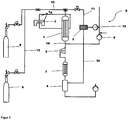
- a particularly preferred system includes 0 according to FIG. 1 downstream of the device 1 with at least two reactors 1a a compressor 2, which is associated with a condenser 3 and the condenser 3 downstream of a Roh etcablass 4 or crude product container 4 is assigned. Further, downstream of the condenser 3, in particular on or behind the product container 4, the membrane 5 is provided for adjusting the hydrogen partial pressure of the resulting phase. The resulting phase is brought into contact with the membrane 5 and then obtained a stream of educts, which is transferred by means of a conduit 11, which is associated upstream of the device 1, into the device.
- monosilane from the monosilane source 9 can be metered into this stream of starting materials in order either to adjust the content of monosilane in% by volume or to regulate the pressure of the stream of educts.
- a vacuum pump 6 associated with the reactor can be used to start the process and regulate the pressure during the ongoing reaction.
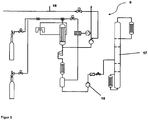
- a device 17 for separating the polysilanes preferably a column 17 or a multi-column system 17, is attached to the crude product container or the crude product outlet, particularly preferably a rectification column for the fractional distillation of the crude product mixture.
- a multi-column system is preferably used. If appropriate, the column or the multi-column system may be preceded by a product feed pump.
- High-boiling tetrasilane, pentasilane and / or hexasilane, and ultrahigh molecular weight polysilanes such as heptasilane, ocatsilane as high boilers, can preferably be obtained as low boilers at the top of the column.
- a multi-column system known to those skilled in the art can be used.
- a particularly preferred installation 0 has an arrangement of the abovementioned installation parts, in order to enable a cyclic process of the aforementioned method to be carried out.
- the apparatus 1, comprising at least two reactors 1a, downstream of a compressor 2 is assigned, as in FIG. 1 shown.
- the device is preferably arranged vertically above the condenser.
- the compressor 2 is associated with a condenser 3 and downstream of the condenser 3, the plant has the hydrogen-permeable membrane 5, wherein the one side of the membrane 5 and the reactor 1, a line 12 is assigned, further downstream of the condenser 3 is a product outlet 4 or Product container 4 provided; and on another side of the membrane 5 discharged hydrogen is discharged through a further line 15, which may be associated with an Intergastechnisch for hydrogen separation.
- Monosilane was continuously evaporated from a compressed gas cylinder 9 by means of a pressure control via the Eduktzu Adjust 12 in the vertical device 1 with series-connected ozonizers 1a and passed over the gas discharge paths with dielectric of the ozonizers.
- the non-thermal plasmas in the ozonizers were at minus 10 ° C and at 60 mbar abs. operated.
- the stream of starting materials consisted of 10% by volume of monosilane and 90% by volume of hydrogen.
- the formation of silyl radicals and higher radicals took place, which reacted to form polysilanes and together with not converted educts formed the resulting phase.
- the liquid under the process conditions polysilanes ran down from.
- polysilanes were enriched as a mixture with increased levels of tetrasilane and pentasilane, which were pumped from the product pump 16 to the distillation column 17 to be fractionally distilled there.
- FIG. 1 shows a schematic representation of a system 0 for performing a cycle.
- FIG. 2 shows a schematic representation of a system 0 with device 17 for the separation of polysilanes, here a distillation column 17th
Landscapes
- Chemical & Material Sciences (AREA)
- Organic Chemistry (AREA)
- Inorganic Chemistry (AREA)
- Chemical Kinetics & Catalysis (AREA)
- Health & Medical Sciences (AREA)
- General Health & Medical Sciences (AREA)
- Toxicology (AREA)
- Silicon Compounds (AREA)
- Organic Low-Molecular-Weight Compounds And Preparation Thereof (AREA)
- Physics & Mathematics (AREA)
- Engineering & Computer Science (AREA)
- Plasma & Fusion (AREA)
Description
- Die Erfindung betrifft ein Verfahren zur Herstellung von Polysilanen durch Umsetzung von Monosilan in Gegenwart von Wasserstoff in einem Plasma sowie eine Anlage zur Durchführung dieses Verfahrens.
- In der Mikroelektronik wird Disilan zur Abscheidung von Silizium-Schichten eingesetzt, das allerhöchsten Reinheitsanforderungen genügen muss. Bislang sind jedoch nur Verfahren bekannt, bei denen Katalysatoren zum Einsatz kommen. So offenbart die
JP 02-184513 - Die
WO 2008/098640 A2 offenbart ein Verfahren zur Herstellung von Hexachlordisilan, das in einem zweiten Verfahrensschritt katalytisch zu Disilan hydriert werden kann. Dieses zweistufige Verfahren ist nicht für die kostengünstige Herstellung von hochreinem Disilan geeignet. - Aus der
DE 36 39 202 ist ein weiteres Verfahren zur Herstellung von Disilan mit dem Nachteil einer Bildung von signifikanten Mengen an elementarem Silizium während der Herstellung von Disilan bekannt. Der Reaktor kann in diesem Verfahren nur diskontinuierlich betrieben werden und muss nach sehr kurzen Produktionszeiten aufwendig gereinigt werden. Ein weiterer Nachteil besteht in den hohen Ausbeuteverlusten, die einerseits durch die Siliziumabscheidung und anderseits durch Verluste an Disilan oder Trisilan aufgrund von Strippeffekten bei der Abtrennung von Wasserstoff aus den Reaktionsprodukten entstehen. Diese Ausbeuteverluste können zwar bei einer Synthese über Hexachlordisilan vermieden werden, jedoch kommt es durch die katalytische Hydrierung wiederum zu einer Kontamination des Disilans und Trisilans. - Die Patentanmeldung
EP 0268756 A2 offenbart ein Verfahren zur Herstellung von Disilan aus Monosilan, bei dem ein Gemisch aus Monosilan und Wasserstoff einer Plasmaentladung ausgesetzt wird. - In
FR 2743554 A1 -
US 4604274 B beschreibt eine Konversionsmethode von Silanen zu Disilan durch Bestrahlung der Silane mit infrarotem Laserlicht. - Disilane werden auch gewonnen, indem gasförmiges Monosilan durch einen Reaktionsraum geleitet wird, in dem eine Plasmaentladung stattfindet. Dies ist in der Patentschrift
US 5505913 B offenbart. - Aufgabe der vorliegenden Erfindung war die Bereitstellung eines Verfahrens und einer Anlage, die die genannten Nachteile des Standes der Technik vermeidet und vorzugsweise eine kontinuierliche Herstellung von Polysilanen erlaubt. Ferner sollten die Polysilane bereits als Gemisch in hoher- bis höchster Reinheit isoliert werden können. Vorzugsweise sollten eine Auftrennung der Polysilane nur noch mit dem Zweck einer Erhöhung des Gehaltes der reinen Polysilane und nicht primär einer Aufreinigung dienen. Zudem bestand die Aufgabe, ein besonders wirtschaftliches Verfahren im technischen Maßstab bereitzustellen.
- Gelöst werden die Aufgaben durch das erfindungsgemäße Verfahren sowie durch die erfindungsgemäße Anlage gemäß den Merkmalen der Patentansprüche 1 und 14.
- Überraschend wurde festgestellt, dass zur selektiven Herstellung von Polysilanen Gasphasenbehandlungen eines Strom von Eduktens umfassend Monosilan mit definiertem Monosilanpartialdruck im Gasgemisch in Gegenwart von Wasserstoff in nicht-thermischen Plasmen bei Temperaturen unter 40 °C und vorzugsweise vermindertem Druck genutzt werden können.
- Gegenstand der Erfindung ist somit ein Verfahren zur Herstellung von Polysilanen mit mindestens zwei über eine kovalente Einfachbindung aneinander gebundenen Siliziumatomen (Si-Si), insbesondere Gemischen an linearen, verzweigten und/oder cyclischen Polysilanen ausgewählt aus Disilan, Trisilan, Tetrasilan, Pentasilan, Hexasilan, Heptasilan, Octasilan, Nonasilan, Decasilan, Undecasilan, Dodecasilan und/oder deren Strukturisomeren, bevorzugt von Polysilanen der nachfolgenden allgemeinen Formeln II, III, IV und/oder V, indem
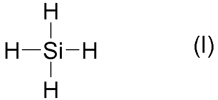
- i) ein Strom von Edukten umfassend Monosilan der allgemeinen Formel I und Wasserstoff,

- ii) mindestens einer Gasentladung, vorzugsweise zwei bis zehn nicht-thermischen Plasmen, ausgesetzt wird, bevorzugt bei einem Druck zwischen 0,05 mbarabs. bis 15000 mbarabs., besonders bevorzugt bei vermindertem Druck, und
- iii) in der resultierenden Phase ein definiertes Verhältnis des Wasserstoffpartialdrucks zum Partialdruck der unter den gewählten Bedingungen gasförmigen Silane eingestellt wird, und in der resultierenden Phase das definierte Verhältnis des Wasserstoffpartialdrucks zum Partialdruck der unter den gewählten Bedingungen gasförmigen Silane mittels einer Wasserstoff durchlässigen Membran eingestellt wird,
- Die Einstellung der Partialdrücke geschieht erfindungsgemäß mittels einer Wasserstoff durchlässigen Membran, die vorzugsweise nur für Wasserstoff und im Wesentlichen nicht für Silane permeabel ist. Im Schritt iii) wird ein Polysilangemisch aus der resultierenden Phase gewonnen, und in der resultierenden Phase das definierte Verhältnis des Wasserstoffpartialdrucks zum Partialdruck der unter den gewählten Bedingungen gasförmigen Silane mittels einer Wasserstoff durchlässigen Membran eingestellt.
- Der Begriff Polysilan umfasst die homologe Reihe der rein Wasserstoff substituierten Silane gemäß IUPAC-Nomenklatur, die als erfindungsgemäße Polysilane mindestens zwei miteinander kovalent verknüpfte Si-Atome (Si-Si) aufweisen. Die Polysilane weisen ein ausschließlich mit Wasserstoffatomen substituiertes Silizium-Grundgerüst auf und umfassen lineare, verzweigte und/oder cyclische Polysilane, wie n-Polysilane, iso-Polysilane, neo-Polysilane und/oder cyclo-Polysilane. Die linearen und verzweigten Polysilane können anhand der allgemeinen Formel II SinCl2n+2 mit n grösser gleich 2 sowie die cyclischen Polysilane anhand der allgemeinen Formel III SinCl2n mit n grösser gleich 3 beschrieben werden. Idealisiert lassen sich hochmolekulare Polysilane über die Formel IV SinCl2n mit n grösser gleich 3 als auch anhand der Formel V mit weiter reduziertem Wasserstoffanteil beschreiben ((SiH<2)n). Unter Polysilanen gemäß der Erfindung werden sowohl einzelne Polysilane als auch Gemische von Polysilanen der allgemeinen Formeln II, III, IV und/oder V mit n größer gleich 2 bis 100 erfasst, insbesondere mit n größer gleich 2 bis 25, bevorzugt mit 4 bis 25, besonders beovrzugt mit n gleich 4 bis 15, wobei die Polysilane bevorzugt unter den Verfahrensbedingungen flüssig bis hochviskos sind. Daher umfassen die Polysilane entsprechend der Erfindung vorzugsweise Gemische hoch- bis höchstreine Silane ausgewählt aus Disilan, Trisilan, Tetrasilan, Pentasilan, Hexasilan, Heptasilan, Octasilan, Nonasilan, Decasilan, Undecasilan, Dodecasilan, Tridecasilan, Tetradecasilan, Pentadecasilan, Cyclopentasilan, Cyclohexasilan, sowie jeweils deren Strukturisomere als auch hochmolekulare Polysilane bis vorzugsweise n kleiner gleich 25, wobei das Polysilan mindestens Tetrasilan und/oder Pentasilan umfasst.
- Ein besonderer Vorteil des erfindungsgemässen Verfahrens ist die Möglichkeit der direkten Weiterverarbeitung der Polysilane zur Abscheidung von hochreinen Siliziumschichten mit Solarsiliziumqualität als auch Halbleiterqualität ohne zusätzliche Reinigungsschritte. Es erfolgt lediglich eine Trennung des Polysilangemisches in die einzelnen Polysilane mittels destillativer Aufarbeitung, um definierte Produkteigenschaften der Polysilane bei der Weiterverarbeitung sicherzustellen. Erfindungsgemäß sind diese Polsilane im Wesentlichen frei von Halogenen, insbesondere sind sie im Wesentlichen chlorfrei, bevorzugt ist ihr Gehalt an Chlor unter 1x10⁵ Gew.-%, besonders bevorzugt unter 1x10⁻⁶ Gew.-% bis hin zur Nachweisgrenze von 1x10⁻¹⁰ Gew.-%. Die erfindungsgemäß erhältlichen Polysilane sind somit frei von Halogen, wie Chlor.
- Gegenstand der Erfindung ist somit ein Verfahren zur Herstellung von Polysilanen und Polysilangemischen i) wobei ein Strom von Edukten umfassend Monosilan der allgemeinen Formel I und Wasserstoff im Gasgemisch, ii) nicht-thermischen Plasmen bei einem Druck zwischen 0,1 mbarabs. bis 1000 mbarabs. ausgesetzt wird, bevorzugt bei einem Druck zwischen 1 mbarabs. bis 950 mbarabs., und iii) in der resultierenden Phase ein Verhältnis des Wasserstoffpartialdrucks zum Partialdruck der unter den gewählten Bedingungen gasförmigen Silane, insbesondere zum Partialdruck des Monosilans, eingestellt wird, und Polysilangemische gewonnen werden, wobei der Druck im Verfahrensschritt iii) gegenüber dem Druck in der Verfahrensstufe ii) erhöht ist und iv) das Polysilangemisch destilliert wird.
- Als Edukte werden hoch- bis höchstreines Monosilan und Wasserstoff eingesetzt, die vorzugsweise jeweils dem folgenden Verunreinigungsprofil entsprechen. Als Gesamtverunreinigung weist das Monosilan oder der Wasserstoff kleiner gleich 100 Gew.-ppm bis 1 Gew.-ppt auf, insbesondere bis zur Nachweisgrenze, bevorzugt kleiner gleich 50 Gew.-ppm, weiter bevorzugt kleiner gleich 25 Gew.-ppm. Die Gesamtverunreinigung umfasst dabei eine Verunreinigung mit Bor, Phosphor und metallischen Elementen, die nicht Silizium entsprechen. Besonders bevorzugt ist die Gesamtverunreinigung jeweils unabhängig für das Monosilan und den Wasserstoff für die nachfolgend genannten Elemente kleiner gleich: Aluminium von 15 Gew.-ppm bis 0,0001 Gew.-ppt, und/oder
- a. Bor von 5 bis 0,0001 Gew.-ppt,
bevorzugt im Bereich von 3 Gew.-ppm bis 0,0001 Gew.-ppt, und/oder - b. Calcium von 2 Gew.-ppm bis 0,0001 Gew.-ppt, und/oder
- c. Eisen von 5 Gew.-ppm bis 0,0001 Gew.-ppt,
bevorzugt von 0,6 Gew.-ppm bis 0,0001 Gew.-ppt, und/oder - d. Nickel von 5 Gew.-ppm bis 0,0001 Gew.-ppt,
bevorzugt von 0,5 Gew.-ppm bis 0,0001 Gew.-ppt, und/oder - e. Phosphor von 5 Gew.-ppm bis 0,0001 Gew.-ppt,
vorzugsweise von 3 Gew.-ppm bis 0,0001 Gew.-ppt, und/oder - f. Titan kleiner gleich 10 Gew.-ppm,
vorzugsweise kleiner gleich 2 Gew.-ppm, weiterhin bevorzugt
von 1 Gew.-ppm bis 0,0001 Gew.-ppt,
besonders bevorzugt von 0,6 Gew.-ppm bis 0,0001 Gew.-ppt,
ganz besonders bevorzugt von 0,1 Gew.-ppm bis 0,0001 Gew.-ppt, und/oder - g. Zink kleiner gleich 3 Gew.-ppm,
bevorzugt von 1 Gew.-ppm bis 0,0001 Gew.-ppt,
besonders bevorzugt von 0,3 Gew.-ppm bis 0,0001 Gew.-ppt, - h. Kohlenstoff und/oder
- i Halogene,
- Es wurde gefunden, dass bei einem gegebenen Strom von Edukten mit einem Verhältnis an Wasserstoff und Silan jeweils in Volumenprozent (Vol.-%) von 15 : 1 bis 1 : 5, bevorzugt zwischen 10 : 1 bis 5 : 1, besonders bevorzugt zwischen 10 : 1 bis 8 : 1, weiter bevorzugt bei etwa 90 Vol.-% Wasserstoff und 10 Vol.-% Monosilan, d.h. bei einem Verhältnis von etwa 9:1, die besten Ausbeuten an Polysilanen erhalten werden, wenn der Druck im Gasentladungsreaktor zwischen 10 bis 60 mbarabs. beträgt.
- So konnte für einen Strom von Edukten von 90 Vol.-% Wasserstoff und 10 Vol.-% Monosilan nach Durchströmen zweier Gasentladungsanordnungen nicht-thermischer Plasmen bei einem Druck von 10 mbarabs. Polysilan bei kontinuierlicher Betriebsweise erhalten werden. Wird der Druck leicht weiter erhöht, kann die Ausbeute weiter gesteigert werden.
- Gemäß einer besonders bevorzugten Verfahrensführung wird der Strom von Edukten im Verfahrensschritt ii) zwei bis zehn Gasentladungen ausgesetzt. Generell kann es bevorzugt sein, wenn der Strom von Edukten mehrere Gasentladungsanordnungen nicht-thermischer Plasmen durchströmt, insbesondere 2, 3, 4, 5, 6, 7, 8, 9 oder 10 nicht-thermische Plasmen, bevorzugt sind 2 bis 4 Plasmen. Je nach angestrebter Molekulargewichtsverteilung der Polysilane wird der Strom von Edukten mit einer größeren Anzahl oder geringeren Anzahl nicht-thermischer Plasmen in Kontakt gebracht. Zur Herstellung von Polysilanen mit hohem Molekulargewicht wird der Strom von Edukten mit mehreren in Reihe geschalteten nicht-thermischen Plasmen in Kontakt gebracht.
- Zur optimalen Durchführung des Verfahrens wird der Strom von Edukten bevorzugt in Schritt ii) bei einem Druck von 5 mbarabs. bis 100 barabs., besonders bevorzugt von 7,5 mbarabs. bis 100 mbarabs., weiter bevorzugt von 10 mbarabs. bis 80 mbarabs. nicht-thermischen Plasmen in einem Temperaturbereich von - 60 °C bis 10 °C ausgesetzt, vorzugsweise von -40 bis 0 °C, weiter bevorzugt um -10 °C plus/minus 5 °C.
- Ebenso ist es bevorzugt, wenn im Verfahrensschritt ii) die Gasentladung bei
- einem Druck zwischen 0,1 mbarabs. bis 1000 mbarabs.. erfolgt,
- bevorzugt von 0,1 bis 800 mbarabs.,
- besonders bevorzugt von 1 mbarabs. bis 100 mbarabs.
- Druckbereich von 10 bis 100 mbarabs.,
- vorzugsweise von 10 bis 80 mbarabs.
- Zur Herstellung der Polysilane werden die Reaktionsbedingungen der nicht-thermischen Plasmen selektiv auf die Anregung und Spaltung der Si-H-Bindung oder von Si-Si-Bindungen eingestellt. Innerhalb der bevorzugten Druck- und Temperaturbereiche kann das nichtthermische Plasma selektiv die Si-H-Bindung und/oder die Si-Si-Bindungen so weit anregen, dass es selektiv zur Radikalbildung und anschließend zur Rekombination mit anderen Radikalen kommt. Unter den gewählten Verfahrensbedingungen werden bevorzugt Silylradikale (SiH3-Radikale), SiH2-Radikale und entsprechende Radikale der gebildeten Polysilane gebildet. Durch Rekombination und Kettenwachstum der vorgenannten Radikale können verzweigte Polysilane erhalten werden.
- Es wird vermutet, dass es bei einer mittleren Elektronenenergie von 5 eV im schwach ionisierenden nicht-thermischen Plasma zur selektiven Bildung von Silylradikalen durch Anregung und Spaltung der Si-H-Bindung kommt. Für einen weiteren Kettenaufbau findet vermutlich eine Insertion von SiH2-Radialen in Si-H oder Si-Si-Bindungen von Disilanen, Trisilan, Tetrasilan, und höheren Silanen statt. Ist der Energieeintrag zu hoch, beispielsweise im Bereich von 12,3 eV, dann würden statt einer selektiven Radikalbildung unerwünschte SiH3 +-Ionen gebildet werden. Diese würden zerfallen und zur Abscheidung von Silizium führen. Für eine hohe Polysilanausbeute ist es daher entscheidend, die Prozessbedingungen der nicht-thermischen Plasmen optimal auf die selektive Radikalbildung und die Möglichkeiten zur Rekombination zu Polysilanen einzustellen und zugleich die Bildung weiterer Zerfallsprodukte zu unterbinden. Dies gelingt bei optimal aufeinander abgestimmtem Druck und Energieeintrag.
- Das dabei gebildete Polysilangemisch kann anschließend über eine geeignete Temperatur- und Druckeinstellung, insbesondere nach Schritt III) auskondensiert werden, indem der Druck mittels eines Verdichters auf einen Druck von 0,1 barabs. bis 100 barabs., insbesondere von 1 barabs. bis 100 barabs., vorzugsweise von 1 bis 10 barabs., und in einem Temperaturbereich von - 60 °C bis 20 °C eingestellt wird. Zur vollständigen Abtrennung wird bevorzugt eine zweistufige Verfahrensweise angewendet, in der in einem ersten Teilschritt am Kondensator eine Temperatur im Bereich von -20 bis 300 °C bei einem Druck zwischen 0,1 bis 10 barabs. eingestellt wird und nachfolgend im Rohproduktbehälter oder Rohproduktablass bei vorzugsweise gleichem Druck von - 20 bis 40 °C die vollständige Abtrennung durch Kondensation der Polysilane aus der resultierenden Phase erfolgt.
- Diese resultierende Phase wird vorzugsweise mit einer für Wasserstoff permeablen Membran in Kontakt gebracht, wobei sich ein definiertes Verhältnis des Wasserstoffpartialdrucks zum Partialdruck der unter den gewählten Bedingungen gasförmigen Silane, insbesondere des nicht umgesetzten Monosilans, einstellen kann. Die auf diese Weise behandelte resultierende Phase wird nach der teilweisen Abtrennung von Wasserstoff erneut dem Strom von Edukten, welchem weiteres Monosilan zudosiert werden kann, zum nichtthermischen Plasma geführt.
- Nach dem erfindungsgemässen Verfahren werden lineare, verzweigte und/oder cyclische Polysilane umfassend Tetrasilan, Pentasilan und/oder Hexasilan erhalten, die vorzugsweise bereits hoch- oder höchstrein entsprechend nachstehender Definition als Polysilangemisch erhalten werden können. Mittels Destillation können die Polysilane auf einfache Weise in die einzelnen Polysilane getrennt werden.
- Die vorstehend genannte Verfahrensweise erlaubt die einfache Rückführung von nicht umgesetztem Edukt der allgemeinen Formel I, das nach Bedarf erneut dem nicht-thermischen Plasma zugeführt werden kann. Zur vollständigen Umsetzung des eingesetzten Monosilans zu Polysilanen werden vorzugsweise zwei bis fünf nicht-thermische Plasmen im Schritt ii) durchlaufen, wobei das Verfahren zusätzlich als Kreisprozess betrieben werden kann, indem die Verfahrensschritte i), ii) und iii) durchlaufen werden. Das mittels der Umsetzung im nicht-thermischen Plasma erhaltene Polysilan kann bereits über die Verfahrensschritte i, ii) und iii) rein erhalten werden. Eine Auftrennung und ggf. zusätzliche weitere Aufreinigung der Silane kann anschließend kontinuierlich oder diskontinuierlich destillativ erfolgen. Die destillative Aufarbeitung kann je nach erhaltenem Produktgemisch mit einer Kolonne oder bevorzugt in einem Mehrkolonnensystem erfolgen, wenn verschiedene Polysilane aufgetrennt werden sollen.
- Das erfindungsgemäße Verfahren liefert Pentasilan, das in höchster Reinheit von den übrigen Polysilanen isoliert werden kann. In einem 29Si-NMR-Spektrum sind neben dem Signal des Pentasilans keine weiteren Produkte nachweisbar. Die Verunreinigung des Polysilans, insbesondere des Pentasilans, mit anderen Metallverbindungen liegt im Bereich von 1000 Gew.-ppb bis 100 Gew.-ppt, bevorzugt weniger. Ein besonderer Vorteil der nach dem erfindungsgemäßen Verfahren hergestellten Polysilane ist, dass sie frei von Chloriden und/oder sonst üblicherweise verwendeten Katalysatorrückständen sind.
- Besonders bevorzugt ist das erhaltene Polysilan sowie die jeweils isolierten einzelnen Polysilane höchstrein und weist in Summe jeweils eine Gesamtverunreinigung von kleiner gleich 100 Gew.-ppm bis zur Nachweisgrenze, insbesondere bis 1 Gew.-ppt auf, bevorzugt ist die Gesamtverunreinigung kleiner gleich 50 Gew.-ppm. Als Gesamtverunreinigung gilt eine Verunreinigung mit Bor, Phosphor und metallischen Elementen, die nicht Silizium entsprechen. Besonders bevorzugt ist die Gesamtverunreinigung des Polysilans für die nachfolgend genannten Elemente kleiner gleich:
- aa.Aluminium von 15 Gew.-ppm bis 0,0001 Gew.-ppt, und/oder
- bb. Bor von 5 bis 0,0001 Gew.-ppt,
bevorzugt im Bereich von 3 Gew.-ppm bis 0,0001 Gew.-ppt, und/oder - cc. Calcium kleiner 2 Gew.-ppm,
bevorzugt von 2 Gew.-ppm bis 0,0001 Gew.-ppt, und/oder - dd. Eisen von 5 Gew.-ppm bis 0,0001 Gew.-ppt,
vorzugsweise von 0,6 Gew.-ppm bis 0,0001 Gew.-ppt, und/oder - ee. Nickel von 5 Gew.-ppm bis 0,0001 Gew.-ppt,
vorzugsweise von 0,5 Gew.-ppm bis 0,0001 Gew.-ppt, und/oder - ff. Phosphor von 5 Gew.-ppm bis 0,0001 Gew.-ppt,
bevorzugt von 3 Gew.-ppm bis 0,0001 Gew.-ppt, und/oder - gg. Titan kleiner gleich 10 Gew.-ppm,
kleiner gleich 2 Gew.-ppm,
bevorzugt von 1 Gew.-ppm bis 0,0001 Gew.-ppt,
weiter bevorzugt von 0,6 Gew.-ppm bis 0,0001 Gew.-ppt,
besonders bevorzugt von 0,1 Gew.-ppm bis 0,0001 Gew.-ppt, und/oder - hh. Zink kleiner gleich 3 Gew.-ppm,
bevorzugt von 1 Gew.-ppm bis 0,0001 Gew.-ppt,
weiter bevorzugt von 0,3 Gew.-ppm bis 0,0001 Gew.-ppt, - ii. Kohlenstoff, und/oder
- jj. Halogene,
- Zusätzlich oder alternativ zu einem der vorgenannten Merkmale ist es bevorzugt, im Verfahrensschritt iii) die resultierende Phase auf einen Druck von 0,05 barabs. bis 100 barabs. einzustellen, beispielsweise auf 0,1 bis 100 barabs., vorzugsweise auf einen Druck von 1 barabs. bis 100 barabs., weiter bevorzugt auf einen Druck von 0,5 barabs., besonders bevorzugt auf 1 barabs. bis 60 barabs.. Besonders bevorzugt ist ein Druck von 1 bis 10 barabs..
- Als Wasserstoff permeable Membran kann vorzugsweise eine Membran im Verfahren und/oder in der Anlage eingesetzt werden, die die folgenden Materialien umfasst: Quarz, geeignetes Metall, geeignete metallische Legierung, Keramik, Zeolith, organisches Polymer und/oder eine Kompositmembran umfassend einen mindestens zweischichtigen Aufbau mit einem oder mehreren der vorgennannten Materialien. Um als Material für die Wasserstoff permeable Membran geeignet zu sein, ist es notwendig, dass das Material, z. B. Quarz oder Palladium, mit oder ohne Silber, Poren einer definierten Größe aufweist, durch die Wasserstoff diffundieren kann, und die im Wesentlichen undurchlässig für Monosilan sind. Eine bevorzugt einsetzbare Membran kann beispielsweise eine Keramikmembran mit einem Schichtaufbau umfassen, die eine erste mikroporöse Schicht mit Poren kleiner 2 nm aufweist, an die sich eine mesoporöse Schicht mit Poren von 3 bis 10 nm anschließt. Vorzugsweise kann eine makroporöse Schicht mit großen Poren bis 100 nm vorgesehen sein. Dabei ist es bevorzugt, dass die makroporöse Schicht ein poröses keramisches Material oder ein gesintertes Metall ist.
- Geeignete Membranen können bevorzugt die folgenden Materialien umfassen: Palladium, eine Palladiumlegierung, wie PdAI, PdCu, Quarz und/oder ein organisches synthetisches Polymer, wie vorzugsweise Hohlfasermembranen, wobei die Membranen bevorzugt für Wasserstoff permeabel sind. Bevorzugte Hohlfasermembranen können aus Polyamiden, Polyimiden, Polyamid-imiden oder auch aus Mischungen dieser hergestellt sein. Sofern eine Palladiummembran gewählt wird, kann sie beispielsweise durch chemische Gasphasenabscheidung, elektrochemischer Abscheidung, Hochgeschwindigkeitsflammspritzen oder physikalischer Gasphasenabscheidung, dem sogenannten Elektronenstrahlverdampfen oder dem sogenannten Sputtern hergestellt werden.
- Aufgrund der hohen Reinheitsanforderungen in Bezug auf eine Verunreinigung mit metallischen Elementen wird eine höchstreine Quarzmenbram im Verfahren und/oder in der Anlage bevorzugt genutzt. Diese Membran sollte eine Druckstabilität größer 1 barabs., vorzugsweise größer 2 barabs., besonders bevorzugt größer 3 barabs. aufweisen und kann vorzugsweise auf einem porösen Si-Träger oder Aluminiumoxid-Träger aufgebracht sein. Entsprechendes gilt für Palladium basierte Membranen, die aus einer Palladium-Aluminium-, Palladium-Silber-, oder Palladium-Kupfer-Legierung hergestellt sein können, und vorzugsweise eine Druckstabilität größer 3 barabs. auf einem porösem Si-Träger, einem sogenanten Lochmaskenträger oder Aluminiumoxid-Träger aufweisen.
- Jedes nichtthermische Plasma basiert auf anisothermem Plasma. Es wird in einem PlasmaReaktor erzeugt, in dem eine plasmaelektrische Stoffumwandlung induziert wird. Für diese Plasmen ist eine hohe Elektronentemperatur Te > 104 K und relativ niedrige Gastemperatur TG ≈ 103 K charakteristisch. Die für die chemischen Prozesse notwendige Aktivierungsenergie erfolgt überwiegend über Elektronenstöße. Typische nichtthermische Plasmen können beispielsweise durch Glimmentladung, HF-Entladung, Hohlkathodenentladung oder Koronarentladung erzeugt werden. Der Arbeitsdruck, bei dem die erfindungsgemässe Plasmabehandlung durchgeführt wird, liegt vorzugsweise im Bereich von 1 bis 1000 mbarabs., wobei die zu behandelnde Phase vorzugsweise auf eine Temperatur von -40 °C bis 10 °C, eingestellt ist. Für die Definition des nichtthermischen Plasmas und der homogenen Plasmakatalyse wird auf die einschlägige Fachliteratur verwiesen, wie beispielsweise auf "Plasmatechnik: Grundlagen und Anwendungen - Eine Einführung"; Autorenkollektiv, Carl Hanser Verlag, München/Wien; 1984, ISBN 3-446-13627-4.
- Gleichfalls Gegenstand der Erfindung ist eine Anlage, insbesondere zur Durchführung des vorgenannten Verfahrens, die eine Vorrichtung umfassend mindestens zwei Reaktoren, insbesondere zwei in Reihe geschaltete Reaktoren, zur Erzeugung von Gasentladungen aufweist, der stromaufwärts eine Eduktzuführung und stromabwärts eine Wassersstoff durchlässige Membran zugeordnet ist, um ein definiertes Verhältnis des Wasserstoffpartialdrucks zum Partialdruck der gasförmigen Silane in der resultierenden Phase einzustellen, ferner weist die Anlage mindestens eine weitere Vorrichtung zur Auftrennnung der Polysilane auf, wobei die weitere Vorrichtung bevorzugt eine Kolonne zur destillativen Aufarbeitung der Polysilane ist. Vorzugsweise weist die Anlage ein Mehrkolonnensystem mit mindestens 2 Kolonnen, bevorzugt mit 2 bis 5 Kolonnen auf.
- Zusätzlich zu den zwei Reaktoren kann die Anlage auch einen oder mehrere weitere Reaktoren aufweisen, die in Reihe und/oder parallel geschaltet werden. Bevorzugt können 2, 3, 4, 5, 6, 7, 8, 9 oder 10 Reaktoren in Reihe geschaltet werden. Erfindungsgemäss sind die Reaktoren vorzugsweise Ozonisatoren. Ein grosser Vorteil besteht in der alternativ möglichen Verwendung von handelsüblichen Ozonisatoren, so dass die Investitionskosten wesentlich gesenkt werden. Die Reaktoren der Erfindung sind zweckmässig mit Glasrohren, insbesondere mit Quarzglasrohren ausgestattet, wobei die Rohre bevorzugt parallel bzw. koaxial angeordnet und mittels Spacern aus inertem Material beabstandet sind. Als inertes Material eignet sich insbesondere Teflon, Glas sowie generell Low-K-Materialien, die eine geringe Dielektrizitätskonstante aufweisen. Als Materialien mit einer geringen Dielektrizitätskonstante gelten jene, deren Dielektrizitätskonstanten kleiner gleich 9 sind. Alternativ können die Reaktoren statt mit Glasrohen auch mit röhrenförmigen, dielektrischen Komponenten ausgestattet sein. Es ist bekannt, dass die eingekoppelte Elektronenenergie für die Plasmaentladung "E" abhängig vom Produkt aus Druck "p" und Elektrodenabstand "d" (p·d) ist. Für das erfindungsgemässe Verfahren liegt das Produkt aus Elektrodenabstand und Druck in der Regel im Bereich von 0,001 bis 300 mm·bar, vorzugsweise von 0,05 bis 100 mm·bar, besonders bevorzugt von 0,08 bis 0,3 mm·bar, insbesondere bei 0,1 bis 0,2 mm·bar. Die Entladung kann mittels verschiedenartiger Wechselspannungen oder gepulster Spannungen von 1 bis 106 V angeregt werden. Dabei kann der Kurvenverlauf der Spannung u. a. rechteckig, trapezförmig, gepulst oder stückweise aus einzelnen zeitlichen Verläufen zusammengesetzt sein. Besonders geeignet sind pulsförmige Anregungsspannungen, sie ermöglichen eine gleichzeitige Ausbildung der Entladung im gesamten Entladungsraum des Reaktors. Die Impulsdauer beim Pulsbetrieb richtet sich nach der Zusammensetzung, der Verweildauer und dem Druck des Strom von Edukten. Sie liegt bevorzugt zwischen 10 ns und 1 ms. Bevorzugte Spannungsamplituden liegen bei 10 Vp bis 100 kVp, bevorzugt 100 Vp bis 10 Vp, insbesondere bei 50 bis 5 Vp, in einem Mikrosystem. Die Frequenz der Wechselspannung kann zwischen 10 MHz und 10 ns-lmpulsen (Tastverhältnis 10 : 1) bis zu niedrigen Frequenzen im Bereich von 10 bis 0,01 Hz eingestellt werden. Beispielsweise kann am Reaktor eine Wechselspannung mit einer Frequenz von 1,9 kHz und einer Amplitude von 35 kV "Peak to Peak" angelegt werden. Der Leistungseintrag beträgt ungefähr 40 W.
- Ebenfalls Gegenstand der Erfindung ist eine bevorzugte Anlage 0, wie in
Figur 1 dargestellt, der stromabwärts der Vorrichtung 1 mit mindestens zwei Reaktoren 1a ein Verdichter 2 zur Erhöhung des Drucks der resultierenden Phase zugeordnet ist, insbesondere ist der Verdichter 2 zwischen der Vorrichtung 1 und der Membran 5 vorgesehen. Der Verdichter erhöht den Druck der resultierenden Phase nach Austritt aus dem Reaktor, beispielsweise von etwa 60 mbarabs. auf 2,5 barabs.. Die verdichtete resultierende Phase wird anschließend über einen stromabwärts angeordneten Kondensator 3 geleitet, um das gebildete Polysilan zu kondensieren, während nicht umgesetztes Monosilan und ggf. Disilan oder weitere unter den Bedingungen gasförmige Silane und Wasserstoff in der Gasphase verbleiben. - Somit umfasst eine besonders bevorzugte Anlage 0 gemäß
Figur 1 stromabwärts der Vorrichtung 1 mit mindestens zwei Reaktoren 1a einen Verdichter 2, dem ein Kondensator 3 zugeordnet ist und dem Kondensator 3 ist stromabwärts ein Rohproduktablass 4 oder Rohproduktbehälter 4 zugeordnet. Weiter ist stromabwärts des Kondensators 3, insbesondere an oder hinter dem Produktbehälter 4 die Membran 5 zur Einstellung des Wasserstoffpartialdrucks der resultierenden Phase vorgesehen. Die resultierende Phase wird mit der Membran 5 in Kontakt gebracht und anschließend ein Strom von Edukten erhalten, der mittels einer Leitung 11, die stromaufwärts der Vorrichtung 1 zugeordnet ist, in die Vorrichtung überführt. Diesem Strom von Edukten kann weiteres Monosilan aus der Monosilanquelle 9 zudosiert werden, um entweder den Gehalt an Monosilan in Vol.-% einzustellen oder auch den Druck des Strom von Eduktens zu regulieren. Eine Vakuumpumpe 6, die dem Reaktor zugeordnet ist, kann zum Anfahren des Verfahrens und zur Regulierung des Druckes während der laufenden Umsetzung genutzt werden. - In einer bevorzugten Ausführungsform, die in
Figur 2 dargestellt ist, schliesst sich an den Rohproduktbehälter bzw. den Rohproduktablass eine Vorrichtung 17 zur Auftrennung der Polysilane, vorzugsweise eine Kolonne 17 oder ein Mehrkolonnensytem 17 an, besonders bevorzugt eine Rektifikationskolonne, zur fraktionierten Destillation des Rohproduktgemisches. Zur vollständigen Auftrennung der Poylsilane wird vorzugsweise ein Mehrkolonnensystem genutzt. Sofern sinnvoll, kann der Kolonne oder dem Mehrkolonnensystem eine Produktförderpumpe vorgeschaltet sein. Am Kolonnenkopf können als Leichtsieder vorzugsweise höchstreines Tetrasilan, Pentasilan und/oder Hexasilan und am Sumpf höchstreine höhermolekulare Polysilane, wie Heptasilan, Ocatsilan als Schwersieder erhalten werden. Zur weiteren Auftrennung der Silane kann ein dem Fachmann geläufiges Mehrkolonnensystem eingesetzt werden. - Eine besonders bevorzugte Anlage 0 weist eine Anordnung der vorgenannten Anlagenteile auf, um die Durchführung eines Kreisprozesses des vorstehend genannten Verfahrens zu ermöglichen. In dieser Anlage 0 ist der Vorrichtung 1, umfassend mindestens zwei Reaktoren 1a, stromabwärts ein Verdichter 2 zugeordnet, wie in
Figur 1 dargestellt. Die Vorrichtung ist vorzugsweise vertikal über dem Kondensator angeordnet. Dem Verdichter 2 ist ein Kondensator 3 zugeordnet und stromabwärts des Kondensators 3 weist die Anlage die Wasserstoff durchlässige Membran 5 auf, wobei der einen Seite der Membran 5 und dem Reaktor 1 eine Leitung 12 zugeordnet ist, ferner ist stromabwärts des Kondensators 3 ein Produktablass 4 oder Produktbehälter 4 vorgesehen; und an einer anderen Seite der Membran 5 wird ausgeschleuster Wasserstoff durch eine weitere Leitung 15 abgeführt, dem eine Intergasleitung zur Wasserstoffabtrennung zugeordnet sein kann. - Das folgende Beispiel erläutert das erfindungsgemäße Verfahren näher.
- Monosilan wurde kontinuierlich aus einer Druckgasflasche 9 mittels einer Druckregelung über die Eduktzuführung 12 in die vertikale Vorrichtung 1 mit in Reihe geschalteten Ozonisatoren 1a verdampft und über die Gasentladungstrecken mit Dielektrikum der Ozonisatoren geführt. Die nichtthermischen Plasmen in den Ozonisatoren wurden bei minus 10 °C und bei 60 mbarabs. betrieben. Der Strom von Edukten bestand zu 10 Vol.-% aus Monosilan und zu 90 Vol.-% aus Wasserstoff. Während der Plasmabehandlung erfolgte die Bildung von Silylradikalen und höheren Radikalen, die unter Bildung von Poylsilanen abreagierten und zusammen mit nicht umgesetzten Edukten die resultierende Phase bildeten. Die unter den Verfahrensbedingungen flüssigen Polysilane liefen nach unten ab. Nach Erhöhen des Drucks der resultierenden Phase auf etwa 2,5 barabs. wurde sie über einen auf circa 0 °C gekühlten Kondensator 3 geleitet, um gebildete Polysilane vollständig zu kondensieren, die in den auf -40 °C temperierten Rohproduktbehälter 4 abliefen. Die verbliebene gasförmige resultierende Phase wurde über eine Leitung 10 an einer Seite der Membran 5 vorbeigeführt. Wasserstoff der resultierenden Phase diffundierte teilweise durch die Membran 5 und konnte über die Leitung 15 abgeführt werden. An der Membran wurde in der resultierenden Phase ein definiertes Verhältnis des Wasserstoffpartialdrucks zum Partialdruck des unter den gewählten Bedingungen gasförmigen Monosilans eingestellt. Durch diese Massnahme wurde aus der resultierenden Phase ein Strom von Edukten der erneut den Gasentladungsstrecken mit Dielektrikum der Ozonisatoren nach Zudosierung weiteren Monosilans zugeführt.
- Im Rohproduktbehälter wurden Polysilane als Gemisch mit erhöhten Anteilen an Tetrasilan und Pentasilan angereichert, die von der Produktpumpe 16 zur Destillationskolonne 17 gepumpt wurden, um dort fraktioniert destilliert zu werden.
- Durch kontinuierliche, fraktionierte Destillation wurden höchstreines Tetrasilan als Leichtsieder am Kopf der Kolonne 17 und Pentasilan im Gemisch mit höhermolekularen Polysilanen als Schwersieder am Sumpf der Kolonne abgezogen. Das Pentasilan wurde an einer zweiten Kolonne höchstrein am Kopf der Kolonne erhalten.
- Die generelle Verfahrensführung des Beispiels 1 ist nicht beschränkt auf die konkret genannten Verfahrensparameter, sondern kann entsprechend der Beschreibung verallgemeinert werden. Die
Figur 1 zeigt eine schematische Darstellung einer Anlage 0 zur Durchführung eines Kreisprozesses.Figur 2 zeigt eine schematische Darstellung einer Anlage 0 mit Vorrichtung 17 zur Auftrennung der Polysilane, hier eine Destillationskolonne 17. -
- 0
- Anlage
- 1
- Vorrichtung umfassend mindestens zwei Reaktoren
- 1a
- Reaktor(en), Ozonisator(en)
- 2
- Verdichter
- 3
- Kondensator
- 4
- Rohproduktablass oder Rohproduktbehälter
- 5
- Membran
- 6
- Vakuumpumpe
- 7
- Umrichter für Plasmaerzeugung
- 8
- Wasserstoffquelle - Anfahren des Verfahrens
- 9
- Monosilanquelle
- 10
- Leitung/resultierende Phase
- 11
- Leitung/Eduktzuführung
- 12
- Leitung/Eduktzuführung
- 13
- Leitung/Monosilan
- 14
- Leitung/resultierende Phase
- 15
- Leitung/Wasserstoff
- 16
- Produktförderpumpe
- 17
- Vorrichtung zur Auftrennung von Polysilanen (Kolonne - fraktionierte Destillation)
Claims (13)
- Verfahren zur Herstellung von Polysilanen mit mindestens zwei über eine kovalente Einfachbindung aneinander gebundene Silziumatomen, indemi) ein Strom von Edukten umfassend Monosilan der allgemeinen Formel I
der Strom von Edukten ein Verhältnis an Wasserstoff und
Monosilan in Volumenprozent (Vol.-%) von 15 : 1 bis 1 : 5 aufweist,ii) mindestens einer Gasentladung ausgesetzt wird undiii) ein Polysilangemisch aus der resultierenden Phase gewonnen wird,
und in der resultierenden Phase das definierte Verhältnis des Wasserstoffpartialdrucks zum Partialdruck der unter den gewählten Bedingungen gasförmigen Silane
mittels einer Wasserstoff durchlässigen Membran
eingestellt wird, undiv) das Polysilangemisch aufgetrennt wird. - Verfahren nach Anspruch 1,
dadurch gekennzeichnet,
dass der Druck im Verfahrensschritt iii) gegenüber dem Druck in Verfahrensstufe ii) erhöht ist. - Verfahren nach einem der Ansprüche 1 oder 2,
dadurch gekennzeichnet,
dass im Verfahrensschritt iii) die resultierende Phase einen Druck von 1 barabs. bis 100 barabs. aufweist. - Verfahren nach einem der Ansprüche 1 bis 3,
dadurch gekennzeichnet,
dass im Verfahrensschritt ii) das Monosilan in Gegenwart von Wasserstoff bei einem Druck von 0,05 mbarabs. bis 15000 mbarabs., vorzugsweise bei vermindertem Druck, der Gasentladung ausgesetzt wird. - Verfahren nach einem der Ansprüche 1 bis 4,
dadurch gekennzeichnet,
dass lineare, verzweigte und/oder cyclische Polysilane umfassend Tetrasilan, Pentasilan und/oder Hexasilan erhalten werden. - Verfahren nach einem der Ansprüche 1 bis 5,
dadurch gekennzeichnet,
dass im Verfahrensschritt ii) der Strom von Edukten zwei bis zehn Gasentladungen ausgesetzt wird. - Verfahren nach einem der Ansprüche 1 bis 6,
dadurch gekennzeichnet,
dass im Verfahrensschritt ii) die Gasentladungen im Temperaturbereich von -60 °C und 10 °C erfolgen. - Verfahren nach einem der Ansprüche 1 bis 7,
dadurch gekennzeichnet,
dass der Strom von Edukten in Schritt ii) nicht-thermischen Plasmen ausgesetzt wird. - Verfahren nach Anspruch 1,
dadurch gekennzeichnet,
dass das Polysilangemisch in Schritt iv) mittels Destillation, fraktionierter Kondensation und/oder chromatographisch aufgetrennt wird. - Verfahren nach Anspruch 9,
dadurch gekennzeichnet,
dass die Membran für Wasserstoff permeabel ist und im Wesentlichen für Silane nicht permeabel ist. - Anlage (0) zur Durchführung des Verfahrens nach einem der Ansprüche 1 bis 10, dadurch gekennzeichnet, dass
sie eine Vorrichtung (1), umfassend mindestens zwei Reaktoren (1a) zur Erzeugung von Gasentladungen, aufweist, der stromaufwärts eine Eduktzuführung (12) und stromabwärts eine Wassersstoff durchlässige Membran (5) zugeordnet ist, um ein definiertes Verhältnis des Wasserstoffpartialdrucks zum Partialdruck der gasförmigen Silane in der resultierenden Phase einzustellen, ferner weist die Anlage (0) mindestens eine weitere Vorrichtung (17) zur Auftrennung der Polysilane auf. - Anlage (0) nach Anspruch 11, dadurch gekennzeichnet, dass
stromabwärts der Vorrichtung (1) ein Verdichter (2) zur Erhöhung des Drucks der resultierenden Phase zugeordnet ist, insbesondere ist der Verdichter (2) zwischen der Vorrichtung (1) und der Membran (5) vorgesehen, als Vorrichtung (17) weist die Anlage eine Kolonne zur destillativen Aufarbeitung der Polysilane auf. - Anlage (0) nach Anspruch 11 oder 12, dadurch gekennzeichnet, dass
sie stromabwärts der Vorrichtung (1), umfassend mindestens zwei Reaktoren, einen Verdichter (2) aufweist, dem ein Kondensator (3) zugeordnet ist und dem Kondensator (3) stromabwärts ein Rohproduktablass (4) oder Rohprodukt-behälter (4) zugeordnet ist, stromabwärts des Kondensators (3) ist die Membran (5) zur Einstellung des Wasserstoffpartialdrucks der resultierenden Phase durch in Kontaktbringen der resultierenden Phase mit der Membran (5) angeordnet, wodurch ein Strom von Edukten erhalten wird, der mittels einer Leitung (11) in die Vorrichtung (1) überführt wird, dem Rohproduktablass (4) oder Rohproduktbehälter (4) ist eine Kolonne (17) zugeordnet.
Applications Claiming Priority (2)
| Application Number | Priority Date | Filing Date | Title |
|---|---|---|---|
| DE102013207443.3A DE102013207443A1 (de) | 2013-04-24 | 2013-04-24 | Verfahren und Vorrichtung zur Herstellung von Polysilanen |
| PCT/EP2014/053943 WO2014173569A1 (de) | 2013-04-24 | 2014-02-28 | Verfahren und vorrichtung zur herstellung von polysilanen |
Publications (2)
| Publication Number | Publication Date |
|---|---|
| EP2988859A1 EP2988859A1 (de) | 2016-03-02 |
| EP2988859B1 true EP2988859B1 (de) | 2019-10-02 |
Family
ID=50190444
Family Applications (1)
| Application Number | Title | Priority Date | Filing Date |
|---|---|---|---|
| EP14707389.4A Active EP2988859B1 (de) | 2013-04-24 | 2014-02-28 | Verfahren und vorrichtung zur herstellung von polysilanen |
Country Status (8)
| Country | Link |
|---|---|
| US (1) | US9975103B2 (de) |
| EP (1) | EP2988859B1 (de) |
| JP (1) | JP6207719B2 (de) |
| KR (1) | KR101819313B1 (de) |
| CN (1) | CN105120999B (de) |
| DE (1) | DE102013207443A1 (de) |
| TW (1) | TWI554549B (de) |
| WO (1) | WO2014173569A1 (de) |
Families Citing this family (13)
| Publication number | Priority date | Publication date | Assignee | Title |
|---|---|---|---|---|
| DE102013207442A1 (de) | 2013-04-24 | 2014-10-30 | Evonik Degussa Gmbh | Verfahren und Vorrichtung zur Herstellung von Silanen |
| DE102013207447A1 (de) | 2013-04-24 | 2014-10-30 | Evonik Degussa Gmbh | Verfahren und Vorrichtung zur Herstellung von Octachlortrisilan |
| DE102013207444A1 (de) | 2013-04-24 | 2014-10-30 | Evonik Degussa Gmbh | Verfahren und Vorrichtung zur Herstellung von Polychlorsilanen |
| DE102013207441A1 (de) | 2013-04-24 | 2014-10-30 | Evonik Degussa Gmbh | Verfahren zur Herstellung von Hexachlordisilan durch Spaltung von höheren Polychlorsilanen wie Octachlortrisilan |
| USD776931S1 (en) | 2015-07-01 | 2017-01-24 | Lisbeth Lehan | Child carrier having adjustable seat coupling |
| JP7022512B2 (ja) * | 2017-03-09 | 2022-02-18 | 株式会社日本触媒 | ハロゲン元素含有量の少ないシクロヘキサシラン |
| US10752507B2 (en) | 2018-10-11 | 2020-08-25 | L'Air Liquide, Société Anonyme pour l'Etude et l'Exploitation des Procédés Georges Claude | Process for producing liquid polysilanes and isomer enriched higher silanes |
| US11230474B2 (en) * | 2018-10-11 | 2022-01-25 | L'Air Liquide, Société Anonyme pour l'Etude et l'Exploitation des Procédés Georges Claude | Process for producing isomer enriched higher silanes |
| US11097953B2 (en) * | 2018-10-11 | 2021-08-24 | L'Air Liquide, Société Anonyme pour l'Etude et l'Exploitation des Procédés Georges Claude | Process for producing liquid polysilanes and isomer enriched higher silanes |
| US11401166B2 (en) * | 2018-10-11 | 2022-08-02 | L'Air Liaquide, Société Anonyme pour l'Etude et l'Exploitation des Procédés Georges Claude | Process for producing isomer enriched higher silanes |
| DE102020211833A1 (de) | 2020-09-22 | 2022-03-24 | Evonik Operations Gmbh | Verfahren zur Herstellung oligomerer Hydridosilane aus SiH4 |
| CN116924411A (zh) * | 2023-06-14 | 2023-10-24 | 中船(邯郸)派瑞特种气体股份有限公司 | 一种基于强电场电离放电技术合成电子级乙硅烷的方法 |
| CN117185299B (zh) * | 2023-11-06 | 2024-02-23 | 江苏南大光电材料股份有限公司 | 有机金属催化剂在制备乙硅烷中的用途及乙硅烷的制法 |
Family Cites Families (19)
| Publication number | Priority date | Publication date | Assignee | Title |
|---|---|---|---|---|
| JPS5855325A (ja) * | 1981-09-24 | 1983-04-01 | Fuji Electric Co Ltd | アモルフアスシリコン生成装置 |
| JPS61106411A (ja) * | 1984-10-27 | 1986-05-24 | Seitetsu Kagaku Co Ltd | ジシランおよびトリシランの製造法 |
| US4604274A (en) | 1985-07-18 | 1986-08-05 | Amoco Corporation | Photochemical process for the preparation of disilane |
| DE3639202A1 (de) * | 1986-11-15 | 1988-05-19 | Degussa | Verfahren zur herstellung von disilan aus monosilan |
| JPH02184513A (ja) | 1989-01-11 | 1990-07-19 | Tonen Sekiyukagaku Kk | ジシランおよびトリシランの製造方法 |
| US4941893B1 (en) * | 1989-09-19 | 1996-07-30 | Advanced Silicon Materials Inc | Gas separation by semi-permeable membranes |
| FR2702467B1 (fr) | 1993-03-11 | 1995-04-28 | Air Liquide | Procédé de préparation du disilane à partir du monosilane par décharge électrique et piégeage cryogénique et nouveau réacteur pour sa mise en Óoeuvre. |
| FR2743554B1 (fr) * | 1996-01-15 | 1998-02-27 | Air Liquide | Procede et installation pour la production en continu de disilane |
| JPH11260729A (ja) * | 1998-01-08 | 1999-09-24 | Showa Denko Kk | 高次シランの製造法 |
| CN1184142C (zh) * | 2002-11-29 | 2005-01-12 | 白万杰 | 等离子体化学气相合成法制备碳化硅陶瓷粉体的工艺 |
| DE102005041137A1 (de) * | 2005-08-30 | 2007-03-01 | Degussa Ag | Reaktor, Anlage und großtechnisches Verfahren zur kontinuierlichen Herstellung von hochreinem Siliciumtetrachlorid oder hochreinem Germaniumtetrachlorid |
| DE102007007874A1 (de) | 2007-02-14 | 2008-08-21 | Evonik Degussa Gmbh | Verfahren zur Herstellung höherer Silane |
| WO2010017364A2 (en) * | 2008-08-06 | 2010-02-11 | Mayaterials, Inc. | Low cost routes to high purity silicon and derivatives thereof |
| DE102010002342A1 (de) | 2010-02-25 | 2011-08-25 | Evonik Degussa GmbH, 45128 | Verwendung der spezifischen Widerstandsmessung zur indirekten Bestimmung der Reinheit von Silanen und Germanen und ein entsprechendes Verfahren |
| DE102011078942A1 (de) | 2011-07-11 | 2013-01-17 | Evonik Degussa Gmbh | Verfahren zur Herstellung höherer Silane mit verbesserter Ausbeute |
| DE102013207447A1 (de) | 2013-04-24 | 2014-10-30 | Evonik Degussa Gmbh | Verfahren und Vorrichtung zur Herstellung von Octachlortrisilan |
| DE102013207442A1 (de) | 2013-04-24 | 2014-10-30 | Evonik Degussa Gmbh | Verfahren und Vorrichtung zur Herstellung von Silanen |
| DE102013207441A1 (de) | 2013-04-24 | 2014-10-30 | Evonik Degussa Gmbh | Verfahren zur Herstellung von Hexachlordisilan durch Spaltung von höheren Polychlorsilanen wie Octachlortrisilan |
| DE102013207444A1 (de) | 2013-04-24 | 2014-10-30 | Evonik Degussa Gmbh | Verfahren und Vorrichtung zur Herstellung von Polychlorsilanen |
-
2013
- 2013-04-24 DE DE102013207443.3A patent/DE102013207443A1/de not_active Withdrawn
-
2014
- 2014-02-28 WO PCT/EP2014/053943 patent/WO2014173569A1/de not_active Ceased
- 2014-02-28 US US14/782,099 patent/US9975103B2/en not_active Expired - Fee Related
- 2014-02-28 CN CN201480023106.1A patent/CN105120999B/zh not_active Expired - Fee Related
- 2014-02-28 JP JP2016509335A patent/JP6207719B2/ja not_active Expired - Fee Related
- 2014-02-28 EP EP14707389.4A patent/EP2988859B1/de active Active
- 2014-02-28 KR KR1020157030659A patent/KR101819313B1/ko not_active Expired - Fee Related
- 2014-04-21 TW TW103114383A patent/TWI554549B/zh not_active IP Right Cessation
Non-Patent Citations (1)
| Title |
|---|
| None * |
Also Published As
| Publication number | Publication date |
|---|---|
| CN105120999A (zh) | 2015-12-02 |
| KR20160002831A (ko) | 2016-01-08 |
| TW201506063A (zh) | 2015-02-16 |
| WO2014173569A1 (de) | 2014-10-30 |
| DE102013207443A1 (de) | 2014-10-30 |
| KR101819313B1 (ko) | 2018-01-16 |
| TWI554549B (zh) | 2016-10-21 |
| JP6207719B2 (ja) | 2017-10-04 |
| EP2988859A1 (de) | 2016-03-02 |
| JP2016522140A (ja) | 2016-07-28 |
| CN105120999B (zh) | 2017-11-28 |
| US20160030911A1 (en) | 2016-02-04 |
| US9975103B2 (en) | 2018-05-22 |
Similar Documents
| Publication | Publication Date | Title |
|---|---|---|
| DE102013207443A1 (de) | Verfahren und Vorrichtung zur Herstellung von Polysilanen | |
| EP2988858B1 (de) | Verfahren und vorrichtung zur herstellung von silanen | |
| EP2731912B1 (de) | Verfahren zur herstellung höherer silane mit verbesserter ausbeute | |
| EP2989051B1 (de) | Verfahren und vorrichtung zur herstellung von octachlortrisilan | |
| DE102007007874A1 (de) | Verfahren zur Herstellung höherer Silane | |
| DE102004037675A1 (de) | Verfahren und Vorrichtung zur Reinigung von Wasserstoffverbindungen enthaltendem Siliciumtetrachlorid oder Germaniumtetrachlorid | |
| EP2989053B1 (de) | Verfahren zur herstellung von hexachlordisilan durch spaltung von höheren polychlorsilanen wie octachlortrisilan | |
| WO2014173573A1 (de) | Verfahren und vorrichtung zur herstellung von polychlorsilanen | |
| WO2015090996A1 (de) | Verfahren und anlage zur herstellung von hochreinen halbmetallverbindungen | |
| EP3114082B1 (de) | Verfahren zur herstellung reiner octachlortrisilane und decachlortetrasilane | |
| EP3088359B1 (de) | Verfahren zur herstellung von octachlortrisilan und höherer polychlorsilane unter verwertung von hexachlordisilan | |
| EP3385224A1 (de) | Verfahren zur abtrennung von brom, jod, brom und/oder jod enthaltenden verbindungen aus chlorsilanen |
Legal Events
| Date | Code | Title | Description |
|---|---|---|---|
| PUAI | Public reference made under article 153(3) epc to a published international application that has entered the european phase |
Free format text: ORIGINAL CODE: 0009012 |
|
| 17P | Request for examination filed |
Effective date: 20150922 |
|
| AK | Designated contracting states |
Kind code of ref document: A1 Designated state(s): AL AT BE BG CH CY CZ DE DK EE ES FI FR GB GR HR HU IE IS IT LI LT LU LV MC MK MT NL NO PL PT RO RS SE SI SK SM TR |
|
| AX | Request for extension of the european patent |
Extension state: BA ME |
|
| DAX | Request for extension of the european patent (deleted) | ||
| STAA | Information on the status of an ep patent application or granted ep patent |
Free format text: STATUS: EXAMINATION IS IN PROGRESS |
|
| 17Q | First examination report despatched |
Effective date: 20181109 |
|
| RIC1 | Information provided on ipc code assigned before grant |
Ipc: C07F 7/08 20060101ALI20190513BHEP Ipc: C07F 7/02 20060101ALI20190513BHEP Ipc: C01B 33/04 20060101ALI20190513BHEP Ipc: B01J 19/08 20060101ALI20190513BHEP Ipc: B01J 12/00 20060101AFI20190513BHEP |
|
| GRAP | Despatch of communication of intention to grant a patent |
Free format text: ORIGINAL CODE: EPIDOSNIGR1 |
|
| STAA | Information on the status of an ep patent application or granted ep patent |
Free format text: STATUS: GRANT OF PATENT IS INTENDED |
|
| INTG | Intention to grant announced |
Effective date: 20190628 |
|
| GRAS | Grant fee paid |
Free format text: ORIGINAL CODE: EPIDOSNIGR3 |
|
| GRAA | (expected) grant |
Free format text: ORIGINAL CODE: 0009210 |
|
| STAA | Information on the status of an ep patent application or granted ep patent |
Free format text: STATUS: THE PATENT HAS BEEN GRANTED |
|
| AK | Designated contracting states |
Kind code of ref document: B1 Designated state(s): AL AT BE BG CH CY CZ DE DK EE ES FI FR GB GR HR HU IE IS IT LI LT LU LV MC MK MT NL NO PL PT RO RS SE SI SK SM TR |
|
| REG | Reference to a national code |
Ref country code: GB Ref legal event code: FG4D Free format text: NOT ENGLISH |
|
| REG | Reference to a national code |
Ref country code: CH Ref legal event code: EP Ref country code: AT Ref legal event code: REF Ref document number: 1185581 Country of ref document: AT Kind code of ref document: T Effective date: 20191015 |
|
| REG | Reference to a national code |
Ref country code: DE Ref legal event code: R096 Ref document number: 502014012761 Country of ref document: DE |
|
| REG | Reference to a national code |
Ref country code: IE Ref legal event code: FG4D Free format text: LANGUAGE OF EP DOCUMENT: GERMAN |
|
| RAP2 | Party data changed (patent owner data changed or rights of a patent transferred) |
Owner name: EVONIK OPERATIONS GMBH |
|
| REG | Reference to a national code |
Ref country code: DE Ref legal event code: R081 Ref document number: 502014012761 Country of ref document: DE Owner name: EVONIK OPERATIONS GMBH, DE Free format text: FORMER OWNER: EVONIK DEGUSSA GMBH, 45128 ESSEN, DE |
|
| REG | Reference to a national code |
Ref country code: NL Ref legal event code: MP Effective date: 20191002 |
|
| REG | Reference to a national code |
Ref country code: LT Ref legal event code: MG4D |
|
| PG25 | Lapsed in a contracting state [announced via postgrant information from national office to epo] |
Ref country code: NL Free format text: LAPSE BECAUSE OF FAILURE TO SUBMIT A TRANSLATION OF THE DESCRIPTION OR TO PAY THE FEE WITHIN THE PRESCRIBED TIME-LIMIT Effective date: 20191002 Ref country code: SE Free format text: LAPSE BECAUSE OF FAILURE TO SUBMIT A TRANSLATION OF THE DESCRIPTION OR TO PAY THE FEE WITHIN THE PRESCRIBED TIME-LIMIT Effective date: 20191002 Ref country code: LV Free format text: LAPSE BECAUSE OF FAILURE TO SUBMIT A TRANSLATION OF THE DESCRIPTION OR TO PAY THE FEE WITHIN THE PRESCRIBED TIME-LIMIT Effective date: 20191002 Ref country code: PL Free format text: LAPSE BECAUSE OF FAILURE TO SUBMIT A TRANSLATION OF THE DESCRIPTION OR TO PAY THE FEE WITHIN THE PRESCRIBED TIME-LIMIT Effective date: 20191002 Ref country code: NO Free format text: LAPSE BECAUSE OF FAILURE TO SUBMIT A TRANSLATION OF THE DESCRIPTION OR TO PAY THE FEE WITHIN THE PRESCRIBED TIME-LIMIT Effective date: 20200102 Ref country code: BG Free format text: LAPSE BECAUSE OF FAILURE TO SUBMIT A TRANSLATION OF THE DESCRIPTION OR TO PAY THE FEE WITHIN THE PRESCRIBED TIME-LIMIT Effective date: 20200102 Ref country code: PT Free format text: LAPSE BECAUSE OF FAILURE TO SUBMIT A TRANSLATION OF THE DESCRIPTION OR TO PAY THE FEE WITHIN THE PRESCRIBED TIME-LIMIT Effective date: 20200203 Ref country code: FI Free format text: LAPSE BECAUSE OF FAILURE TO SUBMIT A TRANSLATION OF THE DESCRIPTION OR TO PAY THE FEE WITHIN THE PRESCRIBED TIME-LIMIT Effective date: 20191002 Ref country code: GR Free format text: LAPSE BECAUSE OF FAILURE TO SUBMIT A TRANSLATION OF THE DESCRIPTION OR TO PAY THE FEE WITHIN THE PRESCRIBED TIME-LIMIT Effective date: 20200103 Ref country code: ES Free format text: LAPSE BECAUSE OF FAILURE TO SUBMIT A TRANSLATION OF THE DESCRIPTION OR TO PAY THE FEE WITHIN THE PRESCRIBED TIME-LIMIT Effective date: 20191002 Ref country code: LT Free format text: LAPSE BECAUSE OF FAILURE TO SUBMIT A TRANSLATION OF THE DESCRIPTION OR TO PAY THE FEE WITHIN THE PRESCRIBED TIME-LIMIT Effective date: 20191002 |
|
| PG25 | Lapsed in a contracting state [announced via postgrant information from national office to epo] |
Ref country code: IS Free format text: LAPSE BECAUSE OF FAILURE TO SUBMIT A TRANSLATION OF THE DESCRIPTION OR TO PAY THE FEE WITHIN THE PRESCRIBED TIME-LIMIT Effective date: 20200224 Ref country code: HR Free format text: LAPSE BECAUSE OF FAILURE TO SUBMIT A TRANSLATION OF THE DESCRIPTION OR TO PAY THE FEE WITHIN THE PRESCRIBED TIME-LIMIT Effective date: 20191002 Ref country code: CZ Free format text: LAPSE BECAUSE OF FAILURE TO SUBMIT A TRANSLATION OF THE DESCRIPTION OR TO PAY THE FEE WITHIN THE PRESCRIBED TIME-LIMIT Effective date: 20191002 Ref country code: RS Free format text: LAPSE BECAUSE OF FAILURE TO SUBMIT A TRANSLATION OF THE DESCRIPTION OR TO PAY THE FEE WITHIN THE PRESCRIBED TIME-LIMIT Effective date: 20191002 |
|
| PG25 | Lapsed in a contracting state [announced via postgrant information from national office to epo] |
Ref country code: AL Free format text: LAPSE BECAUSE OF FAILURE TO SUBMIT A TRANSLATION OF THE DESCRIPTION OR TO PAY THE FEE WITHIN THE PRESCRIBED TIME-LIMIT Effective date: 20191002 |
|
| REG | Reference to a national code |
Ref country code: DE Ref legal event code: R097 Ref document number: 502014012761 Country of ref document: DE |
|
| PG2D | Information on lapse in contracting state deleted |
Ref country code: IS |
|
| PG25 | Lapsed in a contracting state [announced via postgrant information from national office to epo] |
Ref country code: RO Free format text: LAPSE BECAUSE OF FAILURE TO SUBMIT A TRANSLATION OF THE DESCRIPTION OR TO PAY THE FEE WITHIN THE PRESCRIBED TIME-LIMIT Effective date: 20191002 Ref country code: EE Free format text: LAPSE BECAUSE OF FAILURE TO SUBMIT A TRANSLATION OF THE DESCRIPTION OR TO PAY THE FEE WITHIN THE PRESCRIBED TIME-LIMIT Effective date: 20191002 Ref country code: DK Free format text: LAPSE BECAUSE OF FAILURE TO SUBMIT A TRANSLATION OF THE DESCRIPTION OR TO PAY THE FEE WITHIN THE PRESCRIBED TIME-LIMIT Effective date: 20191002 Ref country code: IS Free format text: LAPSE BECAUSE OF FAILURE TO SUBMIT A TRANSLATION OF THE DESCRIPTION OR TO PAY THE FEE WITHIN THE PRESCRIBED TIME-LIMIT Effective date: 20200202 |
|
| PLBE | No opposition filed within time limit |
Free format text: ORIGINAL CODE: 0009261 |
|
| STAA | Information on the status of an ep patent application or granted ep patent |
Free format text: STATUS: NO OPPOSITION FILED WITHIN TIME LIMIT |
|
| PG25 | Lapsed in a contracting state [announced via postgrant information from national office to epo] |
Ref country code: SM Free format text: LAPSE BECAUSE OF FAILURE TO SUBMIT A TRANSLATION OF THE DESCRIPTION OR TO PAY THE FEE WITHIN THE PRESCRIBED TIME-LIMIT Effective date: 20191002 Ref country code: SK Free format text: LAPSE BECAUSE OF FAILURE TO SUBMIT A TRANSLATION OF THE DESCRIPTION OR TO PAY THE FEE WITHIN THE PRESCRIBED TIME-LIMIT Effective date: 20191002 |
|
| REG | Reference to a national code |
Ref country code: DE Ref legal event code: R119 Ref document number: 502014012761 Country of ref document: DE |
|
| 26N | No opposition filed |
Effective date: 20200703 |
|
| REG | Reference to a national code |
Ref country code: CH Ref legal event code: PL |
|
| GBPC | Gb: european patent ceased through non-payment of renewal fee |
Effective date: 20200228 |
|
| REG | Reference to a national code |
Ref country code: BE Ref legal event code: MM Effective date: 20200229 |
|
| PG25 | Lapsed in a contracting state [announced via postgrant information from national office to epo] |
Ref country code: MC Free format text: LAPSE BECAUSE OF FAILURE TO SUBMIT A TRANSLATION OF THE DESCRIPTION OR TO PAY THE FEE WITHIN THE PRESCRIBED TIME-LIMIT Effective date: 20191002 Ref country code: LU Free format text: LAPSE BECAUSE OF NON-PAYMENT OF DUE FEES Effective date: 20200228 |
|
| PG25 | Lapsed in a contracting state [announced via postgrant information from national office to epo] |
Ref country code: CH Free format text: LAPSE BECAUSE OF NON-PAYMENT OF DUE FEES Effective date: 20200229 Ref country code: LI Free format text: LAPSE BECAUSE OF NON-PAYMENT OF DUE FEES Effective date: 20200229 Ref country code: SI Free format text: LAPSE BECAUSE OF FAILURE TO SUBMIT A TRANSLATION OF THE DESCRIPTION OR TO PAY THE FEE WITHIN THE PRESCRIBED TIME-LIMIT Effective date: 20191002 |
|
| PG25 | Lapsed in a contracting state [announced via postgrant information from national office to epo] |
Ref country code: IE Free format text: LAPSE BECAUSE OF NON-PAYMENT OF DUE FEES Effective date: 20200228 Ref country code: GB Free format text: LAPSE BECAUSE OF NON-PAYMENT OF DUE FEES Effective date: 20200228 Ref country code: FR Free format text: LAPSE BECAUSE OF NON-PAYMENT OF DUE FEES Effective date: 20200229 Ref country code: DE Free format text: LAPSE BECAUSE OF NON-PAYMENT OF DUE FEES Effective date: 20200901 |
|
| PG25 | Lapsed in a contracting state [announced via postgrant information from national office to epo] |
Ref country code: BE Free format text: LAPSE BECAUSE OF NON-PAYMENT OF DUE FEES Effective date: 20200229 |
|
| REG | Reference to a national code |
Ref country code: AT Ref legal event code: MM01 Ref document number: 1185581 Country of ref document: AT Kind code of ref document: T Effective date: 20200228 |
|
| PG25 | Lapsed in a contracting state [announced via postgrant information from national office to epo] |
Ref country code: AT Free format text: LAPSE BECAUSE OF NON-PAYMENT OF DUE FEES Effective date: 20200228 |
|
| PG25 | Lapsed in a contracting state [announced via postgrant information from national office to epo] |
Ref country code: IT Free format text: LAPSE BECAUSE OF NON-PAYMENT OF DUE FEES Effective date: 20200228 |
|
| PG25 | Lapsed in a contracting state [announced via postgrant information from national office to epo] |
Ref country code: TR Free format text: LAPSE BECAUSE OF FAILURE TO SUBMIT A TRANSLATION OF THE DESCRIPTION OR TO PAY THE FEE WITHIN THE PRESCRIBED TIME-LIMIT Effective date: 20191002 Ref country code: MT Free format text: LAPSE BECAUSE OF FAILURE TO SUBMIT A TRANSLATION OF THE DESCRIPTION OR TO PAY THE FEE WITHIN THE PRESCRIBED TIME-LIMIT Effective date: 20191002 Ref country code: CY Free format text: LAPSE BECAUSE OF FAILURE TO SUBMIT A TRANSLATION OF THE DESCRIPTION OR TO PAY THE FEE WITHIN THE PRESCRIBED TIME-LIMIT Effective date: 20191002 |
|
| PG25 | Lapsed in a contracting state [announced via postgrant information from national office to epo] |
Ref country code: MK Free format text: LAPSE BECAUSE OF FAILURE TO SUBMIT A TRANSLATION OF THE DESCRIPTION OR TO PAY THE FEE WITHIN THE PRESCRIBED TIME-LIMIT Effective date: 20191002 |