EP2988079B1 - Réfrigérateur - Google Patents
Réfrigérateur Download PDFInfo
- Publication number
- EP2988079B1 EP2988079B1 EP15181722.8A EP15181722A EP2988079B1 EP 2988079 B1 EP2988079 B1 EP 2988079B1 EP 15181722 A EP15181722 A EP 15181722A EP 2988079 B1 EP2988079 B1 EP 2988079B1
- Authority
- EP
- European Patent Office
- Prior art keywords
- ice
- cool air
- full
- bucket
- ice bucket
- Prior art date
- Legal status (The legal status is an assumption and is not a legal conclusion. Google has not performed a legal analysis and makes no representation as to the accuracy of the status listed.)
- Active
Links
- 238000004891 communication Methods 0.000 claims description 2
- 238000001816 cooling Methods 0.000 description 32
- 230000003287 optical effect Effects 0.000 description 24
- 238000000034 method Methods 0.000 description 10
- XLYOFNOQVPJJNP-UHFFFAOYSA-N water Substances O XLYOFNOQVPJJNP-UHFFFAOYSA-N 0.000 description 9
- 235000013305 food Nutrition 0.000 description 6
- 238000007789 sealing Methods 0.000 description 5
- 230000008878 coupling Effects 0.000 description 4
- 238000010168 coupling process Methods 0.000 description 4
- 238000005859 coupling reaction Methods 0.000 description 4
- 239000000463 material Substances 0.000 description 3
- 239000003507 refrigerant Substances 0.000 description 3
- 238000003756 stirring Methods 0.000 description 3
- 238000010586 diagram Methods 0.000 description 2
- 238000007710 freezing Methods 0.000 description 2
- 230000008014 freezing Effects 0.000 description 2
- 239000012774 insulation material Substances 0.000 description 2
- 239000008400 supply water Substances 0.000 description 2
- 230000004308 accommodation Effects 0.000 description 1
- 239000000945 filler Substances 0.000 description 1
- 238000002844 melting Methods 0.000 description 1
- 230000008018 melting Effects 0.000 description 1
- 239000007769 metal material Substances 0.000 description 1
- 230000000149 penetrating effect Effects 0.000 description 1
- 239000011347 resin Substances 0.000 description 1
- 229920005989 resin Polymers 0.000 description 1
Images


Classifications
-
- F—MECHANICAL ENGINEERING; LIGHTING; HEATING; WEAPONS; BLASTING
- F25—REFRIGERATION OR COOLING; COMBINED HEATING AND REFRIGERATION SYSTEMS; HEAT PUMP SYSTEMS; MANUFACTURE OR STORAGE OF ICE; LIQUEFACTION SOLIDIFICATION OF GASES
- F25C—PRODUCING, WORKING OR HANDLING ICE
- F25C5/00—Working or handling ice
- F25C5/18—Storing ice
- F25C5/182—Ice bins therefor
- F25C5/187—Ice bins therefor with ice level sensing means
-
- F—MECHANICAL ENGINEERING; LIGHTING; HEATING; WEAPONS; BLASTING
- F25—REFRIGERATION OR COOLING; COMBINED HEATING AND REFRIGERATION SYSTEMS; HEAT PUMP SYSTEMS; MANUFACTURE OR STORAGE OF ICE; LIQUEFACTION SOLIDIFICATION OF GASES
- F25C—PRODUCING, WORKING OR HANDLING ICE
- F25C1/00—Producing ice
-
- F—MECHANICAL ENGINEERING; LIGHTING; HEATING; WEAPONS; BLASTING
- F25—REFRIGERATION OR COOLING; COMBINED HEATING AND REFRIGERATION SYSTEMS; HEAT PUMP SYSTEMS; MANUFACTURE OR STORAGE OF ICE; LIQUEFACTION SOLIDIFICATION OF GASES
- F25C—PRODUCING, WORKING OR HANDLING ICE
- F25C5/00—Working or handling ice
- F25C5/20—Distributing ice
- F25C5/22—Distributing ice particularly adapted for household refrigerators
-
- F—MECHANICAL ENGINEERING; LIGHTING; HEATING; WEAPONS; BLASTING
- F25—REFRIGERATION OR COOLING; COMBINED HEATING AND REFRIGERATION SYSTEMS; HEAT PUMP SYSTEMS; MANUFACTURE OR STORAGE OF ICE; LIQUEFACTION SOLIDIFICATION OF GASES
- F25D—REFRIGERATORS; COLD ROOMS; ICE-BOXES; COOLING OR FREEZING APPARATUS NOT OTHERWISE PROVIDED FOR
- F25D23/00—General constructional features
- F25D23/02—Doors; Covers
- F25D23/04—Doors; Covers with special compartments, e.g. butter conditioners
-
- F—MECHANICAL ENGINEERING; LIGHTING; HEATING; WEAPONS; BLASTING
- F25—REFRIGERATION OR COOLING; COMBINED HEATING AND REFRIGERATION SYSTEMS; HEAT PUMP SYSTEMS; MANUFACTURE OR STORAGE OF ICE; LIQUEFACTION SOLIDIFICATION OF GASES
- F25C—PRODUCING, WORKING OR HANDLING ICE
- F25C2400/00—Auxiliary features or devices for producing, working or handling ice
-
- F—MECHANICAL ENGINEERING; LIGHTING; HEATING; WEAPONS; BLASTING
- F25—REFRIGERATION OR COOLING; COMBINED HEATING AND REFRIGERATION SYSTEMS; HEAT PUMP SYSTEMS; MANUFACTURE OR STORAGE OF ICE; LIQUEFACTION SOLIDIFICATION OF GASES
- F25C—PRODUCING, WORKING OR HANDLING ICE
- F25C2700/00—Sensing or detecting of parameters; Sensors therefor
- F25C2700/02—Level of ice
-
- F—MECHANICAL ENGINEERING; LIGHTING; HEATING; WEAPONS; BLASTING
- F25—REFRIGERATION OR COOLING; COMBINED HEATING AND REFRIGERATION SYSTEMS; HEAT PUMP SYSTEMS; MANUFACTURE OR STORAGE OF ICE; LIQUEFACTION SOLIDIFICATION OF GASES
- F25C—PRODUCING, WORKING OR HANDLING ICE
- F25C5/00—Working or handling ice
- F25C5/20—Distributing ice
- F25C5/24—Distributing ice for storing bins
-
- F—MECHANICAL ENGINEERING; LIGHTING; HEATING; WEAPONS; BLASTING
- F25—REFRIGERATION OR COOLING; COMBINED HEATING AND REFRIGERATION SYSTEMS; HEAT PUMP SYSTEMS; MANUFACTURE OR STORAGE OF ICE; LIQUEFACTION SOLIDIFICATION OF GASES
- F25D—REFRIGERATORS; COLD ROOMS; ICE-BOXES; COOLING OR FREEZING APPARATUS NOT OTHERWISE PROVIDED FOR
- F25D2317/00—Details or arrangements for circulating cooling fluids; Details or arrangements for circulating gas, e.g. air, within refrigerated spaces, not provided for in other groups of this subclass
- F25D2317/06—Details or arrangements for circulating cooling fluids; Details or arrangements for circulating gas, e.g. air, within refrigerated spaces, not provided for in other groups of this subclass with forced air circulation
- F25D2317/062—Details or arrangements for circulating cooling fluids; Details or arrangements for circulating gas, e.g. air, within refrigerated spaces, not provided for in other groups of this subclass with forced air circulation along the inside of doors
-
- F—MECHANICAL ENGINEERING; LIGHTING; HEATING; WEAPONS; BLASTING
- F25—REFRIGERATION OR COOLING; COMBINED HEATING AND REFRIGERATION SYSTEMS; HEAT PUMP SYSTEMS; MANUFACTURE OR STORAGE OF ICE; LIQUEFACTION SOLIDIFICATION OF GASES
- F25D—REFRIGERATORS; COLD ROOMS; ICE-BOXES; COOLING OR FREEZING APPARATUS NOT OTHERWISE PROVIDED FOR
- F25D2317/00—Details or arrangements for circulating cooling fluids; Details or arrangements for circulating gas, e.g. air, within refrigerated spaces, not provided for in other groups of this subclass
- F25D2317/06—Details or arrangements for circulating cooling fluids; Details or arrangements for circulating gas, e.g. air, within refrigerated spaces, not provided for in other groups of this subclass with forced air circulation
- F25D2317/066—Details or arrangements for circulating cooling fluids; Details or arrangements for circulating gas, e.g. air, within refrigerated spaces, not provided for in other groups of this subclass with forced air circulation characterised by the air supply
- F25D2317/0665—Details or arrangements for circulating cooling fluids; Details or arrangements for circulating gas, e.g. air, within refrigerated spaces, not provided for in other groups of this subclass with forced air circulation characterised by the air supply from the top
Definitions
- the present invention relates to a refrigerator having an ice making device and an ice bucket, and more particularly, to a cool air flow structure and a full-ice detecting structure of an ice bucket.
- a refrigerator is an appliance configured to store foods in a fresh status while having a storage compartment to store the foods and a cool air supplying apparatus to supply cool air to the storage compartment.
- the storage compartment is provided inside a body, and is provided with a front surface thereof open. The open front surface of the storage compartment may be open/closed by a door.
- An ice making device to generate ice and an ice bucket to store the ice generated at the ice making device may be provided at the refrigerator.
- the ice stored at the ice bucket may be withdrawn through a dispenser of the door when desired by a user. Cool air is needed to be supplied to the ice bucket to prevent the ice stored at the ice bucket from melting prior to a user withdrawing the ice stored at the ice bucket.
- the automatic ice making device is configured to determine whether to repeat or stop the ice-making cycle by determining if the ice bucket is full of ice.
- a full-ice detecting sensor to detect the full-ice status and a control unit to determine the full-ice status on the basis of an output signal from the full-ice detecting sensor may be provided at the refrigerator.
- US2009/205358A1 and DE202007004580U1 relate to refrigerators comprising an ice making device.
- EP0089733A2 relates to an ice bucket.
- the spacing member may include a dividing wall extendedly formed at inner sides of the plurality of guide ribs to divide the cool air flow path.
- a cool air communication hole may be formed at the dividing wall to have cool air communicated after the cool air is penetrated through the dividing wall.
- the ice bucket may include a cool air inlet and a cool air outlet each formed at an upper wall of the ice bucket to have cool air introduced and discharged.
- the cool air inlet may be formed adjacent to one side wall of the ice bucket, and the cool air outlet may be formed adjacent to an opposite side wall of the ice bucket.
- FIG. 1 illustrates an exemplary refrigerator in accordance with an embodiment of the present disclosure
- FIG. 2 is an exemplary schematic side cross-sectional view of the refrigerator of FIG. 1
- FIG. 3 illustrates an exemplary ceiling of the refrigerator of FIG. 1
- FIG. 4 illustrates an exemplary ice bucket of a door of the refrigerator of FIG. 1 .
- a refrigerator 1 in accordance with an embodiment of the present disclosure includes a body 10, storage compartments 21 and 22 formed, for example, at an inside the body 10, a cool air supplying apparatus 23 to generate cool air, and doors 30, 40, and 41 to open/close the storage compartments 21 and 22.
- the body 10 may be provided with the approximate shape of a box, and may include an inner case 11 and an outer case 12.
- the inner case 11 may be formed with resin material, and may form the storage compartments 21 and 22 at an inside thereof.
- the outer case 12 may be coupled to an outer side of the inner case 11, and may be formed with metallic material.
- a foamed insulation material 13 may be filled in between the inner case 11 and the outer case 12 to insulate the storage compartments 21 and 22.
- the body 10 may include an upper wall 14, a bottom 15, a rear wall 16, a left side wall 17, and a right side wall 18.
- the storage compartments 21 and 22 may be divided into an upper storage compartment 21 and a lower storage compartment 22 by a middle dividing wall 29.
- the upper storage compartment 21 may be used as a refrigerating compartment
- the lower storage compartment 22 may be used as a freezing compartment.
- the upper storage compartment 21 may be used as a freezing compartment
- the lower storage compartment 22 may be used as a refrigerating compartment. That is, the refrigerator may be provided in the form of a BMF (Bottom Mounted Freezer) type or a TMF (Top Mounted Freezer) type.
- the storage compartments of a refrigerator may be divided into left and right sides by a vertical dividing wall. That is, the refrigerator may be in the form of a SBS (Side By Side) type. According to an exemplary embodiment, a refrigerator may be provided with one storage compartment without a separate dividing wall. Even in the form of the refrigerator as such, aspects of the present disclosure may be applied.
- SBS Segment By Side
- Each of the storage compartments 21 and 22 may be provided with a front surface thereof to deposit/withdraw foods.
- the open front surfaces may be open/closed by the doors 30, 40, and 41.
- the upper storage compartment 21 may be open/closed by the plurality of rotating doors 30 and 40.
- the lower storage compartment 22 may be open/closed by the drawer-type door 41 configured to be inserted into/withdrawn from an inside.
- a shelf 27 capable of supporting foods and a sealed container 28 to store foods in a sealed status may be provided at the storage compartment 21.
- a door guard 32 at which foods are stored may be provided at a lower surface of the door 30.
- An ice bucket 110 to store the ice generated at an ice making device 80 and an ice making device 90 at which the ice bucket 110 may be mounted may be provided at the door 30.
- a rotating axis hole 31 into which a hinge axis (not shown) may be coupled so that the door 30 may be rotated, and a filler member 33 to prevent the cool air of the storage compartment 21 from released by sealing the in between of the door 30 and the door 40 in a status of the doors 30 and 40 closed may be provided at the door 30.
- a dispenser 34 at which a user may be supplied with water or ice without having to open the doors 30 and 40 may be provided at the door 30.
- the dispenser 34 may include a dispensing space 35 concavely formed at a front surface of the door 30 so that a user may be supplied with water or ice by inserting a container such as a cup thereinto, a chute 36 connecting an outlet 121 of the ice bucket 110 to the dispensing space 35 of the dispenser 34, an opening/closing member 37 to open/close the chute 36, and a dispensing switch 38 to drive the opening/closing member 37.
- the opening/closing member 37 When the opening/closing member 37 is open/closed, for example, by driving the dispensing switch 38, the ice stored at the ice bucket 110 is descended into the dispensing space 35 through the chute 36, so that a user may be supplied with ice without opening the doors 30 and 40.
- the cool air supplying apparatus 23 may be configured to form cool air by circulating a cooling cycle, and may supply the generated cool air to the storage compartments 21 and 22.
- the cool air supplying apparatus 23 may include a cooling cycle apparatus having a compressor 25, a condenser (not shown), an expansion apparatus (not shown), and evaporators 45 and 70, a refrigerant pipe 26 to guide refrigerant to the each cooling cycle apparatus, and a draft fan 61 to forcedly flow air as to supply the cool air generated at the evaporators 45 and 70 to the storage compartments 21 and 22.
- the compressor 25 may be disposed at a machinery compartment 24 formed at a lower portion of the body 10.
- the cool air supplying apparatus 23 may include the plurality of evaporators 45 and 70 to independently cool the upper storage compartment 21 and the lower storage compartment 22.
- the upper evaporator 70 may cool the upper storage compartment 21, and the lower evaporator 45 may cool the lower storage compartment 22.
- the upper evaporator 70 may cool the ice bucket 110 provided at the door 30.
- the upper storage compartment 21 and the lower storage compartment 22 may be simultaneously cooled by use of a single evaporator.
- the lower evaporator 45 may be disposed at a lower cooling space 47 separately divided by a cover 46.
- the cool air generated at the lower evaporator 45 may be supplied to the lower storage compartment 22 through a supplying hole 48 formed at the cover 46, and after circulating in the lower storage compartment 22, through a collecting hole 49 formed at the cover 46, the cool air may be collected to the lower cooling space 47.
- a draft fan (not shown) to forcedly flow cool air may be provided at the supplying hole 48 or the collecting hole 49.
- the upper evaporator 70 may be disposed at an upper side of an inside the upper storage compartment 21.
- the upper evaporator 70 is referred to the evaporator 70
- the upper storage compartment 21 is referred to the storage compartment 21.
- the upper evaporator 70 may be disposed at a cooling space 60 formed between a cover plate 50 disposed at an inside the upper storage compartment 21 and the upper wall 14 of the body 10.
- the cooling space 60 may be divided by the cover plate 50 from a remaining domain of the storage compartment 21 while excluding the cooling space 60.
- the inside the cooling space 60 may be directly cooled by the cool air generated at the evaporator 70 without a separate duct structure.
- the draft fan 61 may be provided at the cooling space 60 to increase heat-exchanging efficiency of the evaporator 70 and circulate cool air by forcedly circulating air.
- the draft fan 61 may be provided at a front of the evaporator 70. Therefore, the draft fan 61 may be provided to inlet air from a rear of the evaporator 70, heat-exchange the inlet air by having the inlet air pass through the evaporator 70, and forcedly flow the air cooled through the evaporator 70 toward a front of the evaporator 70.
- the refrigerator 1 may include the ice making device 80 to generate ice.
- the ice making device 80 may include an ice-making cell configured to accommodate water and generate ice while provided with the approximate shape of a semicircle, a scraper rotatably provided to move the ice generated at the ice-making cell from the ice-making cell, a driving unit having an ice-moving apparatus 81 to provide a driving force to rotate the scraper, and a slider inclinedly formed as to descend the ice moved from the ice-making cell 83 the ice bucket 110 provided at the door.
- the ice making device 80 may be provided at a front of the evaporator 70. Therefore, the cool air generated at the evaporator 70 may be provided to flow toward the ice making device 80 by the draft fan 61, and ice may be generated at the ice making device 80 by the cool air as such.
- the ice making device 80 may be provided in the form of a direct-cooling type ice making device configured to be delivered with cooling energy as a direct contact is made with the refrigerant pipe 26.
- the upper wall 14 of the body 10 may be partially provided with an open portion thereof as to accommodate the ice making device 80.
- An upper cover 19 (see, for example, FIG. 2 ) may be coupled to the open portion, or the upper wall 14 of the body 10 may protrude in some degree toward an upper side.
- the cover plate 50 may be divide the cooling space 60, and the remaining domain of the storage compartment 21 while excluding the cooling space 60, and cover the components disposed at the cooling space 60.
- the cover plate 50 may be provided with the shape of a plate.
- the cover plate 50 may be provided with the shape of a bent plate.
- the cover plate 50 may include a body unit 51, a front inclination unit 61 inclinedly formed at a front of the body unit 51, and a front surface unit 69 configured to prevent the cooling space 60 from being exposed to a front while inclinedly formed at the front of the front inclination unit 61.
- the front surface unit 69 may be vertically formed.
- the body unit 51 may be formed to be in an approximately horizontal manner, but is not limited hereto, and the body unit 51 may be inclinedly formed.
- the body unit 51 may be provided with a cooling air supplying hole 52 formed thereto as to supply the cool air of the cooling space 60 to the storage compartment 21, and a cool air collecting hole 53 formed thereto to collect the cool air heated at the storage compartment 21 to the cooling space 60.
- the cooling air supplying hole 52 and the cool air collecting hole 53 each may be provided with at least one unit thereof.
- the cooling air supplying hole 52 may be provided at a front of the evaporator 70, and the cool air collecting hole 53 may be provided at a rear of the evaporator 70.
- the air introduced into the cooling space 60 from the storage compartment 21 through the cool air collecting hole 53 may be heat-exchanged and cooled at the evaporator 70, and may be stored at the storage compartment 21 through the cooling air supplying hole 52 at the front of the evaporator 70.
- the front inclination unit 61 may be provided with an ice passing unit 64 formed thereto as the ice of the ice making device 80 is descended to the ice bucket 110 through the ice passing unit 64, an ice bucket cool air supplying hole 62 formed thereto as to supply the cool air of the cooling space 60 to the ice bucket 110, an ice bucket cool air collecting hole 63 formed thereto as to collect the cool air heated at the ice bucket 110 to the cooling space 60, and a coupler coupling hole 65 formed thereto as coupler apparatuses 123 and 124 may be coupled to the coupler coupling hole 65 to deliver a driving force at a stirrer 122 of the ice bucket 110.
- the cover plate 50 may be coupled to an upper portion of an inner side of the storage compartment 21 after the components such as the evaporator 70 and the draft fan 61 are coupled to the upper wall 14 of the body 10.
- the components such as the evaporator 70 and the draft fan 61 may be coupled to the upper wall 14 of the body 10 of the refrigerator 1 through one of various coupling structures such as a hooking structure, an inserting structure, and a screw-fastening structure.
- the cover plate 50 may be coupled to the upper wall 14 of the body 10 of the refrigerator 1 through one of the various coupling structures such as the hooking structure, the inserting structure, and the screw-fastening structure.
- the cover plate 50 may be coupled to an upper portion of an inner side of the storage compartment 21 after the components such as the evaporator 70 and the draft fan 61 are assembled at an upper surface of the cover plate 50.
- the height of the cooling space 60 that is, the height in between the cover plate 50 and the upper wall 14 of the body 10, may not be large, and thus the evaporator 70 may be horizontally disposed in the cooling space 60.
- FIG. 5 illustrates a view of the ice bucket removed from the door of the refrigerator of FIG. 1 .
- the ice storage compartment 90 may be provided at a lower surface of the door 30, and the ice bucket 110 may be mounted at the ice storage compartment 90.
- the ice storage compartment 90 includes a mounting space 100 capable of mounting the ice bucket 110.
- the ice storage compartment 90 may be provided with a front surface thereof open to deposit/withdraw the ice bucket 110 with respect to the mounting space 100.
- the open front surface of the ice storage compartment 90 may be open/closed by an ice storage compartment cover 140.
- the ice storage compartment cover 140 may be rotatably provided while having a hinge axis 141 as a center.
- the ice storage compartment cover 140 includes a locking apparatus (not shown), and the ice storage compartment cover 140 may be locked as the locking apparatus is hooked at a locking hole 142.
- the ice storage compartment 90 may be provided with the approximate shape of a box, and may include an upper wall 91, a left side wall 92, a right side wall 93, a bottom 94, and a rear wall 95.
- the ice storage compartment 90 and the ice storage compartment cover 140 may include insulation material to insulate the ice bucket 110.
- the upper wall 91 of the ice storage compartment 90 may be provided with a cool air inlet 97 formed thereto so that cool air may be input through the cool air inlet 97 to the ice bucket 110, a cool air outlet 98 formed thereto so that the cool air of the ice bucket 110 may be output through the cool air outlet 98.
- An ice inlet 99 may be formed thereto so that ice may be input to the ice bucket 110 through the ice inlet 99.
- the cool air inlet 97 and the ice inlet 99 may be integrally formed, but are not limited hereto, and may be separately formed.
- a coupler passing unit 106 through which a driven coupler 124 of the ice bucket 110 may be passed may be formed at the upper wall 91 of the ice storage compartment 90.
- the upper wall 91 of the ice storage compartment 90 may be provided with a sealing member 104 to seal the cool air inlet 97 and the cool air outlet 98.
- the sealing member 104 may be formed with rubber material.
- the sealing member 94 may be formed in the shape of a ring at the surroundings of the cool air inlet 97 and the cool air outlet 98. When the door 30 is closed, the sealing member 104 may seal the the cool air inlet 97 and the cool air outlet 98, for example, while closely attached to a front cover unit 61 of the cover plate 50 of the body 10.
- the bottom 94 of the ice storage compartment 90 may be provided with an ice outlet 101 formed thereto so that the ice at the ice bucket 110 may be output to the dispenser 34 through the ice outlet 101.
- the ice bucket 110 includes an ice bucket body, and an ice storage space 101 formed inside of the ice bucket body.
- the ice bucket body may be provided with the approximate shape of a box, and may include an upper wall 102, a bottom 103, a front wall 104, a right side wall 105, a rear wall 106, and a left side wall 107.
- the upper wall 102 of the ice bucket 110 may be provided with a cool air inlet 117 through which cool air may be input, a cool air outlet 118 through which cool air is output, and an ice inlet 119 through which ice is input.
- the cool air inlet 117 and the ice inlet 119 are integrally formed, but are not limited hereto, and may be separately formed.
- the cool air inlet 117 of the ice bucket 110 and the cool air inlet 97 of the ice storage compartment 90 may be formed at positions corresponding to each other.
- the cool air outlet 118 of the ice bucket 110 and the cool air outlet 98 of the ice storage compartment 90 may be formed at positions that correspond to each other.
- the ice inlet 119 of the ice bucket 110 and the ice inlet 99 of the ice storage compartment 90 may be formed at positions that correspond to each other.
- the cool air inlet 117 of the ice bucket 110 may be provided adjacent to the right side wall 113 of the ice bucket 110, and the cool air outlet 118 of the ice bucket 110 may be provided adjacent to the left side wall 113 of the ice bucket 110, but are not limited hereto, and the positions thereof may be exchanged.
- the upper wall 111 of the ice bucket 110 may be provided with a driven coupler 124 of the ice bucket 110 positioned thereto.
- the bottom 114 of the ice bucket 110 may be provided with an ice outlet 121 formed thereto so that the ice at the ice bucket 110 is output to the dispenser 34 through the ice outlet 121.
- the ice outlet 12 of the ice bucket 110 and the ice outlet 101 of the ice storage compartment 90 may be formed at positions that correspond to each other.
- An ice storage space 120 of the ice bucket 110 may be provided with a stirrer 122 so that ice may be easily output through the ice outlet 121 by stirring the ice stored at the ice storage space 120.
- the stirrer 122 may be rotatably provided, and may rotate by receiving a rotational force from a stirring motor (not shown) provided at the body 10.
- the rotational force of the stirring motor may be delivered to the stirrer 122 through a driving coupler 123 provided at the body 10, and through the driven coupler 124 provided at an upper end of the stirrer 122.
- the driving coupler 123 and the driven coupler 124 may be separated from each other when the door 3 is open, and when the door 30 is closed, the driving coupler 123 and the driven coupler 124 may be coupled to each other to deliver a driving force.
- the cool air of the cooling space 60 of the body 10 may be to the ice storage space 120 of the ice bucket 110 through the cool air inlet 117 of the ice bucket 110.
- the cool air that is heated after cooling the ice stored at the ice storage compartment 120 may be collected to the cooling space 60 of the body 10 through the cool air outlet 118 of the ice bucket 110.
- An ice detecting sensor for example, a full-ice detecting sensor 150 may detect the ice level, for example, the full-ice status at the ice bucket 110.
- An optical hole 125 may be formed at the ice bucket 110 so that the optical signals transmitted/received at the full-ice detecting sensor may be passed therethrough.
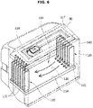
- FIG. 6 illustrates an inside of the ice bucket of the refrigerator of FIG. 1
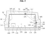
- FIG. 7 is a plane view of the ice bucket of the refrigerator of FIG. 1 .
- the ice bucket 110 includes a spacing member 130 provided such that the circulation of cool air may easily occur as the cool air is output through the cool air outlet 118 to an outside after the cool air is input through the cool air inlet 117 to the ice storage space 120.
- the spacing member 130 may be capable of having the circulation of cool air easily occur by allowing a flow path of the cool air in between ice and the ice bucket body by spacing the ice stored at the ice storage space 120 of the ice bucket 110 apart from the ice bucket body toward the ice storage space 120.
- the spacing member 130 has adequate strength not to be broken or separated by a collision with ice.
- the spacing member 130 is integrally formed with the ice bucket 110.
- the spacing member 130 may be formed with an identical material of the ice bucket 110.
- the spacing member 130 includes a plurality of guide ribs 131 extendedly formed in lengthways in vertical directions at the right side wall 113 and the left side wall 112 of the ice bucket 110 that are adjacent to the cool air inlet 117 and the cool air outlet 118 of the ice bucket 110, respectively.
- the plurality of guide ribs 131 spaces ice from the right side wall 113 apart from and the left side wall 112.
- the plurality of guide ribs 131 are extended in vertical direction and may guide the cool air inlet through the cool air inlet 117 to the ice storage space 120 toward a lower direction, and may guide the cool air being outlet through the cool air outlet 118 to an outside toward an upper direction.
- the adjacent ribs from the plurality of guide ribs 131 are provided to be spaced apart to each other by a predetermined gap as to form a flow path of cool air in between the adjacent guide ribs 131.
- the guide rib 131 is bar shaped, but the shape of the guide rib 131 is not limited, and may be provided with a partially bent shape or a curved shape. According to an exemplary embodiment, the guide rib 131 may be provided to be approximately perpendicular to a wall or bottom surface, but is not limited hereto, and, the guide rib 131 may be inclinedly provided in some degree.
- the plurality of guide ribs 131 are provided at the right side wall 113 and the left side wall 112 of the ice bucket 110, respectively.
- the positions of the cool air inlet 117 and the cool air outlet 118 of the ice bucket 110, the positions of the plurality of guide ribs 131 as well may be changed.
- the refrigerator 1 in accordance with an embodiment of the present disclosure may include an ice level detecting sensor, e.g., a full-ice detecting sensor 150 to detect the ice level status, e.g., the full-ice status at the ice bucket 110.
- the full-ice detecting sensor 150 may be an optical sensor having an emitter to radiate optical signals including infrared light, and a receiver to receive the optical signals radiated from the emitter and output the value of the received optical signals.
- the terminology referred to as the full-ice detecting sensor 150 will used as a terminology referring to the both of the emitter and the receiver, or one of the emitter and the receiver.
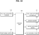
- the refrigerator may include a control unit 200 (see, for example, FIG. 10 ) to control a driving of an ice-making cycle having a supplying of water to supply water to the ice making device 80, a making of ice to cool the ice making device 80, a moving of ice to move the ice generated at the ice making device 80 to the ice bucket 110, and a determining of full-ice status to determine the full-ice status at the ice bucket 110.
- a control unit 200 see, for example, FIG. 10 to control a driving of an ice-making cycle having a supplying of water to supply water to the ice making device 80, a making of ice to cool the ice making device 80, a moving of ice to move the ice generated at the ice making device 80 to the ice bucket 110, and a determining of full-ice status to determine the full-ice status at the ice bucket 110.
- the control unit 200 may determine that the ice bucket 110 is full of ice when the value output at the full-ice detecting sensor 150 is less than a predetermined reference value. As an example, when the output value is less than 1 V, the ice bucket 110 may be determined to be full with ice.
- the control unit 200 may finish the ice-making cycle upon determining that the ice bucket 110 is full with ice. When determining that the ice bucket 110 is not full with ice, the control unit 200 may repeatedly continue the ice-making cycle.
- a method of determining the full-ice status by the control unit 200 is described.
- the full-ice detecting sensor 150 may be installed at the ice storage compartment 90 to detect the full-ice status at the ice bucket 110.
- the full-ice detecting sensor 150 may be embedded at the left side wall 93 and the rear wall 95 of the ice storage compartment 90.
- the full-ice detecting sensor 150 may be provided to be positioned at an outside the ice bucket 110. Therefore, the ice bucket 110 and the full-ice detecting sensor 150 may not be disturbed during mounting or dismounting the ice bucket 110 at the ice storage compartment 90.
- a mounting groove 105 at which the full-ice detecting sensor 150 may be mounted may be formed at the each of the left side wall 93 and the rear wall 95 of the ice storage compartment 90, and the full-ice detecting sensor 150 may be accommodated at the mounting groove 105.
- a diagonal path may be formed.
- the optical path in between the emitter and the receiver may be provided to be a diagonal path, the optical path may be minimized within the limit in which the full-ice status is detected.
- the full-ice detecting sensor 150 may be provided at the each of the left side wall 93 and the right side wall 92 of the ice storage compartment 90, or may be provided at each of the right side wall 92 and the rear wall 95 of the ice storage compartment 90.
- the ice bucket 110 may be provided with an optical hole 125 formed thereto so that the optical signals transmitted/received at the full-ice detecting sensor 150 may be passed through an inside the ice bucket 110.
- the optical hole 125 may be formed at the each of the right side wall 113 and the rear wall 115 of the ice bucket 110 to correspond to the position of the full-ice detecting sensor 150.
- the full-ice detecting sensor 150 may be installed at an adjacent position with respect to the ice bucket 110, and as the full-ice detecting sensor 150 may be stably fixed even when the ice bucket 110 is mounted and dismounted, the reliability in detecting the full-ice status may be increased, and the durability of the full-ice detecting sensor 150 may be increased.
- a sensor heater 160 may radiate heat to defrost the full-ice detecting sensor 150.
- FIG. 8 illustrates a spacing member in accordance with an embodiment of the present disclosure
- FIG. 9 illustrates a spacing member in accordance with still an embodiment of the present disclosure.
- FIG. 8 and FIG. 9 different embodiments of a spacing member are described. With respect to the identical structure to the embodiments described previously, the same numeric figures will be designated while descriptions may be omitted.
- a spacing member 132 includes a plurality of guide ribs 133 extendedly formed lengthways in a vertical direction at both side walls of the ice bucket 110 that are adjacent to the cool air inlet 117 and the cool air outlet 118 of the ice bucket 110, and may include a dividing wall 134 formed at an inner side of the plurality of guide ribs 133.
- the plurality of guide ribs 133 spaces apart ice from both the side walls of the ice bucket 110.
- the plurality of guide ribs 133 are extended in vertical directions, and may guide the cool air inlet to the ice storage space 120 through the cool air inlet 117 toward a lower direction, and may guide the cool air outlet to an outside though the cool air outlet 118 toward an upper direction.
- the adjacent guide ribs 133 from the plurality of guide ribs 133 form a cool air flow path in between the adjacent guide ribs 133 while spaced apart from each other by a predetermined space.
- the dividing wall 134 may divide the ice storage space 120 of the ice bucket 110 into an outside cool air flow path domain and an inside ice storage domain.
- the dividing wall 134 may be formed in the shape of a plate.
- the dividing wall 134 may be perpendicularly provided with respect to the guide rib 133.
- the dividing wall 134 may be provided with a cool air communicating hole 135 such that cool air may be communicated after penetrating through the dividing wall 134.
- the plurality of guide ribs 133 and the dividing wall 134 may be integrally formed to each other, or may be coupled to each other while provided separately.
- a spacing member 136 may include a plurality of guide ribs 137 extendedly formed lengthways toward horizontal directions at the bottom 114 of the ice bucket 110.
- the plurality of guide ribs 137 may be extended lengthways in a direction from the cool air inlet 117 of the ice bucket 110 in a direction towards the cool air outlet 118 of the ice bucket 110.
- the plurality of guide ribs 137 may space apart ice from the bottom 114 of the ice bucket 110, and may guide the cool air inlet to the cool air inlet 117 of the ice bucket 110 to the cool air outlet 118 of the ice bucket 110.
- the adjacent guide ribs 137 from the plurality of guide ribs 137 may form a cool air flow path in between the adjacent guide ribs 137 while spaced apart from each other by a predetermined space.
- FIG. 10 is a block diagram to describe an exemplary ice-making process of the present disclosure
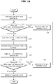
- FIG. 11 illustrates detecting a full-ice status in accordance with an embodiment of the present disclosure
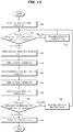
- FIG. 12 illustrates detecting a full-ice status in accordance with an embodiment of the present disclosure.
- the control unit 200 may control proceeding and finishing of an ice-making cycle including a determining of a full-ice status at the ice bucket 110 by use of a delivered output value of the optical signals that are received from the full-ice detecting sensor 150, a supplying of water, a making of ice, a moving of ice, and a detecting of the full-ice status depending on the full-ice status at the ice bucket 110.
- the control unit 200 may control a proceeding of an ice-making cycle after determining that the ice at the ice bucket 110 is output according to the motion of the dispensing switch 38 of the dispenser 34.
- the control unit 200 may supply water to the ice making device 80 by controlling a water supplying device 170, cool the ice making device 80 by controlling the cool air supplying apparatus 23, and move ice from the ice making device 80 by rotating the scraper through controlling the ice-moving apparatus 81.
- the control unit 200 may heat the full-ice detecting sensor 150 by controlling the sensor heater 160.
- control unit 200 may be provided to standby for a predetermined standby time T after the first determination on the full-ice status at the ice bucket 110 is made (220), and may finally determine the full-ice status by performing a process of the second determination on the full-ice status at the ice bucket 110 (270).
- the control unit 200 is provided to turn the full-ice detecting sensor (210) on, and may proceed with the first determination on the full-ice status at the ice bucket 110 (220).
- the first determination on the full-ice status may be made by comparing the value of the optical signals output from the full-ice detecting sensor 150 and a predetermined reference value. As an example, when the value of the optical signals output from the full-ice detecting sensor 150 is greater than the predetermined reference value, a determination may be made that the full-ice status is not reached, and when the value of the optical signals output from the full-ice detecting sensor 150 is less than the predetermined reference value, a determination may be made that the full-ice status is reached.
- control unit 200 When determined that the full-ice status is not reached after the first determination on the full-ice status is proceeded, the control unit 200 is provided to proceed again with the ice-making cycle including the supplying of water, the making of ice, the moving of ice, and the detecting of full-ice status to store ice at the ice bucket 110 (230), and is provided to proceed again with the process of the first determination on the full-ice status.
- the control unit 200 When determined that the full-ice status is reached after proceeding with the first determination on the full-ice status, the control unit 200 turns the full-ice detecting sensor (240) off, and the ice-making cycle to standby during the predetermined standby time T. That is, the control unit 200, even when it is determined that the full-ice status is reached after proceeding with the first determination on the full-ice status, standbys during the predetermined standby time T (250) without immediately finishing the ice-making cycle.
- an error is prevented, for example, in a determination of a full-ice status of the ice bucket 110.
- ice may further be stored.
- the ice at the uppermost position in the ice bucket 110 may momentarily disturb the optical signals, so that a determination may be erroneously made that the full-ice status is reached, while the actual status may not be an actual full-ice status.
- the control unit 200 when the predetermined standby time T is elapsed, may turn the full-ice detecting sensor 150 on (260) to proceed with the second determination of the full-ice status (270).
- the ice-making cycle proceed again (280), and the process of the first determination on the full-ice status again proceeds (220).
- the ice-making cycle is finished (290).
- the control unit 200 in accordance with an embodiment of the present disclosure may be provided to standby for a predetermined standby time T after the first determination is made that the full-ice status is reached at the ice bucket 110 (320), and may finally determine the full-ice status by performing a process of the second determination on the full-ice status at the ice bucket 110 (390).
- the frost at the full-ice detecting sensor 150 may be removed by turning ON/OFF the sensor heater 160 (see, for example, FIG. 7 ) in between the time when the first determination is made that the full-ice status is reached at the ice bucket 110 (320) and when the second determination is made that the full-ice status is reached at the ice bucket 110 (390).
- control unit 200 may be provided to turn the full-ice detecting sensor on (310), and may proceed with the first determination on the full-ice status at the ice bucket 110 (320).
- the first determination on the full-ice status may occur by comparing the value of the optical signals output from the full-ice detecting sensor 150 and a predetermined reference value. As an example, when the value of the optical signals output from the full-ice detecting sensor 150 is greater than the predetermined reference value, a determination may be made that the full-ice status is not reached, and when the value of the optical signals output from the full-ice detecting sensor 150 is less than the predetermined reference value, a determination may be made that the full-ice status is reached.
- control unit 200 may proceed again with the ice-making cycle including the supplying of water, the making of ice, the moving of ice, and the detecting of full-ice status to store ice at the ice bucket 110 (330), and proceed again with the process of the first determination on the full-ice status.
- the control unit 200 may turn the full-ice detecting sensor off (340), turn the sensor heater 160 on (350), and the ice-making cycle to standby during the predetermined standby time T (360). That is, the control unit 200, even when it is determined that the full-ice status is reached after proceeding with the first determination on the full-ice status, may standby during the predetermined standby time T without immediately finishing the ice-making cycle.
- the full-ice detecting sensor 150 may be heated by driving the sensor heater 160 as to eliminate a possibility of error, which may be caused by frost at the full-ice detecting sensor 150, in detecting the full-ice status.
- the control unit 200 when the predetermined standby time T is elapsed, turn the sensor heater 160 off (370) to proceed with the second determination on the full-ice status (390).
- the ice-making cycle again proceeds (400), and the process of the first determination on the full-ice status is proceeded again (320).
- the ice-making cycle is finished (410).
- a circulation of cool air at an inside an ice bucket can easily occur.
- reliability of a full-ice detecting structure including a full-ice detecting sensor having an emitter to radiate optical signals and a receiver to receive optical signals can be increased.
Landscapes
- Engineering & Computer Science (AREA)
- Physics & Mathematics (AREA)
- Mechanical Engineering (AREA)
- Thermal Sciences (AREA)
- General Engineering & Computer Science (AREA)
- Chemical & Material Sciences (AREA)
- Combustion & Propulsion (AREA)
- Cold Air Circulating Systems And Constructional Details In Refrigerators (AREA)
- Devices That Are Associated With Refrigeration Equipment (AREA)
- Production, Working, Storing, Or Distribution Of Ice (AREA)
Claims (5)
- Réfrigérateur comprenant :un corps (10) ayant un compartiment de stockage (21, 22) ;un dispositif de production de glace (80) pour générer de la glace ; etun seau à glace (110) pour stocker la glace générée au niveau du dispositif de production de glace (80),dans lequel le seau à glace (110) comprend :un corps de seau à glace,un espace de stockage de glace (120) formé dans un intérieur du corps de seau à glace, etune pluralité de nervures de guidage allongées (131, 133, 137) qui permettent à la glace d'être espacée du corps de seau à glace en direction de l'espace de stockage de glace (120) afin de permettre un trajet d'écoulement d'air frais,dans lequel la pluralité de nervures de guidage (131, 133, 137) est prévue d'un seul tenant avec le corps de seau à glace, dépasse du corps de seau à glace en direction de l'espace de stockage de glace et s'étend verticalement au niveau des deux parois latérales du corps de seau à glace, etcaractérisé en ce que
les nervures de guidage (131, 133, 137) adjacentes les unes aux autres parmi la pluralité de nervures de guidage (131, 133, 137) forment un trajet d'écoulement d'air frais entre les nervures de guidage adjacentes tout en étant espacées les unes des autres d'un écart prédéterminé. - Réfrigérateur selon la revendication 1, dans lequel :
la pluralité de nervures de guidage (131, 133, 137) comprend une paroi de division (134) formée en s'étendant au niveau de faces internes de la pluralité de nervures de guidage (131, 133, 137) pour diviser le trajet d'écoulement d'air frais. - Réfrigérateur selon la revendication 2, dans lequel :
un trou de communication d'air frais (135) est formé au niveau de la paroi de division (134) pour avoir de l'air frais communiqué après que l'air frais a pénétré à travers la paroi de division (134). - Réfrigérateur selon l'une quelconque des revendications précédentes, dans lequel :
le seau à glace (110) comprend une entrée d'air frais (117) et une sortie d'air frais (118) formées l'une et l'autre au niveau d'une paroi supérieure (111) du seau à glace (110) afin d'avoir de l'air frais introduit et évacué. - Réfrigérateur selon la revendication 4, dans lequel :
l'entrée d'air frais (117) est formée adjacente à une paroi latérale (112, 113) du seau à glace (110), et la sortie d'air frais (118) est formée adjacente à une paroi latérale (112, 113) opposée du seau à glace (110).
Priority Applications (1)
| Application Number | Priority Date | Filing Date | Title |
|---|---|---|---|
| EP18186038.8A EP3410044B1 (fr) | 2014-08-22 | 2015-08-20 | Réfrigérateur |
Applications Claiming Priority (1)
| Application Number | Priority Date | Filing Date | Title |
|---|---|---|---|
| KR1020140109445A KR102279393B1 (ko) | 2014-08-22 | 2014-08-22 | 냉장고 |
Related Child Applications (2)
| Application Number | Title | Priority Date | Filing Date |
|---|---|---|---|
| EP18186038.8A Division EP3410044B1 (fr) | 2014-08-22 | 2015-08-20 | Réfrigérateur |
| EP18186038.8A Division-Into EP3410044B1 (fr) | 2014-08-22 | 2015-08-20 | Réfrigérateur |
Publications (3)
| Publication Number | Publication Date |
|---|---|
| EP2988079A2 EP2988079A2 (fr) | 2016-02-24 |
| EP2988079A3 EP2988079A3 (fr) | 2016-06-01 |
| EP2988079B1 true EP2988079B1 (fr) | 2018-10-03 |
Family
ID=54011560
Family Applications (2)
| Application Number | Title | Priority Date | Filing Date |
|---|---|---|---|
| EP15181722.8A Active EP2988079B1 (fr) | 2014-08-22 | 2015-08-20 | Réfrigérateur |
| EP18186038.8A Active EP3410044B1 (fr) | 2014-08-22 | 2015-08-20 | Réfrigérateur |
Family Applications After (1)
| Application Number | Title | Priority Date | Filing Date |
|---|---|---|---|
| EP18186038.8A Active EP3410044B1 (fr) | 2014-08-22 | 2015-08-20 | Réfrigérateur |
Country Status (4)
| Country | Link |
|---|---|
| US (2) | US10495366B2 (fr) |
| EP (2) | EP2988079B1 (fr) |
| KR (1) | KR102279393B1 (fr) |
| CN (1) | CN105371551B (fr) |
Families Citing this family (24)
| Publication number | Priority date | Publication date | Assignee | Title |
|---|---|---|---|---|
| US9314823B2 (en) | 2011-06-29 | 2016-04-19 | Minesense Technologies Ltd. | High capacity cascade-type mineral sorting machine and method |
| US11219927B2 (en) | 2011-06-29 | 2022-01-11 | Minesense Technologies Ltd. | Sorting materials using pattern recognition, such as upgrading nickel laterite ores through electromagnetic sensor-based methods |
| AU2012277493B2 (en) | 2011-06-29 | 2017-04-27 | Minesense Technologies Ltd. | Extracting mined ore, minerals or other materials using sensor-based sorting |
| CN110090812B (zh) | 2014-07-21 | 2021-07-09 | 感矿科技有限公司 | 来自废物矿物的粗矿石矿物的高容量分离 |
| US9522415B2 (en) * | 2014-07-21 | 2016-12-20 | Minesense Technologies Ltd. | Mining shovel with compositional sensors |
| CN106679256B (zh) * | 2016-12-21 | 2019-08-27 | 合肥华凌股份有限公司 | 制冰机及具有其的冰箱 |
| KR20180075124A (ko) * | 2016-12-26 | 2018-07-04 | 엘지전자 주식회사 | 정수기의 제어 방법 |
| KR102338471B1 (ko) * | 2016-12-29 | 2021-12-14 | 삼성전자주식회사 | 냉장고 |
| US10775088B2 (en) * | 2018-02-16 | 2020-09-15 | Haier Us Appliance Solutions, Inc. | Ice making assembly coupling |
| US11525621B2 (en) | 2018-03-12 | 2022-12-13 | Whirlpool Corporation | Anti-rolling icebox gasket for refrigerator swing doors |
| KR102496329B1 (ko) * | 2018-03-30 | 2023-02-07 | 삼성전자주식회사 | 냉장고 |
| US11480377B2 (en) * | 2018-11-16 | 2022-10-25 | Lg Electronics Inc. | Refrigerator |
| TR201913340A2 (tr) * | 2019-09-04 | 2021-03-22 | Bsh Ev Aletleri San Ve Tic As | Hava-yönlendi̇rme kanalina sahi̇p bi̇r ev ci̇hazi kapisi |
| US20210123652A1 (en) * | 2019-10-28 | 2021-04-29 | Haier Us Appliance Solutions, Inc. | Sensor assembly for detecting the level of ice within an ice making appliance |
| US11255589B2 (en) | 2020-01-18 | 2022-02-22 | True Manufacturing Co., Inc. | Ice maker |
| US11391500B2 (en) | 2020-01-18 | 2022-07-19 | True Manufacturing Co., Inc. | Ice maker |
| US11578905B2 (en) | 2020-01-18 | 2023-02-14 | True Manufacturing Co., Inc. | Ice maker, ice dispensing assembly, and method of deploying ice maker |
| US11656017B2 (en) | 2020-01-18 | 2023-05-23 | True Manufacturing Co., Inc. | Ice maker |
| US11602059B2 (en) | 2020-01-18 | 2023-03-07 | True Manufacturing Co., Inc. | Refrigeration appliance with detachable electronics module |
| US11913699B2 (en) | 2020-01-18 | 2024-02-27 | True Manufacturing Co., Inc. | Ice maker |
| US11802727B2 (en) | 2020-01-18 | 2023-10-31 | True Manufacturing Co., Inc. | Ice maker |
| US11519652B2 (en) | 2020-03-18 | 2022-12-06 | True Manufacturing Co., Inc. | Ice maker |
| US11674731B2 (en) | 2021-01-13 | 2023-06-13 | True Manufacturing Co., Inc. | Ice maker |
| US11686519B2 (en) | 2021-07-19 | 2023-06-27 | True Manufacturing Co., Inc. | Ice maker with pulsed fill routine |
Citations (3)
| Publication number | Priority date | Publication date | Assignee | Title |
|---|---|---|---|---|
| US20080034780A1 (en) * | 2006-08-11 | 2008-02-14 | Samsung Electronics Co., Ltd. | Ice making apparatus and refrigerator having the same |
| EP2239528A1 (fr) * | 2009-03-30 | 2010-10-13 | Fagor, S. Coop. | Récipient pour un dispositif de refroidissement |
| US20130167576A1 (en) * | 2012-01-03 | 2013-07-04 | Lg Electronics Inc. | Refrigerator |
Family Cites Families (128)
| Publication number | Priority date | Publication date | Assignee | Title |
|---|---|---|---|---|
| JPS5434171U (fr) * | 1977-08-10 | 1979-03-06 | ||
| JPS5434171A (en) | 1977-08-23 | 1979-03-13 | Fuji Electric Co Ltd | Flat type freezing and refrigerating open show case |
| US4344295A (en) * | 1981-01-22 | 1982-08-17 | Whirlpool Corporation | Control for timed operation of ice maker |
| ATE29829T1 (de) | 1982-01-19 | 1987-10-15 | Invicta Plastics Ltd | Eiskuebel. |
| US4424683A (en) * | 1982-09-27 | 1984-01-10 | Whirlpool Corporation | Ice maker control |
| US4475357A (en) * | 1982-09-27 | 1984-10-09 | Whirlpool Corporation | Ice production rate selector for ice maker |
| US4774814A (en) * | 1986-09-05 | 1988-10-04 | Mile High Equipment Company | Ice making machine |
| US4733539A (en) * | 1986-12-04 | 1988-03-29 | Schneider Metal Manufacturing Co. | Ice cube maker with new freeze and harvest control |
| US4938030A (en) * | 1986-12-04 | 1990-07-03 | Schneider Metal Manufacturing Co. | Ice cube maker with new freeze and harvest control |
| US5056325A (en) * | 1986-12-04 | 1991-10-15 | The Cornelius Company | Ice cube maker with new freeze and harvest control |
| US4756165A (en) * | 1987-08-03 | 1988-07-12 | Whirlpool Corporation | Single revolution ice maker |
| US4799362A (en) * | 1987-12-21 | 1989-01-24 | Whirlpool Corporation | Modular home ice maker test apparatus |
| US4872317A (en) * | 1988-10-24 | 1989-10-10 | U-Line Corporation | Unitary ice maker with fresh food compartment and control system therefor |
| US5129237A (en) * | 1989-06-26 | 1992-07-14 | Servend International, Inc. | Ice making machine with freeze and harvest control |
| US4947653A (en) * | 1989-06-26 | 1990-08-14 | Hussmann Corporation | Ice making machine with freeze and harvest control |
| US5042263A (en) * | 1990-08-13 | 1991-08-27 | Servend International, Inc. | Ice making machine with freeze and harvest control |
| US5297394A (en) * | 1991-12-31 | 1994-03-29 | Whirlpool Corporation | Clear cube ice maker |
| US5187948A (en) * | 1991-12-31 | 1993-02-23 | Whirlpool Corporation | Clear cube ice maker |
| US5261248A (en) * | 1992-02-24 | 1993-11-16 | Whirlpool Corporation | Fill cup sleeve for a recoverable domestic icemaker |
| US5160094A (en) * | 1992-02-24 | 1992-11-03 | Whirlpool Corporation | Recoverable domestic ice maker |
| US5477694A (en) * | 1994-05-18 | 1995-12-26 | Scotsman Group, Inc. | Method for controlling an ice making machine and apparatus therefor |
| JPH08100977A (ja) * | 1994-09-30 | 1996-04-16 | Toshiba Corp | 冷蔵庫 |
| US5653114A (en) * | 1995-09-01 | 1997-08-05 | Nartron Corporation | Method and system for electronically controlling the location of the formation of ice within a closed loop water circulating unit |
| US5931003A (en) * | 1995-09-01 | 1999-08-03 | Natron Corporation | Method and system for electronically controlling the location of the formation of ice within a closed loop water circulating unit |
| US6282909B1 (en) * | 1995-09-01 | 2001-09-04 | Nartron Corporation | Ice making system, method, and component apparatus |
| KR0177738B1 (ko) * | 1996-06-10 | 1999-04-15 | 윤종용 | 자동제빙기의 이빙모드 제어방법 |
| US5829257A (en) * | 1997-03-31 | 1998-11-03 | Narton Corporation | Methods and systems for harvesting ice in an ice making apparatus |
| US5878583A (en) * | 1997-04-01 | 1999-03-09 | Manitowoc Foodservice Group, Inc. | Ice making machine and control method therefore |
| KR20000009946U (ko) * | 1998-11-13 | 2000-06-05 | 전주범 | 냉장고용 제빙가이드 |
| US6314745B1 (en) * | 1998-12-28 | 2001-11-13 | Whirlpool Corporation | Refrigerator having an ice maker and a control system therefor |
| US6286324B1 (en) * | 1998-12-28 | 2001-09-11 | Whirlpool Corporation | Ice level sensing system for an ice maker |
| US6425259B2 (en) * | 1998-12-28 | 2002-07-30 | Whirlpool Corporation | Removable ice bucket for an ice maker |
| US6526763B2 (en) * | 1999-04-02 | 2003-03-04 | Dekko Heating Technologies, Inc. | Ice maker and method of making ice |
| US6490873B2 (en) * | 1999-04-02 | 2002-12-10 | Dekko Heating Technologies, Inc. | Ice maker and method of making ice |
| US6257465B1 (en) * | 1999-11-05 | 2001-07-10 | Paul Treadwell | Ice dispenser |
| US6581391B2 (en) * | 2000-05-01 | 2003-06-24 | Technology Licensing Corporation | Ice thickness control system and sensor probe |
| US6351955B1 (en) * | 2000-07-31 | 2002-03-05 | Whirlpool Corporation | Method and apparatus for rapid ice production |
| US6405546B1 (en) * | 2000-08-16 | 2002-06-18 | Gregory M. Billman | Ice maker harvest control and method |
| US6463746B1 (en) * | 2000-09-27 | 2002-10-15 | Scotsman Ice Systems | Ice producing machine and method with gear motor monitoring |
| US6574974B1 (en) * | 2000-10-02 | 2003-06-10 | General Electric Company | Icemaker electronic control methods and apparatus |
| US6637217B2 (en) * | 2000-12-30 | 2003-10-28 | Lg Electronics Inc. | Ice maker for refrigerator and control method thereof |
| KR100437388B1 (ko) * | 2001-08-14 | 2004-06-25 | 주식회사 엘지이아이 | 냉장고용 제빙기 및 검사방법 |
| KR100412948B1 (ko) * | 2001-11-20 | 2003-12-31 | 주식회사 엘지이아이 | 냉장고용 제빙기의 급수량 표시장치 및 방법 |
| US6581392B1 (en) * | 2002-02-01 | 2003-06-24 | Scotsman Ice Systems | Ice machine and method for control thereof |
| US6612118B2 (en) * | 2002-02-06 | 2003-09-02 | Imi Cornelius Inc. | Ice maker control |
| KR20050083744A (ko) * | 2002-10-10 | 2005-08-26 | 마일 하이 이큅먼트 씨오. | 원격 탐지되는 제빙기 |
| US7318323B2 (en) * | 2003-03-11 | 2008-01-15 | Matsushita Electric Industrial Co., Ltd. | Ice-making device |
| WO2004083971A2 (fr) * | 2003-03-13 | 2004-09-30 | Imi Cornelius Inc. | Systeme de commande de machine a glace |
| US6679073B1 (en) * | 2003-03-14 | 2004-01-20 | General Electric Company | Refrigerator and ice maker methods and apparatus |
| US7062936B2 (en) * | 2003-11-21 | 2006-06-20 | U-Line Corporation | Clear ice making refrigerator |
| US6952936B2 (en) * | 2003-12-22 | 2005-10-11 | General Electric Company | Refrigerator and ice maker apparatus |
| JP2005188761A (ja) * | 2003-12-24 | 2005-07-14 | Matsushita Electric Ind Co Ltd | 自動製氷装置 |
| KR100584273B1 (ko) * | 2004-04-06 | 2006-05-26 | 엘지전자 주식회사 | 도어 제빙실의 냉기 유로 구조 |
| JP4231826B2 (ja) | 2004-08-20 | 2009-03-04 | ヤンマー株式会社 | 冷凍コンテナ |
| US7131280B2 (en) * | 2004-10-26 | 2006-11-07 | Whirlpool Corporation | Method for making ice in a compact ice maker |
| US7185508B2 (en) * | 2004-10-26 | 2007-03-06 | Whirlpool Corporation | Refrigerator with compact icemaker |
| KR100642362B1 (ko) * | 2004-11-02 | 2006-11-03 | 엘지전자 주식회사 | 제빙기의 급수량 제어장치 및 제어방법 |
| ES2719450T3 (es) * | 2005-02-01 | 2019-07-10 | Lg Electronics Inc | Refrigerador |
| US7143588B2 (en) * | 2005-03-14 | 2006-12-05 | Emerson Electric Co. | System and method for controlling ice tray fill in an ice maker |
| US7216491B2 (en) * | 2005-04-29 | 2007-05-15 | Emerson Electric Co | Ice maker with adaptive fill |
| US20060276932A1 (en) * | 2005-05-19 | 2006-12-07 | Scotsman Ice Systems | Ice-making machinery with lockout and method |
| US7281386B2 (en) * | 2005-06-14 | 2007-10-16 | Manitowoc Foodservice Companies, Inc. | Residential ice machine |
| KR20070042020A (ko) * | 2005-10-17 | 2007-04-20 | 삼성전자주식회사 | 냉장고 |
| KR100755404B1 (ko) * | 2006-08-11 | 2007-09-04 | 엘지전자 주식회사 | 냉장고의 제어방법 |
| AU2007293834B2 (en) * | 2006-09-04 | 2010-05-20 | Lg Electronics Inc. | Control apparatus for taking out ice of refrigerator and method thereof |
| US20080072610A1 (en) * | 2006-09-26 | 2008-03-27 | General Electric Company | Apparatus and method for controlling operation of an icemaker |
| US20080092567A1 (en) * | 2006-10-20 | 2008-04-24 | Doberstein Andrew J | Ice maker with ice bin level control |
| US20080092574A1 (en) * | 2006-10-20 | 2008-04-24 | Doberstein Andrew J | Cooler with multi-parameter cube ice maker control |
| US7743801B2 (en) * | 2006-12-29 | 2010-06-29 | General Electric Company | Method and system for dispensing ice and/or a liquid |
| US8820100B2 (en) * | 2006-12-29 | 2014-09-02 | Whirlpool Corporation | Apparatus, method, and system for automatically turning off an actuator in a refrigeration device upon detection of an unwanted condition |
| DE202007004580U1 (de) | 2007-03-26 | 2007-06-14 | Zippy Technology Corp. | Eiswürfelmaschine mit einem Konvektionslüfter |
| KR100809749B1 (ko) * | 2007-03-28 | 2008-03-04 | 엘지전자 주식회사 | 냉장고의 아이스메이커 어셈블리 |
| KR101406187B1 (ko) * | 2007-06-04 | 2014-06-13 | 삼성전자주식회사 | 제빙기 및 이를 갖는 냉장고 |
| CN102997549B (zh) * | 2007-11-05 | 2015-01-28 | Lg电子株式会社 | 冰箱 |
| WO2009078996A1 (fr) * | 2007-12-17 | 2009-06-25 | Mile High Equipment Llc | Machine de fabrication de glace pourvue d'un detecteur d'ecoulement d'eau |
| US7841192B2 (en) * | 2007-12-27 | 2010-11-30 | General Electric Company | Ice in bucket detection for an icemaker |
| US8522571B2 (en) | 2008-02-19 | 2013-09-03 | Whirlpool Corporation | Variable capacity ice storage assembly |
| US8109112B2 (en) * | 2008-02-25 | 2012-02-07 | Whirlpool Corporation | Variable ice storage assembly and method of use |
| US20100139299A1 (en) * | 2008-04-15 | 2010-06-10 | Dong-Hoon Lee | Refrigerator and full ice level sensing apparatus thereof |
| KR101474439B1 (ko) * | 2008-05-27 | 2014-12-19 | 엘지전자 주식회사 | 냉장고 제빙기의 만빙 감지 장치의 센서 히터 제어 방법 |
| KR101456572B1 (ko) * | 2008-05-27 | 2014-10-31 | 엘지전자 주식회사 | 냉장고 제빙기의 만빙 감지 장치의 센서 히터 제어 방법 |
| KR101456571B1 (ko) * | 2008-05-01 | 2014-10-31 | 엘지전자 주식회사 | 냉장고 제빙기의 만빙 감지 장치 및 그 만빙 감지 방법 |
| KR101451659B1 (ko) * | 2008-04-15 | 2014-10-16 | 엘지전자 주식회사 | 냉장고 제빙기의 만빙 감지 장치 |
| KR101451658B1 (ko) | 2008-04-15 | 2014-10-16 | 엘지전자 주식회사 | 냉장고 제빙기의 만빙 감지 장치 |
| US20090308085A1 (en) * | 2008-06-12 | 2009-12-17 | General Electric Company | Rotating icemaker assembly |
| US20110023510A1 (en) * | 2008-08-04 | 2011-02-03 | Lg Electronics Inc. | Ice maker and refrigerator having the same |
| KR20100040160A (ko) * | 2008-10-09 | 2010-04-19 | 삼성전자주식회사 | 냉장고 및 그 제어방법 |
| KR101622595B1 (ko) * | 2008-11-19 | 2016-05-19 | 엘지전자 주식회사 | 제빙장치 및 이를 구비한 냉장고 및 이 냉장고의 제빙방법 |
| JP2010169322A (ja) * | 2009-01-23 | 2010-08-05 | Mitsubishi Electric Corp | シャーベット氷製造システム、シャーベット氷の氷量測定装置及びシャーベット氷の氷量測定方法 |
| US8978406B2 (en) * | 2009-02-28 | 2015-03-17 | Electrolux Home Products, Inc. | Refrigeration apparatus for refrigeration appliance and method of minimizing frost accumulation |
| KR101658667B1 (ko) * | 2009-04-13 | 2016-09-21 | 엘지전자 주식회사 | 냉장고 |
| KR20100133155A (ko) * | 2009-06-11 | 2010-12-21 | 엘지전자 주식회사 | 제빙장치를 구비하는 냉장고 |
| US8424323B2 (en) * | 2009-11-13 | 2013-04-23 | General Electric Company | Ice level sensing system |
| KR101639440B1 (ko) | 2009-12-22 | 2016-07-22 | 엘지전자 주식회사 | 냉장고 |
| US8769981B2 (en) * | 2009-12-22 | 2014-07-08 | Lg Electronics Inc. | Refrigerator with ice maker and ice level sensor |
| KR20110096672A (ko) * | 2010-02-23 | 2011-08-31 | 엘지전자 주식회사 | 냉장고의 아이스 뱅크 및 이를 포함하는 냉장고 |
| US8464543B2 (en) * | 2010-03-08 | 2013-06-18 | Whirlpool Corporation | Door mounted ice level detection device |
| KR101718019B1 (ko) * | 2010-07-01 | 2017-04-04 | 엘지전자 주식회사 | 제빙기용 절전 장치 및 제빙기의 절전 방법 |
| CN102346448B (zh) * | 2010-08-03 | 2014-11-12 | 曼尼托沃食品服务有限公司 | 用于通知制冰周期启动时延的低压控制 |
| US20120031126A1 (en) * | 2010-08-06 | 2012-02-09 | Manitowoc Foodservice Companies,Llc | Control system for an ice maker |
| US20120036872A1 (en) * | 2010-08-10 | 2012-02-16 | Brent Alden Junge | Method and apparatus for improving energy efficiency of an ice maker system |
| KR101821813B1 (ko) * | 2010-09-20 | 2018-03-09 | 엘지전자 주식회사 | 냉장고 |
| US9091473B2 (en) * | 2010-11-09 | 2015-07-28 | General Electric Company | Float-type ice making assembly and related refrigeration appliance |
| US9664430B2 (en) * | 2010-11-17 | 2017-05-30 | Haier Us Appliance Solutions, Inc. | Ice maker for dispensing soft ice and related refrigeration appliance |
| US20120125018A1 (en) * | 2010-11-19 | 2012-05-24 | General Electric Company | Ice dispenser system for a refrigeration appliance, refrigeration appliance, and method of making ice |
| WO2012074323A2 (fr) | 2010-12-02 | 2012-06-07 | 웅진코웨이주식회사 | Réserve de glaçons |
| KR101775403B1 (ko) * | 2011-01-10 | 2017-09-07 | 삼성전자주식회사 | 제빙장치 및 이를 갖는 냉장고 |
| WO2012106318A1 (fr) * | 2011-01-31 | 2012-08-09 | Manitowoc Foodservice Companies, Llc | Commande de congélation et de récolte avec mode de sécurité d'une machine à glaçons et procédé associé |
| US20120204592A1 (en) * | 2011-02-11 | 2012-08-16 | General Electric Company | Ice dispenser for dispensing cubed and crushed ice and related refrigeration appliance |
| US9316427B2 (en) * | 2011-03-02 | 2016-04-19 | Whirlpool Corporation | Direct contact icemaker with chambered air cooling system |
| US8640488B2 (en) * | 2011-05-31 | 2014-02-04 | General Electric Company | Ice bin assembly |
| US8813509B2 (en) * | 2011-06-02 | 2014-08-26 | General Electric Company | Ice making assembly with optimized harvesting and related refrigeration appliance |
| US8844314B2 (en) * | 2011-06-22 | 2014-09-30 | Whirlpool Corporation | Clear ice making system and method |
| US9004115B2 (en) * | 2011-06-30 | 2015-04-14 | General Electric Company | Method and system for dispensing ice and/or a liquid |
| KR101913423B1 (ko) | 2011-09-09 | 2018-12-31 | 엘지전자 주식회사 | 냉장고 |
| KR101392927B1 (ko) * | 2011-10-17 | 2014-05-14 | 포항공과대학교 산학협력단 | 얼음엉김 해제기능을 갖는 아이스버킷 및 이를 구비한 냉장고 |
| KR101907166B1 (ko) * | 2011-12-30 | 2018-10-15 | 삼성전자주식회사 | 냉장고 |
| KR20130078530A (ko) * | 2011-12-30 | 2013-07-10 | 삼성전자주식회사 | 냉장고 |
| KR20130078531A (ko) * | 2011-12-30 | 2013-07-10 | 삼성전자주식회사 | 냉장고 |
| KR101513876B1 (ko) * | 2012-01-06 | 2015-04-21 | 삼성전자 주식회사 | 냉장고 |
| KR101980540B1 (ko) * | 2012-01-06 | 2019-05-21 | 삼성전자주식회사 | 냉장고 |
| KR101907167B1 (ko) | 2012-04-10 | 2018-10-12 | 삼성전자주식회사 | 냉장고 |
| US10119742B2 (en) * | 2012-05-18 | 2018-11-06 | Whirlpool Corporation | Flat top modular cooling system ice and air delivery |
| WO2013183890A1 (fr) * | 2012-06-07 | 2013-12-12 | Samsung Electronics Co., Ltd. | Réfrigérateur |
| US8857198B2 (en) * | 2012-06-08 | 2014-10-14 | General Electric Company | Icemaker shut off method for premature harvest reduction |
| KR101376873B1 (ko) * | 2012-07-10 | 2014-03-20 | 엘지전자 주식회사 | 냉장고 |
| US20140196478A1 (en) * | 2013-01-14 | 2014-07-17 | General Electric Company | Method for operating a refrigerator appliance ice maker |
| US9644879B2 (en) * | 2013-01-29 | 2017-05-09 | True Manufacturing Company, Inc. | Apparatus and method for sensing ice thickness and detecting failure modes of an ice maker |
-
2014
- 2014-08-22 KR KR1020140109445A patent/KR102279393B1/ko active IP Right Grant
-
2015
- 2015-07-30 US US14/813,539 patent/US10495366B2/en active Active
- 2015-08-20 EP EP15181722.8A patent/EP2988079B1/fr active Active
- 2015-08-20 EP EP18186038.8A patent/EP3410044B1/fr active Active
- 2015-08-21 CN CN201510520936.1A patent/CN105371551B/zh active Active
-
2019
- 2019-10-21 US US16/658,730 patent/US11378322B2/en active Active
Patent Citations (3)
| Publication number | Priority date | Publication date | Assignee | Title |
|---|---|---|---|---|
| US20080034780A1 (en) * | 2006-08-11 | 2008-02-14 | Samsung Electronics Co., Ltd. | Ice making apparatus and refrigerator having the same |
| EP2239528A1 (fr) * | 2009-03-30 | 2010-10-13 | Fagor, S. Coop. | Récipient pour un dispositif de refroidissement |
| US20130167576A1 (en) * | 2012-01-03 | 2013-07-04 | Lg Electronics Inc. | Refrigerator |
Also Published As
| Publication number | Publication date |
|---|---|
| EP3410044A3 (fr) | 2019-01-23 |
| US10495366B2 (en) | 2019-12-03 |
| US20160054044A1 (en) | 2016-02-25 |
| KR20160023282A (ko) | 2016-03-03 |
| US11378322B2 (en) | 2022-07-05 |
| EP3410044B1 (fr) | 2019-12-18 |
| EP2988079A3 (fr) | 2016-06-01 |
| KR102279393B1 (ko) | 2021-07-21 |
| CN105371551B (zh) | 2018-08-28 |
| US20200049396A1 (en) | 2020-02-13 |
| CN105371551A (zh) | 2016-03-02 |
| EP3410044A2 (fr) | 2018-12-05 |
| EP2988079A2 (fr) | 2016-02-24 |
Similar Documents
| Publication | Publication Date | Title |
|---|---|---|
| US11378322B2 (en) | Ice storage apparatus and method of use | |
| EP2988078B1 (fr) | Réfrigérateur | |
| US10634408B2 (en) | Refrigerator having a rotatable door for the ice making compartment forming the exterior appearance | |
| US8973391B2 (en) | Refrigerator | |
| US9080799B2 (en) | Refrigerator | |
| RU2552044C2 (ru) | Льдогенератор и холодильник с таким льдогенератором | |
| KR101658667B1 (ko) | 냉장고 | |
| KR101718995B1 (ko) | 냉장고 | |
| KR101665545B1 (ko) | 제빙유닛 및 이를 포함하는 냉장고 | |
| US20080072610A1 (en) | Apparatus and method for controlling operation of an icemaker | |
| KR101626614B1 (ko) | 냉장고의 제어 방법 | |
| KR20190103807A (ko) | 냉장고 및 냉장고의 제어 방법 | |
| KR101830513B1 (ko) | 냉장고 및 냉장고의 제어 방법 | |
| US9377235B2 (en) | Refrigerator and control method for the same | |
| KR20120100210A (ko) | 냉장고 제빙장치 및 그 제어방법 | |
| EP4004460B1 (fr) | Réfrigérateur | |
| EP3896368B1 (fr) | Réfrigérateur | |
| KR101626668B1 (ko) | 냉장고 | |
| KR101639440B1 (ko) | 냉장고 | |
| KR20090109420A (ko) | 냉장고 제빙기의 만빙 감지 장치 | |
| KR20100002901A (ko) | 제빙기의 제어 장치 및 그 방법 |
Legal Events
| Date | Code | Title | Description |
|---|---|---|---|
| PUAI | Public reference made under article 153(3) epc to a published international application that has entered the european phase |
Free format text: ORIGINAL CODE: 0009012 |
|
| 17P | Request for examination filed |
Effective date: 20150820 |
|
| AK | Designated contracting states |
Kind code of ref document: A2 Designated state(s): AL AT BE BG CH CY CZ DE DK EE ES FI FR GB GR HR HU IE IS IT LI LT LU LV MC MK MT NL NO PL PT RO RS SE SI SK SM TR |
|
| AX | Request for extension of the european patent |
Extension state: BA ME |
|
| PUAL | Search report despatched |
Free format text: ORIGINAL CODE: 0009013 |
|
| AK | Designated contracting states |
Kind code of ref document: A3 Designated state(s): AL AT BE BG CH CY CZ DE DK EE ES FI FR GB GR HR HU IE IS IT LI LT LU LV MC MK MT NL NO PL PT RO RS SE SI SK SM TR |
|
| AX | Request for extension of the european patent |
Extension state: BA ME |
|
| RIC1 | Information provided on ipc code assigned before grant |
Ipc: F25C 5/18 20060101ALI20160422BHEP Ipc: F25C 5/00 20060101AFI20160422BHEP |
|
| STAA | Information on the status of an ep patent application or granted ep patent |
Free format text: STATUS: EXAMINATION IS IN PROGRESS |
|
| 17Q | First examination report despatched |
Effective date: 20170614 |
|
| REG | Reference to a national code |
Ref country code: DE Ref legal event code: R079 Ref document number: 602015017387 Country of ref document: DE Free format text: PREVIOUS MAIN CLASS: F25C0005000000 Ipc: F25C0005182000 |
|
| GRAP | Despatch of communication of intention to grant a patent |
Free format text: ORIGINAL CODE: EPIDOSNIGR1 |
|
| STAA | Information on the status of an ep patent application or granted ep patent |
Free format text: STATUS: GRANT OF PATENT IS INTENDED |
|
| RIC1 | Information provided on ipc code assigned before grant |
Ipc: F25C 5/20 20180101ALI20180306BHEP Ipc: F25C 5/182 20180101AFI20180306BHEP Ipc: F25C 1/00 20060101ALI20180306BHEP Ipc: F25C 5/187 20180101ALI20180306BHEP |
|
| INTG | Intention to grant announced |
Effective date: 20180323 |
|
| GRAS | Grant fee paid |
Free format text: ORIGINAL CODE: EPIDOSNIGR3 |
|
| GRAA | (expected) grant |
Free format text: ORIGINAL CODE: 0009210 |
|
| STAA | Information on the status of an ep patent application or granted ep patent |
Free format text: STATUS: THE PATENT HAS BEEN GRANTED |
|
| AK | Designated contracting states |
Kind code of ref document: B1 Designated state(s): AL AT BE BG CH CY CZ DE DK EE ES FI FR GB GR HR HU IE IS IT LI LT LU LV MC MK MT NL NO PL PT RO RS SE SI SK SM TR |
|
| REG | Reference to a national code |
Ref country code: GB Ref legal event code: FG4D |
|
| REG | Reference to a national code |
Ref country code: CH Ref legal event code: EP Ref country code: AT Ref legal event code: REF Ref document number: 1049042 Country of ref document: AT Kind code of ref document: T Effective date: 20181015 |
|
| REG | Reference to a national code |
Ref country code: IE Ref legal event code: FG4D Ref country code: DE Ref legal event code: R096 Ref document number: 602015017387 Country of ref document: DE |
|
| REG | Reference to a national code |
Ref country code: NL Ref legal event code: MP Effective date: 20181003 |
|
| REG | Reference to a national code |
Ref country code: LT Ref legal event code: MG4D |
|
| REG | Reference to a national code |
Ref country code: AT Ref legal event code: MK05 Ref document number: 1049042 Country of ref document: AT Kind code of ref document: T Effective date: 20181003 |
|
| PG25 | Lapsed in a contracting state [announced via postgrant information from national office to epo] |
Ref country code: NL Free format text: LAPSE BECAUSE OF FAILURE TO SUBMIT A TRANSLATION OF THE DESCRIPTION OR TO PAY THE FEE WITHIN THE PRESCRIBED TIME-LIMIT Effective date: 20181003 |
|
| PG25 | Lapsed in a contracting state [announced via postgrant information from national office to epo] |
Ref country code: FI Free format text: LAPSE BECAUSE OF FAILURE TO SUBMIT A TRANSLATION OF THE DESCRIPTION OR TO PAY THE FEE WITHIN THE PRESCRIBED TIME-LIMIT Effective date: 20181003 Ref country code: IS Free format text: LAPSE BECAUSE OF FAILURE TO SUBMIT A TRANSLATION OF THE DESCRIPTION OR TO PAY THE FEE WITHIN THE PRESCRIBED TIME-LIMIT Effective date: 20190203 Ref country code: BG Free format text: LAPSE BECAUSE OF FAILURE TO SUBMIT A TRANSLATION OF THE DESCRIPTION OR TO PAY THE FEE WITHIN THE PRESCRIBED TIME-LIMIT Effective date: 20190103 Ref country code: PL Free format text: LAPSE BECAUSE OF FAILURE TO SUBMIT A TRANSLATION OF THE DESCRIPTION OR TO PAY THE FEE WITHIN THE PRESCRIBED TIME-LIMIT Effective date: 20181003 Ref country code: HR Free format text: LAPSE BECAUSE OF FAILURE TO SUBMIT A TRANSLATION OF THE DESCRIPTION OR TO PAY THE FEE WITHIN THE PRESCRIBED TIME-LIMIT Effective date: 20181003 Ref country code: CZ Free format text: LAPSE BECAUSE OF FAILURE TO SUBMIT A TRANSLATION OF THE DESCRIPTION OR TO PAY THE FEE WITHIN THE PRESCRIBED TIME-LIMIT Effective date: 20181003 Ref country code: NO Free format text: LAPSE BECAUSE OF FAILURE TO SUBMIT A TRANSLATION OF THE DESCRIPTION OR TO PAY THE FEE WITHIN THE PRESCRIBED TIME-LIMIT Effective date: 20190103 Ref country code: LT Free format text: LAPSE BECAUSE OF FAILURE TO SUBMIT A TRANSLATION OF THE DESCRIPTION OR TO PAY THE FEE WITHIN THE PRESCRIBED TIME-LIMIT Effective date: 20181003 Ref country code: ES Free format text: LAPSE BECAUSE OF FAILURE TO SUBMIT A TRANSLATION OF THE DESCRIPTION OR TO PAY THE FEE WITHIN THE PRESCRIBED TIME-LIMIT Effective date: 20181003 Ref country code: AT Free format text: LAPSE BECAUSE OF FAILURE TO SUBMIT A TRANSLATION OF THE DESCRIPTION OR TO PAY THE FEE WITHIN THE PRESCRIBED TIME-LIMIT Effective date: 20181003 Ref country code: LV Free format text: LAPSE BECAUSE OF FAILURE TO SUBMIT A TRANSLATION OF THE DESCRIPTION OR TO PAY THE FEE WITHIN THE PRESCRIBED TIME-LIMIT Effective date: 20181003 |
|
| PG25 | Lapsed in a contracting state [announced via postgrant information from national office to epo] |
Ref country code: AL Free format text: LAPSE BECAUSE OF FAILURE TO SUBMIT A TRANSLATION OF THE DESCRIPTION OR TO PAY THE FEE WITHIN THE PRESCRIBED TIME-LIMIT Effective date: 20181003 Ref country code: SE Free format text: LAPSE BECAUSE OF FAILURE TO SUBMIT A TRANSLATION OF THE DESCRIPTION OR TO PAY THE FEE WITHIN THE PRESCRIBED TIME-LIMIT Effective date: 20181003 Ref country code: RS Free format text: LAPSE BECAUSE OF FAILURE TO SUBMIT A TRANSLATION OF THE DESCRIPTION OR TO PAY THE FEE WITHIN THE PRESCRIBED TIME-LIMIT Effective date: 20181003 Ref country code: GR Free format text: LAPSE BECAUSE OF FAILURE TO SUBMIT A TRANSLATION OF THE DESCRIPTION OR TO PAY THE FEE WITHIN THE PRESCRIBED TIME-LIMIT Effective date: 20190104 Ref country code: PT Free format text: LAPSE BECAUSE OF FAILURE TO SUBMIT A TRANSLATION OF THE DESCRIPTION OR TO PAY THE FEE WITHIN THE PRESCRIBED TIME-LIMIT Effective date: 20190203 |
|
| REG | Reference to a national code |
Ref country code: DE Ref legal event code: R097 Ref document number: 602015017387 Country of ref document: DE |
|
| PG25 | Lapsed in a contracting state [announced via postgrant information from national office to epo] |
Ref country code: IT Free format text: LAPSE BECAUSE OF FAILURE TO SUBMIT A TRANSLATION OF THE DESCRIPTION OR TO PAY THE FEE WITHIN THE PRESCRIBED TIME-LIMIT Effective date: 20181003 Ref country code: DK Free format text: LAPSE BECAUSE OF FAILURE TO SUBMIT A TRANSLATION OF THE DESCRIPTION OR TO PAY THE FEE WITHIN THE PRESCRIBED TIME-LIMIT Effective date: 20181003 |
|
| PLBE | No opposition filed within time limit |
Free format text: ORIGINAL CODE: 0009261 |
|
| STAA | Information on the status of an ep patent application or granted ep patent |
Free format text: STATUS: NO OPPOSITION FILED WITHIN TIME LIMIT |
|
| PG25 | Lapsed in a contracting state [announced via postgrant information from national office to epo] |
Ref country code: SK Free format text: LAPSE BECAUSE OF FAILURE TO SUBMIT A TRANSLATION OF THE DESCRIPTION OR TO PAY THE FEE WITHIN THE PRESCRIBED TIME-LIMIT Effective date: 20181003 Ref country code: RO Free format text: LAPSE BECAUSE OF FAILURE TO SUBMIT A TRANSLATION OF THE DESCRIPTION OR TO PAY THE FEE WITHIN THE PRESCRIBED TIME-LIMIT Effective date: 20181003 Ref country code: EE Free format text: LAPSE BECAUSE OF FAILURE TO SUBMIT A TRANSLATION OF THE DESCRIPTION OR TO PAY THE FEE WITHIN THE PRESCRIBED TIME-LIMIT Effective date: 20181003 Ref country code: SM Free format text: LAPSE BECAUSE OF FAILURE TO SUBMIT A TRANSLATION OF THE DESCRIPTION OR TO PAY THE FEE WITHIN THE PRESCRIBED TIME-LIMIT Effective date: 20181003 |
|
| 26N | No opposition filed |
Effective date: 20190704 |
|
| PG25 | Lapsed in a contracting state [announced via postgrant information from national office to epo] |
Ref country code: SI Free format text: LAPSE BECAUSE OF FAILURE TO SUBMIT A TRANSLATION OF THE DESCRIPTION OR TO PAY THE FEE WITHIN THE PRESCRIBED TIME-LIMIT Effective date: 20181003 |
|
| PG25 | Lapsed in a contracting state [announced via postgrant information from national office to epo] |
Ref country code: TR Free format text: LAPSE BECAUSE OF FAILURE TO SUBMIT A TRANSLATION OF THE DESCRIPTION OR TO PAY THE FEE WITHIN THE PRESCRIBED TIME-LIMIT Effective date: 20181003 |
|
| PG25 | Lapsed in a contracting state [announced via postgrant information from national office to epo] |
Ref country code: MC Free format text: LAPSE BECAUSE OF FAILURE TO SUBMIT A TRANSLATION OF THE DESCRIPTION OR TO PAY THE FEE WITHIN THE PRESCRIBED TIME-LIMIT Effective date: 20181003 Ref country code: CH Free format text: LAPSE BECAUSE OF NON-PAYMENT OF DUE FEES Effective date: 20190831 Ref country code: LI Free format text: LAPSE BECAUSE OF NON-PAYMENT OF DUE FEES Effective date: 20190831 Ref country code: LU Free format text: LAPSE BECAUSE OF NON-PAYMENT OF DUE FEES Effective date: 20190820 |
|
| REG | Reference to a national code |
Ref country code: BE Ref legal event code: MM Effective date: 20190831 |
|
| PG25 | Lapsed in a contracting state [announced via postgrant information from national office to epo] |
Ref country code: IE Free format text: LAPSE BECAUSE OF NON-PAYMENT OF DUE FEES Effective date: 20190820 |
|
| PG25 | Lapsed in a contracting state [announced via postgrant information from national office to epo] |
Ref country code: BE Free format text: LAPSE BECAUSE OF NON-PAYMENT OF DUE FEES Effective date: 20190831 |
|
| PG25 | Lapsed in a contracting state [announced via postgrant information from national office to epo] |
Ref country code: CY Free format text: LAPSE BECAUSE OF FAILURE TO SUBMIT A TRANSLATION OF THE DESCRIPTION OR TO PAY THE FEE WITHIN THE PRESCRIBED TIME-LIMIT Effective date: 20181003 |
|
| PG25 | Lapsed in a contracting state [announced via postgrant information from national office to epo] |
Ref country code: MT Free format text: LAPSE BECAUSE OF FAILURE TO SUBMIT A TRANSLATION OF THE DESCRIPTION OR TO PAY THE FEE WITHIN THE PRESCRIBED TIME-LIMIT Effective date: 20181003 Ref country code: HU Free format text: LAPSE BECAUSE OF FAILURE TO SUBMIT A TRANSLATION OF THE DESCRIPTION OR TO PAY THE FEE WITHIN THE PRESCRIBED TIME-LIMIT; INVALID AB INITIO Effective date: 20150820 |
|
| PGFP | Annual fee paid to national office [announced via postgrant information from national office to epo] |
Ref country code: FR Payment date: 20210726 Year of fee payment: 7 |
|
| PG25 | Lapsed in a contracting state [announced via postgrant information from national office to epo] |
Ref country code: MK Free format text: LAPSE BECAUSE OF FAILURE TO SUBMIT A TRANSLATION OF THE DESCRIPTION OR TO PAY THE FEE WITHIN THE PRESCRIBED TIME-LIMIT Effective date: 20181003 |
|
| PG25 | Lapsed in a contracting state [announced via postgrant information from national office to epo] |
Ref country code: FR Free format text: LAPSE BECAUSE OF NON-PAYMENT OF DUE FEES Effective date: 20220831 |
|
| PGFP | Annual fee paid to national office [announced via postgrant information from national office to epo] |
Ref country code: GB Payment date: 20230720 Year of fee payment: 9 |
|
| PGFP | Annual fee paid to national office [announced via postgrant information from national office to epo] |
Ref country code: DE Payment date: 20230720 Year of fee payment: 9 |