EP2987977A1 - Steuerungssystem und steuerungsverfahren für einen verbrennungsmotor - Google Patents
Steuerungssystem und steuerungsverfahren für einen verbrennungsmotor Download PDFInfo
- Publication number
- EP2987977A1 EP2987977A1 EP15174858.9A EP15174858A EP2987977A1 EP 2987977 A1 EP2987977 A1 EP 2987977A1 EP 15174858 A EP15174858 A EP 15174858A EP 2987977 A1 EP2987977 A1 EP 2987977A1
- Authority
- EP
- European Patent Office
- Prior art keywords
- injection
- hydrocarbons
- reducing agent
- amount
- interval
- Prior art date
- Legal status (The legal status is an assumption and is not a legal conclusion. Google has not performed a legal analysis and makes no representation as to the accuracy of the status listed.)
- Granted
Links
Images


Classifications
-
- F—MECHANICAL ENGINEERING; LIGHTING; HEATING; WEAPONS; BLASTING
- F01—MACHINES OR ENGINES IN GENERAL; ENGINE PLANTS IN GENERAL; STEAM ENGINES
- F01N—GAS-FLOW SILENCERS OR EXHAUST APPARATUS FOR MACHINES OR ENGINES IN GENERAL; GAS-FLOW SILENCERS OR EXHAUST APPARATUS FOR INTERNAL COMBUSTION ENGINES
- F01N3/00—Exhaust or silencing apparatus having means for purifying, rendering innocuous, or otherwise treating exhaust
- F01N3/08—Exhaust or silencing apparatus having means for purifying, rendering innocuous, or otherwise treating exhaust for rendering innocuous
- F01N3/0807—Exhaust or silencing apparatus having means for purifying, rendering innocuous, or otherwise treating exhaust for rendering innocuous by using absorbents or adsorbents
- F01N3/0828—Exhaust or silencing apparatus having means for purifying, rendering innocuous, or otherwise treating exhaust for rendering innocuous by using absorbents or adsorbents characterised by the absorbed or adsorbed substances
- F01N3/0842—Nitrogen oxides
-
- F—MECHANICAL ENGINEERING; LIGHTING; HEATING; WEAPONS; BLASTING
- F01—MACHINES OR ENGINES IN GENERAL; ENGINE PLANTS IN GENERAL; STEAM ENGINES
- F01N—GAS-FLOW SILENCERS OR EXHAUST APPARATUS FOR MACHINES OR ENGINES IN GENERAL; GAS-FLOW SILENCERS OR EXHAUST APPARATUS FOR INTERNAL COMBUSTION ENGINES
- F01N3/00—Exhaust or silencing apparatus having means for purifying, rendering innocuous, or otherwise treating exhaust
- F01N3/08—Exhaust or silencing apparatus having means for purifying, rendering innocuous, or otherwise treating exhaust for rendering innocuous
- F01N3/0807—Exhaust or silencing apparatus having means for purifying, rendering innocuous, or otherwise treating exhaust for rendering innocuous by using absorbents or adsorbents
- F01N3/0814—Exhaust or silencing apparatus having means for purifying, rendering innocuous, or otherwise treating exhaust for rendering innocuous by using absorbents or adsorbents combined with catalytic converters, e.g. NOx absorption/storage reduction catalysts
-
- F—MECHANICAL ENGINEERING; LIGHTING; HEATING; WEAPONS; BLASTING
- F01—MACHINES OR ENGINES IN GENERAL; ENGINE PLANTS IN GENERAL; STEAM ENGINES
- F01N—GAS-FLOW SILENCERS OR EXHAUST APPARATUS FOR MACHINES OR ENGINES IN GENERAL; GAS-FLOW SILENCERS OR EXHAUST APPARATUS FOR INTERNAL COMBUSTION ENGINES
- F01N3/00—Exhaust or silencing apparatus having means for purifying, rendering innocuous, or otherwise treating exhaust
- F01N3/08—Exhaust or silencing apparatus having means for purifying, rendering innocuous, or otherwise treating exhaust for rendering innocuous
- F01N3/0807—Exhaust or silencing apparatus having means for purifying, rendering innocuous, or otherwise treating exhaust for rendering innocuous by using absorbents or adsorbents
- F01N3/0871—Regulation of absorbents or adsorbents, e.g. purging
- F01N3/0885—Regeneration of deteriorated absorbents or adsorbents, e.g. desulfurization of NOx traps
-
- F—MECHANICAL ENGINEERING; LIGHTING; HEATING; WEAPONS; BLASTING
- F01—MACHINES OR ENGINES IN GENERAL; ENGINE PLANTS IN GENERAL; STEAM ENGINES
- F01N—GAS-FLOW SILENCERS OR EXHAUST APPARATUS FOR MACHINES OR ENGINES IN GENERAL; GAS-FLOW SILENCERS OR EXHAUST APPARATUS FOR INTERNAL COMBUSTION ENGINES
- F01N9/00—Electrical control of exhaust gas treating apparatus
-
- F—MECHANICAL ENGINEERING; LIGHTING; HEATING; WEAPONS; BLASTING
- F01—MACHINES OR ENGINES IN GENERAL; ENGINE PLANTS IN GENERAL; STEAM ENGINES
- F01N—GAS-FLOW SILENCERS OR EXHAUST APPARATUS FOR MACHINES OR ENGINES IN GENERAL; GAS-FLOW SILENCERS OR EXHAUST APPARATUS FOR INTERNAL COMBUSTION ENGINES
- F01N2610/00—Adding substances to exhaust gases
- F01N2610/03—Adding substances to exhaust gases the substance being hydrocarbons, e.g. engine fuel
-
- F—MECHANICAL ENGINEERING; LIGHTING; HEATING; WEAPONS; BLASTING
- F01—MACHINES OR ENGINES IN GENERAL; ENGINE PLANTS IN GENERAL; STEAM ENGINES
- F01N—GAS-FLOW SILENCERS OR EXHAUST APPARATUS FOR MACHINES OR ENGINES IN GENERAL; GAS-FLOW SILENCERS OR EXHAUST APPARATUS FOR INTERNAL COMBUSTION ENGINES
- F01N2610/00—Adding substances to exhaust gases
- F01N2610/14—Arrangements for the supply of substances, e.g. conduits
- F01N2610/1453—Sprayers or atomisers; Arrangement thereof in the exhaust apparatus
- F01N2610/146—Control thereof, e.g. control of injectors or injection valves
-
- F—MECHANICAL ENGINEERING; LIGHTING; HEATING; WEAPONS; BLASTING
- F01—MACHINES OR ENGINES IN GENERAL; ENGINE PLANTS IN GENERAL; STEAM ENGINES
- F01N—GAS-FLOW SILENCERS OR EXHAUST APPARATUS FOR MACHINES OR ENGINES IN GENERAL; GAS-FLOW SILENCERS OR EXHAUST APPARATUS FOR INTERNAL COMBUSTION ENGINES
- F01N2900/00—Details of electrical control or of the monitoring of the exhaust gas treating apparatus
- F01N2900/06—Parameters used for exhaust control or diagnosing
- F01N2900/08—Parameters used for exhaust control or diagnosing said parameters being related to the engine
-
- F—MECHANICAL ENGINEERING; LIGHTING; HEATING; WEAPONS; BLASTING
- F01—MACHINES OR ENGINES IN GENERAL; ENGINE PLANTS IN GENERAL; STEAM ENGINES
- F01N—GAS-FLOW SILENCERS OR EXHAUST APPARATUS FOR MACHINES OR ENGINES IN GENERAL; GAS-FLOW SILENCERS OR EXHAUST APPARATUS FOR INTERNAL COMBUSTION ENGINES
- F01N2900/00—Details of electrical control or of the monitoring of the exhaust gas treating apparatus
- F01N2900/06—Parameters used for exhaust control or diagnosing
- F01N2900/14—Parameters used for exhaust control or diagnosing said parameters being related to the exhaust gas
- F01N2900/1402—Exhaust gas composition
-
- F—MECHANICAL ENGINEERING; LIGHTING; HEATING; WEAPONS; BLASTING
- F01—MACHINES OR ENGINES IN GENERAL; ENGINE PLANTS IN GENERAL; STEAM ENGINES
- F01N—GAS-FLOW SILENCERS OR EXHAUST APPARATUS FOR MACHINES OR ENGINES IN GENERAL; GAS-FLOW SILENCERS OR EXHAUST APPARATUS FOR INTERNAL COMBUSTION ENGINES
- F01N2900/00—Details of electrical control or of the monitoring of the exhaust gas treating apparatus
- F01N2900/06—Parameters used for exhaust control or diagnosing
- F01N2900/14—Parameters used for exhaust control or diagnosing said parameters being related to the exhaust gas
- F01N2900/1404—Exhaust gas temperature
-
- F—MECHANICAL ENGINEERING; LIGHTING; HEATING; WEAPONS; BLASTING
- F01—MACHINES OR ENGINES IN GENERAL; ENGINE PLANTS IN GENERAL; STEAM ENGINES
- F01N—GAS-FLOW SILENCERS OR EXHAUST APPARATUS FOR MACHINES OR ENGINES IN GENERAL; GAS-FLOW SILENCERS OR EXHAUST APPARATUS FOR INTERNAL COMBUSTION ENGINES
- F01N2900/00—Details of electrical control or of the monitoring of the exhaust gas treating apparatus
- F01N2900/06—Parameters used for exhaust control or diagnosing
- F01N2900/16—Parameters used for exhaust control or diagnosing said parameters being related to the exhaust apparatus, e.g. particulate filter or catalyst
- F01N2900/1602—Temperature of exhaust gas apparatus
-
- Y—GENERAL TAGGING OF NEW TECHNOLOGICAL DEVELOPMENTS; GENERAL TAGGING OF CROSS-SECTIONAL TECHNOLOGIES SPANNING OVER SEVERAL SECTIONS OF THE IPC; TECHNICAL SUBJECTS COVERED BY FORMER USPC CROSS-REFERENCE ART COLLECTIONS [XRACs] AND DIGESTS
- Y02—TECHNOLOGIES OR APPLICATIONS FOR MITIGATION OR ADAPTATION AGAINST CLIMATE CHANGE
- Y02T—CLIMATE CHANGE MITIGATION TECHNOLOGIES RELATED TO TRANSPORTATION
- Y02T10/00—Road transport of goods or passengers
- Y02T10/10—Internal combustion engine [ICE] based vehicles
- Y02T10/40—Engine management systems
Definitions
- the present invention relates to a control system and control method of an internal combustion engine.
- an internal combustion engine which arranges an exhaust purification catalyst in an engine exhaust passage, arranges a hydrocarbon feed valve upstream of the exhaust purification catalyst in the engine exhaust passage, has a precious metal catalyst carried on an exhaust gas flow surface of the exhaust purification catalyst and is formed with a basic layer around the precious metal catalyst, and injects hydrocarbons from the hydrocarbon feed valve within a predetermined range of period so as to generate a reducing intermediate and uses the reducing intermediate which is generated to reduce the NO x which is contained in the exhaust gas (for example, see PTL 1).
- the hydrocarbons which are required for reducing the NO x contained in the exhaust gas are periodically injected from the hydrocarbon feed valve, but control of the period of injection of the hydrocarbons has not been particularly considered.
- the present invention provides a control system and control method of an internal combustion engine which enables NO x contained in the exhaust gas to be removed well without slip through of the reducing agent or enables the temperature of an exhaust treatment device to be raised well not only when using a reducing agent constituted by hydrocarbons of course but also a reducing agent other than hydrocarbons.
- a control system of an internal combustion engine in which a reducing agent is intermittently injected into an engine exhaust passage from a reducing agent feed valve within a predetermined range of period to remove NO x contained in an exhaust gas or to raise a temperature of an exhaust treatment device, the control system comprising a calculating part which calculates a suitable injection interval of the reducing agent corresponding to an operating state of the engine at the time of calculation with a predetermined fixed calculation period and which updates an injection interval by using the calculated injection interval as an updated new injection interval, and an injection executing part which executes a next injection of the reducing agent from the reducing agent feed valve when an elapsed time from when a previous injection was performed becomes the new injection interval or more which was updated to by the calculating part after the previous injection was performed.
- a control method of an internal combustion engine in which a reducing agent is intermittently injected into an engine exhaust passage from a reducing agent feed valve within a predetermined range of period to remove NO x contained in an exhaust gas or to raise a temperature of an exhaust treatment device, the control method comprising:
- FIG. 1 is an overall view of a compression ignition type internal combustion engine.
- 1 indicates an engine body, 2 a combustion chamber of each cylinder, 3 an electronically controlled fuel injector for injecting fuel into each combustion chamber 2, 4 an intake manifold, and 5 an exhaust manifold.
- the intake manifold 4 is connected through an intake duct 6 to an outlet of a compressor 7a of an exhaust turbocharger 7, while an inlet of the compressor 7a is connected through an intake air amount detector 8 to an air cleaner 9.
- a throttle valve 10 which is driven by an actuator is arranged.
- a cooling device 11 is arranged for cooling the intake air which flows through the inside of the intake duct 6.
- the engine cooling water is guided to the inside of the cooling device 11 where the engine cooling water is used to cool the intake air.
- the exhaust manifold 5 is connected to an inlet of an exhaust turbine 7b of the exhaust turbocharger 7, and an outlet of the exhaust turbine 7b is connected through an exhaust pipe 12 to an inlet of an exhaust purification catalyst 13.
- this exhaust purification catalyst 13 is comprised of an NO x storage catalyst 13.
- An outlet of the exhaust purification catalyst 13 is connected to an inlet of a particulate filter 14 and, upstream of the exhaust purification catalyst 13 inside the exhaust pipe 12, a hydrocarbon feed valve 15 is arranged for feeding hydrocarbons comprised of diesel oil or other fuel used as fuel for a compression ignition type internal combustion engine. In the embodiment shown in FIG. 1 , diesel oil is used as the hydrocarbons which are fed from the hydrocarbon feed valve 15.
- the present invention can also be applied to a spark ignition type internal combustion engine in which fuel is burned under a lean air-fuel ratio.
- hydrocarbons comprised of gasoline or other fuel used as fuel of a spark ignition type internal combustion engine are fed.
- the exhaust manifold 5 and the intake manifold 4 are connected with each other through an exhaust gas recirculation (hereinafter referred to as an "EGR") passage 16.
- EGR exhaust gas recirculation
- an electronically controlled EGR control valve 17 is arranged inside the EGR passage 16.
- a cooling device 18 is arranged for cooling the EGR gas which flows through the inside of the EGR passage 16.
- the engine cooling water is guided to the inside of the cooling device 18 where the engine cooling water is used to cool the EGR gas.
- each fuel injector 3 is connected through a fuel feed tube 19 to a common rail 20.
- This common rail 20 is connected through an electronically controlled variable discharge fuel pump 21 to a fuel tank 22.
- the fuel which is stored inside of the fuel tank 22 is fed by the fuel pump 21 to the inside of the common rail 20.
- the fuel which is fed to the inside of the common rail 21 is fed through each fuel feed tube 19 to the fuel injector 3.
- An electronic control unit 30 is comprised of a digital computer provided with a ROM (read only memory) 32, a RAM (random access memory) 33, a CPU (microprocessor) 34, an input port 35, and an output port 36, which are connected with each other by a bidirectional bus 31.
- a temperature sensor 23 is arranged at the inlet of the exhaust purification catalyst 13 for detecting the temperature of the exhaust gas flowing into the exhaust purification catalyst 13, and a differential pressure sensor 24 is attached to the particulate filter 14 for detecting the differential pressure before and after the particulate filter 14.
- the output signals of these temperature sensors 23, differential pressure sensor 24 and intake air amount detector 8 are input through respectively corresponding AD converters 37 to the input port 35.
- an accelerator pedal 40 has a load sensor 41 connected to it which generates an output voltage proportional to the amount of depression L of the accelerator pedal 40.
- the output voltage of the load sensor 41 is input through a corresponding AD converter 37 to the input port 35.
- a crank angle sensor 42 is connected which generates an output pulse every time a crankshaft rotates by, for example, 15°.
- the output port 36 is connected through corresponding drive circuits 38 to each fuel injector 3, the actuator for driving the throttle valve 10, hydrocarbon feed valve 15, EGR control valve 17, and fuel pump 21.
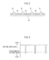
- FIG. 2 schematically shows a surface part of a catalyst carrier which is carried on a substrate of the exhaust purification catalyst 13 shown in FIG. 1 .
- a catalyst carrier 50 made of alumina on which precious metal catalysts 51 comprised of platinum Pt are carried.
- a basic layer 52 is formed which includes at least one element selected from potassium K, sodium Na, cesium Cs, or another such alkali metal, barium Ba, calcium Ca, or another such alkali earth metal, a lanthanide or another such rare earth and silver Ag, copper Cu, iron Fe, iridium Ir, or another metal able to donate electrons to NO x .
- rhodium Rh or palladium Pd may be further carried.
- the exhaust purification catalyst 13 is comprised of an NO x storage catalyst. If referring to the ratio of the air and fuel (hydrocarbons) which are supplied into the engine intake passage, combustion chamber 2, and exhaust passage upstream of the exhaust purification catalyst 13 as the "air-fuel ratio of exhaust gas", the exhaust purification catalyst 13 functions to store NO x when the air-fuel ratio of the exhaust gas is lean and to release the stored NO x when the air-fuel ratio of the exhaust gas is made rich. That is, when the air-fuel ratio of the exhaust gas is lean, the NO x which is contained in exhaust gas is oxidized on the platinum Pt51 and diffuses in the form of nitrate acid ions NO 3 - inside the basic layer 52 to become nitrates.
- the NO x in the exhaust gas is stored in the form of nitrates inside the basic layer 52.
- the concentration of oxygen in the exhaust gas falls, so the reaction proceeds in the opposite direction (NO 3 - ⁇ NO 2 ) and therefore the nitrates which are absorbed in the basic layer 52 successively become nitrate acid ions NO 3 - which are released in the form of NO 2 from the basic layer 52.
- the released NO 2 is reduced by the hydrocarbons HC and CO which are contained in the exhaust gas.
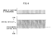
- FIG. 3 shows the case where a little before the NO x storage ability of the basic layer 52 becomes saturated, the air-fuel ratio of the combustion gas in the combustion chamber 2 is made rich so as to make the air-fuel ratio (A/F)in of the exhaust gas flowing into the exhaust purification catalyst 13 temporarily rich.
- the air-fuel ratio of the combustion gas in the combustion chamber 2 is made rich so as to make the air-fuel ratio (A/F)in of the exhaust gas flowing into the exhaust purification catalyst 13 temporarily rich.
- hydrocarbons are injected from the hydrocarbon feed valve 15 to make the air-fuel ratio (A/F)in of the exhaust gas flowing into the exhaust purification catalyst temporarily rich. Note that, in the example which is shown in FIG. 3 , the time interval of this rich control is 1 minute or more.
- the NO x which was stored in the basicity layer 52 when the air-fuel ratio (A/F)in of the exhaust gas was lean is released and reduced from the basic layer 52 all at once when the air-fuel ratio (A/F)in of the exhaust gas is made temporarily rich.
- the storage and release of NO x of the exhaust purification catalyst 13 in this way to remove NO x an extremely high NO x purification rate is obtained when the catalyst temperature TC is 250°C to 300°C, but the NO x purification rate falls when the catalyst temperature TC becomes a high temperature of 350°C or more.
- FIGS. 5A and 5B schematically show the surface parts of a catalyst carrier 50 of the exhaust purification catalyst 13.
- FIGS. 5A and 5B show the reaction which is believed to occur due to the air-fuel ratio (A/F)in of the exhaust gas which flows into the exhaust purification catalyst 13 being made rich within a predetermined range of period.
- FIG. 5A shows when the air-fuel ratio (A/F)in of the exhaust gas flowing into the exhaust purification catalyst 13 is lean
- FIG. 5B shows when hydrocarbons are fed from the hydrocarbon feed valve 15 and the air-fuel ratio (A/F)in of the exhaust gas flowing into the exhaust purification catalyst 13 is made rich.
- the air-fuel ratio of the exhaust gas flowing into the exhaust purification catalyst 13 is maintained lean except for one instant, so the exhaust gas flowing into the exhaust purification catalyst 13 usually becomes a state of oxygen excess.
- part of the NO which is contained in the exhaust gas deposits on the exhaust purification catalyst 13, and part of the NO which is contained in the exhaust gas, as shown in FIG. 5A , is oxidized on the platinum 51 and becomes NO 2 .
- this NO 2 is further oxidized and becomes NO 3 .
- part of the NO 2 becomes NO 2 - . Therefore, NO 2 - and NO 3 are formed on the platinum Pt51.
- the NO which deposits on the exhaust purification catalyst 13 and the NO 2 - and NO 3 which are formed on the platinum Pt51 are highly active. Therefore, below, these NO and NO 2 - and NO 3 will be referred to as "active NO x *".
- the active NO x * will react on the platinum 51 with the radical hydrocarbons HC whereby a reducing intermediate will be generated.
- This reducing intermediate is deposited on or adsorbed at the surface of the basic layer 52. Note that, at this time, the majority of the reducing intermediate which is held or adsorbed on the surface of the basic layer 52 is believed to be the isocyanate compound R-NCO and amine compound R-NH 2 .
- the NO x contained in the exhaust gas will react with the reducing intermediate R-NCO and R-NH 2 which is held or adsorbed on the surface of the basic layer 52 and be converted to N 2 , CO 2 , and H 2 O as shown in FIG. 5A .
- the NO x contained in the exhaust gas is removed by the reducible intermediate which is generated when hydrocarbons are injected from the hydrocarbon feed valve 15 and which is held or adsorbed on the surface of the basic layer 52. Therefore, to remove NO x well, it is necessary to generate a sufficient amount of reducing intermediate for removing the NO x and make the generated reducing intermediate be held or adsorbed on the basic layer 52.
- the injection period of hydrocarbons from the hydrocarbon feed valve 15, that is, the injection interval It becomes longer, the time period during which oxygen is in excess between when hydrocarbons are injected and when hydrocarbons are next injected becomes longer.
- the injection period of the hydrocarbons, that is, the injection interval It becomes longer than 5 seconds or so, the active NO x * will start to be absorbed in the basic layer 52 in the form of nitrates. Therefore, as shown in FIG. 6 , if the injection period of the hydrocarbons, that is, the injection interval It, becomes longer than 5 seconds or so, the NO x purification rate will fall.
- the injection period of the hydrocarbons that is, the injection interval It
- the injection period of the hydrocarbons is made from 0.3 second to 5 seconds.
- the NO x purification rate will fall if the catalyst temperature TC becomes a high temperature of 350°C or more.
- the NO x purification rate falls in this way if the catalyst temperature TC becomes 350°C or more because if the catalyst temperature TC becomes 350°C or more, NO x will become harder to store and the nitrates will break down under heat and be discharged from the exhaust purification catalyst 13 in the form of NO 2 . That is, so long as storing NO x in the form of nitrates, obtaining a high NO x purification rate is difficult when the catalyst temperature TC is high.
- the NO x purification method which is shown in FIGS. 4 and 5A and 5B , the amount of NO x which is stored in the form of nitrates is small and therefore even when the catalyst temperature TC is a high temperature of 400°C or more, a high NO x purification rate can be obtained.
- the NO x removal method which is shown in this FIGS. 4 and 5A and 5B will be referred to below as the "first NO x removal method”
- the NO x removal method which utilizes the storage and release of NO x which is shown in FIG. 3 will be referred to below as the "second NO x removal method”.
- FIG. 7 shows the changes in amount of injection of hydrocarbons from the hydrocarbon feed valve 15 and the air-fuel ratio (A/F)in of the exhaust gas flowing into the exhaust purification catalyst 13 when hydrocarbons are injected from the hydrocarbon feed valve 15 to raise an temperature of an exhaust treatment device such as the particulate filter 14 or the exhaust purification catalyst 13.
- an exhaust treatment device such as the particulate filter 14 or the exhaust purification catalyst 13.
- the amount of NO x (mg/s) flowing into the exhaust purification catalyst 13 per unit time increases, the amount of injection of hydrocarbons per unit time which becomes necessary for reducing the NO x flowing into the exhaust purification catalyst 13, that is, the injection density (mg/s), has to be increased.
- the NO x flowing into the exhaust purification catalyst 13 is reduced by the reducing intermediate which is held or adsorbed on the basic layer 52.
- the time during which the reducing intermediate is held or adsorbed on the basic layer 52 becomes shorter the higher the temperature TC of the exhaust purification catalyst 13.
- the time during which the reducing intermediate is held or adsorbed at the basic layer 52 becomes shorter in this way, to reduce well the NO x flowing into the exhaust purification catalyst 13, it becomes necessary to generate a large amount of reducing intermediate in a short time, and to this end, it is necessary to increase the injection density (mg/s) of the hydrocarbons. Therefore, when the temperature TC of the exhaust purification catalyst 13 becomes higher, it is necessary to increase the injection density (mg/s) of the hydrocarbons.
- the injection density (mg/s) of hydrocarbons per unit time which is required for reducing the NO x flowing into the exhaust purification catalyst 13, as shown in FIG. 8A , becomes a function of the amount of NO x (mg/s) flowing into the exhaust purification catalyst 13 per unit time and the temperature TC of the exhaust purification catalyst 13.
- the solid line DX shows the equivalent injection density line of hydrocarbons. Therefore, from FIG. 8A , it will be understood that the injection density DX (mg/s) of hydrocarbons increases along with an increase of the amount of NO x (mg/s) and increases along with a rise in the temperature TC of the exhaust purification catalyst 13.
- this injection density DX (mg/s) of hydrocarbons is stored as a function of the amount of NO x (mg/s) flowing into the exhaust purification catalyst 13 per unit time and the temperature TC of the exhaust purification catalyst 13 in the form of a map such as shown in FIG. 8B in advance in the ROM 32.
- the concentration of the hydrocarbons flowing into the exhaust purification catalyst 13 has to be raised. For this, it is necessary to increase the amount of injection of hydrocarbons per injection from the hydrocarbon feed valve 15. However, if increasing the amount of injection of hydrocarbons per injection from the hydrocarbon feed valve 15 to raise the concentration of the hydrocarbons which flow into the exhaust purification catalyst 13, hydrocarbons will slip through the exhaust purification catalyst 13. Therefore, the amount of injection (mg) of hydrocarbons per injection is made an amount giving the highest amount of generation of reducing intermediate without causing slip through of hydrocarbons.
- the amount of injection (mg) of hydrocarbons per injection becomes a function of the amount of injection Q (mg) of fuel which is injected into the combustion chamber 2 and the engine speed N.
- the solid line W shows the equevalent amounts of injection of hydrocarbons. Therefore, from FIG. 9A , it will be understood that the amount of injection W (mg) of hydrocarbons per injection increases as the amount of injection Q (mg) of fuel increases and increases as the engine speed N becomes higher.
- the optimum amount of injection W (mg) of hydrocarbons per injection is stored as a function of the amount of injection Q (mg) of fuel into the combustion chamber 2 and the engine speed N is the form of a map such as shown in FIG. 9B in advance in the ROM 32.
- the injection interval It of hydrocarbons is calculated by dividing the amount of injection W (mg) of hydrocarbons per injection shown in FIG. 9B by the injection density DX (mg/s) of hydrocarbons shown in FIG. 8B . In this case, if injecting hydrocarbons by the amount of injection (mg) per injection which is found from the map shown in FIG.
- the concentration of hydrocarbons flowing into the exhaust purification catalyst 13 becomes a concentration giving the highest amount of generation of reducing intermediate without causing slip through of hydrocarbons. Therefore, it is possible to keep down the amount of consumption of hydrocarbons while removing well the NO x contained in exhaust gas without causing slip through of hydrocarbons.
- the injection density (mg/s) of hydrocarbons per unit time becomes a function of the temperature difference (TG-TC) between the current temperature TC of the exhaust treatment device 13, 14 and the target temperature TG and the amount of exhaust gas (g/s).
- the solid line DY shows the equivalent injection density of hydrocarbons. Therefore, from FIG. 10A , it is learned that the injection density DY (mg/s) of hydrocarbons per unit time is made higher the larger the temperature difference (TG-TC) and is made higher the larger the amount of exhaust gas (g/s).
- the injection density DY (mg/s) of hydrocarbons per unit time when raising the temperature of the particulate filter 14 is stored as a function of the temperature difference (TG-TC) and the amount of exhaust gas (g/s) in the form of a map such as shown in FIG. 10B in advance in the ROM 32.
- the injection interval It of hydrocarbons is calculated by dividing the amount of injection W (mg) of hydrocarbons per injection shown in FIG. 9B by the injection density DY (mg/s) of hydrocarbons shown in FIG. 10B . In this case, if injecting hydrocarbons by the amount of injection (mg) per injection which is found from the map shown in FIG.
- the concentration of hydrocarbons flowing into the exhaust purification catalyst 13 becomes a concentration enabling the particulate filter 14 to be quickly raised to the target temperature without overshooting it and without causing slip through of hydrocarbons. Therefore, it is possible to suppress the consumption of hydrocarbons while making the particulate filter 14 quickly rise to the target temperature without overshooting it and without causing slip through of hydrocarbons.
- the injection density (mg/s) of hydrocarbons per unit time when raising the temperature of the exhaust purification catalyst 13 to release the SO x stored in the exhaust purification catalyst 13 from the exhaust purification catalyst 13 is also stored in the form of a map such as shown in FIG. 10B in advance in the ROM 32.
- the injection interval It of hydrocarbons is calculated by dividing the amount of injection W (mg) of hydrocarbons per injection shown in FIG. 9B by the injection density (mg/s) of hydrocarbons stored in advance in the ROM 32. In this case as well, if injecting hydrocarbons by the amount of injection (mg) per injection which is found from the map shown in FIG.
- the concentration of hydrocarbons flowing into the exhaust purification catalyst 13 becomes a concentration enabling the exhaust purification catalyst 13 to be quickly raised to the SO x release temperature without overshooting it and without causing slip through of hydrocarbons. Therefore, it is possible to suppress the consumption of hydrocarbons while making the exhaust purification catalyst 13 quickly rise to the SO x release temperature without overshooting it and without causing slip through of hydrocarbons.
- this injection interval It is calculated by dividing the amount of injection W (mg) of hydrocarbons per injection which is shown in FIG. 9B by the injection density DX (mg/s) of hydrocarbons which is shown in FIG. 8B .
- the concentration of the hydrocarbons which flow into the exhaust purification catalyst 13 becomes the concentration giving the highest amount of generation of reducible intermediate without causing slip through of hydrocarbons. Therefore, it becomes possible to suppress the amount of consumption of hydrocarbons while removing well the NO x which is contained in the exhaust gas without slip through of hydrocarbons.
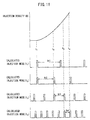
- FIG. 11 shows the case where the amount of NO x (mg/s) flowing into the exhaust purification catalyst 13 per unit time increases as time elapses from t 1 to t 4 .
- the injection density DX (mg/s) of hydrocarbons per unit time increase along with the elapse of time.
- FIG. 11 shows the calculated injection modes (t 1 ), (t 2 ), (t 3 ), and (t 4 ) at the times t 1 , t 2 , t 3 , and t 4 , that is, the amounts of injection W (mg) of hydrocarbons per injection calculated at the times t 1 , t 2 , t 3 , and t 4 and the injection intervals It1, It2, It3, and It4 calculated at the times t 1 , t 2 , t 3 , and t 4 .
- the amount of injection W (mg) of hydrocarbons per injection shown in FIG.
- the amount of injection W (mg) of hydrocarbons per injection shown in FIG. 9B at the time of the time t 2 and the injection interval It2 calculated by dividing this amount of injection W (mg) of hydrocarbons per injection by the injection density DX (mg/s) of hydrocarbons at the time t 2 shown in FIG. 11 are shown.
- the amount of injection W (mg) of hydrocarbons per injection shown in FIG. 9B at the time of the time t 3 and the injection interval It3 calculated by dividing this amount of injection W (mg) of hydrocarbons per injection by the injection density DX (mg/s) of hydrocarbons at the time t 3 shown in FIG. 11 are shown.
- the injection intervals It1, It2, It3, and It4 at the calculated injection modes (t 1 ), (t 2 ), (t 3 ), and (t 4 ) become injection intervals giving the highest amounts of generation of reducing intermediate at the times t 1 , t 2 , t 3 , and t 4 without causing slip through of hydrocarbons. Therefore, at the times t 1 , t 2 , t 3 , and t 4 , if injecting hydrocarbons by the calculated amounts of injection (mg) per injection at the injection intervals It1, It2, It3, and It4, the concentration of hydrocarbons flowing into the exhaust purification catalyst 13 becomes a concentration giving the highest amount of generation of reducing intermediate without causing slip through of hydrocarbons.
- the injection intervals It1, It2, It3, and It4 become the best injection intervals at the times t 1 , t 2 , t 3 , and t 4 .
- the result becomes the best injection mode where it is possible to suppress the amount of consumption of hydrocarbons while removing the NO x contained in the exhaust gas well without causing slip through of hydrocarbons.
- the result becomes the best injection mode where it is possible to remove the NO x well
- the time t 4 if the injection interval between the previous injection at the time t 3 and the current injection at the time t 4 becomes the best injection interval It4 at the time t 4 , at the time t 4 , the result becomes the best injection mode where it is possible to remove the NO x well.
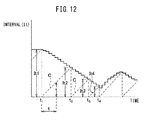
- the ordinate of FIG. 12 shows the injection interval It which is calculated from the injection density DX (mg/s) of hydrocarbons and the amount of injection W (mg) of hydrocarbons per injection, while the abscissa of FIG. 12 shows the time. Note that, on the abscissa of FIG. 12 , the times t 1 , t 2 , t 3 , and t 4 correspond to the times t 1 , t 2 , t 3 , and t 4 in FIG. 11 . In the embodiment which is shown in FIG. 12 , the calculation period of the injection interval It is a short period of 4 msec to 20 msec or so. Therefore, the injection interval It is continuously calculated by this short period.
- the injection period of hydrocarbons that is, the injection interval It
- the shortest injection interval It in this case is 0.3 second, that is, 300 msec, therefore it is learned that the calculation period of the injection interval It is smaller than the range of injection period of hydrocarbons (0.3 second to 5 seconds).
- the broken line which extends at a slant in FIG. 12 shows the value of the time counter C, that is, the elapsed time t. This time counter C is reset when injection is performed, so the elapsed time "t" shows the elapsed time from when injection was performed.
- the time counter C is reset at the times t 1 , t 2 , t 3 , and t 4 . Therefore, the elapsed time "t" shows the elapsed time from the times t 1 , t 2 , t 3 , and t 4 .
- injection control according to the present invention which is shown in FIG. 11 and FIG. 12 when using a urea aqueous solution as the reducing agent and controlling the amount of feed of urea aqueous solution in accordance with the amount of NO x .
- the control system comprises a calculating part which calculates a suitable injection interval It of the reducing agent corresponding to an operating state of the engine at the time of calculation with a predetermined fixed calculation period and which updates an injection interval by using the calculated injection interval It as an updated new injection interval It, and an injection executing part which executes a next injection of the reducing agent from the reducing agent feed valve 15 when an elapsed time from when a previous injection was performed becomes the new injection interval It or more which was updated to by the calculating part after the previous injection was performed.
- a control method of an internal combustion engine in which a reducing agent is intermittently injected into an engine exhaust passage from a reducing agent feed valve 15 within a predetermined range of period to remove NO x contained in an exhaust gas or to raise a temperature of an exhaust treatment device 13, 14, the control method comprises: calculating a suitable injection interval It of the reducing agent corresponding to an operating state of the engine at the time of calculation with a predetermined fixed calculation period and updating an injection interval by using the calculated injection interval It as an updated new injection interval It, and executing a next injection of the reducing agent from the reducing agent feed valve 15 when an elapsed time from when a previous injection was performed becomes the new injection interval It or more which was updated to by the calculating part after the previous injection was performed.
- the electronic control unit 30 forms the calculating part and the injection executing part.
- the predetermined fixed calculation period of the injection interval It is shorter than the range of the injection period of the reducing agent from the reducing agent feed valve 15.
- the injection density DX, DY of the reducing agent and the amount of injection W per injection are calculated at the predetermined fixed calculation period, and the optimum injection interval It is found by dividing the amount of injection W per injection by the injection density DX, DY.
- FIG. 13 shows an exhaust purification control routine for injection control according to the present invention. This routine is executed repeatedly at time intervals of 0.3 second to 5 seconds.
- step 80 it is judged if a temperature elevation request which shows that an exhaust treatment device 13, 14 such as the exhaust purification catalyst 13 or particulate filter 14 should be raised in temperature is issued.
- the routine proceeds to step 81 where it is judged if the operating state is one where the first NO x removal method should be used to remove NO x .
- the routine proceeds to step 82 where the injection density DX (mg/s) of hydrocarbons is calculated from the map shown in FIG. 8B .
- step 83 the optimum amount of injection W (mg) of hydrocarbons per injection is calculated from the map shown in FIG. 9B .
- the injection interval It of hydrocarbons is calculated by dividing the amount of injection W (mg) of hydrocarbons per injection which was calculated at step 83 by the injection density DX (mg/s) of hydrocarbons which was calculated at step 82.
- the elapsed time "t" from when the previous injection was performed becomes the injection interval It which was calculated at step 84 or more.
- This elapsed time is calculated by the elapsed time calculation routine shown in FIG. 14 .
- This elapsed time calculation routine is repeatedly executed every fixed time ⁇ t.
- step 85 when it is judged at step 85 that the elapsed time "t" from when the previous injection was performed becomes the injection interval It which was calculated at step 84 or more, the routine proceeds to step 86 where the injection time from the hydrocarbon feed valve 15 which is required for injecting the amount of injection W which was calculated at step 83 is calculated.
- step 87 an injection command which shows that the hydrocarbon feed valve 15 should inject hydrocarbons is issued. If the injection command is issued, hydrocarbons are injected from the hydrocarbon feed valve 15 over the injection time which is calculated at step 86.
- step 88 the elapsed time "t” is cleared. If the elapsed time "t” is cleared, the elapsed time calculation routine which is shown in FIG. 14 is used to again start the calculation of the elapsed time "t" from zero.
- step 81 when it is judged at step 81 that the operating state is not one where the first NO x removal method should be used to remove NO x , the routine proceeds to step 89 where the second NO x removal method is used to remove NO x . That is, at step 89, the amount of NO x stored in the exhaust purification catalyst 13 is calculated. Specifically speaking, if the operating state of the engine is determined, the amount of NO x discharged from the engine is determined, so the amount of NO x which is stored at the exhaust purification catalyst 13 is calculated by cumulatively adding the amount of NO x discharged from the engine. Next, at step 90, it is judged if the amount of NO x which is stored in the exhaust purification catalyst 13 exceeds a predetermined allowable value MAX.
- the routine proceeds to step 91 where the air-fuel ratio of the exhaust gas flowing into the exhaust purification catalyst 13 is made temporarily rich to release NO x from the exhaust purification catalyst 13.
- step 80 when it is judged at step 80 that the temperature elevation request which shows that the temperature of an exhaust treatment device 13, 14 such as the exhaust purification catalyst 13 or particulate filter 14 should be raised is issued, the routine proceeds to step 92 where temperature elevation control is performed. That is, when the temperature elevation request which shows that the particulate filter 14 should be raised in temperature is issued, the injection density DY (mg/s) of hydrocarbons per unit time is calculated from the map shown in FIG. 10B , next, at step 93, the optimum amount of injection W (mg) of hydrocarbons per injection is calculated from the map shown in FIG. 9B .
- the injection interval It of hydrocarbons is calculated by dividing the amount of injection W (mg) of hydrocarbons per injection which was calculated at step 93 by the injection density DY (mg/s) of hydrocarbons which was calculated at step 92.
- step 95 it is judged if the elapsed time "t" from when the previous injection was performed becomes the injection interval It which was calculated at step 94 or more.
- the routine proceeds to step 96 where the injection time from the hydrocarbon feed valve 15 which is required for injecting the amount of injection W which was calculated at step 93 is calculated.
- step 97 an injection command which shows that the hydrocarbon feed valve 15 should inject hydrocarbons is made to be issued. If the injection command is made to be issued, hydrocarbons are injected from the hydrocarbon feed valve 15 over the injection time which was calculated at step 96.
- step 98 the elapsed time "t" is cleared.
- the injection density DY (mg/s) of hydrocarbons per unit time is calculated from a separate map similar to the map shown in FIG. 10B
- the optimal amount of injection W (mg) of hydrocarbons per injection is calculated from the map shown in FIG. 9B .
- the injection interval It of hydrocarbons is calculated by dividing the amount of injection W (mg) of hydrocarbons per injection which was calculated at step 93 by the injection density DY (mg/s) of hydrocarbons which was calculated at step 92.
- processing similar to the time of the above-mentioned temperature elevation control of the exhaust treatment device 13, 14 is performed.
Landscapes
- Engineering & Computer Science (AREA)
- Chemical & Material Sciences (AREA)
- Combustion & Propulsion (AREA)
- Mechanical Engineering (AREA)
- General Engineering & Computer Science (AREA)
- Chemical Kinetics & Catalysis (AREA)
- Exhaust Gas After Treatment (AREA)
- Exhaust Gas Treatment By Means Of Catalyst (AREA)
Applications Claiming Priority (1)
| Application Number | Priority Date | Filing Date | Title |
|---|---|---|---|
| JP2014166727A JP6036764B2 (ja) | 2014-08-19 | 2014-08-19 | 内燃機関の制御装置および制御方法 |
Publications (3)
| Publication Number | Publication Date |
|---|---|
| EP2987977A1 true EP2987977A1 (de) | 2016-02-24 |
| EP2987977A8 EP2987977A8 (de) | 2016-06-01 |
| EP2987977B1 EP2987977B1 (de) | 2016-10-12 |
Family
ID=53539507
Family Applications (1)
| Application Number | Title | Priority Date | Filing Date |
|---|---|---|---|
| EP15174858.9A Not-in-force EP2987977B1 (de) | 2014-08-19 | 2015-07-01 | Steuerungssystem und steuerungsverfahren für einen verbrennungsmotor |
Country Status (2)
| Country | Link |
|---|---|
| EP (1) | EP2987977B1 (de) |
| JP (1) | JP6036764B2 (de) |
Cited By (2)
| Publication number | Priority date | Publication date | Assignee | Title |
|---|---|---|---|---|
| CN113356973A (zh) * | 2021-05-28 | 2021-09-07 | 广西玉柴机器股份有限公司 | 一种变频脉冲式喷射的方法及相关装置 |
| DE112019001205B4 (de) | 2018-03-08 | 2022-08-18 | Cummins Emission Solutions Inc. | Systeme und Verfahren zum Steuern von Kolbenpumpen |
Citations (6)
| Publication number | Priority date | Publication date | Assignee | Title |
|---|---|---|---|---|
| EP0733786A2 (de) * | 1995-03-24 | 1996-09-25 | Toyota Jidosha Kabushiki Kaisha | Abgasreinigungsvorrichtung für Brennkraftmaschine |
| EP1176289A2 (de) * | 2000-07-24 | 2002-01-30 | Toyota Jidosha Kabushiki Kaisha | Abgasemissions-Steuerungssystem für Verbrennungsmotoren |
| US20050076635A1 (en) * | 2003-10-09 | 2005-04-14 | Toyota Jidosha Kabushiki Kaisha | Air fuel ratio control apparatus for an internal combustion engine |
| WO2011114501A1 (ja) | 2010-03-15 | 2011-09-22 | トヨタ自動車株式会社 | 内燃機関の排気浄化装置 |
| EP2511493A1 (de) * | 2011-02-18 | 2012-10-17 | Toyota Jidosha Kabushiki Kaisha | Abgasreinigungssystem für einen verbrennungsmotor |
| WO2013121520A1 (ja) * | 2012-02-14 | 2013-08-22 | トヨタ自動車株式会社 | 内燃機関の排気浄化装置 |
Family Cites Families (8)
| Publication number | Priority date | Publication date | Assignee | Title |
|---|---|---|---|---|
| FI20010973A (fi) * | 2001-05-09 | 2002-11-10 | Valtion Teknillinen | Katalysaattori ja menetelmä typpioksidien katalyyttiseksi pelkistämiseksi |
| JP2008163856A (ja) * | 2006-12-28 | 2008-07-17 | Toyota Motor Corp | 内燃機関の排気浄化装置 |
| JP2009209766A (ja) * | 2008-03-04 | 2009-09-17 | Toyota Motor Corp | 内燃機関の排気浄化装置 |
| JP5196026B2 (ja) * | 2010-03-15 | 2013-05-15 | トヨタ自動車株式会社 | 内燃機関の排気浄化装置 |
| ES2534759T3 (es) * | 2010-03-15 | 2015-04-28 | Toyota Jidosha Kabushiki Kaisha | Sistema de purificación de gases de escape de motor de combustión interna |
| EP2447488B1 (de) * | 2010-08-30 | 2015-11-25 | Toyota Jidosha Kabushiki Kaisha | Abgasreinigungsvorrichtung für einen verbrennungsmotor |
| CN103221648B (zh) * | 2010-12-06 | 2016-08-24 | 丰田自动车株式会社 | 内燃机的排气净化装置 |
| CN103097678B (zh) * | 2011-08-25 | 2015-04-08 | 丰田自动车株式会社 | 内燃机的排气净化装置 |
-
2014
- 2014-08-19 JP JP2014166727A patent/JP6036764B2/ja not_active Expired - Fee Related
-
2015
- 2015-07-01 EP EP15174858.9A patent/EP2987977B1/de not_active Not-in-force
Patent Citations (6)
| Publication number | Priority date | Publication date | Assignee | Title |
|---|---|---|---|---|
| EP0733786A2 (de) * | 1995-03-24 | 1996-09-25 | Toyota Jidosha Kabushiki Kaisha | Abgasreinigungsvorrichtung für Brennkraftmaschine |
| EP1176289A2 (de) * | 2000-07-24 | 2002-01-30 | Toyota Jidosha Kabushiki Kaisha | Abgasemissions-Steuerungssystem für Verbrennungsmotoren |
| US20050076635A1 (en) * | 2003-10-09 | 2005-04-14 | Toyota Jidosha Kabushiki Kaisha | Air fuel ratio control apparatus for an internal combustion engine |
| WO2011114501A1 (ja) | 2010-03-15 | 2011-09-22 | トヨタ自動車株式会社 | 内燃機関の排気浄化装置 |
| EP2511493A1 (de) * | 2011-02-18 | 2012-10-17 | Toyota Jidosha Kabushiki Kaisha | Abgasreinigungssystem für einen verbrennungsmotor |
| WO2013121520A1 (ja) * | 2012-02-14 | 2013-08-22 | トヨタ自動車株式会社 | 内燃機関の排気浄化装置 |
Cited By (3)
| Publication number | Priority date | Publication date | Assignee | Title |
|---|---|---|---|---|
| DE112019001205B4 (de) | 2018-03-08 | 2022-08-18 | Cummins Emission Solutions Inc. | Systeme und Verfahren zum Steuern von Kolbenpumpen |
| CN113356973A (zh) * | 2021-05-28 | 2021-09-07 | 广西玉柴机器股份有限公司 | 一种变频脉冲式喷射的方法及相关装置 |
| CN113356973B (zh) * | 2021-05-28 | 2022-04-01 | 广西玉柴机器股份有限公司 | 一种变频脉冲式喷射的方法及相关装置 |
Also Published As
| Publication number | Publication date |
|---|---|
| JP6036764B2 (ja) | 2016-11-30 |
| EP2987977A8 (de) | 2016-06-01 |
| EP2987977B1 (de) | 2016-10-12 |
| JP2016044551A (ja) | 2016-04-04 |
Similar Documents
| Publication | Publication Date | Title |
|---|---|---|
| US9631535B2 (en) | Exhaust purification system of internal combustion engine | |
| EP2623738A1 (de) | Abgasreinigungsvorrichtung für einen verbrennungsmotor | |
| EP2955348B1 (de) | Abgasreinigungssystem eines verbrennungsmotors | |
| EP2960455B1 (de) | Abgasreinigungsvorrichtung für einen verbrennungsmotor | |
| EP2985431B1 (de) | Abgasreinigungsvorrichtung für einen verbrennungsmotor | |
| EP2987977B1 (de) | Steuerungssystem und steuerungsverfahren für einen verbrennungsmotor | |
| EP3091205B1 (de) | Abgasreinigungssystem für verbrennungsmotor | |
| EP3030763B1 (de) | Abgasreinigungsvorrichtung für einen verbrennungsmotor | |
| US9567889B2 (en) | Exhaust purification system for internal combustion engine | |
| EP3085935B1 (de) | Abgasreinigungsvorrichtung für einen verbrennungsmotor | |
| EP2846028A1 (de) | Steuerungsvorrichtung eines Verbrennungsmotors | |
| US9784155B2 (en) | Exhaust purification system for internal combustion engine | |
| EP2873818B1 (de) | Abgasreinigungssystem eines verbrennungsmotors | |
| US9926826B2 (en) | Internal combustion engine | |
| EP3036412B1 (de) | Abgasreinigungsvorrichtung für einen verbrennungsmotor | |
| EP2873820B1 (de) | Abgasreinigungssystem für einen Verbrennungsmotor | |
| EP2982851A2 (de) | Steuerungssystem eines verbrennungsmotors | |
| EP2835510A1 (de) | Abgasreinigungssystem für einen Verbrennungsmotor | |
| EP2835509B1 (de) | Abgasreinigungssystem für einen Verbrennungsmotor |
Legal Events
| Date | Code | Title | Description |
|---|---|---|---|
| PUAI | Public reference made under article 153(3) epc to a published international application that has entered the european phase |
Free format text: ORIGINAL CODE: 0009012 |
|
| 17P | Request for examination filed |
Effective date: 20150701 |
|
| AK | Designated contracting states |
Kind code of ref document: A1 Designated state(s): AL AT BE BG CH CY CZ DE DK EE ES FI FR GB GR HR HU IE IS IT LI LT LU LV MC MK MT NL NO PL PT RO RS SE SI SK SM TR |
|
| AX | Request for extension of the european patent |
Extension state: BA ME |
|
| RAP1 | Party data changed (applicant data changed or rights of an application transferred) |
Owner name: TOYOTA JIDOSHA KABUSHIKI KAISHA |
|
| RAP1 | Party data changed (applicant data changed or rights of an application transferred) |
Owner name: TOYOTA JIDOSHA KABUSHIKI KAISHA |
|
| RIN1 | Information on inventor provided before grant (corrected) |
Inventor name: BISAIJI, YUKI |
|
| GRAP | Despatch of communication of intention to grant a patent |
Free format text: ORIGINAL CODE: EPIDOSNIGR1 |
|
| RIC1 | Information provided on ipc code assigned before grant |
Ipc: F01N 9/00 20060101ALI20160504BHEP Ipc: F01N 3/025 20060101ALI20160504BHEP Ipc: F01N 3/08 20060101AFI20160504BHEP |
|
| INTG | Intention to grant announced |
Effective date: 20160603 |
|
| GRAS | Grant fee paid |
Free format text: ORIGINAL CODE: EPIDOSNIGR3 |
|
| GRAA | (expected) grant |
Free format text: ORIGINAL CODE: 0009210 |
|
| AK | Designated contracting states |
Kind code of ref document: B1 Designated state(s): AL AT BE BG CH CY CZ DE DK EE ES FI FR GB GR HR HU IE IS IT LI LT LU LV MC MK MT NL NO PL PT RO RS SE SI SK SM TR |
|
| REG | Reference to a national code |
Ref country code: GB Ref legal event code: FG4D |
|
| REG | Reference to a national code |
Ref country code: CH Ref legal event code: EP |
|
| REG | Reference to a national code |
Ref country code: AT Ref legal event code: REF Ref document number: 836725 Country of ref document: AT Kind code of ref document: T Effective date: 20161015 |
|
| REG | Reference to a national code |
Ref country code: IE Ref legal event code: FG4D |
|
| REG | Reference to a national code |
Ref country code: DE Ref legal event code: R096 Ref document number: 602015000466 Country of ref document: DE |
|
| REG | Reference to a national code |
Ref country code: LT Ref legal event code: MG4D |
|
| REG | Reference to a national code |
Ref country code: NL Ref legal event code: MP Effective date: 20161012 |
|
| PG25 | Lapsed in a contracting state [announced via postgrant information from national office to epo] |
Ref country code: LV Free format text: LAPSE BECAUSE OF FAILURE TO SUBMIT A TRANSLATION OF THE DESCRIPTION OR TO PAY THE FEE WITHIN THE PRESCRIBED TIME-LIMIT Effective date: 20161012 |
|
| REG | Reference to a national code |
Ref country code: AT Ref legal event code: MK05 Ref document number: 836725 Country of ref document: AT Kind code of ref document: T Effective date: 20161012 |
|
| REG | Reference to a national code |
Ref country code: DE Ref legal event code: R084 Ref document number: 602015000466 Country of ref document: DE |
|
| PG25 | Lapsed in a contracting state [announced via postgrant information from national office to epo] |
Ref country code: SE Free format text: LAPSE BECAUSE OF FAILURE TO SUBMIT A TRANSLATION OF THE DESCRIPTION OR TO PAY THE FEE WITHIN THE PRESCRIBED TIME-LIMIT Effective date: 20161012 Ref country code: LT Free format text: LAPSE BECAUSE OF FAILURE TO SUBMIT A TRANSLATION OF THE DESCRIPTION OR TO PAY THE FEE WITHIN THE PRESCRIBED TIME-LIMIT Effective date: 20161012 Ref country code: GR Free format text: LAPSE BECAUSE OF FAILURE TO SUBMIT A TRANSLATION OF THE DESCRIPTION OR TO PAY THE FEE WITHIN THE PRESCRIBED TIME-LIMIT Effective date: 20170113 Ref country code: NO Free format text: LAPSE BECAUSE OF FAILURE TO SUBMIT A TRANSLATION OF THE DESCRIPTION OR TO PAY THE FEE WITHIN THE PRESCRIBED TIME-LIMIT Effective date: 20170112 |
|
| REG | Reference to a national code |
Ref country code: GB Ref legal event code: 746 Effective date: 20170421 |
|
| PG25 | Lapsed in a contracting state [announced via postgrant information from national office to epo] |
Ref country code: PL Free format text: LAPSE BECAUSE OF FAILURE TO SUBMIT A TRANSLATION OF THE DESCRIPTION OR TO PAY THE FEE WITHIN THE PRESCRIBED TIME-LIMIT Effective date: 20161012 Ref country code: IS Free format text: LAPSE BECAUSE OF FAILURE TO SUBMIT A TRANSLATION OF THE DESCRIPTION OR TO PAY THE FEE WITHIN THE PRESCRIBED TIME-LIMIT Effective date: 20170212 Ref country code: AT Free format text: LAPSE BECAUSE OF FAILURE TO SUBMIT A TRANSLATION OF THE DESCRIPTION OR TO PAY THE FEE WITHIN THE PRESCRIBED TIME-LIMIT Effective date: 20161012 Ref country code: RS Free format text: LAPSE BECAUSE OF FAILURE TO SUBMIT A TRANSLATION OF THE DESCRIPTION OR TO PAY THE FEE WITHIN THE PRESCRIBED TIME-LIMIT Effective date: 20161012 Ref country code: ES Free format text: LAPSE BECAUSE OF FAILURE TO SUBMIT A TRANSLATION OF THE DESCRIPTION OR TO PAY THE FEE WITHIN THE PRESCRIBED TIME-LIMIT Effective date: 20161012 Ref country code: BE Free format text: LAPSE BECAUSE OF FAILURE TO SUBMIT A TRANSLATION OF THE DESCRIPTION OR TO PAY THE FEE WITHIN THE PRESCRIBED TIME-LIMIT Effective date: 20161012 Ref country code: FI Free format text: LAPSE BECAUSE OF FAILURE TO SUBMIT A TRANSLATION OF THE DESCRIPTION OR TO PAY THE FEE WITHIN THE PRESCRIBED TIME-LIMIT Effective date: 20161012 Ref country code: NL Free format text: LAPSE BECAUSE OF FAILURE TO SUBMIT A TRANSLATION OF THE DESCRIPTION OR TO PAY THE FEE WITHIN THE PRESCRIBED TIME-LIMIT Effective date: 20161012 Ref country code: HR Free format text: LAPSE BECAUSE OF FAILURE TO SUBMIT A TRANSLATION OF THE DESCRIPTION OR TO PAY THE FEE WITHIN THE PRESCRIBED TIME-LIMIT Effective date: 20161012 Ref country code: PT Free format text: LAPSE BECAUSE OF FAILURE TO SUBMIT A TRANSLATION OF THE DESCRIPTION OR TO PAY THE FEE WITHIN THE PRESCRIBED TIME-LIMIT Effective date: 20170213 |
|
| REG | Reference to a national code |
Ref country code: FR Ref legal event code: PLFP Year of fee payment: 3 |
|
| REG | Reference to a national code |
Ref country code: DE Ref legal event code: R097 Ref document number: 602015000466 Country of ref document: DE |
|
| PG25 | Lapsed in a contracting state [announced via postgrant information from national office to epo] |
Ref country code: CZ Free format text: LAPSE BECAUSE OF FAILURE TO SUBMIT A TRANSLATION OF THE DESCRIPTION OR TO PAY THE FEE WITHIN THE PRESCRIBED TIME-LIMIT Effective date: 20161012 Ref country code: DK Free format text: LAPSE BECAUSE OF FAILURE TO SUBMIT A TRANSLATION OF THE DESCRIPTION OR TO PAY THE FEE WITHIN THE PRESCRIBED TIME-LIMIT Effective date: 20161012 Ref country code: EE Free format text: LAPSE BECAUSE OF FAILURE TO SUBMIT A TRANSLATION OF THE DESCRIPTION OR TO PAY THE FEE WITHIN THE PRESCRIBED TIME-LIMIT Effective date: 20161012 Ref country code: RO Free format text: LAPSE BECAUSE OF FAILURE TO SUBMIT A TRANSLATION OF THE DESCRIPTION OR TO PAY THE FEE WITHIN THE PRESCRIBED TIME-LIMIT Effective date: 20161012 Ref country code: SK Free format text: LAPSE BECAUSE OF FAILURE TO SUBMIT A TRANSLATION OF THE DESCRIPTION OR TO PAY THE FEE WITHIN THE PRESCRIBED TIME-LIMIT Effective date: 20161012 |
|
| PLBE | No opposition filed within time limit |
Free format text: ORIGINAL CODE: 0009261 |
|
| STAA | Information on the status of an ep patent application or granted ep patent |
Free format text: STATUS: NO OPPOSITION FILED WITHIN TIME LIMIT |
|
| PG25 | Lapsed in a contracting state [announced via postgrant information from national office to epo] |
Ref country code: BG Free format text: LAPSE BECAUSE OF FAILURE TO SUBMIT A TRANSLATION OF THE DESCRIPTION OR TO PAY THE FEE WITHIN THE PRESCRIBED TIME-LIMIT Effective date: 20170112 Ref country code: SM Free format text: LAPSE BECAUSE OF FAILURE TO SUBMIT A TRANSLATION OF THE DESCRIPTION OR TO PAY THE FEE WITHIN THE PRESCRIBED TIME-LIMIT Effective date: 20161012 |
|
| 26N | No opposition filed |
Effective date: 20170713 |
|
| PG25 | Lapsed in a contracting state [announced via postgrant information from national office to epo] |
Ref country code: SI Free format text: LAPSE BECAUSE OF FAILURE TO SUBMIT A TRANSLATION OF THE DESCRIPTION OR TO PAY THE FEE WITHIN THE PRESCRIBED TIME-LIMIT Effective date: 20161012 |
|
| REG | Reference to a national code |
Ref country code: IE Ref legal event code: MM4A |
|
| PG25 | Lapsed in a contracting state [announced via postgrant information from national office to epo] |
Ref country code: IE Free format text: LAPSE BECAUSE OF NON-PAYMENT OF DUE FEES Effective date: 20170701 |
|
| REG | Reference to a national code |
Ref country code: FR Ref legal event code: PLFP Year of fee payment: 4 |
|
| PG25 | Lapsed in a contracting state [announced via postgrant information from national office to epo] |
Ref country code: LU Free format text: LAPSE BECAUSE OF NON-PAYMENT OF DUE FEES Effective date: 20170701 |
|
| PG25 | Lapsed in a contracting state [announced via postgrant information from national office to epo] |
Ref country code: MT Free format text: LAPSE BECAUSE OF NON-PAYMENT OF DUE FEES Effective date: 20170701 |
|
| REG | Reference to a national code |
Ref country code: CH Ref legal event code: PL |
|
| PG25 | Lapsed in a contracting state [announced via postgrant information from national office to epo] |
Ref country code: CH Free format text: LAPSE BECAUSE OF NON-PAYMENT OF DUE FEES Effective date: 20180731 Ref country code: LI Free format text: LAPSE BECAUSE OF NON-PAYMENT OF DUE FEES Effective date: 20180731 |
|
| PG25 | Lapsed in a contracting state [announced via postgrant information from national office to epo] |
Ref country code: MC Free format text: LAPSE BECAUSE OF FAILURE TO SUBMIT A TRANSLATION OF THE DESCRIPTION OR TO PAY THE FEE WITHIN THE PRESCRIBED TIME-LIMIT Effective date: 20161012 Ref country code: HU Free format text: LAPSE BECAUSE OF FAILURE TO SUBMIT A TRANSLATION OF THE DESCRIPTION OR TO PAY THE FEE WITHIN THE PRESCRIBED TIME-LIMIT; INVALID AB INITIO Effective date: 20150701 |
|
| PGFP | Annual fee paid to national office [announced via postgrant information from national office to epo] |
Ref country code: FR Payment date: 20190619 Year of fee payment: 5 |
|
| PG25 | Lapsed in a contracting state [announced via postgrant information from national office to epo] |
Ref country code: CY Free format text: LAPSE BECAUSE OF FAILURE TO SUBMIT A TRANSLATION OF THE DESCRIPTION OR TO PAY THE FEE WITHIN THE PRESCRIBED TIME-LIMIT Effective date: 20161012 |
|
| PGFP | Annual fee paid to national office [announced via postgrant information from national office to epo] |
Ref country code: DE Payment date: 20190618 Year of fee payment: 5 Ref country code: GB Payment date: 20190626 Year of fee payment: 5 Ref country code: IT Payment date: 20190719 Year of fee payment: 5 |
|
| PG25 | Lapsed in a contracting state [announced via postgrant information from national office to epo] |
Ref country code: MK Free format text: LAPSE BECAUSE OF FAILURE TO SUBMIT A TRANSLATION OF THE DESCRIPTION OR TO PAY THE FEE WITHIN THE PRESCRIBED TIME-LIMIT Effective date: 20161012 |
|
| PG25 | Lapsed in a contracting state [announced via postgrant information from national office to epo] |
Ref country code: TR Free format text: LAPSE BECAUSE OF FAILURE TO SUBMIT A TRANSLATION OF THE DESCRIPTION OR TO PAY THE FEE WITHIN THE PRESCRIBED TIME-LIMIT Effective date: 20161012 |
|
| PG25 | Lapsed in a contracting state [announced via postgrant information from national office to epo] |
Ref country code: AL Free format text: LAPSE BECAUSE OF FAILURE TO SUBMIT A TRANSLATION OF THE DESCRIPTION OR TO PAY THE FEE WITHIN THE PRESCRIBED TIME-LIMIT Effective date: 20161012 |
|
| REG | Reference to a national code |
Ref country code: DE Ref legal event code: R119 Ref document number: 602015000466 Country of ref document: DE |
|
| GBPC | Gb: european patent ceased through non-payment of renewal fee |
Effective date: 20200701 |
|
| PG25 | Lapsed in a contracting state [announced via postgrant information from national office to epo] |
Ref country code: FR Free format text: LAPSE BECAUSE OF NON-PAYMENT OF DUE FEES Effective date: 20200731 Ref country code: GB Free format text: LAPSE BECAUSE OF NON-PAYMENT OF DUE FEES Effective date: 20200701 |
|
| PG25 | Lapsed in a contracting state [announced via postgrant information from national office to epo] |
Ref country code: DE Free format text: LAPSE BECAUSE OF NON-PAYMENT OF DUE FEES Effective date: 20210202 |
|
| PG25 | Lapsed in a contracting state [announced via postgrant information from national office to epo] |
Ref country code: IT Free format text: LAPSE BECAUSE OF NON-PAYMENT OF DUE FEES Effective date: 20200701 |