EP2960455B1 - Abgasreinigungsvorrichtung für einen verbrennungsmotor - Google Patents
Abgasreinigungsvorrichtung für einen verbrennungsmotor Download PDFInfo
- Publication number
- EP2960455B1 EP2960455B1 EP13876028.5A EP13876028A EP2960455B1 EP 2960455 B1 EP2960455 B1 EP 2960455B1 EP 13876028 A EP13876028 A EP 13876028A EP 2960455 B1 EP2960455 B1 EP 2960455B1
- Authority
- EP
- European Patent Office
- Prior art keywords
- purification catalyst
- exhaust purification
- exhaust
- rich
- exhaust gas
- Prior art date
- Legal status (The legal status is an assumption and is not a legal conclusion. Google has not performed a legal analysis and makes no representation as to the accuracy of the status listed.)
- Active
Links
Images


Classifications
-
- F—MECHANICAL ENGINEERING; LIGHTING; HEATING; WEAPONS; BLASTING
- F01—MACHINES OR ENGINES IN GENERAL; ENGINE PLANTS IN GENERAL; STEAM ENGINES
- F01N—GAS-FLOW SILENCERS OR EXHAUST APPARATUS FOR MACHINES OR ENGINES IN GENERAL; GAS-FLOW SILENCERS OR EXHAUST APPARATUS FOR INTERNAL COMBUSTION ENGINES
- F01N3/00—Exhaust or silencing apparatus having means for purifying, rendering innocuous, or otherwise treating exhaust
- F01N3/08—Exhaust or silencing apparatus having means for purifying, rendering innocuous, or otherwise treating exhaust for rendering innocuous
- F01N3/10—Exhaust or silencing apparatus having means for purifying, rendering innocuous, or otherwise treating exhaust for rendering innocuous by thermal or catalytic conversion of noxious components of exhaust
- F01N3/18—Exhaust or silencing apparatus having means for purifying, rendering innocuous, or otherwise treating exhaust for rendering innocuous by thermal or catalytic conversion of noxious components of exhaust characterised by methods of operation; Control
- F01N3/20—Exhaust or silencing apparatus having means for purifying, rendering innocuous, or otherwise treating exhaust for rendering innocuous by thermal or catalytic conversion of noxious components of exhaust characterised by methods of operation; Control specially adapted for catalytic conversion ; Methods of operation or control of catalytic converters
- F01N3/206—Adding periodically or continuously substances to exhaust gases for promoting purification, e.g. catalytic material in liquid form, NOx reducing agents
-
- F—MECHANICAL ENGINEERING; LIGHTING; HEATING; WEAPONS; BLASTING
- F01—MACHINES OR ENGINES IN GENERAL; ENGINE PLANTS IN GENERAL; STEAM ENGINES
- F01N—GAS-FLOW SILENCERS OR EXHAUST APPARATUS FOR MACHINES OR ENGINES IN GENERAL; GAS-FLOW SILENCERS OR EXHAUST APPARATUS FOR INTERNAL COMBUSTION ENGINES
- F01N3/00—Exhaust or silencing apparatus having means for purifying, rendering innocuous, or otherwise treating exhaust
- F01N3/08—Exhaust or silencing apparatus having means for purifying, rendering innocuous, or otherwise treating exhaust for rendering innocuous
- F01N3/0807—Exhaust or silencing apparatus having means for purifying, rendering innocuous, or otherwise treating exhaust for rendering innocuous by using absorbents or adsorbents
- F01N3/0814—Exhaust or silencing apparatus having means for purifying, rendering innocuous, or otherwise treating exhaust for rendering innocuous by using absorbents or adsorbents combined with catalytic converters, e.g. NOx absorption/storage reduction catalysts
-
- F—MECHANICAL ENGINEERING; LIGHTING; HEATING; WEAPONS; BLASTING
- F01—MACHINES OR ENGINES IN GENERAL; ENGINE PLANTS IN GENERAL; STEAM ENGINES
- F01N—GAS-FLOW SILENCERS OR EXHAUST APPARATUS FOR MACHINES OR ENGINES IN GENERAL; GAS-FLOW SILENCERS OR EXHAUST APPARATUS FOR INTERNAL COMBUSTION ENGINES
- F01N3/00—Exhaust or silencing apparatus having means for purifying, rendering innocuous, or otherwise treating exhaust
- F01N3/08—Exhaust or silencing apparatus having means for purifying, rendering innocuous, or otherwise treating exhaust for rendering innocuous
- F01N3/0807—Exhaust or silencing apparatus having means for purifying, rendering innocuous, or otherwise treating exhaust for rendering innocuous by using absorbents or adsorbents
- F01N3/0821—Exhaust or silencing apparatus having means for purifying, rendering innocuous, or otherwise treating exhaust for rendering innocuous by using absorbents or adsorbents combined with particulate filters
-
- F—MECHANICAL ENGINEERING; LIGHTING; HEATING; WEAPONS; BLASTING
- F01—MACHINES OR ENGINES IN GENERAL; ENGINE PLANTS IN GENERAL; STEAM ENGINES
- F01N—GAS-FLOW SILENCERS OR EXHAUST APPARATUS FOR MACHINES OR ENGINES IN GENERAL; GAS-FLOW SILENCERS OR EXHAUST APPARATUS FOR INTERNAL COMBUSTION ENGINES
- F01N3/00—Exhaust or silencing apparatus having means for purifying, rendering innocuous, or otherwise treating exhaust
- F01N3/08—Exhaust or silencing apparatus having means for purifying, rendering innocuous, or otherwise treating exhaust for rendering innocuous
- F01N3/0807—Exhaust or silencing apparatus having means for purifying, rendering innocuous, or otherwise treating exhaust for rendering innocuous by using absorbents or adsorbents
- F01N3/0828—Exhaust or silencing apparatus having means for purifying, rendering innocuous, or otherwise treating exhaust for rendering innocuous by using absorbents or adsorbents characterised by the absorbed or adsorbed substances
- F01N3/0842—Nitrogen oxides
-
- F—MECHANICAL ENGINEERING; LIGHTING; HEATING; WEAPONS; BLASTING
- F01—MACHINES OR ENGINES IN GENERAL; ENGINE PLANTS IN GENERAL; STEAM ENGINES
- F01N—GAS-FLOW SILENCERS OR EXHAUST APPARATUS FOR MACHINES OR ENGINES IN GENERAL; GAS-FLOW SILENCERS OR EXHAUST APPARATUS FOR INTERNAL COMBUSTION ENGINES
- F01N3/00—Exhaust or silencing apparatus having means for purifying, rendering innocuous, or otherwise treating exhaust
- F01N3/08—Exhaust or silencing apparatus having means for purifying, rendering innocuous, or otherwise treating exhaust for rendering innocuous
- F01N3/0807—Exhaust or silencing apparatus having means for purifying, rendering innocuous, or otherwise treating exhaust for rendering innocuous by using absorbents or adsorbents
- F01N3/0828—Exhaust or silencing apparatus having means for purifying, rendering innocuous, or otherwise treating exhaust for rendering innocuous by using absorbents or adsorbents characterised by the absorbed or adsorbed substances
- F01N3/085—Sulfur or sulfur oxides
-
- F—MECHANICAL ENGINEERING; LIGHTING; HEATING; WEAPONS; BLASTING
- F01—MACHINES OR ENGINES IN GENERAL; ENGINE PLANTS IN GENERAL; STEAM ENGINES
- F01N—GAS-FLOW SILENCERS OR EXHAUST APPARATUS FOR MACHINES OR ENGINES IN GENERAL; GAS-FLOW SILENCERS OR EXHAUST APPARATUS FOR INTERNAL COMBUSTION ENGINES
- F01N3/00—Exhaust or silencing apparatus having means for purifying, rendering innocuous, or otherwise treating exhaust
- F01N3/08—Exhaust or silencing apparatus having means for purifying, rendering innocuous, or otherwise treating exhaust for rendering innocuous
- F01N3/0807—Exhaust or silencing apparatus having means for purifying, rendering innocuous, or otherwise treating exhaust for rendering innocuous by using absorbents or adsorbents
- F01N3/0871—Regulation of absorbents or adsorbents, e.g. purging
- F01N3/0885—Regeneration of deteriorated absorbents or adsorbents, e.g. desulfurization of NOx traps
-
- F—MECHANICAL ENGINEERING; LIGHTING; HEATING; WEAPONS; BLASTING
- F01—MACHINES OR ENGINES IN GENERAL; ENGINE PLANTS IN GENERAL; STEAM ENGINES
- F01N—GAS-FLOW SILENCERS OR EXHAUST APPARATUS FOR MACHINES OR ENGINES IN GENERAL; GAS-FLOW SILENCERS OR EXHAUST APPARATUS FOR INTERNAL COMBUSTION ENGINES
- F01N3/00—Exhaust or silencing apparatus having means for purifying, rendering innocuous, or otherwise treating exhaust
- F01N3/08—Exhaust or silencing apparatus having means for purifying, rendering innocuous, or otherwise treating exhaust for rendering innocuous
- F01N3/10—Exhaust or silencing apparatus having means for purifying, rendering innocuous, or otherwise treating exhaust for rendering innocuous by thermal or catalytic conversion of noxious components of exhaust
- F01N3/18—Exhaust or silencing apparatus having means for purifying, rendering innocuous, or otherwise treating exhaust for rendering innocuous by thermal or catalytic conversion of noxious components of exhaust characterised by methods of operation; Control
- F01N3/20—Exhaust or silencing apparatus having means for purifying, rendering innocuous, or otherwise treating exhaust for rendering innocuous by thermal or catalytic conversion of noxious components of exhaust characterised by methods of operation; Control specially adapted for catalytic conversion ; Methods of operation or control of catalytic converters
- F01N3/2006—Periodically heating or cooling catalytic reactors, e.g. at cold starting or overheating
- F01N3/2033—Periodically heating or cooling catalytic reactors, e.g. at cold starting or overheating using a fuel burner or introducing fuel into exhaust duct
-
- F—MECHANICAL ENGINEERING; LIGHTING; HEATING; WEAPONS; BLASTING
- F01—MACHINES OR ENGINES IN GENERAL; ENGINE PLANTS IN GENERAL; STEAM ENGINES
- F01N—GAS-FLOW SILENCERS OR EXHAUST APPARATUS FOR MACHINES OR ENGINES IN GENERAL; GAS-FLOW SILENCERS OR EXHAUST APPARATUS FOR INTERNAL COMBUSTION ENGINES
- F01N9/00—Electrical control of exhaust gas treating apparatus
-
- F—MECHANICAL ENGINEERING; LIGHTING; HEATING; WEAPONS; BLASTING
- F02—COMBUSTION ENGINES; HOT-GAS OR COMBUSTION-PRODUCT ENGINE PLANTS
- F02D—CONTROLLING COMBUSTION ENGINES
- F02D41/00—Electrical control of supply of combustible mixture or its constituents
- F02D41/02—Circuit arrangements for generating control signals
- F02D41/021—Introducing corrections for particular conditions exterior to the engine
- F02D41/0235—Introducing corrections for particular conditions exterior to the engine in relation with the state of the exhaust gas treating apparatus
- F02D41/027—Introducing corrections for particular conditions exterior to the engine in relation with the state of the exhaust gas treating apparatus to purge or regenerate the exhaust gas treating apparatus
- F02D41/0275—Introducing corrections for particular conditions exterior to the engine in relation with the state of the exhaust gas treating apparatus to purge or regenerate the exhaust gas treating apparatus the exhaust gas treating apparatus being a NOx trap or adsorbent
- F02D41/028—Desulfurisation of NOx traps or adsorbent
-
- F—MECHANICAL ENGINEERING; LIGHTING; HEATING; WEAPONS; BLASTING
- F02—COMBUSTION ENGINES; HOT-GAS OR COMBUSTION-PRODUCT ENGINE PLANTS
- F02D—CONTROLLING COMBUSTION ENGINES
- F02D41/00—Electrical control of supply of combustible mixture or its constituents
- F02D41/02—Circuit arrangements for generating control signals
- F02D41/14—Introducing closed-loop corrections
- F02D41/1438—Introducing closed-loop corrections using means for determining characteristics of the combustion gases; Sensors therefor
- F02D41/1444—Introducing closed-loop corrections using means for determining characteristics of the combustion gases; Sensors therefor characterised by the characteristics of the combustion gases
- F02D41/1446—Introducing closed-loop corrections using means for determining characteristics of the combustion gases; Sensors therefor characterised by the characteristics of the combustion gases the characteristics being exhaust temperatures
-
- F—MECHANICAL ENGINEERING; LIGHTING; HEATING; WEAPONS; BLASTING
- F02—COMBUSTION ENGINES; HOT-GAS OR COMBUSTION-PRODUCT ENGINE PLANTS
- F02D—CONTROLLING COMBUSTION ENGINES
- F02D41/00—Electrical control of supply of combustible mixture or its constituents
- F02D41/02—Circuit arrangements for generating control signals
- F02D41/14—Introducing closed-loop corrections
- F02D41/1438—Introducing closed-loop corrections using means for determining characteristics of the combustion gases; Sensors therefor
- F02D41/1473—Introducing closed-loop corrections using means for determining characteristics of the combustion gases; Sensors therefor characterised by the regulation method
- F02D41/1475—Regulating the air fuel ratio at a value other than stoichiometry
-
- F—MECHANICAL ENGINEERING; LIGHTING; HEATING; WEAPONS; BLASTING
- F01—MACHINES OR ENGINES IN GENERAL; ENGINE PLANTS IN GENERAL; STEAM ENGINES
- F01N—GAS-FLOW SILENCERS OR EXHAUST APPARATUS FOR MACHINES OR ENGINES IN GENERAL; GAS-FLOW SILENCERS OR EXHAUST APPARATUS FOR INTERNAL COMBUSTION ENGINES
- F01N2570/00—Exhaust treating apparatus eliminating, absorbing or adsorbing specific elements or compounds
- F01N2570/14—Nitrogen oxides
-
- F—MECHANICAL ENGINEERING; LIGHTING; HEATING; WEAPONS; BLASTING
- F01—MACHINES OR ENGINES IN GENERAL; ENGINE PLANTS IN GENERAL; STEAM ENGINES
- F01N—GAS-FLOW SILENCERS OR EXHAUST APPARATUS FOR MACHINES OR ENGINES IN GENERAL; GAS-FLOW SILENCERS OR EXHAUST APPARATUS FOR INTERNAL COMBUSTION ENGINES
- F01N2610/00—Adding substances to exhaust gases
- F01N2610/03—Adding substances to exhaust gases the substance being hydrocarbons, e.g. engine fuel
-
- F—MECHANICAL ENGINEERING; LIGHTING; HEATING; WEAPONS; BLASTING
- F01—MACHINES OR ENGINES IN GENERAL; ENGINE PLANTS IN GENERAL; STEAM ENGINES
- F01N—GAS-FLOW SILENCERS OR EXHAUST APPARATUS FOR MACHINES OR ENGINES IN GENERAL; GAS-FLOW SILENCERS OR EXHAUST APPARATUS FOR INTERNAL COMBUSTION ENGINES
- F01N2610/00—Adding substances to exhaust gases
- F01N2610/14—Arrangements for the supply of substances, e.g. conduits
- F01N2610/1453—Sprayers or atomisers; Arrangement thereof in the exhaust apparatus
- F01N2610/146—Control thereof, e.g. control of injectors or injection valves
-
- F—MECHANICAL ENGINEERING; LIGHTING; HEATING; WEAPONS; BLASTING
- F01—MACHINES OR ENGINES IN GENERAL; ENGINE PLANTS IN GENERAL; STEAM ENGINES
- F01N—GAS-FLOW SILENCERS OR EXHAUST APPARATUS FOR MACHINES OR ENGINES IN GENERAL; GAS-FLOW SILENCERS OR EXHAUST APPARATUS FOR INTERNAL COMBUSTION ENGINES
- F01N2900/00—Details of electrical control or of the monitoring of the exhaust gas treating apparatus
- F01N2900/06—Parameters used for exhaust control or diagnosing
- F01N2900/16—Parameters used for exhaust control or diagnosing said parameters being related to the exhaust apparatus, e.g. particulate filter or catalyst
- F01N2900/1612—SOx amount trapped in catalyst
-
- F—MECHANICAL ENGINEERING; LIGHTING; HEATING; WEAPONS; BLASTING
- F02—COMBUSTION ENGINES; HOT-GAS OR COMBUSTION-PRODUCT ENGINE PLANTS
- F02D—CONTROLLING COMBUSTION ENGINES
- F02D2200/00—Input parameters for engine control
- F02D2200/02—Input parameters for engine control the parameters being related to the engine
- F02D2200/08—Exhaust gas treatment apparatus parameters
- F02D2200/0802—Temperature of the exhaust gas treatment apparatus
- F02D2200/0804—Estimation of the temperature of the exhaust gas treatment apparatus
-
- F—MECHANICAL ENGINEERING; LIGHTING; HEATING; WEAPONS; BLASTING
- F02—COMBUSTION ENGINES; HOT-GAS OR COMBUSTION-PRODUCT ENGINE PLANTS
- F02D—CONTROLLING COMBUSTION ENGINES
- F02D2200/00—Input parameters for engine control
- F02D2200/02—Input parameters for engine control the parameters being related to the engine
- F02D2200/08—Exhaust gas treatment apparatus parameters
- F02D2200/0806—NOx storage amount, i.e. amount of NOx stored on NOx trap
-
- Y—GENERAL TAGGING OF NEW TECHNOLOGICAL DEVELOPMENTS; GENERAL TAGGING OF CROSS-SECTIONAL TECHNOLOGIES SPANNING OVER SEVERAL SECTIONS OF THE IPC; TECHNICAL SUBJECTS COVERED BY FORMER USPC CROSS-REFERENCE ART COLLECTIONS [XRACs] AND DIGESTS
- Y02—TECHNOLOGIES OR APPLICATIONS FOR MITIGATION OR ADAPTATION AGAINST CLIMATE CHANGE
- Y02T—CLIMATE CHANGE MITIGATION TECHNOLOGIES RELATED TO TRANSPORTATION
- Y02T10/00—Road transport of goods or passengers
- Y02T10/10—Internal combustion engine [ICE] based vehicles
- Y02T10/12—Improving ICE efficiencies
-
- Y—GENERAL TAGGING OF NEW TECHNOLOGICAL DEVELOPMENTS; GENERAL TAGGING OF CROSS-SECTIONAL TECHNOLOGIES SPANNING OVER SEVERAL SECTIONS OF THE IPC; TECHNICAL SUBJECTS COVERED BY FORMER USPC CROSS-REFERENCE ART COLLECTIONS [XRACs] AND DIGESTS
- Y02—TECHNOLOGIES OR APPLICATIONS FOR MITIGATION OR ADAPTATION AGAINST CLIMATE CHANGE
- Y02T—CLIMATE CHANGE MITIGATION TECHNOLOGIES RELATED TO TRANSPORTATION
- Y02T10/00—Road transport of goods or passengers
- Y02T10/10—Internal combustion engine [ICE] based vehicles
- Y02T10/40—Engine management systems
Definitions
- the present invention relates to an exhaust purification system of an internal combustion engine.
- an exhaust purification system of an internal combustion engine which arranges an exhaust purification catalyst in an engine exhaust passage and which arranges a hydrocarbon feed valve upstream of the exhaust purification catalyst inside the engine exhaust passage, wherein the exhaust purification catalyst has the property of reducing the NO X which is contained in the exhaust gas if making the concentration of hydrocarbons which flow into the exhaust purification catalyst vibrate within a predetermined range of amplitude and within a predetermined range of period and has the property of being increased in storage amount of the NO X contained in the exhaust gas if making a vibration period of the hydrocarbon concentration longer than the predetermined range and wherein a first NO x removal method which removes NO x contained in the exhaust gas by injecting hydrocarbons from the hydrocarbon feed valve at a period within the predetermined range and a second NO x removal method which makes the air-fuel ratio of the exhaust gas flowing into the exhaust purification catalyst rich to release the stored NO x from the exhaust purification catalyst when the amount of NO x stored in the exhaust purification catalyst exceeds a
- EP 2 541 009 A describes a hydrocarbon feed valve, an exhaust purification catalyst, and a particulate filter arranged inside an engine exhaust passage. If the hydrocarbon feed valve feeds hydrocarbons by a period of within 5 seconds, a reducing intermediate is produced inside the exhaust purification catalyst. This reducing intermediate is used for NO x purification processing. When the stored SO x should be released from the exhaust purification catalyst, the air-fuel ratio of the exhaust gas flowing into the exhaust purification catalyst is made rich, the reducing intermediate built up on the exhaust purification catalyst is made to be desorbed in the form of ammonia, and the desorbed ammonia is used to make the exhaust purification catalyst release the stored SO x .
- the first NO x removal method can obtain a high NO x purification rate even at the time of engine high load operation where the temperature of the exhaust purification catalyst becomes high, so at the time of engine high load operation, an NO x removal action by the first NO x removal method is performed. In this regard, at the time of engine high load operation, smoke is easily generated. Therefore, if the NO x removal action by the first NO x removal method is continuously performed, deposits comprised of carbonized particulate etc.
- An object of the present invention is to provide an exhaust purification system of an internal combustion engine which is designed so that even if the NO x removal action by the first NO x removal method has been continuously performed, the temperature of the exhaust purification catalyst can be made to rise well.
- the cylinder rich control is performed, light hydrocarbons are exhausted from the engine. If the light hydrocarbons are sent into the exhaust purification catalyst, the deposits which build up on the upstream side end face of the exhaust purification catalyst are made to burn well by the light hydrocarbons.
- the cylinder rich control is performed to make the air-fuel ratio of the exhaust gas flowing into the exhaust purification catalyst rich. Therefore, at this time, the deposits are made to burn well. Due to this, the temperature of the exhaust purification catalyst can be made to rise well.
- FIG. 1 is an overall view of a compression ignition type internal combustion engine.
- 1 indicates an engine body, 2 a combustion chamber of each cylinder, 3 an electronically controlled fuel injector for injecting fuel into each combustion chamber 2, 4 an intake manifold, and 5 an exhaust manifold.
- the intake manifold 4 is connected through an intake duct 6 to an outlet of a compressor 7a of an exhaust turbocharger 7, while an inlet of the compressor 7a is connected through an intake air amount detector 8 to an air cleaner 9.
- a throttle valve 10 which is driven by an actuator is arranged.
- a cooling device 11 is arranged for cooling the intake air which flows through the inside of the intake duct 6.
- the engine cooling water is guided to the inside of the cooling device 11 where the engine cooling water is used to cool the intake air.
- the exhaust manifold 5 is connected to an inlet of an exhaust turbine 7b of the exhaust turbocharger 7, and an outlet of the exhaust turbine 7b is connected through an exhaust pipe 12 to an inlet of an exhaust purification catalyst 13.
- this exhaust purification catalyst 13 is comprised of an NO x storage catalyst 13.
- An outlet of the exhaust purification catalyst 13 is connected to an inlet of a particulate filter 14 and, upstream of the exhaust purification catalyst 13 inside the exhaust pipe 12, a hydrocarbon feed valve 15 is arranged for feeding hydrocarbons comprised of diesel oil or other fuel used as fuel for a compression ignition type internal combustion engine. In the embodiment shown in FIG. 1 , diesel oil is used as the hydrocarbons which are fed from the hydrocarbon feed valve 15.
- the present invention can also be applied to a spark ignition type internal combustion engine in which fuel is burned under a lean air-fuel ratio.
- hydrocarbons comprised of gasoline or other fuel used as fuel of a spark ignition type internal combustion engine are fed.
- the exhaust manifold 5 and the intake manifold 4 are connected with each other through an exhaust gas recirculation (hereinafter referred to as an "EGR") passage 16.
- EGR exhaust gas recirculation
- an electronically controlled EGR control valve 17 is arranged inside the EGR passage 16.
- a cooling device 18 is arranged for cooling the EGR gas which flows through the inside of the EGR passage 16.
- the engine cooling water is guided to the inside of the cooling device 18 where the engine cooling water is used to cool the EGR gas.
- each fuel injector 3 is connected through a fuel feed tube 19 to a common rail 20.
- This common rail 20 is connected through an electronically controlled variable discharge fuel pump 21 to a fuel tank 22.
- the fuel which is stored inside of the fuel tank 22 is fed by the fuel pump 21 to the inside of the common rail 20.
- the fuel which is fed to the inside of the common rail 21 is fed through each fuel feed tube 19 to the fuel injector 3.
- An electronic control unit 30 is comprised of a digital computer provided with a ROM (read only memory) 32, a RAM (random access memory) 33, a CPU (microprocessor) 34, an input port 35, and an output port 36, which are connected with each other by a bidirectional bus 31.
- ROM read only memory
- RAM random access memory
- CPU microprocessor
- a temperature sensor 24 is arranged for detecting the temperature of the exhaust gas flowing out from the exhaust purification catalyst 13.
- the output signals of these temperature sensors 23, 24 and intake air amount detector 8 are input through respectively corresponding AD converters 37 to the input port 35.
- an accelerator pedal 40 has a load sensor 41 connected to it which generates an output voltage proportional to the amount of depression L of the accelerator pedal 40.
- the output voltage of the load sensor 41 is input through a corresponding AD converter 37 to the input port 35.
- a crank angle sensor 42 is connected which generates an output pulse every time a crankshaft rotates by, for example, 15°.
- the output port 36 is connected through corresponding drive circuits 38 to each fuel injector 3, the actuator for driving the throttle valve 10, hydrocarbon feed valve 15, EGR control valve 17, and fuel pump 21.
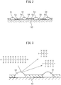
- FIG. 2 schematically shows a surface part of a catalyst carrier which is carried on a substrate of the exhaust purification catalyst 13 shown in FIG. 1 .
- a catalyst carrier 50 made of alumina on which precious metal catalysts 51 comprised of platinum Pt are carried.
- a basic layer 53 is formed which includes at least one element selected from potassium K, sodium Na, cesium Cs, or another such alkali metal, barium Ba, calcium Ca, or another such alkali earth metal, a lanthanide or another such rare earth and silver Ag, copper Cu, iron Fe, iridium Ir, or another metal able to donate electrons to NO x .
- rhodium Rh or palladium Pd may be further carried on the catalyst carrier 50 of the exhaust purification catalyst 13.
- the exhaust gas flows along the top of the catalyst carrier 50, so the precious metal catalysts 51 can be said to be carried on the exhaust gas flow surfaces of the exhaust purification catalyst 13.
- the surface of the basic layer 53 exhibits basicity, so the surface of the basic layer 53 is called the "basic exhaust gas flow surface parts 54".
- FIG. 3 schematically shows the reformation action performed at the exhaust purification catalyst 13 at this time.
- the hydrocarbons HC which are injected from the hydrocarbon feed valve 15 become radical hydrocarbons HC with a small carbon number due to the precious metal catalyst 51.
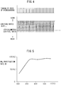
- FIG. 4 shows the feed timing of hydrocarbons from the hydrocarbon feed valve 15 and the change in the air-fuel ratio (A/F)in of the exhaust gas which flows into the exhaust purification catalyst 13.
- the change in the air-fuel ratio (A/F)in depends on the change in concentration of the hydrocarbons in the exhaust gas which flows into the exhaust purification catalyst 13, so it can be said that the change in the air-fuel ratio (A/F)in shown in FIG. 4 expresses the change in concentration of the hydrocarbons.
- the hydrocarbon concentration becomes higher, the air-fuel ratio (A/F)in becomes smaller, so, in FIG. 4 , the more to the rich side the air-fuel ratio (A/F)in becomes, the higher the hydrocarbon concentration.
- FIG. 5 shows the NO x purification rate R1 by the exhaust purification catalyst 13 with respect to the catalyst temperatures TC of the exhaust purification catalyst 13 when periodically making the concentration of hydrocarbons which flow into the exhaust purification catalyst 13 change so as to, as shown in FIG. 4 , periodically make the air-fuel ratio (A/F)in of the exhaust gas flowing to the exhaust purification catalyst 13 rich.
- A/F air-fuel ratio
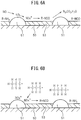
- FIGS. 6A and 6B schematically show the surface part of the catalyst carrier 50 of the exhaust purification catalyst 13.
- FIGS. 6A and 6B show the reaction which is presumed to occur when the concentration of hydrocarbons which flow into the exhaust purification catalyst 13 is made to vibrate by within a predetermined range of amplitude and within a predetermined range of period.
- FIG. 6A shows when the concentration of hydrocarbons which flow into the exhaust purification catalyst 13 is low
- FIG. 6B shows when hydrocarbons are fed from the hydrocarbon feed valve 15 and the air-fuel ratio (A/F)in of the exhaust gas flowing to the exhaust purification catalyst 13 is made rich, that is, the concentration of hydrocarbons which flow into the exhaust purification catalyst 13 becomes higher.
- the air-fuel ratio of the exhaust gas which flows into the exhaust purification catalyst 13 is maintained lean except for an instant, so the exhaust gas which flows into the exhaust purification catalyst 13 normally becomes a state of oxygen excess.
- part of the NO which is contained in the exhaust gas deposits on the exhaust purification catalyst 13, while part of the NO which is contained in the exhaust gas, as shown in FIG. 6A , is oxidized on the platinum 51 and becomes NO 2 .
- this NO 2 is further oxidized and becomes NO 3 .
- part of the NO 2 becomes NO 2 - . Therefore, on the platinum Pt 51, NO 2 - and NO 3 are produced.
- the NO which is deposited on the exhaust purification catalyst 13 and the NO 2 - and NO 3 which are formed on the platinum Pt 51 are strong in activity. Therefore, below, these NO, NO 2 - , and NO 3 will be referred to as the "active NO X *".
- the active NO X * is oxidized and is absorbed in the form of nitrate ions NO 3 - inside the basic layer 53.
- the hydrocarbon concentration around the active NO X * becomes higher, as shown in FIG. 6B , the active NO X * reacts on the platinum 51 with the radical hydrocarbons HC to thereby form the reducing intermediates.
- the reducing intermediates are adhered or adsorbed on the surface of the basic layer 53.
- the first produced reducing intermediate is considered to be a nitro compound R-NO 2 . If this nitro compound R-NO 2 is produced, the result becomes a nitrile compound R-CN, but this nitrile compound R-CN can only survive for an instant in this state, so immediately becomes an isocyanate compound R-NCO.
- This isocyanate compound R-NCO becomes an amine compound R-NH 2 if hydrolyzed. However, in this case, what is hydrolyzed is considered to be part of the isocyanate compound R-NCO. Therefore, as shown in FIG. 6B , the majority of the reducing intermediates which are held or adsorbed on the surface of the basic layer 53 is believed to be the isocyanate compound R-NCO and amine compound R-NH 2 .
- the concentration of hydrocarbons which flow into the exhaust purification catalyst 13 when the concentration of hydrocarbons which flow into the exhaust purification catalyst 13 is made higher, reducing intermediates are produced, and after the concentration of hydrocarbons which flow into the exhaust purification catalyst 13 is lowered, when the oxygen concentration is raised, the reducing intermediates react with the NO X in the exhaust gas or the active NO X * or oxygen or break down on their own whereby the NO X is removed. That is, in order for the exhaust purification catalyst 13 to remove the NO X , the concentration of hydrocarbons which flow into the exhaust purification catalyst 13 has to be periodically changed.
- the active NO X * is absorbed in the basic layer 53 in the form of nitrates without producing reducing intermediates. To avoid this, it is necessary to make the concentration of hydrocarbons which flow into the exhaust purification catalyst 13 vibrate by within a predetermined range of period.
- the precious metal catalysts 51 are carried on the exhaust gas flow surfaces of the exhaust purification catalyst 13.
- the basic exhaust gas flow surface parts 54 are formed around the precious metal catalysts 51.
- the reducing intermediates R-NCO and R-NH 2 which are held on the basic exhaust gas flow surface parts 54 are converted to N 2 , CO 2 , and H 2 O.
- the vibration period of the hydrocarbon concentration is made the vibration period required for continuation of the production of the reducing intermediates R-NCO and R-NH 2 .
- the injection interval is made 3 seconds.
- the vibration period of the hydrocarbon concentration that is, the injection period of hydrocarbons from the hydrocarbon feed valve 15
- the reducing intermediates R-NCO and R-NH 2 disappear from the surface of the basic layer 53.
- the active NO X * which is produced on the platinum Pt 53, as shown in FIG. 7A , diffuses in the basic layer 53 in the form of nitrate ions NO 3 - and becomes nitrates. That is, at this time, the NO X in the exhaust gas is absorbed in the form of nitrates inside of the basic layer 53.
- FIG. 7B shows the case where the air-fuel ratio of the exhaust gas which flows into the exhaust purification catalyst 13 is made the stoichiometric air-fuel ratio or rich when the NO x is absorbed in the form of nitrates inside of the basic layer 53.
- the oxygen concentration in the exhaust gas falls, so the reaction proceeds in the opposite direction (NO 3 - ⁇ NO 2 ), and consequently the nitrates absorbed in the basic layer 53 successively become nitrate ions NO 3 - and, as shown in FIG. 7B , are released from the basic layer 53 in the form of NO 2 .
- the released NO 2 is reduced by the hydrocarbons HC and CO contained in the exhaust gas.
- FIG. 8 shows the case of making the air-fuel ratio (A/F)in of the exhaust gas which flows into the exhaust purification catalyst 13 temporarily rich slightly before the NO X absorption ability of the basic layer 53 becomes saturated.
- the time interval of this rich control is 1 minute or more.
- the NO x which was absorbed in the basic layer 53 when the air-fuel ratio (A/F)in of the exhaust gas was lean is released all at once from the basic layer 53 and reduced when the air-fuel ratio (A/F)in of the exhaust gas is made temporarily rich. Therefore, in this case, the basic layer 53 plays the role of an absorbent for temporarily absorbing NO X .
- the basic layer 53 temporarily adsorbs the NO X . Therefore, if using term of "storage” as a term including both "absorption” and “adsorption”, at this time, the basic layer 53 performs the role of an NO X storage agent for temporarily storing the NO X .
- the exhaust purification catalyst 13 functions as an NO X storage catalyst which stores the NO X when the air-fuel ratio of the exhaust gas is lean and releases the stored NO X when the oxygen concentration in the exhaust gas falls.
- FIG. 9 shows the NO X purification rate R2 when making the exhaust purification catalyst 13 function as an NO X storage catalyst in this way.
- the abscissa of the FIG. 9 shows the catalyst temperature TC of the exhaust purification catalyst 13.
- the catalyst temperature TC is 250°C to 300°C
- an extremely high NO X purification rate is obtained, but when the catalyst temperature TC becomes a 350°C or higher high temperature, the NO X purification rate R2 falls.
- the NO X purification rate R2 falls because if the catalyst temperature TC becomes 350°C or more, NO X is less easily stored and the nitrates break down by heat and are released in the form of NO 2 from the exhaust purification catalyst 13. That is, so long as storing NO X in the form of nitrates, when the catalyst temperature TC is high, it is difficult to obtain a high NO X purification rate R2.
- nitrates are not formed or even if formed are extremely fine in amount, consequently, as shown in FIG. 5 , even when the catalyst temperature TC is high, a high NO X purification rate R1 is obtained.
- a hydrocarbon feed valve 15 for feeding hydrocarbons is arranged in the engine exhaust passage
- an exhaust purification catalyst 13 is arranged in the engine exhaust passage downstream of the hydrocarbon feed valve 15
- precious metal catalysts 51 are carried on the exhaust gas flow surfaces of the exhaust purification catalyst 13
- basic exhaust gas flow surface parts 54 are formed around the precious metal catalysts 51
- the exhaust purification catalyst 13 has the property of reducing the NO X which is contained in exhaust gas if the concentration of hydrocarbons which flow into the exhaust purification catalyst 13 is made to vibrate by within a predetermined range of amplitude and within a predetermined range of period and has the property of being increased in storage amount of NO X which is contained in exhaust gas if the vibration period of the hydrocarbon concentration is made longer than this predetermined range
- the hydrocarbons are injected from the hydrocarbon feed valve 15 within the predetermined range of period to thereby reduce the NO X which is contained in
- the NO X purification method which is shown from FIG. 4 to FIGS. 6A and 6B can be said to be a new NO X purification method designed to remove NO X without forming so much nitrates in the case of using an exhaust purification catalyst which carries precious metal catalysts and forms a basic layer which can absorb NO X .
- the nitrates which are detected from the basic layer 53 become smaller in amount compared with the case where making the exhaust purification catalyst 13 function as an NO X storage catalyst.
- this new NO X purification method will be referred to below as the "first NO X removal method".
- the injection period ⁇ T of the hydrocarbons from the hydrocarbon feed valve 15 becomes longer, the time period in which the oxygen concentration around the active NO X * becomes higher becomes longer in the time period after the hydrocarbons are injected to when the hydrocarbons are next injected.
- the injection period ⁇ T of the hydrocarbons becomes longer than about 5 seconds, the active NO X * starts to be absorbed in the form of nitrates inside the basic layer 53. Therefore, as shown in FIG. 10 , if the vibration period ⁇ T of the hydrocarbon concentration becomes longer than about 5 seconds, the NO X purification rate R1 falls. Therefore, the injection period ⁇ T of the hydrocarbons has to be made 5 seconds or less.
- the injection period ⁇ T of the hydrocarbons if the injection period ⁇ T of the hydrocarbons becomes about 0.3 second or less, the injected hydrocarbons start to build up on the exhaust gas flow surfaces of the exhaust purification catalyst 13, therefore, as shown in FIG. 10 , if the injection period ⁇ T of the hydrocarbons becomes about 0.3 second or less, the NO X purification rate R1 falls. Therefore, in the embodiment according to the present invention, the injection period of the hydrocarbons is made from 0.3 second to 5 seconds.
- the optimum hydrocarbon injection amount WT when the NO X purification action by the first NO X removal method is performed is stored as a function of the injection amount Q from fuel injectors 3 and the engine speed N in the form of a map such as shown in FIG. 11A in advance in the ROM 32.
- the optimum injection period ⁇ T of the hydrocarbons at this time is also stored as a function of the injection amount Q from the fuel injectors 3 and the engine speed N in the form of a map such as shown in FIG. 11B in advance in the ROM 32.
- an NO X purification method when making the exhaust purification catalyst 13 function as an NO X storage catalyst will be explained specifically.
- the NO X purification method in the case of making the exhaust purification catalyst 13 function as an NO X storage catalyst in this way will be referred to below as the "second NO X removal method".
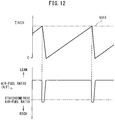
- this second NO X removal method as shown in FIG. 12 , when the stored NO X amount ⁇ NO X of NO X which is stored in the basic layer 53 exceeds a first predetermined allowable amount MAX, the air-fuel ratio (A/F)in of the exhaust gas flowing into the exhaust purification catalyst 13 is temporarily made rich. If the air-fuel ratio (A/F)in of the exhaust gas is made rich, the NO X which was stored in the basic layer 53 when the air-fuel ratio (A/F)in of the exhaust gas was lean is released from the basic layer 53 all at once and reduced. Due to this, the NO X is removed.
- the stored NO X amount ⁇ NO X is, for example, calculated from the amount of NO X which is exhausted from the engine.
- the exhausted NO X amount NOXA of NO X which is exhausted from the engine per unit time is stored as a function of the injection amount Q and engine speed N in the form of a map such as shown in FIG. 13 in advance in the ROM 32.
- the stored NO X amount ⁇ NO X is calculated from this exhausted NO X amount NOXA.
- the period at which the air-fuel ratio (A/F)in of the exhaust gas is made rich is usually 1 minute or more.
- this second NO X removal method as shown in FIG. 14 , by injecting an additional fuel WR into each combustion chamber 2 from the fuel injector 3 in addition to the combustion-use fuel Q, the air-fuel ratio (A/F)in of the exhaust gas which flows into the exhaust purification catalyst 13 is made rich.
- the abscissa indicates the crank angle.
- This additional fuel WR is injected at a timing at which it will burn, but will not appear as engine output, that is, slightly before ATDC90° after compression top dead center.
- This fuel amount WR is stored as a function of the injection amount Q and engine speed N in the form of a map such as shown in FIG. 15 in advance in the ROM 32.
- the air-fuel ratio (A/F)in of the exhaust gas flowing into the exhaust purification catalyst 13 should be made rich
- the air-fuel ratio (A/F)in of the exhaust gas discharged from the combustion chamber 2 is made rich by feeding the additional fuel WR to the combustion chamber 2.
- the additional fuel WR which is fed into the combustion chamber 2 is made to burn inside the combustion chamber 2. Therefore, inside the combustion chamber 2, at this time, rich air-fuel ratio combustion gas is generated.
- rich control which makes rich air-fuel ratio combustion gas be generated inside the cylinder and thereby makes the air-fuel ratio of the exhaust gas which flows into the exhaust purification catalyst 13 rich in this way is called "cylinder rich control".
- hydrocarbons from a hydrocarbon feed valve 15 to the exhaust gas to make the air-fuel ratio of the exhaust gas which flows into the exhaust purification catalyst 13 rich.
- rich control which feeds hydrocarbons from the hydrocarbon feed valve 15 to make the air-fuel ratio of the exhaust gas which flows into the exhaust purification catalyst 13 rich is called “exhaust rich control”.
- exhaust rich control rich control which feeds hydrocarbons from the hydrocarbon feed valve 15 to make the air-fuel ratio of the exhaust gas which flows into the exhaust purification catalyst 13 rich.
- FIG. 16 shows together the NO x purification rate R1 when an NO x removal action is performed by the first NOx removal method and an NO x purification rate R2 when an NO x removal action is performed by the second NO x removal method.
- Tm shows the temperature TC of the exhaust purification catalyst 13 when the NO x purification rate R1 and the NO x purification rate R2 become equal.
- the exhaust purification catalyst 13 stores not only NO x , but also the SO x which is contained in exhaust gas. In this case, if the amount of storage of SO x in the exhaust purification catalyst 13 increases, both the NO x purification rate R1 and NO x purification rate R2 fall. That is, when the NO x removal action by the first NO x removal method is performed, if the amount of storage of SO x increases, the exhaust gas flow surface parts 54 of the exhaust purification catalyst 13 weaken in basicity and can no longer generate and hold reducing intermediates well. As a result, the NO x purification rate R1 falls.
- the first NO x removal method can obtain a high NO x purification rate even at the time of engine high load operation where the temperature of the exhaust purification catalyst 13 becomes high. Therefore, in this embodiment according to the present invention, at the time of engine high load operation, the NO x removal action by the first NO x removal method is performed. In this regard, at the time of engine high load operation, smoke is easily generated. Therefore, if the NO x removal action by the first NOx removal method is continuously performed, deposits which are comprised of carbonized particulate etc. gradually stick on the upstream side end face of the exhaust purification catalyst 13.
- the temperature TC of the exhaust purification catalyst 13 can be raised to the SO x release temperature. That is, if the cylinder rich control is performed, light hydrocarbons are exhausted from the engine. The light hydrocarbons are sent to the exhaust purification catalyst 13. If, in this way, light hydrocarbons are sent into the exhaust purification catalyst 13, the deposits which built up at the upstream side end face of the exhaust purification catalyst 13 are burned off well by the light hydrocarbons, therefore, the temperature of the exhaust purification catalyst 13 rises.
- FIG. 17A shows the catalyst bed temperature in the exhaust purification catalyst 13 at this time. As shown in FIG.
- FIG. 17B shows the catalyst bed temperature of the exhaust purification catalyst 13 at this time. Accordingly, if the exhaust rich control is performed after the cylinder rich control is performed, it is possible to release the stored SO x from the entirety of the exhaust purification catalyst 13.
- the exhaust purification catalyst 13 has a property of reducing NO X which is contained in the exhaust gas if making a concentration of hydrocarbons flowing into the exhaust purification catalyst 13 vibrate within a predetermined range of amplitude and within a predetermined range of period and has a property of being increased in storage amount of NO X which is contained in the exhaust gas if making a vibration period of the hydrocarbon concentration longer than the predetermined range, and NO x contained in the exhaust gas is removed by injecting hydrocarbons from the hydrocarbon feed valve 15 within said predetermined range of period, as rich control for making an air-fuel ratio of an exhaust gas flowing into the exhaust purification catalyst 13 rich,
- the cylinder rich control is performed to make the air-fuel ratio of the exhaust gas flowing into the exhaust purification catalyst 13 rich until the action of release of SO x which is stored at an upstream side of the exhaust purification catalyst 13 is completed, and when the action of release of SO x which is stored at the upstream side of the exhaust purification catalyst 13 is completed, the exhaust rich control is performed to make the air-fuel ratio of the exhaust gas flowing into the exhaust purification catalyst 13 rich to release SO x which is stored at a downstream side of the exhaust purification catalyst 13.
- FIG. 18 shows a time chart of NO x purification control. Note that, in FIG. 18 , an additional fuel amount WR from the fuel injector 3, a hydrocarbon amount WT from the hydrocarbon feed valve 15, a change in the air-fuel ratio (A/F)in of the exhaust gas flowing into the exhaust purification catalyst 13, a change in the NO x storage amount ⁇ NOX in the exhaust purification catalyst 13, and a change in the SO x storage amount ⁇ SOX in the exhaust purification catalyst 13 are shown. Further, in FIGS. 18 , an allowable value MAX for the stored NO x amount and an allowable value SMAX for the stored SO x amount are shown.
- the NO x removal action is switched to the NO x removal action by the first NO x removal method from the NO x removal action by the second NO x removal method. As will be understood from FIG.
- the cylinder rich control is performed to make the air-fuel ratio (A/F)in of the exhaust gas flowing into the exhaust purification catalyst 13 rich, while when the NO x removal action by the first NO x removal method is being performed, hydrocarbons are periodically injected from the hydrocarbon feed valve 15 to periodically make the air-fuel ratio (A/F)in of the exhaust gas flowing into the exhaust purification catalyst 13 rich.
- FIG. 18 shows the case where when the NO x removal action by the first NO x removal method is being performed, the stored SO x amount ⁇ SOX exceeds the allowable value SMAX and thereby SO x release control is started.
- a time chart when this SO x release control is being performed is shown in FIG. 19 .
- FIG. 19 in FIG. 19 , an additional fuel amount WR from the fuel injector 3, a hydrocarbon amount WT from the hydrocarbon feed valve 15, a change in the air-fuel ratio (A/F)in of the exhaust gas flowing into the exhaust purification catalyst 13, an upstream side temperature TU of the exhaust purification catalyst 13, and a downstream side temperature TD of the exhaust purification catalyst 13 are shown.
- the cylinder rich control is intermittently performed. Due to this, the upstream side temperature TU of the exhaust purification catalyst 13 is made to rise to the SO x release temperature.
- the exhaust rich control is intermittently performed. Due to this, the downstream side temperature TD of the exhaust purification catalyst 13 is made to rise to the SO x release temperature.
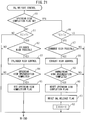
- FIG. 20 shows an exhaust purification control routine which is executed by the electronic control unit 30. This routine is executed by interruption every fixed time period. Referring to FIG. 20 , first, at step 60, it is judged if the SO x release flag showing that SO x should be released is set. If the SO x release flag showing that SO x should be released is not set, the routine proceeds to step 61 where the fuel injection amount Q multiplied with a constant value C is added to ⁇ SOX to thereby calculate the stored NO x amount ⁇ NOX which is stored in the exhaust purification catalyst 13.
- step 62 it is judged if the temperature TC of the exhaust purification catalyst 13 which is calculated based on the detected values of the temperature sensors 23 and 24 is higher than the catalyst temperature Tm which is shown in FIG. 16 .
- the routine proceeds to step 63 where the NO x removal action by the second NO x removal method is performed.
- the NO x amount NOXA which is exhausted per unit time is calculated from the map which is shown in FIG. 13 .
- the exhausted NO x amount NOXA is added to the ⁇ NOX to calculate the stored NO x amount ⁇ NOX.
- the routine proceeds to step 66 where the additional fuel amount WR is calculated from the map which is shown in FIG. 15 , next at step 66, an additional fuel injection action is performed. That is, the cylinder rich control is performed. At this time, the NO x which is stored in the exhaust purification catalyst 13 is released.
- ⁇ NOX is cleared.
- step 62 when, at step 62, it is judged that the calculated catalyst temperature TC is higher than the catalyst temperature Tm which is shown in FIG. 16 , it is judged that the NO x removal action by the first NO x removal method should be performed, then the routine proceeds to step 68 where the NO x removal action by the first NO x removal method is performed. That is, the hydrocarbon injection amount WT is calculated from FIG. 11A , the hydrocarbon injection period ⁇ T is calculated from FIG. 11B , and hydrocarbons are injected from the hydrocarbon feed valve 15 based on the calculated injection period ⁇ T and injection amount WT.
- step 69 it is judged if the stored SO x amount ⁇ SOX exceeds the allowable value SMAX. When the stored SO x amount ⁇ SOX does not exceed the allowable value SMAX, the processing cycle is ended.
- step 70 it is judged if the NO x removal action by the first NO x removal method has continued for a predetermined fixed time or more.
- the routine proceeds to step 71 where the conventionally performed SO x release treatment is performed. For example, at this time, hydrocarbons are intermittently injected from the hydrocarbon feed valve 15, that is, the exhaust rich control is intermittently performed to perform SO x release processing.
- step 70 when it is judged at step 70 that the NO x removal action by the first NO x removal method has continued for the predetermined fixed time or more, it is judged that deposits have built up on the upstream side end face of the exhaust purification catalyst 13. At this time, the routine proceeds to step 72 where the SO x release flag is set, then the routine proceeds to step 73 where SO x release control according to the present invention is performed. Once the SO x release flag is set, at the next processing cycle, the routine jumps from step 60 to step 73.
- the SO x release control which is performed at step 73 is shown in FIG. 21 .
- step 80 it is judged if the upstream side completion flag showing that the SO x release action from the upstream side of the exhaust purification catalyst 13 has been completed is set.
- the upstream side completion flag is not set, so the routine proceeds to step 81 where it is judged if the catalyst temperature TC is higher than the activation temperature T1 at which reaction is possible for the cylinder rich control, for example, 150°C or more.
- the routine proceeds to step 82 where it is judged if the operating state of the engine is an operating region where the cylinder rich control is possible.
- the operating region where the cylinder rich control is possible is shown by the hatching in FIG. 22A . As shown in FIG. 22A , this operating region where the cylinder rich control is possible is determined from the fuel injection amount Q and the engine speed N.
- step 82 When it is judged at step 82 that the operating state of the engine is in an operating region where the cylinder rich control is possible, the routine proceeds to step 83 where the cylinder rich control which is shown in FIG. 19 is performed.
- step 84 it is judged if the action of release of SO x from the upstream side of the exhaust purification catalyst 13 has been completed, for example, if the cylinder rich control has been performed continuously for a predetermined time.
- the routine proceeds to step 85 where the upstream side completion flag is set. Once the upstream side completion flag is set, at the next processing cycle, the routine proceeds from step 80 to step 86.
- step 86 it is judged if the catalyst temperature TC is higher than the activation temperature T2 at which reaction is possible for the exhaust rich control, for example, 200°C or more.
- the routine proceeds to step 87 where it is judged if the operating state of the engine is an operating range where the exhaust rich control is possible.
- the operating region in which the exhaust rich control is possible at this time is shown by the hatching in FIG. 22B . As shown in FIG. 22B , the operating region where this exhaust rich control is possible is determined from the fuel injection amount Q and the engine speed N.
- step 87 When it is judged at step 87 that the operating state of the engine is in an operating region where exhaust rich control is possible, the routine proceeds to step 88 where the exhaust rich control which is shown in FIG. 19 is performed.
- step 89 it is judged if the SO x release action from the downstream side of the exhaust purification catalyst 13 has been completed, for example, if exhaust rich control has been performed continuously for a predetermined time.
- the routine proceeds to step 90 where the upstream side completion flag is reset.
- step 91 the SO x release flag is reset, next at step 92, ⁇ SOX is cleared.
- the SO x release action from the upstream side of the exhaust purification catalyst 13 can be made to end, while when the stored SO x amount ⁇ SOX becomes less than the second predetermined value, the SO x release action from the downstream side of the exhaust purification catalyst 13 can be made to end.
- the upstream side stored SO x amount of the upstream side of the exhaust purification catalyst 13 and the downstream side stored SO x amount of the downstream side of the exhaust purification catalyst 13 are individually calculated, and when the upstream side stored SO x amount falls below a predetermined value, the SO x release action from the upstream side of the exhaust purification catalyst 13 is made to end, while when the downstream side stored SO x amount falls below a predetermined value, the SO x release action from the downstream side of the exhaust purification catalyst 13 is made to end.
- the temperature range of the exhaust purification catalyst 13 and the operating region of the engine where the cylinder rich control can be performed are predetermined.
- the cylinder rich control is performed when the temperature TC of the exhaust purification catalyst 13 and the operating state of the engine are respectively in the predetermined temperature range of the exhaust purification catalyst 13 (TC>T1) and operating region of the engine ( FIG. 22A ) where the cylinder rich control can be performed.
- the temperature range of the exhaust purification catalyst 13 and the operating region of the engine where the exhaust rich control can be performed are predetermined.
- the exhaust rich control is performed when the temperature TC of the exhaust purification catalyst 13 and the operating state of the engine are respectively in the predetermined temperature range of the exhaust purification catalyst 13 (TC>T1) and operating region of the engine ( FIG. 22B ) where yhe exhaust rich control can be performed.
- the second NO x removal method which makes the air-fuel ratio of the exhaust gas flowing into the exhaust purification catalyst 13 rich to release a stored NO x from the exhaust purification catalyst 13 when an amount of NO x stored in the exhaust purification catalyst 13 exceeds a predetermined allowable value is used.
- An NO x removal action by the first NO x removal method is performed when the temperature of the exhaust purification catalyst 13 is higher than the predetermined temperature Tm, while an NO x removal action by the second NO x removal method is performed when the temperature of the exhaust purification catalyst 13 is lower than the predetermined setting temperature Tm.
- SO x release control routine which is shown in FIG. 21 , when SO x should be released from the exhaust purification catalyst 13, if the NOX removal action by the first NOx removal method continues for a predetermined time or more, first, the cylinder rich control is performed, and then the exhaust rich control is performed to release SO x from the exhaust purification catalyst 13.
Claims (6)
- Abgasreinigungssystem eines Verbrennungsmotors (1) mit:einem Abgasreinigungskatalysator (13), welcher in einem Motorauslasskanal (12) angeordnet ist;einem Kohlenwasserstoffzulaufventil (15), welches in dem Motorauslasskanal (12) stromaufwärts des Abgasreinigungskatalysators (13) angeordnet ist; wobei:Edelmetallkatalysatoren auf Abgasströmungsflächen des Abgasreinigungskatalysators (13) getragen werden, und basische Abgasströmungsflächenteile um die Edelmetallkatalysatoren herum ausgebildet sind;der Abgasreinigungskatalysator (13) eine Eigenschaft hat, NOx, welches in dem Abgas enthalten ist, zu verringern, wenn eine Konzentration von Kohlenwasserstoffen, welche in den Abgasreinigungskatalysator (13) hinein strömen, innerhalb eines vorgegebenen Amplitudenbereichs und innerhalb eines vorgegebenen Periodenbereichs schwingt, und eine Eigenschaft hat, dass er in einer Speichermenge von NOx, welches in dem Abgas enthalten ist, erhöht wird, wenn eine Schwingungsperiode der Kohlenwasserstoffkonzentration länger als der vorgegebene Bereich ist;NOx, welches in dem Abgas enthalten ist, entfernt wird, wenn Kohlenwasserstoffe von dem Kohlenwasserstoffzulaufventil (15) innerhalb des vorgegebenen Periodenbereichs eingespritzt werden;wobei das Abgasreinigungssystem weiterhin umfasst:eine elektronische Steuereinheit (30), welche konfiguriert ist, selektiv als eine fette Steuerung, um ein Luft-Kraftstoff-Verhältnis eines Abgases, welches in den Abgasreinigungskatalysator hinein strömt, fett zu machen, eine fette Zylindersteuerung zum Erzeugen eines Verbrennungsgases mit einem fetten Luft-Kraftstoff-Verhältnis in einem Zylinder (2) und eine fette Abgassteuerung zum Zuführen von Kohlenwasserstoffen von dem Kohlenwasserstoffzulaufventil (15), um das Luft-Kraftstoff-Verhältnis des Abgases fett zu machen, zu verwenden; wobei:die elektronische Steuereinheit (30) konfiguriert ist, wenn SOx von dem Abgasreinigungskatalysator (13) freigesetzt werden sollte, zuerst die fette Zylindersteuerung durchzuführen, um die Temperatur des Abgasreinigungskatalysators (13) auf die SOx-Freisetzungstemperatur zu erhöhen, um das Luft-Kraftstoff-Verhältnis des Abgases, welches in den Abgasreinigungskatalysator (13) hinein strömt, fett zu machen, um dadurch Ablagerungen, welche sich auf einer stromaufwärtsseitigen Endfläche des Abgasreinigungskatalysators (13) aufbauen, abzubrennen, und als Nächstes die fette Abgassteuerung durchzuführen, um dadurch das Luft-Kraftstoff-Verhältnis des Abgases, welches in den Abgasreinigungskatalysator (13) hinein strömt, fett zu machen.
- Abgasreinigungssystem eines Verbrennungsmotors nach Anspruch 1, wobei die elektronische Steuereinheit (30) konfiguriert ist, die fette Zylindersteuerung durchzuführen, um das Luft-Kraftstoff-Verhältnis des Abgases, welches in den Abgasreinigungskatalysator (13) hinein strömt, fett zu machen, bis der Vorgang einer Freisetzung von SOx, welches auf einer stromaufwärtigen Seite des Abgasreinigungskatalysators (13) gespeichert ist, abgeschlossen ist, und wenn der Vorgang einer Freisetzung von SOx, welches auf der stromaufwärtigen Seite des Abgasreinigungskatalysators (13) gespeichert ist, abgeschlossen ist, die fette Abgassteuerung durchzuführen, um das Luft-Kraftstoff-Verhältnis des Abgases, welches in den Abgasreinigungskatalysator (13) hinein strömt, fett zu machen, um dadurch SOx, welches auf einer stromabwärtigen Seite des Abgasreinigungskatalysators (13) gespeichert ist, freizusetzen.
- Abgasreinigungssystem eines Verbrennungsmotors nach Anspruch 1, wobei ein Temperaturbereich des Abgasreinigungskatalysators (13) und ein Betriebsbereich des Motors (1), in welchen die fette Zylindersteuerung durchgeführt werden kann, vorgegeben sind, und, wenn die fette Zylindersteuerung durchgeführt werden muss, falls eine Temperatur des Abgasreinigungskatalysators (13) und ein Betriebszustand des Motors (1) entsprechend in dem vorgegebenen Temperaturbereich des Abgasreinigungskatalysators (13) und dem Betriebsbereich des Motors (1) sind, in welchen die fette Zylindersteuerung durchgeführt werden kann, die elektronische Steuereinheit (30) die fette Zylindersteuerung durchführt.
- Abgasreinigungssystem eines Verbrennungsmotors nach Anspruch 1, wobei ein Temperaturbereich des Abgasreinigungskatalysators (13) und ein Betriebsbereich des Motors (1), in welchen die fette Abgassteuerung durchgeführt werden kann, vorgegeben sind, und, wenn eine fette Abgassteuerung durchgeführt werden muss, falls eine Temperatur des Abgasreinigungskatalysators (13) und ein Betriebszustand des Motors (1) entsprechend in dem vorgegebenen Temperaturbereich des Abgasreinigungskatalysators (13) und dem Betriebsbereich des Motors (1) sind, in welchen die fette Abgassteuerung durchgeführt werden kann, die elektronische Steuereinheit (30) die fette Abgassteuerung durchführt.
- Abgasreinigungssystem eines Verbrennungsmotors nach Anspruch 1, wobei die elektronische Steuereinheit (30) konfiguriert ist, zusätzlich zu einem ersten NOx-Entfernungsverfahren, welches NOx, welches in dem Abgas enthalten ist, entfernt, indem Kohlenwasserstoffe von dem Kohlenwasserstoff-Zulaufventil (15) in einer Periode innerhalb des vorgegebenen Bereichs eingespritzt werden, ein zweites NOx-Entfernungsverfahren zu verwenden, welches das Luft-Kraftstoff-Verhältnis des Abgases, welches in den Abgasreinigungskatalysator (13) hinein strömt, fett macht, um dadurch gespeichertes NOx von dem Abgasreinigungskatalysator (13) freizusetzen, wenn ein Betrag von NOx, welcher in dem Abgasreinigungskatalysator (13) gespeichert ist, einen vorgegebenen erlaubten Wert überschreitet, wobei die elektronische Steuereinheit (30) konfiguriert ist, einen NOx-Entfernungsvorgang mittels des ersten NOx-Entfernungsverfahrens durchzuführen, wenn eine Temperatur des Abgasreinigungskatalysators (13) höher als eine vorgegebene Temperatur ist, und einen NOx-Entfernungsvorgang mittels des zweiten NOx-Entfernungsverfahrens durchzuführen, wenn die Temperatur des Abgasreinigungskatalysators (13) geringer als die vorgegebene Einstelltemperatur ist, und wobei die elektronische Steuereinheit (30) konfiguriert ist, wenn SOx von dem Abgasreinigungskatalysator (13) freigesetzt werden sollte, falls der NOx-Entfernungsvorgang durch das erste NOx-Entfernungsverfahren für eine vorgegebene Zeit oder mehr fortgesetzt wird, zuerst die fette Zylindersteuerung und dann die fette Abgassteuerung durchzuführen, um SOx von dem Abgasreinigungskatalysator (13) freizusetzen.
- Abgasreinigungssystem eines Verbrennungsmotors nach Anspruch 1, wobei die elektronische Steuereinheit (30) konfiguriert ist, wenn SOx von dem Abgasreinigungskatalysator (12) freigesetzt werden sollte, zuerst die fette Zylindersteuerung durchzuführen, um das Luft-Kraftstoff-Verhältnis des Abgases, welches in den Abgasreinigungskatalysator (13) hinein strömt, fett zu machen, um dadurch SOx, welches auf einer stromaufwärtigen Seite des Abgasreinigungskatalysators (13) gespeichert ist, freizusetzen, und als Nächstes die fette Abgassteuerung durchzuführen, um das Luft-Kraftstoff-Verhältnis des Abgases, welches in den Abgasreinigungskatalysator (13) hinein strömt, fett zu machen, um dadurch SOx, welches auf einer stromabwärtigen Seite des Abgasreinigungskatalysators gespeichert ist, freizusetzen.
Applications Claiming Priority (1)
| Application Number | Priority Date | Filing Date | Title |
|---|---|---|---|
| PCT/JP2013/054781 WO2014128969A1 (ja) | 2013-02-25 | 2013-02-25 | 内燃機関の排気浄化装置 |
Publications (3)
| Publication Number | Publication Date |
|---|---|
| EP2960455A1 EP2960455A1 (de) | 2015-12-30 |
| EP2960455A4 EP2960455A4 (de) | 2016-02-24 |
| EP2960455B1 true EP2960455B1 (de) | 2018-01-17 |
Family
ID=51390792
Family Applications (1)
| Application Number | Title | Priority Date | Filing Date |
|---|---|---|---|
| EP13876028.5A Active EP2960455B1 (de) | 2013-02-25 | 2013-02-25 | Abgasreinigungsvorrichtung für einen verbrennungsmotor |
Country Status (5)
| Country | Link |
|---|---|
| US (1) | US9453445B2 (de) |
| EP (1) | EP2960455B1 (de) |
| JP (1) | JP5880776B2 (de) |
| CN (1) | CN105026715B (de) |
| WO (1) | WO2014128969A1 (de) |
Families Citing this family (4)
| Publication number | Priority date | Publication date | Assignee | Title |
|---|---|---|---|---|
| JP6358191B2 (ja) | 2015-08-17 | 2018-07-18 | トヨタ自動車株式会社 | 内燃機関の制御装置 |
| JP6369421B2 (ja) | 2015-08-21 | 2018-08-08 | トヨタ自動車株式会社 | 内燃機関の排気浄化装置 |
| US10378405B2 (en) | 2016-01-20 | 2019-08-13 | Deere & Company | Method for managing temperatures in aftertreatment system |
| JP6806025B2 (ja) * | 2017-10-11 | 2020-12-23 | トヨタ自動車株式会社 | エンジン制御装置 |
Family Cites Families (12)
| Publication number | Priority date | Publication date | Assignee | Title |
|---|---|---|---|---|
| JP3815289B2 (ja) * | 2001-10-19 | 2006-08-30 | トヨタ自動車株式会社 | 内燃機関の排気浄化装置 |
| JP4635860B2 (ja) | 2005-12-20 | 2011-02-23 | 株式会社デンソー | 内燃機関の排気浄化装置 |
| US8534051B2 (en) * | 2007-12-26 | 2013-09-17 | Toyota Jidosha Kabushiki Kaisha | Exhaust purification device of internal combustion engine |
| JP4998326B2 (ja) * | 2008-02-27 | 2012-08-15 | いすゞ自動車株式会社 | 排気ガス浄化システムの制御方法及び排気ガス浄化システム |
| JP2010019092A (ja) | 2008-07-08 | 2010-01-28 | Toyota Motor Corp | 内燃機関の排気浄化装置 |
| JP5323506B2 (ja) * | 2009-01-16 | 2013-10-23 | 日野自動車株式会社 | パティキュレートフィルタの再生方法 |
| WO2010113278A1 (ja) * | 2009-03-31 | 2010-10-07 | トヨタ自動車株式会社 | 内燃機関の排気浄化システム |
| CA2750738C (en) | 2010-03-15 | 2014-04-29 | Toyota Jidosha Kabushiki Kaisha | Exhaust purification system of internal combustion engine |
| EP2460995B1 (de) * | 2010-03-23 | 2016-03-23 | Toyota Jidosha Kabushiki Kaisha | Abgasreiniger für einen verbrennungsmotor |
| JP5067511B2 (ja) * | 2010-08-30 | 2012-11-07 | トヨタ自動車株式会社 | 内燃機関の排気浄化装置 |
| CN103534449B (zh) * | 2011-01-17 | 2016-02-03 | 丰田自动车株式会社 | 内燃机的排气净化装置 |
| JP5152417B2 (ja) * | 2011-03-17 | 2013-02-27 | トヨタ自動車株式会社 | 内燃機関の排気浄化装置 |
-
2013
- 2013-02-25 CN CN201380073518.1A patent/CN105026715B/zh active Active
- 2013-02-25 US US14/764,110 patent/US9453445B2/en active Active
- 2013-02-25 EP EP13876028.5A patent/EP2960455B1/de active Active
- 2013-02-25 JP JP2015501231A patent/JP5880776B2/ja active Active
- 2013-02-25 WO PCT/JP2013/054781 patent/WO2014128969A1/ja active Application Filing
Non-Patent Citations (1)
| Title |
|---|
| None * |
Also Published As
| Publication number | Publication date |
|---|---|
| EP2960455A1 (de) | 2015-12-30 |
| JPWO2014128969A1 (ja) | 2017-02-02 |
| JP5880776B2 (ja) | 2016-03-09 |
| US9453445B2 (en) | 2016-09-27 |
| EP2960455A4 (de) | 2016-02-24 |
| WO2014128969A1 (ja) | 2014-08-28 |
| US20160010527A1 (en) | 2016-01-14 |
| CN105026715B (zh) | 2017-08-22 |
| CN105026715A (zh) | 2015-11-04 |
Similar Documents
| Publication | Publication Date | Title |
|---|---|---|
| EP2610450B1 (de) | NOx-REINIGUNGSVERFAHREN EINES ABGASREINIGUNGSSYSTEMS EINER VERBRENNUNGSKRAFTMASCHINE | |
| US9021788B2 (en) | Exhaust purification system of internal combustion engine | |
| US9109491B2 (en) | Exhaust purification system of internal combustion engine | |
| EP2541009B1 (de) | Abgasreiniger für einen verbrennungsmotor | |
| EP3039258B1 (de) | Verfahren zum reinigen von abgas | |
| EP2460998A1 (de) | Abgasreinigungsvorrichtung für einen verbrennungsmotor | |
| EP2955348B1 (de) | Abgasreinigungssystem eines verbrennungsmotors | |
| EP2960455B1 (de) | Abgasreinigungsvorrichtung für einen verbrennungsmotor | |
| EP3039259B9 (de) | Abgasreinigungssystem für einen verbrennungsmotor | |
| EP2511493B1 (de) | Abgasreinigungssystem für einen verbrennungsmotor | |
| EP3030763B1 (de) | Abgasreinigungsvorrichtung für einen verbrennungsmotor | |
| US9567889B2 (en) | Exhaust purification system for internal combustion engine | |
| EP2873818B1 (de) | Abgasreinigungssystem eines verbrennungsmotors | |
| EP2530267B1 (de) | Verfahren zur abgasreinigung in einer abgasreinigungsvorrichtung eines verbrennungsmotors | |
| EP3036412B1 (de) | Abgasreinigungsvorrichtung für einen verbrennungsmotor | |
| EP2835509B1 (de) | Abgasreinigungssystem für einen Verbrennungsmotor |
Legal Events
| Date | Code | Title | Description |
|---|---|---|---|
| PUAI | Public reference made under article 153(3) epc to a published international application that has entered the european phase |
Free format text: ORIGINAL CODE: 0009012 |
|
| 17P | Request for examination filed |
Effective date: 20150527 |
|
| AK | Designated contracting states |
Kind code of ref document: A1 Designated state(s): AL AT BE BG CH CY CZ DE DK EE ES FI FR GB GR HR HU IE IS IT LI LT LU LV MC MK MT NL NO PL PT RO RS SE SI SK SM TR |
|
| AX | Request for extension of the european patent |
Extension state: BA ME |
|
| A4 | Supplementary search report drawn up and despatched |
Effective date: 20160126 |
|
| RIC1 | Information provided on ipc code assigned before grant |
Ipc: F02D 41/02 20060101ALI20160120BHEP Ipc: F02D 41/14 20060101ALI20160120BHEP Ipc: F01N 3/08 20060101ALI20160120BHEP Ipc: F01N 3/20 20060101AFI20160120BHEP Ipc: F01N 9/00 20060101ALI20160120BHEP Ipc: F01N 3/36 20060101ALI20160120BHEP |
|
| DAX | Request for extension of the european patent (deleted) | ||
| GRAP | Despatch of communication of intention to grant a patent |
Free format text: ORIGINAL CODE: EPIDOSNIGR1 |
|
| STAA | Information on the status of an ep patent application or granted ep patent |
Free format text: STATUS: GRANT OF PATENT IS INTENDED |
|
| INTG | Intention to grant announced |
Effective date: 20170921 |
|
| GRAS | Grant fee paid |
Free format text: ORIGINAL CODE: EPIDOSNIGR3 |
|
| GRAA | (expected) grant |
Free format text: ORIGINAL CODE: 0009210 |
|
| STAA | Information on the status of an ep patent application or granted ep patent |
Free format text: STATUS: THE PATENT HAS BEEN GRANTED |
|
| AK | Designated contracting states |
Kind code of ref document: B1 Designated state(s): AL AT BE BG CH CY CZ DE DK EE ES FI FR GB GR HR HU IE IS IT LI LT LU LV MC MK MT NL NO PL PT RO RS SE SI SK SM TR |
|
| REG | Reference to a national code |
Ref country code: GB Ref legal event code: FG4D |
|
| REG | Reference to a national code |
Ref country code: CH Ref legal event code: EP |
|
| REG | Reference to a national code |
Ref country code: IE Ref legal event code: FG4D |
|
| REG | Reference to a national code |
Ref country code: AT Ref legal event code: REF Ref document number: 964594 Country of ref document: AT Kind code of ref document: T Effective date: 20180215 |
|
| REG | Reference to a national code |
Ref country code: DE Ref legal event code: R096 Ref document number: 602013032436 Country of ref document: DE |
|
| REG | Reference to a national code |
Ref country code: FR Ref legal event code: PLFP Year of fee payment: 6 |
|
| REG | Reference to a national code |
Ref country code: NL Ref legal event code: MP Effective date: 20180117 |
|
| REG | Reference to a national code |
Ref country code: LT Ref legal event code: MG4D |
|
| REG | Reference to a national code |
Ref country code: AT Ref legal event code: MK05 Ref document number: 964594 Country of ref document: AT Kind code of ref document: T Effective date: 20180117 |
|
| PG25 | Lapsed in a contracting state [announced via postgrant information from national office to epo] |
Ref country code: NL Free format text: LAPSE BECAUSE OF FAILURE TO SUBMIT A TRANSLATION OF THE DESCRIPTION OR TO PAY THE FEE WITHIN THE PRESCRIBED TIME-LIMIT Effective date: 20180117 |
|
| PG25 | Lapsed in a contracting state [announced via postgrant information from national office to epo] |
Ref country code: CY Free format text: LAPSE BECAUSE OF FAILURE TO SUBMIT A TRANSLATION OF THE DESCRIPTION OR TO PAY THE FEE WITHIN THE PRESCRIBED TIME-LIMIT Effective date: 20180117 Ref country code: NO Free format text: LAPSE BECAUSE OF FAILURE TO SUBMIT A TRANSLATION OF THE DESCRIPTION OR TO PAY THE FEE WITHIN THE PRESCRIBED TIME-LIMIT Effective date: 20180417 Ref country code: ES Free format text: LAPSE BECAUSE OF FAILURE TO SUBMIT A TRANSLATION OF THE DESCRIPTION OR TO PAY THE FEE WITHIN THE PRESCRIBED TIME-LIMIT Effective date: 20180117 Ref country code: FI Free format text: LAPSE BECAUSE OF FAILURE TO SUBMIT A TRANSLATION OF THE DESCRIPTION OR TO PAY THE FEE WITHIN THE PRESCRIBED TIME-LIMIT Effective date: 20180117 Ref country code: LT Free format text: LAPSE BECAUSE OF FAILURE TO SUBMIT A TRANSLATION OF THE DESCRIPTION OR TO PAY THE FEE WITHIN THE PRESCRIBED TIME-LIMIT Effective date: 20180117 Ref country code: HR Free format text: LAPSE BECAUSE OF FAILURE TO SUBMIT A TRANSLATION OF THE DESCRIPTION OR TO PAY THE FEE WITHIN THE PRESCRIBED TIME-LIMIT Effective date: 20180117 |
|
| PG25 | Lapsed in a contracting state [announced via postgrant information from national office to epo] |
Ref country code: BG Free format text: LAPSE BECAUSE OF FAILURE TO SUBMIT A TRANSLATION OF THE DESCRIPTION OR TO PAY THE FEE WITHIN THE PRESCRIBED TIME-LIMIT Effective date: 20180417 Ref country code: IS Free format text: LAPSE BECAUSE OF FAILURE TO SUBMIT A TRANSLATION OF THE DESCRIPTION OR TO PAY THE FEE WITHIN THE PRESCRIBED TIME-LIMIT Effective date: 20180517 Ref country code: GR Free format text: LAPSE BECAUSE OF FAILURE TO SUBMIT A TRANSLATION OF THE DESCRIPTION OR TO PAY THE FEE WITHIN THE PRESCRIBED TIME-LIMIT Effective date: 20180418 Ref country code: PL Free format text: LAPSE BECAUSE OF FAILURE TO SUBMIT A TRANSLATION OF THE DESCRIPTION OR TO PAY THE FEE WITHIN THE PRESCRIBED TIME-LIMIT Effective date: 20180117 Ref country code: RS Free format text: LAPSE BECAUSE OF FAILURE TO SUBMIT A TRANSLATION OF THE DESCRIPTION OR TO PAY THE FEE WITHIN THE PRESCRIBED TIME-LIMIT Effective date: 20180117 Ref country code: AT Free format text: LAPSE BECAUSE OF FAILURE TO SUBMIT A TRANSLATION OF THE DESCRIPTION OR TO PAY THE FEE WITHIN THE PRESCRIBED TIME-LIMIT Effective date: 20180117 Ref country code: LV Free format text: LAPSE BECAUSE OF FAILURE TO SUBMIT A TRANSLATION OF THE DESCRIPTION OR TO PAY THE FEE WITHIN THE PRESCRIBED TIME-LIMIT Effective date: 20180117 Ref country code: SE Free format text: LAPSE BECAUSE OF FAILURE TO SUBMIT A TRANSLATION OF THE DESCRIPTION OR TO PAY THE FEE WITHIN THE PRESCRIBED TIME-LIMIT Effective date: 20180117 |
|
| REG | Reference to a national code |
Ref country code: CH Ref legal event code: PL |
|
| REG | Reference to a national code |
Ref country code: DE Ref legal event code: R084 Ref document number: 602013032436 Country of ref document: DE |
|
| REG | Reference to a national code |
Ref country code: DE Ref legal event code: R097 Ref document number: 602013032436 Country of ref document: DE |
|
| PG25 | Lapsed in a contracting state [announced via postgrant information from national office to epo] |
Ref country code: RO Free format text: LAPSE BECAUSE OF FAILURE TO SUBMIT A TRANSLATION OF THE DESCRIPTION OR TO PAY THE FEE WITHIN THE PRESCRIBED TIME-LIMIT Effective date: 20180117 Ref country code: EE Free format text: LAPSE BECAUSE OF FAILURE TO SUBMIT A TRANSLATION OF THE DESCRIPTION OR TO PAY THE FEE WITHIN THE PRESCRIBED TIME-LIMIT Effective date: 20180117 Ref country code: MC Free format text: LAPSE BECAUSE OF FAILURE TO SUBMIT A TRANSLATION OF THE DESCRIPTION OR TO PAY THE FEE WITHIN THE PRESCRIBED TIME-LIMIT Effective date: 20180117 Ref country code: AL Free format text: LAPSE BECAUSE OF FAILURE TO SUBMIT A TRANSLATION OF THE DESCRIPTION OR TO PAY THE FEE WITHIN THE PRESCRIBED TIME-LIMIT Effective date: 20180117 |
|
| PLBE | No opposition filed within time limit |
Free format text: ORIGINAL CODE: 0009261 |
|
| STAA | Information on the status of an ep patent application or granted ep patent |
Free format text: STATUS: NO OPPOSITION FILED WITHIN TIME LIMIT |
|
| REG | Reference to a national code |
Ref country code: IE Ref legal event code: MM4A |
|
| REG | Reference to a national code |
Ref country code: BE Ref legal event code: MM Effective date: 20180228 |
|
| PG25 | Lapsed in a contracting state [announced via postgrant information from national office to epo] |
Ref country code: DK Free format text: LAPSE BECAUSE OF FAILURE TO SUBMIT A TRANSLATION OF THE DESCRIPTION OR TO PAY THE FEE WITHIN THE PRESCRIBED TIME-LIMIT Effective date: 20180117 Ref country code: SM Free format text: LAPSE BECAUSE OF FAILURE TO SUBMIT A TRANSLATION OF THE DESCRIPTION OR TO PAY THE FEE WITHIN THE PRESCRIBED TIME-LIMIT Effective date: 20180117 Ref country code: LU Free format text: LAPSE BECAUSE OF NON-PAYMENT OF DUE FEES Effective date: 20180225 Ref country code: CZ Free format text: LAPSE BECAUSE OF FAILURE TO SUBMIT A TRANSLATION OF THE DESCRIPTION OR TO PAY THE FEE WITHIN THE PRESCRIBED TIME-LIMIT Effective date: 20180117 Ref country code: LI Free format text: LAPSE BECAUSE OF NON-PAYMENT OF DUE FEES Effective date: 20180228 Ref country code: SK Free format text: LAPSE BECAUSE OF FAILURE TO SUBMIT A TRANSLATION OF THE DESCRIPTION OR TO PAY THE FEE WITHIN THE PRESCRIBED TIME-LIMIT Effective date: 20180117 Ref country code: CH Free format text: LAPSE BECAUSE OF NON-PAYMENT OF DUE FEES Effective date: 20180228 |
|
| 26N | No opposition filed |
Effective date: 20181018 |
|
| GBPC | Gb: european patent ceased through non-payment of renewal fee |
Effective date: 20180417 |
|
| PG25 | Lapsed in a contracting state [announced via postgrant information from national office to epo] |
Ref country code: IE Free format text: LAPSE BECAUSE OF NON-PAYMENT OF DUE FEES Effective date: 20180225 |
|
| PG25 | Lapsed in a contracting state [announced via postgrant information from national office to epo] |
Ref country code: GB Free format text: LAPSE BECAUSE OF NON-PAYMENT OF DUE FEES Effective date: 20180417 Ref country code: BE Free format text: LAPSE BECAUSE OF NON-PAYMENT OF DUE FEES Effective date: 20180228 Ref country code: SI Free format text: LAPSE BECAUSE OF FAILURE TO SUBMIT A TRANSLATION OF THE DESCRIPTION OR TO PAY THE FEE WITHIN THE PRESCRIBED TIME-LIMIT Effective date: 20180117 |
|
| PG25 | Lapsed in a contracting state [announced via postgrant information from national office to epo] |
Ref country code: MT Free format text: LAPSE BECAUSE OF NON-PAYMENT OF DUE FEES Effective date: 20180225 |
|
| PG25 | Lapsed in a contracting state [announced via postgrant information from national office to epo] |
Ref country code: TR Free format text: LAPSE BECAUSE OF FAILURE TO SUBMIT A TRANSLATION OF THE DESCRIPTION OR TO PAY THE FEE WITHIN THE PRESCRIBED TIME-LIMIT Effective date: 20180117 |
|
| PG25 | Lapsed in a contracting state [announced via postgrant information from national office to epo] |
Ref country code: PT Free format text: LAPSE BECAUSE OF FAILURE TO SUBMIT A TRANSLATION OF THE DESCRIPTION OR TO PAY THE FEE WITHIN THE PRESCRIBED TIME-LIMIT Effective date: 20180117 |
|
| PG25 | Lapsed in a contracting state [announced via postgrant information from national office to epo] |
Ref country code: MK Free format text: LAPSE BECAUSE OF NON-PAYMENT OF DUE FEES Effective date: 20180117 Ref country code: HU Free format text: LAPSE BECAUSE OF FAILURE TO SUBMIT A TRANSLATION OF THE DESCRIPTION OR TO PAY THE FEE WITHIN THE PRESCRIBED TIME-LIMIT; INVALID AB INITIO Effective date: 20130225 |
|
| PGFP | Annual fee paid to national office [announced via postgrant information from national office to epo] |
Ref country code: FR Payment date: 20230110 Year of fee payment: 11 |
|
| PGFP | Annual fee paid to national office [announced via postgrant information from national office to epo] |
Ref country code: IT Payment date: 20230110 Year of fee payment: 11 Ref country code: DE Payment date: 20221230 Year of fee payment: 11 |
|
| P01 | Opt-out of the competence of the unified patent court (upc) registered |
Effective date: 20230427 |