EP2987619A1 - Remplisseuse de moule et procédé de démoulage et de remplissage de récipients - Google Patents
Remplisseuse de moule et procédé de démoulage et de remplissage de récipients Download PDFInfo
- Publication number
- EP2987619A1 EP2987619A1 EP14181660.3A EP14181660A EP2987619A1 EP 2987619 A1 EP2987619 A1 EP 2987619A1 EP 14181660 A EP14181660 A EP 14181660A EP 2987619 A1 EP2987619 A1 EP 2987619A1
- Authority
- EP
- European Patent Office
- Prior art keywords
- filling
- mold
- product
- temperature
- plastic container
- Prior art date
- Legal status (The legal status is an assumption and is not a legal conclusion. Google has not performed a legal analysis and makes no representation as to the accuracy of the status listed.)
- Withdrawn
Links
- 238000011049 filling Methods 0.000 title claims abstract description 288
- 238000000034 method Methods 0.000 title claims abstract description 30
- 238000000465 moulding Methods 0.000 title claims description 46
- 238000004519 manufacturing process Methods 0.000 claims abstract description 10
- 238000010438 heat treatment Methods 0.000 claims description 22
- 238000007664 blowing Methods 0.000 claims description 20
- 238000003303 reheating Methods 0.000 claims 1
- 239000000047 product Substances 0.000 description 178
- 239000007788 liquid Substances 0.000 description 41
- 238000011161 development Methods 0.000 description 29
- 230000018109 developmental process Effects 0.000 description 29
- 239000007789 gas Substances 0.000 description 21
- 238000001816 cooling Methods 0.000 description 15
- 239000012530 fluid Substances 0.000 description 13
- 230000001105 regulatory effect Effects 0.000 description 11
- XLYOFNOQVPJJNP-UHFFFAOYSA-N water Substances O XLYOFNOQVPJJNP-UHFFFAOYSA-N 0.000 description 9
- 239000000463 material Substances 0.000 description 8
- CURLTUGMZLYLDI-UHFFFAOYSA-N Carbon dioxide Chemical compound O=C=O CURLTUGMZLYLDI-UHFFFAOYSA-N 0.000 description 7
- 238000002156 mixing Methods 0.000 description 7
- 235000014171 carbonated beverage Nutrition 0.000 description 5
- 238000011109 contamination Methods 0.000 description 5
- 238000002425 crystallisation Methods 0.000 description 5
- 230000008025 crystallization Effects 0.000 description 5
- 235000013361 beverage Nutrition 0.000 description 4
- 239000011261 inert gas Substances 0.000 description 4
- 238000007493 shaping process Methods 0.000 description 4
- 238000003860 storage Methods 0.000 description 4
- 230000002087 whitening effect Effects 0.000 description 4
- MHAJPDPJQMAIIY-UHFFFAOYSA-N Hydrogen peroxide Chemical compound OO MHAJPDPJQMAIIY-UHFFFAOYSA-N 0.000 description 3
- 230000008901 benefit Effects 0.000 description 3
- 238000004659 sterilization and disinfection Methods 0.000 description 3
- 238000011144 upstream manufacturing Methods 0.000 description 3
- 235000013405 beer Nutrition 0.000 description 2
- 230000033228 biological regulation Effects 0.000 description 2
- 230000001276 controlling effect Effects 0.000 description 2
- 230000009477 glass transition Effects 0.000 description 2
- 229910052500 inorganic mineral Inorganic materials 0.000 description 2
- 239000011707 mineral Substances 0.000 description 2
- 238000010943 off-gassing Methods 0.000 description 2
- 239000007787 solid Substances 0.000 description 2
- 230000001954 sterilising effect Effects 0.000 description 2
- 241001295925 Gegenes Species 0.000 description 1
- 241001122767 Theaceae Species 0.000 description 1
- 239000002253 acid Substances 0.000 description 1
- QVGXLLKOCUKJST-UHFFFAOYSA-N atomic oxygen Chemical compound [O] QVGXLLKOCUKJST-UHFFFAOYSA-N 0.000 description 1
- 238000000071 blow moulding Methods 0.000 description 1
- 229910002092 carbon dioxide Inorganic materials 0.000 description 1
- 239000001569 carbon dioxide Substances 0.000 description 1
- 235000012174 carbonated soft drink Nutrition 0.000 description 1
- 238000004140 cleaning Methods 0.000 description 1
- 238000005202 decontamination Methods 0.000 description 1
- 230000003588 decontaminative effect Effects 0.000 description 1
- 230000007423 decrease Effects 0.000 description 1
- 238000013461 design Methods 0.000 description 1
- 235000013399 edible fruits Nutrition 0.000 description 1
- 239000000839 emulsion Substances 0.000 description 1
- 238000005265 energy consumption Methods 0.000 description 1
- 238000000605 extraction Methods 0.000 description 1
- 239000012467 final product Substances 0.000 description 1
- 238000009472 formulation Methods 0.000 description 1
- 235000015203 fruit juice Nutrition 0.000 description 1
- 235000011389 fruit/vegetable juice Nutrition 0.000 description 1
- 238000002347 injection Methods 0.000 description 1
- 239000007924 injection Substances 0.000 description 1
- 238000001746 injection moulding Methods 0.000 description 1
- 238000002372 labelling Methods 0.000 description 1
- 239000012263 liquid product Substances 0.000 description 1
- 239000000203 mixture Substances 0.000 description 1
- 238000012986 modification Methods 0.000 description 1
- 230000004048 modification Effects 0.000 description 1
- 239000001301 oxygen Substances 0.000 description 1
- 229910052760 oxygen Inorganic materials 0.000 description 1
- 229920000728 polyester Polymers 0.000 description 1
- 230000002028 premature Effects 0.000 description 1
- 239000000523 sample Substances 0.000 description 1
- 238000007789 sealing Methods 0.000 description 1
- 235000014214 soft drink Nutrition 0.000 description 1
- 238000005507 spraying Methods 0.000 description 1
- 238000010025 steaming Methods 0.000 description 1
- 239000006188 syrup Substances 0.000 description 1
- 235000020357 syrup Nutrition 0.000 description 1
- 238000012360 testing method Methods 0.000 description 1
- 238000012549 training Methods 0.000 description 1
- 238000012546 transfer Methods 0.000 description 1
- 239000003643 water by type Substances 0.000 description 1
- 238000005303 weighing Methods 0.000 description 1
Images


Classifications
-
- B—PERFORMING OPERATIONS; TRANSPORTING
- B29—WORKING OF PLASTICS; WORKING OF SUBSTANCES IN A PLASTIC STATE IN GENERAL
- B29C—SHAPING OR JOINING OF PLASTICS; SHAPING OF MATERIAL IN A PLASTIC STATE, NOT OTHERWISE PROVIDED FOR; AFTER-TREATMENT OF THE SHAPED PRODUCTS, e.g. REPAIRING
- B29C49/00—Blow-moulding, i.e. blowing a preform or parison to a desired shape within a mould; Apparatus therefor
- B29C49/42—Component parts, details or accessories; Auxiliary operations
- B29C49/46—Component parts, details or accessories; Auxiliary operations characterised by using particular environment or blow fluids other than air
-
- B—PERFORMING OPERATIONS; TRANSPORTING
- B29—WORKING OF PLASTICS; WORKING OF SUBSTANCES IN A PLASTIC STATE IN GENERAL
- B29C—SHAPING OR JOINING OF PLASTICS; SHAPING OF MATERIAL IN A PLASTIC STATE, NOT OTHERWISE PROVIDED FOR; AFTER-TREATMENT OF THE SHAPED PRODUCTS, e.g. REPAIRING
- B29C49/00—Blow-moulding, i.e. blowing a preform or parison to a desired shape within a mould; Apparatus therefor
- B29C49/42—Component parts, details or accessories; Auxiliary operations
- B29C49/4289—Valve constructions or configurations, e.g. arranged to reduce blowing fluid consumption
-
- B—PERFORMING OPERATIONS; TRANSPORTING
- B65—CONVEYING; PACKING; STORING; HANDLING THIN OR FILAMENTARY MATERIAL
- B65B—MACHINES, APPARATUS OR DEVICES FOR, OR METHODS OF, PACKAGING ARTICLES OR MATERIALS; UNPACKING
- B65B3/00—Packaging plastic material, semiliquids, liquids or mixed solids and liquids, in individual containers or receptacles, e.g. bags, sacks, boxes, cartons, cans, or jars
- B65B3/02—Machines characterised by the incorporation of means for making the containers or receptacles
- B65B3/022—Making containers by moulding of a thermoplastic material
-
- B—PERFORMING OPERATIONS; TRANSPORTING
- B65—CONVEYING; PACKING; STORING; HANDLING THIN OR FILAMENTARY MATERIAL
- B65B—MACHINES, APPARATUS OR DEVICES FOR, OR METHODS OF, PACKAGING ARTICLES OR MATERIALS; UNPACKING
- B65B3/00—Packaging plastic material, semiliquids, liquids or mixed solids and liquids, in individual containers or receptacles, e.g. bags, sacks, boxes, cartons, cans, or jars
- B65B3/18—Controlling escape of air from containers or receptacles during filling
-
- B—PERFORMING OPERATIONS; TRANSPORTING
- B65—CONVEYING; PACKING; STORING; HANDLING THIN OR FILAMENTARY MATERIAL
- B65B—MACHINES, APPARATUS OR DEVICES FOR, OR METHODS OF, PACKAGING ARTICLES OR MATERIALS; UNPACKING
- B65B3/00—Packaging plastic material, semiliquids, liquids or mixed solids and liquids, in individual containers or receptacles, e.g. bags, sacks, boxes, cartons, cans, or jars
- B65B3/26—Methods or devices for controlling the quantity of the material fed or filled
- B65B3/30—Methods or devices for controlling the quantity of the material fed or filled by volumetric measurement
- B65B3/32—Methods or devices for controlling the quantity of the material fed or filled by volumetric measurement by pistons co-operating with measuring chambers
-
- B—PERFORMING OPERATIONS; TRANSPORTING
- B65—CONVEYING; PACKING; STORING; HANDLING THIN OR FILAMENTARY MATERIAL
- B65B—MACHINES, APPARATUS OR DEVICES FOR, OR METHODS OF, PACKAGING ARTICLES OR MATERIALS; UNPACKING
- B65B31/00—Packaging articles or materials under special atmospheric or gaseous conditions; Adding propellants to aerosol containers
- B65B31/04—Evacuating, pressurising or gasifying filled containers or wrappers by means of nozzles through which air or other gas, e.g. an inert gas, is withdrawn or supplied
- B65B31/041—Evacuating, pressurising or gasifying filled containers or wrappers by means of nozzles through which air or other gas, e.g. an inert gas, is withdrawn or supplied the nozzles acting from above on containers or wrappers open at their top
- B65B31/042—Evacuating, pressurising or gasifying filled containers or wrappers by means of nozzles through which air or other gas, e.g. an inert gas, is withdrawn or supplied the nozzles acting from above on containers or wrappers open at their top the nozzles being arranged for insertion into, and withdrawal from, the container or wrapper
-
- B—PERFORMING OPERATIONS; TRANSPORTING
- B65—CONVEYING; PACKING; STORING; HANDLING THIN OR FILAMENTARY MATERIAL
- B65B—MACHINES, APPARATUS OR DEVICES FOR, OR METHODS OF, PACKAGING ARTICLES OR MATERIALS; UNPACKING
- B65B31/00—Packaging articles or materials under special atmospheric or gaseous conditions; Adding propellants to aerosol containers
- B65B31/04—Evacuating, pressurising or gasifying filled containers or wrappers by means of nozzles through which air or other gas, e.g. an inert gas, is withdrawn or supplied
- B65B31/044—Evacuating, pressurising or gasifying filled containers or wrappers by means of nozzles through which air or other gas, e.g. an inert gas, is withdrawn or supplied the nozzles being combined with a filling device
-
- B—PERFORMING OPERATIONS; TRANSPORTING
- B65—CONVEYING; PACKING; STORING; HANDLING THIN OR FILAMENTARY MATERIAL
- B65B—MACHINES, APPARATUS OR DEVICES FOR, OR METHODS OF, PACKAGING ARTICLES OR MATERIALS; UNPACKING
- B65B39/00—Nozzles, funnels or guides for introducing articles or materials into containers or wrappers
- B65B39/14—Nozzles, funnels or guides for introducing articles or materials into containers or wrappers movable with a moving container or wrapper during filling or depositing
- B65B39/145—Nozzles, funnels or guides for introducing articles or materials into containers or wrappers movable with a moving container or wrapper during filling or depositing in an endless path
-
- B—PERFORMING OPERATIONS; TRANSPORTING
- B65—CONVEYING; PACKING; STORING; HANDLING THIN OR FILAMENTARY MATERIAL
- B65B—MACHINES, APPARATUS OR DEVICES FOR, OR METHODS OF, PACKAGING ARTICLES OR MATERIALS; UNPACKING
- B65B63/00—Auxiliary devices, not otherwise provided for, for operating on articles or materials to be packaged
- B65B63/08—Auxiliary devices, not otherwise provided for, for operating on articles or materials to be packaged for heating or cooling articles or materials to facilitate packaging
-
- B—PERFORMING OPERATIONS; TRANSPORTING
- B29—WORKING OF PLASTICS; WORKING OF SUBSTANCES IN A PLASTIC STATE IN GENERAL
- B29C—SHAPING OR JOINING OF PLASTICS; SHAPING OF MATERIAL IN A PLASTIC STATE, NOT OTHERWISE PROVIDED FOR; AFTER-TREATMENT OF THE SHAPED PRODUCTS, e.g. REPAIRING
- B29C49/00—Blow-moulding, i.e. blowing a preform or parison to a desired shape within a mould; Apparatus therefor
- B29C49/42—Component parts, details or accessories; Auxiliary operations
- B29C49/46—Component parts, details or accessories; Auxiliary operations characterised by using particular environment or blow fluids other than air
- B29C2049/4602—Blowing fluids
- B29C2049/465—Blowing fluids being incompressible
- B29C2049/4652—Blowing fluids being incompressible hot liquids
-
- B—PERFORMING OPERATIONS; TRANSPORTING
- B29—WORKING OF PLASTICS; WORKING OF SUBSTANCES IN A PLASTIC STATE IN GENERAL
- B29C—SHAPING OR JOINING OF PLASTICS; SHAPING OF MATERIAL IN A PLASTIC STATE, NOT OTHERWISE PROVIDED FOR; AFTER-TREATMENT OF THE SHAPED PRODUCTS, e.g. REPAIRING
- B29C49/00—Blow-moulding, i.e. blowing a preform or parison to a desired shape within a mould; Apparatus therefor
- B29C49/42—Component parts, details or accessories; Auxiliary operations
- B29C49/46—Component parts, details or accessories; Auxiliary operations characterised by using particular environment or blow fluids other than air
- B29C2049/4602—Blowing fluids
- B29C2049/465—Blowing fluids being incompressible
- B29C2049/4664—Blowing fluids being incompressible staying in the final article
-
- B—PERFORMING OPERATIONS; TRANSPORTING
- B29—WORKING OF PLASTICS; WORKING OF SUBSTANCES IN A PLASTIC STATE IN GENERAL
- B29C—SHAPING OR JOINING OF PLASTICS; SHAPING OF MATERIAL IN A PLASTIC STATE, NOT OTHERWISE PROVIDED FOR; AFTER-TREATMENT OF THE SHAPED PRODUCTS, e.g. REPAIRING
- B29C49/00—Blow-moulding, i.e. blowing a preform or parison to a desired shape within a mould; Apparatus therefor
- B29C49/42—Component parts, details or accessories; Auxiliary operations
- B29C49/48—Moulds
- B29C2049/4879—Moulds characterised by mould configurations
- B29C2049/4892—Mould halves consisting of an independent main and bottom part
-
- B—PERFORMING OPERATIONS; TRANSPORTING
- B29—WORKING OF PLASTICS; WORKING OF SUBSTANCES IN A PLASTIC STATE IN GENERAL
- B29C—SHAPING OR JOINING OF PLASTICS; SHAPING OF MATERIAL IN A PLASTIC STATE, NOT OTHERWISE PROVIDED FOR; AFTER-TREATMENT OF THE SHAPED PRODUCTS, e.g. REPAIRING
- B29C49/00—Blow-moulding, i.e. blowing a preform or parison to a desired shape within a mould; Apparatus therefor
- B29C49/42—Component parts, details or accessories; Auxiliary operations
- B29C49/58—Blowing means
- B29C2049/5841—Plural independent blowing paths
-
- B—PERFORMING OPERATIONS; TRANSPORTING
- B29—WORKING OF PLASTICS; WORKING OF SUBSTANCES IN A PLASTIC STATE IN GENERAL
- B29C—SHAPING OR JOINING OF PLASTICS; SHAPING OF MATERIAL IN A PLASTIC STATE, NOT OTHERWISE PROVIDED FOR; AFTER-TREATMENT OF THE SHAPED PRODUCTS, e.g. REPAIRING
- B29C49/00—Blow-moulding, i.e. blowing a preform or parison to a desired shape within a mould; Apparatus therefor
- B29C49/42—Component parts, details or accessories; Auxiliary operations
- B29C49/78—Measuring, controlling or regulating
- B29C49/783—Measuring, controlling or regulating blowing pressure
- B29C2049/7832—Blowing with two or more pressure levels
-
- B—PERFORMING OPERATIONS; TRANSPORTING
- B29—WORKING OF PLASTICS; WORKING OF SUBSTANCES IN A PLASTIC STATE IN GENERAL
- B29C—SHAPING OR JOINING OF PLASTICS; SHAPING OF MATERIAL IN A PLASTIC STATE, NOT OTHERWISE PROVIDED FOR; AFTER-TREATMENT OF THE SHAPED PRODUCTS, e.g. REPAIRING
- B29C2949/00—Indexing scheme relating to blow-moulding
- B29C2949/07—Preforms or parisons characterised by their configuration
- B29C2949/0715—Preforms or parisons characterised by their configuration the preform having one end closed
-
- B—PERFORMING OPERATIONS; TRANSPORTING
- B29—WORKING OF PLASTICS; WORKING OF SUBSTANCES IN A PLASTIC STATE IN GENERAL
- B29C—SHAPING OR JOINING OF PLASTICS; SHAPING OF MATERIAL IN A PLASTIC STATE, NOT OTHERWISE PROVIDED FOR; AFTER-TREATMENT OF THE SHAPED PRODUCTS, e.g. REPAIRING
- B29C49/00—Blow-moulding, i.e. blowing a preform or parison to a desired shape within a mould; Apparatus therefor
- B29C49/02—Combined blow-moulding and manufacture of the preform or the parison
- B29C49/06—Injection blow-moulding
-
- B—PERFORMING OPERATIONS; TRANSPORTING
- B29—WORKING OF PLASTICS; WORKING OF SUBSTANCES IN A PLASTIC STATE IN GENERAL
- B29C—SHAPING OR JOINING OF PLASTICS; SHAPING OF MATERIAL IN A PLASTIC STATE, NOT OTHERWISE PROVIDED FOR; AFTER-TREATMENT OF THE SHAPED PRODUCTS, e.g. REPAIRING
- B29C49/00—Blow-moulding, i.e. blowing a preform or parison to a desired shape within a mould; Apparatus therefor
- B29C49/08—Biaxial stretching during blow-moulding
- B29C49/10—Biaxial stretching during blow-moulding using mechanical means for prestretching
- B29C49/12—Stretching rods
-
- B—PERFORMING OPERATIONS; TRANSPORTING
- B29—WORKING OF PLASTICS; WORKING OF SUBSTANCES IN A PLASTIC STATE IN GENERAL
- B29C—SHAPING OR JOINING OF PLASTICS; SHAPING OF MATERIAL IN A PLASTIC STATE, NOT OTHERWISE PROVIDED FOR; AFTER-TREATMENT OF THE SHAPED PRODUCTS, e.g. REPAIRING
- B29C49/00—Blow-moulding, i.e. blowing a preform or parison to a desired shape within a mould; Apparatus therefor
- B29C49/28—Blow-moulding apparatus
- B29C49/30—Blow-moulding apparatus having movable moulds or mould parts
- B29C49/36—Blow-moulding apparatus having movable moulds or mould parts rotatable about one axis
-
- B—PERFORMING OPERATIONS; TRANSPORTING
- B65—CONVEYING; PACKING; STORING; HANDLING THIN OR FILAMENTARY MATERIAL
- B65B—MACHINES, APPARATUS OR DEVICES FOR, OR METHODS OF, PACKAGING ARTICLES OR MATERIALS; UNPACKING
- B65B39/00—Nozzles, funnels or guides for introducing articles or materials into containers or wrappers
- B65B2039/009—Multiple outlets
-
- B—PERFORMING OPERATIONS; TRANSPORTING
- B65—CONVEYING; PACKING; STORING; HANDLING THIN OR FILAMENTARY MATERIAL
- B65B—MACHINES, APPARATUS OR DEVICES FOR, OR METHODS OF, PACKAGING ARTICLES OR MATERIALS; UNPACKING
- B65B2220/00—Specific aspects of the packaging operation
- B65B2220/14—Adding more than one type of material or article to the same package
-
- B—PERFORMING OPERATIONS; TRANSPORTING
- B65—CONVEYING; PACKING; STORING; HANDLING THIN OR FILAMENTARY MATERIAL
- B65B—MACHINES, APPARATUS OR DEVICES FOR, OR METHODS OF, PACKAGING ARTICLES OR MATERIALS; UNPACKING
- B65B2220/00—Specific aspects of the packaging operation
- B65B2220/24—Cooling filled packages
-
- B—PERFORMING OPERATIONS; TRANSPORTING
- B65—CONVEYING; PACKING; STORING; HANDLING THIN OR FILAMENTARY MATERIAL
- B65B—MACHINES, APPARATUS OR DEVICES FOR, OR METHODS OF, PACKAGING ARTICLES OR MATERIALS; UNPACKING
- B65B7/00—Closing containers or receptacles after filling
- B65B7/16—Closing semi-rigid or rigid containers or receptacles not deformed by, or not taking-up shape of, contents, e.g. boxes or cartons
- B65B7/28—Closing semi-rigid or rigid containers or receptacles not deformed by, or not taking-up shape of, contents, e.g. boxes or cartons by applying separate preformed closures, e.g. lids, covers
- B65B7/2835—Closing semi-rigid or rigid containers or receptacles not deformed by, or not taking-up shape of, contents, e.g. boxes or cartons by applying separate preformed closures, e.g. lids, covers applying and rotating preformed threaded caps
Definitions
- the invention relates to a mold filling machine and a method for molding and filling plastic containers.
- plastic containers can be produced by stretch blow molding from preforms.
- the plastic containers before being expanded are preforms which preferably have the shape of a test tube or have a single opening.
- a mouth region In the vicinity of this opening is a mouth region, which has been provided for example with an already molded by injection threads for a closure.
- a support ring may be provided in the mouth region, which is provided for transport.
- the EP 1529620 B1 a method for the hydraulic forming of preforms into plastic bottles.
- the preforms are first heated, placed in a mold and stretched there in the longitudinal direction.
- Mineral water or the like is further introduced under pressure to produce the final container shape.
- the mineral water remains in the container, so that a subsequent separate filling step is dispensable.
- the US 2011/0031659 A1 further describes a method in which a heated preform is stretched by means of a stretching rod and then hydraulically expanded by means of an incompressible fluid, in particular water, to form a container. Thereafter, the fluid is displaced by compressed air and drains from the container.
- an incompressible fluid in particular water
- the present invention is therefore based on the object to overcome the above-mentioned disadvantages.
- the efficiency of container molding and filling should be improved in terms of energy consumption, time and quality of the final product.
- a mold-filling machine comprises at least one treatment station for expanding plastic preforms into plastic containers in a mold and for filling a substantially liquid product or at least one liquid or solid component of the product into the plastic containers.
- liquids including those containing dissolved carbon dioxide or the like, are by definition incompressible fluids in terms of their function in forming and filling the containers, as opposed to gases that are functionally defined as compressible fluids.
- the method for producing a plastic container and for filling it with at least one filling product in a mold comprises introducing a preform, d. H. Preform, in the mold, in particular in a blow mold, and at least partially producing the plastic container by applying the preform with a filling product having a first temperature, wherein the plastic container is filled within the mold at least partially with a filling product having a second, lower temperature.
- the plastic containers to be produced and to be filled may be bottles made of polyester, in particular PET bottles. Molds, in particular blow molds for producing plastic containers are well known in the prior art and are therefore not further described. In general, such a mold comprises two mold halves and a bottom mold which, after introduction of a preform heated in an oven, are brought together to form a plastic container from the preform. After production and filling of the plastic container, the mold is opened again to remove the filled container.
- the molding of the preform to the plastic container takes place by filling the essentially liquid filling product into the preform or into an already partially formed container.
- the filling product in addition to the actual liquid may also have dissolved or undissolved solid components, for example in the form of an emulsion or fruit pieces in fruit juices.
- the plastic container is formed at least partially by applying a pressure to the preform with a filling product having a first temperature.
- the first temperature is chosen here as a function of the material of the plastic container and / or the filling product to be filled.
- the glass transition temperature of PET is about 75-80 ° C.
- the first temperature should be significantly higher, at least at 80 ° C up to 120 ° C.
- preforms are blown at a temperature of between 95 and 115 ° C.
- the first temperature for a still, ie CO 2 -free, filling product can be selected higher than for a carbonated filling product.
- the first temperature can be chosen such that the plastic of the container can be deformed by the introduced under pressure into the preform filling product.
- the first temperature can be selected such that the temperature of the plastic during the partial molding of the container does not fall below the glass transition temperature of the plastic. This makes it possible in particular to form a PET container without whitening or turbidity.
- the filling product is introduced under pressure into the preform, wherein the pressure can be selected depending on the plastic used and the filling product to be filled. For example, to introduce a carbonated filling product, a relatively high pressure of 1.5 to 9 bar can be chosen to avoid outgassing of the dissolved carbonic acid from the product.
- the equilibrium pressure at 4.7 bar (overpressure) sets.
- the temperature should be below 10 ° C, which corresponds to a saturation pressure of 2.1 bar (overpressure).
- the pressure may be selected to overcome the pressure of a preformed residual gas.
- the filling product generally has a high heat capacity similar to water, it is desirable to lower the temperature of the plastic container prior to opening the mold, for example to avoid bulging of the still warm container bottom or a general loss of container shape.
- the plastic container is filled after its at least partial molding by means of the filling product with the first temperature at least partially with a filling product having a second, lower temperature.
- the second temperature can be considerably lower than the first temperature and, for example at room temperature or storage temperature.
- the temperature of the container filling drops to such an extent that the plastic becomes dimensionally stable without crystallization of the PET used.
- the container filling can also be cooled so far that further cooling of the filled container can be omitted.
- the filling product with the first temperature may be equal to the filling product with the second temperature.
- the same filling product is filled with different temperatures in the Schwarzformenden container.
- still beverages such as still waters, juices or tea products
- such a method is advantageous since a debindering of CO 2 by the higher, first temperature does not have to be avoided.
- the first temperature fill product may be different from the second temperature fill product.
- mixed drinks such as soft drinks, where the final beverage is made by adding syrup.
- the lower temperature filling product can be enriched with a higher proportion of carbonic acid due to the lower saturation pressure than the filling product with the first temperature, so that the carbonic acid content can be adjusted in the mixed product according to the recipe.
- the use of different filling products is conceivable.
- the plastic container can be substantially completely formed by applying the preform with the filling product having the first temperature, wherein the filling product is at least partially replaced with the first temperature by the filling product with the second temperature during filling.
- the filling product is filled at the second temperature in the still in the form, molded container.
- essentially completely formed is to be understood as meaning that the container has reached its final shape except for production tolerances.
- the container is filled after filling the filling product with the first temperature for the most part, so that the filling of the filling product with the second temperature has to displace the already filled filling product with the higher temperature at least partially.
- the filling product at the first temperature before and / or during filling with the filling product at the second temperature be actively withdrawn from the plastic container or, in sealingly engaged with the mouth of the container provided filling and / or blowing nozzle, are pressed by a dedicated return line.
- An active retraction can be done, for example, by controlled or controlled lifting of a reciprocating piston, which is arranged in a pressure chamber for the filling product at the first temperature.
- the withdrawn fill product will generally be less than the first temperature due to cooling in contact with the feed lines and the container wall and mixing with the second temperature fill product.
- the withdrawn filling product can therefore be heated again to the first temperature. This can be done in the above-mentioned pressure chamber and / or in the supply or return line.
- the plastic container can be formed only partially by applying the preform with the filling product with the first temperature, wherein the remaining shape of the plastic container is carried out by filling with the filling product at the second temperature.
- a "pre-blowing" of the preform with the filling product at the first temperature can be carried out, for example, until the preform has undergone at least 50%, preferably at least 80% of its final longitudinal stretching.
- the bulk of the transverse stretching in the radial direction can then be done by filling the filling product with the lower temperature.
- a pre-oven temperature profile of the preform is not overly affected by the first temperature fill product, yet the container wall may be internally cooled by the remainder of the lower temperature fill product forming.
- the method described is particularly advantageous for carbonated beverages, such as beers.
- a method for producing a plastic container and filling it with a filling product in a blow mold which comprises introducing a preform into the blow mold and subjecting the preform to a gaseous blowing medium, wherein the plastic container is acted upon by the application is formed only partially with the gaseous blowing medium, and wherein the remaining shape of the plastic container is carried out by filling with the filling product.
- a "gaseous blowing medium" for example compressed air or compressed inert gas or CO 2 , is used in order to partially mold the container, as has been described hereinbefore "pre-blowing" with a filling product having a first, higher temperature.
- compressed gas can be injected until the preform has undergone at least 50%, preferably at least 80%, of its final longitudinal stretching.
- the rest of the molding is carried out in this development by filling with the filling product under pressure, wherein the previously injected gas is urged by a suitable line, such as a partially retracted, hollowed stretch rod or a special blast, from the filling product from the container.
- the pressure of the filling product also depends here again on the material of the container and the product to be filled. For example, the pressure may be 1 to 6 bar above the saturation pressure of carbonic acid in a carbonated product to avoid debinding of CO 2 from the charged product.
- a relatively cold product can be used during filling of the filling product, so that the then molded container is sufficiently dimensionally stable already in the blow mold and thus does not need to be further cooled. Also, this can be dispensed with a separate cooling of the blow mold.
- a mold filling machine for producing a plastic container and filling it with a filling product in a mold having a mold for molding a plastic container from a preform, a feed pipe for feeding the filling product to the mold, a pressure generator to convey the filling product under pressure in the supply line, and a controllable heating device for heating a part of the guided through the supply line filling product.
- the same variations and developments described above in connection with the method according to the invention can also be applied to the form filling machine mentioned here.
- the mold filling machine according to this development can be used to carry out the above-described method for at least partially molding the container with a filling product having a first temperature and filling it with a filling product having a second temperature.
- the mold filling machine comprises a feed line for feeding the filling product to the mold.
- the supply line for example, connect a storage container for the filling product with a filling nozzle or a filling line, which is placed on the mouth of the preform in the mold or introduced through this in the preform.
- a filling line for example, a hollowed stretch rod is conceivable which linearly movable is trained.
- the supply line is designed for the transported products to be transported and applied pressures with a suitable cross-section.
- a pressure generator is arranged on or in the feed line such that the filling product can be conveyed at the desired pressure in the feed line.
- the mold filling machine has a controllable heating device for heating filling product guided through the supply line.
- the heating device can be arranged, for example, as a continuous flow heater on the supply line, so that the filling product guided through the supply line can be heated to a desired temperature.
- the heating device can be regulated by means of a control and / or regulating device of the mold filling machine in dependence on a flow of the product in the supply line and the heat capacity of the product.
- the heater can be operated depending on time or level, so that, as described above, first heated filling product is pressed into the preform in order then to fill the filling product at a lower temperature.
- suitable level sensors for example as a weighing element, may be provided on the mold.
- temperature sensors, flow sensors and / or pressure sensors may be provided in the supply line upstream or downstream of the heater.
- the mold filling machine for producing a plastic container and for filling it with a filling product in a mold, a mold for molding or stretching a plastic container from a preform, a first supply line for supplying a medium to the mold for at least partially molding the plastic container and a pressure generator to convey the medium under pressure in the first supply line, wherein a second supply line is provided for supplying the filling product to the mold.
- a further pressure generator may be provided to convey the filling product under pressure in the second supply line.
- the conveying of the filling product under pressure can also be carried out with the same pressure generator, which serves to convey the medium.
- separate feed lines are provided for the medium and the filling product at the second temperature, so that the medium and the filling product can be introduced independently of one another into the container to be formed. It may be in the medium to act the gaseous medium described above, which is blown for partially molding the plastic container in the preform. Likewise, the medium may be the above-described filling product having a first, higher temperature. In particular, with this development variants are possible in which the filling product with the first temperature as described above is different from the filling product with the second temperature.
- the first and the second supply line can open into a common blowing filling nozzle or a common filling line or else into separate filling lines.
- a separate filling nozzle or filling line for the filling product with the second temperature is recommended.
- the first and the second supply line can each connect a storage container for the medium or the filling product with the filling nozzles or filling lines.
- the pressure of the medium or filling product can be selected as described above and adjusted in particular by means of a control and / or regulating device via a control or regulation of the respective pressure generator as a function of the material to be formed and the product to be conveyed.
- the gaseous medium may be a compressed gas
- the first pressure generator may be a compressor.
- the gas can be air, an inert gas or CO 2 .
- a pump can be used.
- the gas can for example be compressed to pressures between 10 and 40 bar, preferably between 20 and 30 bar.
- a separate conduit may be provided in the mouth region of the container for the discharge of the gas during the filling of the filling product.
- the gas can be pushed back by the filled filling product under pressure in the first supply line to be stored there or in the associated reservoir under pressure.
- the medium may comprise the filling product and / or another filling product, wherein the first pressure generator comprises a pump or a pressure chamber with reciprocating piston.
- the medium can be given by the filling product at a different, higher temperature than the filling product of the second supply line or by another filling product, preferably with the first, higher temperature.
- the supply lines and pressure generator can be designed accordingly.
- the first pressure generator may comprise a pump for conveying the liquid medium.
- the Pressure for conveying the liquid medium can be generated by means of a pressure chamber with reciprocating piston.
- the above-described pressure chamber can also be used for at least partially withdrawing the medium from the container via appropriate control of the reciprocating piston to at least partially replace the filling product with the first temperature by the filling product with the second, lower temperature as described above.
- the pressure chamber and / or the first supply line may have a heating device for heating the withdrawn filling product to the first temperature.
- the pressure chamber no longer completely filled due to a part of the medium remaining in the container can be refilled.
- the medium and / or the filling product can be guided via a common feed, in particular a hollow-drilled stretching rod, into the plastic container to be formed.
- a common feed in particular a hollow-drilled stretching rod
- Stretch bars for stretch forming plastic containers are well known in the art.
- the stretching rod is hollow, with an opening at the lower end and / or lateral openings along the stretching rod serving to discharge the introduced medium or filling product.
- the stretch rod is designed to be linearly movable, so that filling can take place at any height along the longitudinal direction of the container.
- the mold filling machine may have separate feeds for the medium and the filling product.
- the filling product can be introduced at the first temperature via the stretching rod described above, while the filling product is introduced at the second temperature via a separate filling line.
- the opening of the linearly movable stretch rod is then as far as possible when retracting the filling product with the first temperature from the opening of the separate filling line in order to withdraw as little as possible filling product at the second temperature.
- the opening of the separate filling line in Mouth region of the container may be arranged, while the opening of the stretch rod in the bottom region of the container remains.
- the mold filling machine may further comprise at least one control valve to regulate the supply of the medium and / or the filling product to the mold or into the container.
- the control valves can be opened and closed by a common or separate control and / or regulating devices in order to realize the above-described method for molding and filling of the plastic container.
- the described developments allow an energy-efficient and reliable production and filling of plastic containers with high quality.
- pre-blowing with compressed gas or hot fill product, the need for energy to compress or heat the fill product can be reduced if part of the forming occurs by filling the cold fill product.
- On an additional cooling in the wake for filling and cooling of the mold can thus be dispensed with.
- by retracting the hot mold liquid and replacing it with cold fill product much of the energy used can be recovered without sacrificing the benefits of rapid cooling. Since thus at least a portion of the filling product is filled in cold, the described developments are particularly suitable for filling carbonated drinks. In addition, mixed drinks can be produced in a simple way at the same time.
- the preforms can also be produced directly from an upstream injection molding device and transported in the still warmed up state to the forming and filling device. Energetically, this offers the advantage that part of the heat is not lost to the environment. Under certain circumstances, however, a Swisskonditionier worn must be provided, which only slightly tempered the preforms (less than plus or minus 50 ° C) or applies a temperature profile. If the preforms are injection-molded within a clean room, then no further sterilization of the preforms may be necessary if the clean room extends to a position at which a closure is applied to the container after filling.
- the containers or preforms are sterilized prior to introduction into the low-contamination environment.
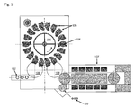
- FIG. 1 shows a schematic plan view of an exemplary embodiment of an apparatus for producing and filling plastic containers according to the present invention.
- the apparatus is formed in this exemplary embodiment with a rotary 104, along the circumference of a plurality of treatment stations 105 circulate in the form of the Gremanmaschinen described below.
- Each of the circulating treatment stations comprises a hollow mold 106 for shaping and filling the plastic containers.
- a plurality of forming and filling stations is provided, which are arranged in particular on the outer circumference of a continuously rotating rotary traveler.
- the rotary machine is preferably a wheel.
- the rotator rotates in particular about a vertical axis whose extension cuts the center of the earth.
- the stations are all arranged at equidistant intervals from each other.
- the stations have cavities within which the containers are expanded against the inner walls of the cavity so that the finished containers receive the (negative) shape of the inner walls of the cavity.
- the preforms 103 schematically shown here pass through an oven 107, for example an infrared oven or a microwave oven, in which the preforms 103 are heated with a desired temperature profile along their longitudinal axis. While the microwave oven is preferably a rotary machine, the preforms in the infrared oven are transported in a straight line at least part of the distance.
- the heated preforms 103 are then transferred via an inlet star 108 to the rotor 104 and in particular introduced into the open molds 106.
- the preforms are formed and filled within the now closed hollow molds 106 of the treatment stations 105. Before transfer to an outlet star 109, the molds are opened again to remove the now fully formed and filled plastic containers.
- the temperature profile applied in the oven 107 can be predetermined depending on the desired shape of the plastic container and its material. Furnaces for preheating preforms are well known in the art and therefore will not be further described here. From the outlet star 109, the finished and filled containers 102 can be transferred to a conveyor belt for further treatment. It is understood that other treatment stations, such as sealing units and / or labeling stations, can be provided in the periphery of the rotary machine 104 or as part of the mold filling machines 105. The following descriptions are limited to the process of forming and filling the plastic containers for the sake of clarity of understanding only. In particular, it is thought to close the container still within this cavity. For this purpose, a shutter feed can be arranged on the periphery of the rotary.
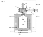
- FIG. 2 shows a side view of an exemplary embodiment of a mold filling machine according to the present invention.
- the mold filling machine comprises a mold which is designed as a hollow mold, wherein the mold in the non-limiting embodiment shown here consists of two side parts 106a and 106b which can be moved or swiveled in the direction of the arrows by means of a multipart mold carrier 110 and a bottom part 106c which can be moved along the direction of the arrow.
- the mold is closed by moving the mold parts 106a-c together.
- the mold can be formed such that it terminates pressure-tight with the preform 103 and thus forms a pressure-tight mold 106, by means of a media distributor 119, for example, a common rotary distributor for the plurality of treatment stations, via suction lines 118 for the mold to support the molding process can be evacuated to negative pressure.
- a media distributor 119 for example, a common rotary distributor for the plurality of treatment stations
- a fluid nozzle of a valve block 111 can be placed pressure-tight on the mouth region 121 of the preform, according to the known in the prior art, via which the above-described media and / or filling products in the preform or the Schwarzformenden plastic container with each desired pressure can be injected or -blown.
- the valve block 111 is connected to the media distributor 119 via a feed line for a shaping fluid 114 and / or a feed line for a filling product 115.
- Controllable valves in the valve block 111 regulate the supply of molding fluid and / or filling product.
- the molding fluid may be a gaseous medium which is compressed, for example with a compressor 120, to the pressure required to form the preform.
- the molding fluid may also be a filling product or the filling product at a first temperature.
- a suitable overpressure in the fluid can be generated. The same applies to the filling product in the supply line 115, wherein according to a development, the remaining molding of the container with this filling product can be made.
- the non-limiting form-filling machine shown here can furthermore have a stretching rod 113, which can be moved into the preform along the arrow direction shown, in order to stretch the preform to its desired length, which corresponds to the height of the finished plastic container.
- a stretching rod 113 When using a hollow-bored stretching rod 113, medium or filling product which has already been filled, for example, already shown as an extraction line 116 as an example, can again escape from the container or be actively withdrawn.
- the stretch rod 113 can be used for filling and / or further molding of the container.
- the stretch rod 113 may have an opening and / or openings arranged along its longitudinal direction at its end facing the mold. The latter can be used in particular for the effective mixing of hot and cold filling product according to the development described above.
- FIG. 2 shown arrangement, in particular the supply lines or suction lines 114 to 117, merely represents an exemplary development. A variety of alternative developments is conceivable, of which some are described explicitly below.
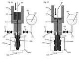
- FIG. 3 schematically shows a valve assembly for molding a container in two steps.
- the valve block comprises a first supply line 314 for supplying a medium to the filling nozzle (not shown) in the connection area 112 of the FIG Valve head, and thus in the preform 303, for partially molding the preform 303 and a second feed line 315 for supplying the filling product in the solicitformenden container 302.
- Both the medium and the filling product are filled under pressure in the preform or the container to to stretch the walls of the container to be formed outwardly towards the inner wall of the mold (not shown).
- a first part of this molding operation is carried out by opening the valve 324 in the first supply line 314, while the remaining molding of the container to its final shape by opening the valve 325 in the second supply line 315.
- the two phases of the molding are shown in the figure with reference to the arrows on the left or right side of the figure.
- the first step of molding shown on the left thus corresponds to a "pre-blowing" of the preform onto an intermediate mold which, for example, has at least 50%, preferably at least 80%, of the final longitudinal stretch of the preform.
- the "pre-blowing" can be supported by a stretch rod, not shown here.
- the first step can be carried out with a compressed gas, for example an inert gas or CO 2 , as the medium, so that premature cooling of the plastic to be stretched below its crystallization temperature can be prevented.
- a compressed gas for example an inert gas or CO 2
- both the rest of the molding and the cooling of the container can be carried out.
- this method is particularly suitable for carbonated drinks, which should be filled as cold as possible in order to avoid the decontamination of the dissolved carbonic acid.
- a special blowing nozzle may be used with a valve which is opened to escape the gas. Since the container is only partially formed with compressed gas, the energy required for providing the gas decreases.
- relatively cool fill product can "blown" so that the heat requirement is lower compared to complete hot fill product molding (see below).
- the medium is the filling product with a first, relatively high temperature, which can be selected accordingly, in order to avoid the crystallization of the plastic during stretching.
- another filling product can be filled with this first temperature, especially if it is mixed drinks. Since only the first part of the shaping takes place with the hot filling product as the medium, the mixing temperature after filling of the cold filling product by the second supply line 315 relative to the exclusive molds with hot filling product can be reduced, so that a subsequent cooling device can be designed with lower performance or eliminated.
- both variants can be dispensed by filling the filling product with low temperature to the remaining molding on a separate cooling for the mold, since the container is already cooled by the filled product.
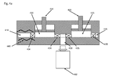
- FIGS. 4a-c show various embodiments of the valve block for forming a container in two steps, in particular for the "pre-blowing" with hot filling product and "pre-blowing” with cold filling product.
- FIG. 4a shows a first variant in which the first supply line 414 and the second supply line 415 each have their own pressure chamber 444 and 445 respectively.
- the pressure chambers illustrated here represent a possibility of building up a desired pressure in a fluid introduced into the container 402, in particular the substantially liquid filling product, by moving a corresponding reciprocating piston 454 or 455.
- the respective downstream valve 424 or 425 is first closed to fill the respective pressure chamber by opening the respective upstream valve 434 or 435 to a predetermined level.
- the level is set by the end position of the reciprocating piston 454 and 455 when filling the pressure chamber, so that with a single pressure chamber different dosing volumes can be adjusted.
- the reciprocating piston can be moved accordingly by means of a control and / or regulating device and a servo motor. After filling the pressure chamber, the respective inlet valve 434 or 435 is closed and the respective outlet valve 424 or 425 is opened. By lowering the reciprocating piston, the pressure chamber is then emptied through the common filling channel 430 into the container 402. Since the mouth region of the container is pressure-tightly connected to the filling channel 430, the container or the preform can be stretched and formed by the built-up pressure.
- the control and / or regulating device controls the opening and closing of the valves and the movement of the reciprocating piston. Normally, only one of the intake valves is always 424 and 425 open. However, in mixed drinks, both inlet valves may be simultaneously opened to fill various fill products through the inlet channel 430 into the container.
- the figure also shows a heating device 440 in the form of a continuous flow heater for heating the filling product conveyed by the supply line 414 to the first temperature described above.
- a heating device 440 in the form of a continuous flow heater for heating the filling product conveyed by the supply line 414 to the first temperature described above.
- This can be chosen as described so that the plastic can be stretched without crystallization.
- the heating device 440 may also be mounted elsewhere, for example on the pressure chamber 444.
- the second supply line 415 may also have an independent heating device in order to be able to set the temperature of the filling product in the second supply line in a targeted manner.
- the heating devices can be designed to be controllable and controlled or regulated by the control and / or regulating device.
- FIG. 4b shows an alternative variant to the in FIG. 4a illustrated training.
- a common pressure chamber 446 with reciprocating piston 456 is provided for the medium supplied from the first supply line 414 and the filling product supplied from the second supply line 415.
- the supply of the medium or of the filling product is regulated via the inlet valves 434 or 435 as before. Since only one pressure chamber is provided, only one outlet valve 426 is required for the filling channel 430.
- the regulation of the valves and the reciprocating piston corresponds to the development of FIG. 4a and therefore will not be described repeatedly here. Also in this development, mixing of filling products, in this case in the pressure chamber 446, is possible.
- the first supply line has a heater 440. Corresponding developments as in FIG. 4a are also conceivable here.
- FIGS. 4a and 4b differs from the developments of FIGS. 4a and 4b inasmuch as now a single supply line 450 is provided for a single filling product. Accordingly, again only one pressure chamber 446 is provided with reciprocating piston 456, whose inlet and outlet are controlled by controllable valves 436 and 426.
- a heating device 441 is now provided, which is only activated by the control and / or regulating device when, for "pre-blowing" with hot filling product, the filling product pressed through the channel is to be heated to the first temperature.
- the heating device can also be arranged on the pressure chamber 446, for example to heat only the first batch of the filling product for "pre-blowing" the container 402 to the first temperature. The rest of the molding of the container then takes place with deactivated heater and filling product with the second, lower temperature.
- the first temperature of the "pre-bubble" filling product can be adjusted by controlling the heating power of the heating device as a function of the temperature of the preform as it exits the oven.
- the temperature of the preform can be measured with a temperature probe, for example in the form of a pyrometer, at the outlet of the furnace.
- the first temperature can be chosen in particular such that it is equal to the average surface temperature of the preform. This does not overly affect the preform temperature profile previously applied in the oven, while the plastic can still be "quenched” by the second step of filling a cold fill product, as in the normal blow process by contact with the blow mold wall.
- the method is particularly advantageous for CO 2 -containing beverages, which are preferably filled cold, in order to obtain a good solubility of CO 2 in the product.
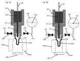
- the Figures 5a-k 10 show snapshots of a method for mold-filling a container, in which the liquid used for molding with the first (hotter) temperature is for the most part withdrawn from the molded container.
- the mold filling machine has a pressure chamber 547, which can be acted upon by moving a reciprocating piston 554 with pressure.
- the reciprocating piston 554 can be pulled out of the pressure chamber, for example, by means of a servomotor and pushed back into it, so that a liquid 544 can be sucked through the feed line 514 into the pressure chamber 547 and pressed out of it.
- the liquid 544 may in particular be the filling product, which is heated to the first temperature with a heating device (not shown) on the pressure chamber 547 or the supply line 514.
- a heating device not shown
- the liquid heated to the first temperature is used to fully mold the preform 502 to the final shape.
- the liquid used for this purpose is almost completely removed again from the finished molded container and stored to form the next container in the pressure chamber 547.
- the supply line 514 simultaneously acts as a suction line for withdrawing the liquid from the finished molded container. In this case, mixing of the liquid 544 with the liquid which does not replace the withdrawn liquid 575 at a lower temperature is not completely avoided can be heated, the liquid 544 after retraction again to the first temperature.
- the feed or suction line 514 opens into the linearly movable and hollow-bored stretch rod 513.
- the stretch rod 513 is shown in the fully retracted home position.
- the stretch rod 513 can be moved relative to the valve head (below the pressure chamber 547).
- a second feed line 515 for the cool filling product 575 at the second temperature and an outlet line 527 for the escape of gas from the preform or container 502 are guided into the mouth region 532 of the preform by the valve head.
- the lower part of the valve head placed on the mouth region may in this case comprise corresponding filling nozzles (not shown here).
- the supply line 515 connects in the exemplary embodiment shown here a reservoir 565 for the cool filling product 575 with the valve head.
- the supply of the filling product 575 with the second temperature is controlled via a controllable valve 525. Further provided in the outlet 527 with a controllable valve 528 to build pressure in the preform with the valve closed.
- FIG. 5a shows the mold filling machine with open mold 506a-c, in which however already a preform 502a has been introduced.
- the valves 525 and 528 are closed and the reciprocating piston 554 is in the maximum retracted position so that the entire amount of liquid 544 for forming the container is in the pressure chamber 547.
- the stretch rod 513 is in the maximum retracted position.
- FIG. 5b the mold was closed by moving the mold parts 506a-c together and the mouth region 532 of the preform 502b pressed against a closing ring of the valve head so that the mold forms a pressure-tight closed cavity and the mouth of the preform 502b is pressure-tight with the valve head.
- Material exchange, whether gaseous or liquid, with the interior of the preform thus takes place exclusively via the illustrated lines 514, 515 and 527.
- FIG. 5c shows a phase in which the preform 502c has been stretched by extending the stretch rod 513 to the bottom mold 506c, but has not yet been filled with the liquid 544.
- the displaced by the liquid 544 from the preform 502 d gas can escape by opening the valve 528 through the outlet 527. It is understood that the filling of the liquid 544 may also begin during the stretching of the preform 502c.
- the valve 528 is closed again to build up a To allow pressure in the preform. This is done by further lowering the reciprocating piston 554 in the pressure chamber 547.
- the preform 502e expands until it as in FIG. 5f shown reached the final shape of the plastic container.
- the now fully formed container 502f bears against the inner wall of the mold 506a-c and is completely filled with the liquid 544.
- the filled liquid 544 has a relatively high temperature corresponding to the temperature of the preform, whitening or haze of PET material during molding may be avoided.
- FIG. 5g shows a moment in which already a part of the liquid 544 has been replaced by the filling product 575.
- the thermal buoyancy Due to the thermal buoyancy, this allows a rapid mixing of a residue of the hot liquid remaining at the bottom of the container 502h with the filled cold filling product, so that the inner wall of the container can be cooled uniformly and rapidly.
- the filling product 575 may additionally be pressurized within the reservoir 565.
- the mold parts 506a-c are moved apart to remove the completely formed and filled container 502k. This completes the cycle and can begin again with another preform.
- a closer can also be provided as part of the mold filling machine be used to close the filled containers under pressure. This can prevent the release of CO 2 from carbonated drinks.
- plastic containers can be formed hot and cooled quickly, so that stress whitening and turbidity in the material can be avoided.
- the heat energy of the molding liquid can be largely preserved for the next molding process.
- the solidified container wall is thus dimensionally stable already upon removal of the container from the mold filling machine and can be easily transported and treated. Since it is filled with cold product, the method is particularly suitable for carbonated and heat-sensitive drinks.
Priority Applications (1)
| Application Number | Priority Date | Filing Date | Title |
|---|---|---|---|
| EP14181660.3A EP2987619A1 (fr) | 2014-08-20 | 2014-08-20 | Remplisseuse de moule et procédé de démoulage et de remplissage de récipients |
Applications Claiming Priority (1)
| Application Number | Priority Date | Filing Date | Title |
|---|---|---|---|
| EP14181660.3A EP2987619A1 (fr) | 2014-08-20 | 2014-08-20 | Remplisseuse de moule et procédé de démoulage et de remplissage de récipients |
Publications (1)
| Publication Number | Publication Date |
|---|---|
| EP2987619A1 true EP2987619A1 (fr) | 2016-02-24 |
Family
ID=51389989
Family Applications (1)
| Application Number | Title | Priority Date | Filing Date |
|---|---|---|---|
| EP14181660.3A Withdrawn EP2987619A1 (fr) | 2014-08-20 | 2014-08-20 | Remplisseuse de moule et procédé de démoulage et de remplissage de récipients |
Country Status (1)
| Country | Link |
|---|---|
| EP (1) | EP2987619A1 (fr) |
Cited By (4)
| Publication number | Priority date | Publication date | Assignee | Title |
|---|---|---|---|---|
| CN109863012A (zh) * | 2016-10-28 | 2019-06-07 | 株式会社吉野工业所 | 液体吹塑成型方法 |
| EP3536479A1 (fr) * | 2018-03-07 | 2019-09-11 | Krones AG | Dispositif et procédé d'expansion et de remplissage simultané de récipients |
| EP3536480A1 (fr) * | 2018-03-07 | 2019-09-11 | Krones AG | Dispositif et procédé d'expansion et de remplissage simultané de récipients |
| EP3542986A1 (fr) * | 2018-03-23 | 2019-09-25 | Krones AG | Dispositif de formage et de remplissage de récipients en matière plastique à remplissage commandé |
Citations (3)
| Publication number | Priority date | Publication date | Assignee | Title |
|---|---|---|---|---|
| EP1529620B1 (fr) | 2003-11-06 | 2009-02-25 | Nestlé Waters Management & Technology | Procédé de fabrication de contenants en résine polyester |
| US20110031659A1 (en) | 2005-03-15 | 2011-02-10 | Graeme Warner | Stretch Blow Moulding Method and Apparatus |
| DE102011011076A1 (de) * | 2011-02-11 | 2012-08-16 | Khs Gmbh | Verfahren sowie Vorrichtung zum Herstellen von mit einem flüssigen Füllgut gefüllten Behältern |
-
2014
- 2014-08-20 EP EP14181660.3A patent/EP2987619A1/fr not_active Withdrawn
Patent Citations (3)
| Publication number | Priority date | Publication date | Assignee | Title |
|---|---|---|---|---|
| EP1529620B1 (fr) | 2003-11-06 | 2009-02-25 | Nestlé Waters Management & Technology | Procédé de fabrication de contenants en résine polyester |
| US20110031659A1 (en) | 2005-03-15 | 2011-02-10 | Graeme Warner | Stretch Blow Moulding Method and Apparatus |
| DE102011011076A1 (de) * | 2011-02-11 | 2012-08-16 | Khs Gmbh | Verfahren sowie Vorrichtung zum Herstellen von mit einem flüssigen Füllgut gefüllten Behältern |
Cited By (10)
| Publication number | Priority date | Publication date | Assignee | Title |
|---|---|---|---|---|
| CN109863012A (zh) * | 2016-10-28 | 2019-06-07 | 株式会社吉野工业所 | 液体吹塑成型方法 |
| EP3533584A4 (fr) * | 2016-10-28 | 2020-06-10 | Yoshino Kogyosho Co., Ltd. | Procédé de moulage par soufflage de liquide |
| US10940631B2 (en) | 2016-10-28 | 2021-03-09 | Yoshino Kogyosho Co., Ltd. | Liquid blow molding method |
| CN109863012B (zh) * | 2016-10-28 | 2021-03-12 | 株式会社吉野工业所 | 液体吹塑成型方法 |
| EP3536479A1 (fr) * | 2018-03-07 | 2019-09-11 | Krones AG | Dispositif et procédé d'expansion et de remplissage simultané de récipients |
| EP3536480A1 (fr) * | 2018-03-07 | 2019-09-11 | Krones AG | Dispositif et procédé d'expansion et de remplissage simultané de récipients |
| EP3542986A1 (fr) * | 2018-03-23 | 2019-09-25 | Krones AG | Dispositif de formage et de remplissage de récipients en matière plastique à remplissage commandé |
| CN110293669A (zh) * | 2018-03-23 | 2019-10-01 | 克朗斯股份有限公司 | 采用受控灌装变形和灌装塑料容器的设备 |
| CN110293669B (zh) * | 2018-03-23 | 2021-10-22 | 克朗斯股份有限公司 | 采用受控灌装变形和灌装塑料容器的设备 |
| US11426920B2 (en) | 2018-03-23 | 2022-08-30 | Krones Ag | Apparatus for transforming and filling plastics material containers with controlled filling |
Similar Documents
| Publication | Publication Date | Title |
|---|---|---|
| DE60015577T2 (de) | Blasformverfahren und blasformvorrichtung zum herstellen von pasteurisierbaren behältern | |
| EP2516133B1 (fr) | Procede et dispositif de fabrication de recipients remplis | |
| EP2670668B1 (fr) | Procédé et dispositif de fabrication de récipients remplis avec un produit liquide | |
| DE60314627T2 (de) | Verfahren zur herstellung eines behälters aus polyesterharz und vorrichtung zur durchführung desselben | |
| EP2269803B1 (fr) | Procédé de changement d'outillage d'une souffleuse et souffleuse | |
| EP2879960B1 (fr) | Procédé et dispositif de fabrication de contenants remplis d'un produit liquide | |
| EP2930138A1 (fr) | Dispositif et procédé de fabrication d'une bouteille en plastique et de son remplissage d'un produit de remplissage | |
| EP2522482B1 (fr) | Procédé et dispositif de fabrication de préformes avec géométrie spéciale | |
| EP2522485B1 (fr) | Machine et procédé de formage par soufflage aseptique avec évacuation stérile de l'air, ainsi que moule de soufflage | |
| DE102011012751B4 (de) | Verfahren sowie Anlage zu Herstellung von mit einem flüssigen Füllgut gefüllten Behältern | |
| EP2987607B1 (fr) | Procédé de moulage et remplissage | |
| EP2987619A1 (fr) | Remplisseuse de moule et procédé de démoulage et de remplissage de récipients | |
| DE102011011076A1 (de) | Verfahren sowie Vorrichtung zum Herstellen von mit einem flüssigen Füllgut gefüllten Behältern | |
| EP3412429A1 (fr) | Dispositif de formage par soufflage | |
| DE102012015086A1 (de) | Verfahren sowie Vorrichtung zum Herstellen von mit einem flüssigen Füllgut gefüllten Behältern | |
| EP2987606A1 (fr) | Procédé de démoulage et de remplissage de récipient et remplisseuse de moule | |
| EP2987610B1 (fr) | Remplisseuse de moule destinée à fabriquer et à remplir des récipients en plastique par recyclage de CO2 | |
| DE102011012664A1 (de) | Verfahren und Vorrichtung zur Herstellung von mit einem flüssigen Füllgut gefüllten Behältern | |
| DE102013103543A1 (de) | Vorrichtung und Verfahren zum Umformen von Kunststoffvorformlingen zu Kunststoffbehältnissen | |
| EP2352632A2 (fr) | Dispositif et procédé de fabrication de contenants en plastique et contenant en plastique fabriqué par ce procédé | |
| EP3784469B1 (fr) | Voies d'air de soufflage stérilisables et poinçon d'étirage d'une machine de soufflage | |
| EP2735428A1 (fr) | Procédé d'étirage-soufflage et machine d'étirage-soufflage | |
| DE102015120768A1 (de) | Verfahren zum Befüllen von durch Streckblasen hergestellten Kunststoffbehältern | |
| EP2987620A1 (fr) | Remplisseuse de moule destinée à démouler et à remplir des récipients | |
| EP2987617B1 (fr) | Bloc de soupapes pour une station de traitement d'une machine de souflage et remplissage et machine de souflage et remplissage dotée d'un bloc de soupapes |
Legal Events
| Date | Code | Title | Description |
|---|---|---|---|
| PUAI | Public reference made under article 153(3) epc to a published international application that has entered the european phase |
Free format text: ORIGINAL CODE: 0009012 |
|
| 17P | Request for examination filed |
Effective date: 20151207 |
|
| AK | Designated contracting states |
Kind code of ref document: A1 Designated state(s): AL AT BE BG CH CY CZ DE DK EE ES FI FR GB GR HR HU IE IS IT LI LT LU LV MC MK MT NL NO PL PT RO RS SE SI SK SM TR |
|
| AX | Request for extension of the european patent |
Extension state: BA ME |
|
| 17Q | First examination report despatched |
Effective date: 20170105 |
|
| STAA | Information on the status of an ep patent application or granted ep patent |
Free format text: STATUS: THE APPLICATION IS DEEMED TO BE WITHDRAWN |
|
| 18D | Application deemed to be withdrawn |
Effective date: 20190904 |