EP2522482B1 - Procédé et dispositif de fabrication de préformes avec géométrie spéciale - Google Patents
Procédé et dispositif de fabrication de préformes avec géométrie spéciale Download PDFInfo
- Publication number
- EP2522482B1 EP2522482B1 EP12178952.3A EP12178952A EP2522482B1 EP 2522482 B1 EP2522482 B1 EP 2522482B1 EP 12178952 A EP12178952 A EP 12178952A EP 2522482 B1 EP2522482 B1 EP 2522482B1
- Authority
- EP
- European Patent Office
- Prior art keywords
- preform
- removal
- preforms
- gripper
- injection mould
- Prior art date
- Legal status (The legal status is an assumption and is not a legal conclusion. Google has not performed a legal analysis and makes no representation as to the accuracy of the status listed.)
- Active
Links
Images


Classifications
-
- B—PERFORMING OPERATIONS; TRANSPORTING
- B29—WORKING OF PLASTICS; WORKING OF SUBSTANCES IN A PLASTIC STATE IN GENERAL
- B29B—PREPARATION OR PRETREATMENT OF THE MATERIAL TO BE SHAPED; MAKING GRANULES OR PREFORMS; RECOVERY OF PLASTICS OR OTHER CONSTITUENTS OF WASTE MATERIAL CONTAINING PLASTICS
- B29B11/00—Making preforms
- B29B11/06—Making preforms by moulding the material
- B29B11/08—Injection moulding
-
- B—PERFORMING OPERATIONS; TRANSPORTING
- B29—WORKING OF PLASTICS; WORKING OF SUBSTANCES IN A PLASTIC STATE IN GENERAL
- B29C—SHAPING OR JOINING OF PLASTICS; SHAPING OF MATERIAL IN A PLASTIC STATE, NOT OTHERWISE PROVIDED FOR; AFTER-TREATMENT OF THE SHAPED PRODUCTS, e.g. REPAIRING
- B29C45/00—Injection moulding, i.e. forcing the required volume of moulding material through a nozzle into a closed mould; Apparatus therefor
- B29C45/17—Component parts, details or accessories; Auxiliary operations
- B29C45/26—Moulds
- B29C45/261—Moulds having tubular mould cavities
-
- B—PERFORMING OPERATIONS; TRANSPORTING
- B29—WORKING OF PLASTICS; WORKING OF SUBSTANCES IN A PLASTIC STATE IN GENERAL
- B29C—SHAPING OR JOINING OF PLASTICS; SHAPING OF MATERIAL IN A PLASTIC STATE, NOT OTHERWISE PROVIDED FOR; AFTER-TREATMENT OF THE SHAPED PRODUCTS, e.g. REPAIRING
- B29C45/00—Injection moulding, i.e. forcing the required volume of moulding material through a nozzle into a closed mould; Apparatus therefor
- B29C45/17—Component parts, details or accessories; Auxiliary operations
- B29C45/40—Removing or ejecting moulded articles
- B29C45/42—Removing or ejecting moulded articles using means movable from outside the mould between mould parts, e.g. robots
- B29C45/4225—Take-off members or carriers for the moulded articles, e.g. grippers
-
- B—PERFORMING OPERATIONS; TRANSPORTING
- B29—WORKING OF PLASTICS; WORKING OF SUBSTANCES IN A PLASTIC STATE IN GENERAL
- B29C—SHAPING OR JOINING OF PLASTICS; SHAPING OF MATERIAL IN A PLASTIC STATE, NOT OTHERWISE PROVIDED FOR; AFTER-TREATMENT OF THE SHAPED PRODUCTS, e.g. REPAIRING
- B29C45/00—Injection moulding, i.e. forcing the required volume of moulding material through a nozzle into a closed mould; Apparatus therefor
- B29C45/17—Component parts, details or accessories; Auxiliary operations
- B29C45/72—Heating or cooling
- B29C45/7207—Heating or cooling of the moulded articles
-
- B—PERFORMING OPERATIONS; TRANSPORTING
- B29—WORKING OF PLASTICS; WORKING OF SUBSTANCES IN A PLASTIC STATE IN GENERAL
- B29C—SHAPING OR JOINING OF PLASTICS; SHAPING OF MATERIAL IN A PLASTIC STATE, NOT OTHERWISE PROVIDED FOR; AFTER-TREATMENT OF THE SHAPED PRODUCTS, e.g. REPAIRING
- B29C49/00—Blow-moulding, i.e. blowing a preform or parison to a desired shape within a mould; Apparatus therefor
- B29C49/02—Combined blow-moulding and manufacture of the preform or the parison
- B29C49/06—Injection blow-moulding
-
- B—PERFORMING OPERATIONS; TRANSPORTING
- B29—WORKING OF PLASTICS; WORKING OF SUBSTANCES IN A PLASTIC STATE IN GENERAL
- B29C—SHAPING OR JOINING OF PLASTICS; SHAPING OF MATERIAL IN A PLASTIC STATE, NOT OTHERWISE PROVIDED FOR; AFTER-TREATMENT OF THE SHAPED PRODUCTS, e.g. REPAIRING
- B29C49/00—Blow-moulding, i.e. blowing a preform or parison to a desired shape within a mould; Apparatus therefor
- B29C49/18—Blow-moulding, i.e. blowing a preform or parison to a desired shape within a mould; Apparatus therefor using several blowing steps
-
- B—PERFORMING OPERATIONS; TRANSPORTING
- B29—WORKING OF PLASTICS; WORKING OF SUBSTANCES IN A PLASTIC STATE IN GENERAL
- B29C—SHAPING OR JOINING OF PLASTICS; SHAPING OF MATERIAL IN A PLASTIC STATE, NOT OTHERWISE PROVIDED FOR; AFTER-TREATMENT OF THE SHAPED PRODUCTS, e.g. REPAIRING
- B29C49/00—Blow-moulding, i.e. blowing a preform or parison to a desired shape within a mould; Apparatus therefor
- B29C49/42—Component parts, details or accessories; Auxiliary operations
- B29C49/4205—Handling means, e.g. transfer, loading or discharging means
-
- B—PERFORMING OPERATIONS; TRANSPORTING
- B29—WORKING OF PLASTICS; WORKING OF SUBSTANCES IN A PLASTIC STATE IN GENERAL
- B29C—SHAPING OR JOINING OF PLASTICS; SHAPING OF MATERIAL IN A PLASTIC STATE, NOT OTHERWISE PROVIDED FOR; AFTER-TREATMENT OF THE SHAPED PRODUCTS, e.g. REPAIRING
- B29C49/00—Blow-moulding, i.e. blowing a preform or parison to a desired shape within a mould; Apparatus therefor
- B29C49/42—Component parts, details or accessories; Auxiliary operations
- B29C49/48—Moulds
-
- B—PERFORMING OPERATIONS; TRANSPORTING
- B29—WORKING OF PLASTICS; WORKING OF SUBSTANCES IN A PLASTIC STATE IN GENERAL
- B29C—SHAPING OR JOINING OF PLASTICS; SHAPING OF MATERIAL IN A PLASTIC STATE, NOT OTHERWISE PROVIDED FOR; AFTER-TREATMENT OF THE SHAPED PRODUCTS, e.g. REPAIRING
- B29C45/00—Injection moulding, i.e. forcing the required volume of moulding material through a nozzle into a closed mould; Apparatus therefor
- B29C45/17—Component parts, details or accessories; Auxiliary operations
- B29C45/72—Heating or cooling
- B29C45/7207—Heating or cooling of the moulded articles
- B29C2045/7214—Preform carriers for cooling preforms
-
- B—PERFORMING OPERATIONS; TRANSPORTING
- B29—WORKING OF PLASTICS; WORKING OF SUBSTANCES IN A PLASTIC STATE IN GENERAL
- B29C—SHAPING OR JOINING OF PLASTICS; SHAPING OF MATERIAL IN A PLASTIC STATE, NOT OTHERWISE PROVIDED FOR; AFTER-TREATMENT OF THE SHAPED PRODUCTS, e.g. REPAIRING
- B29C49/00—Blow-moulding, i.e. blowing a preform or parison to a desired shape within a mould; Apparatus therefor
- B29C49/02—Combined blow-moulding and manufacture of the preform or the parison
- B29C2049/023—Combined blow-moulding and manufacture of the preform or the parison using inherent heat of the preform, i.e. 1 step blow moulding
-
- B—PERFORMING OPERATIONS; TRANSPORTING
- B29—WORKING OF PLASTICS; WORKING OF SUBSTANCES IN A PLASTIC STATE IN GENERAL
- B29C—SHAPING OR JOINING OF PLASTICS; SHAPING OF MATERIAL IN A PLASTIC STATE, NOT OTHERWISE PROVIDED FOR; AFTER-TREATMENT OF THE SHAPED PRODUCTS, e.g. REPAIRING
- B29C49/00—Blow-moulding, i.e. blowing a preform or parison to a desired shape within a mould; Apparatus therefor
- B29C49/42—Component parts, details or accessories; Auxiliary operations
- B29C49/4205—Handling means, e.g. transfer, loading or discharging means
- B29C49/42073—Grippers
- B29C49/42087—Grippers holding outside the neck
-
- B—PERFORMING OPERATIONS; TRANSPORTING
- B29—WORKING OF PLASTICS; WORKING OF SUBSTANCES IN A PLASTIC STATE IN GENERAL
- B29C—SHAPING OR JOINING OF PLASTICS; SHAPING OF MATERIAL IN A PLASTIC STATE, NOT OTHERWISE PROVIDED FOR; AFTER-TREATMENT OF THE SHAPED PRODUCTS, e.g. REPAIRING
- B29C49/00—Blow-moulding, i.e. blowing a preform or parison to a desired shape within a mould; Apparatus therefor
- B29C49/42—Component parts, details or accessories; Auxiliary operations
- B29C49/4242—Means for deforming the parison prior to the blowing operation
- B29C49/42421—Means for deforming the parison prior to the blowing operation before laying into the mould
-
- B—PERFORMING OPERATIONS; TRANSPORTING
- B29—WORKING OF PLASTICS; WORKING OF SUBSTANCES IN A PLASTIC STATE IN GENERAL
- B29C—SHAPING OR JOINING OF PLASTICS; SHAPING OF MATERIAL IN A PLASTIC STATE, NOT OTHERWISE PROVIDED FOR; AFTER-TREATMENT OF THE SHAPED PRODUCTS, e.g. REPAIRING
- B29C49/00—Blow-moulding, i.e. blowing a preform or parison to a desired shape within a mould; Apparatus therefor
- B29C49/42—Component parts, details or accessories; Auxiliary operations
- B29C49/64—Heating or cooling preforms, parisons or blown articles
- B29C49/6409—Thermal conditioning of preforms
- B29C49/6427—Cooling of preforms
-
- B—PERFORMING OPERATIONS; TRANSPORTING
- B29—WORKING OF PLASTICS; WORKING OF SUBSTANCES IN A PLASTIC STATE IN GENERAL
- B29K—INDEXING SCHEME ASSOCIATED WITH SUBCLASSES B29B, B29C OR B29D, RELATING TO MOULDING MATERIALS OR TO MATERIALS FOR MOULDS, REINFORCEMENTS, FILLERS OR PREFORMED PARTS, e.g. INSERTS
- B29K2105/00—Condition, form or state of moulded material or of the material to be shaped
- B29K2105/25—Solid
- B29K2105/253—Preform
- B29K2105/258—Tubular
-
- B—PERFORMING OPERATIONS; TRANSPORTING
- B29—WORKING OF PLASTICS; WORKING OF SUBSTANCES IN A PLASTIC STATE IN GENERAL
- B29L—INDEXING SCHEME ASSOCIATED WITH SUBCLASS B29C, RELATING TO PARTICULAR ARTICLES
- B29L2031/00—Other particular articles
- B29L2031/712—Containers; Packaging elements or accessories, Packages
- B29L2031/7158—Bottles
Definitions
- the present invention relates to a method and an apparatus for producing preforms according to the preamble of claims 1 and 9, respectively.
- preform or preform In the production of plastic bottles, it is customary first to produce a so-called preform or preform, which is inflated in a subsequent step by a blow molding process to form a finished plastic bottle. Blow molding of prefabricated preforms to finished plastic containers is no longer needed JP 59 002818 A and JP 4 119819 A known.
- a plastic material eg plastic granulate
- Such an injection mold usually has a plurality of identical cavities, which are also referred to as mold cavities.
- the mold cavities in addition to a so-called neck or neck area comprise a Kavticiansaus simplifiedung into which a core protrudes.
- the core defines the interior of the preform, the Kavticiansaus Principleung together with the neck or neck area, the outer contour of the preform - together they define the geometry of the preform.
- a first cooling operation is performed to provide sufficient rigidity for the preforms to obtain, which allows an opening of the injection mold.
- the batch of preforms produced is conventionally removed with a removal gripper from the tool, in which case, in known methods, each preform is transferred into an associated, mostly cooled removal sleeve of a removal gripper.
- the removal sleeves of the removal gripper are usually (water) cooled.
- a method and a device of the aforementioned type are known for example from WO 00/24562 A1 known.
- the company Netstal introduced a method in which the interior of the preforms, which are located in the removal gripper, are pressurized, so that they attach with their outer wall intimately on the wall of the removal gripper and a particularly good cooling as well as a recalibration is ensured.
- the transfer pins of the transfer gripper have means for sealing the interior of the preforms and for introducing a fluid, for example of Air, up.
- a fluid for example of Air
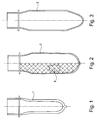
- FIG. Fig. 1 In the process described above, it is common to generate a preform having a design as shown in FIG Fig. 1 is shown.
- the type of design usually results from the fact that when removing the preforms from the injection mold on the one hand, the core must be pulled out of the interior of the preform and on the other hand, the preform itself must be removed from the cavity.
- These two processes would be used in a preform geometry, as in Fig. 2 can not be made directly and without further ado. At least one integrally formed core could not be pulled out of the interior as a rule.
- preforms with a special geometry e.g. can produce an expansion in the bottom region
- the finished preform has a neck region with a thread or other closure device and connects to the neck region a Preform stresses with a relation to the cavity in the injection mold larger or expanded preform body.
- a core idea of the invention is to be seen in that the preforms removed from the tool are initially conditioned in the removal device, ie brought to a certain temperature level, which already significantly reduces the risk of crystallization on the one hand, but enables a further deformation of the preform on the other hand , In contrast to the previous systems may not be for a subsequent blowing process cooled as much as possible to obtain an already solidified as possible preform.
- the transfer pins can be used during the conditioning to seal the interior and put under pressure, so that an optimal contacting of the sleeve wall and thus conditioning and shaping is ensured.
- the present invention it is already possible to carry out a blowing process in the removal gripper itself, and thereby, for example, to blow out the bottom of the preform, in particular in its axial extent.
- the cavity in the removal sleeves of the removal gripper would have to be correspondingly enlarged in the base region.
- the radial outer circumference of the preform would thereby essentially not change, which would not be readily possible, otherwise the preform could not be safely led out of the injection mold.
- Preformböden as for example in the WO 2008/041186 A2 indicated and which are advantageous for later stretch blow molding.
- With a so-called "capello design" preforms can be formed with a thinner preform bottom, with the advantage of saving material and faster cooling. This is particularly interesting when the injection molding production of such contours has disadvantages.
- the preforms After this conditioning, which can be done faster than the previous cooling, especially if only or in the NachksselINA an inflation takes place, because then the preforms need not necessarily be performed at such a low temperature level, the preforms with the transfer gripper from the removal sleeve removed and transferred to the Nachkühl worn.
- the cavities of the aftercooling device (which can also be referred to as a blow molding device) are enlarged relative to the preform produced in the injection mold such that in particular the radial extent of the interior in the inflated preform is greater than the radial extent of the interior in the neck region of the preform.
- an axial expansion can take place. This creates an expanded one Shoulder area, which would represent an undercut in an injection mold and could not be easily removed from the mold.
- a blow-molding process can be carried out either in the extraction sleeve or in the Nachkühl Road or in both devices.
- Such a preform offers a multitude of advantages.
- the preform body increases overall, as a result of which, in a subsequent blow molding step, more infrared light from a blow molding machine can be absorbed, with which the preform for blow molding is reheated.
- the wall thickness decreases, as in the Figures 1 - 3 is recognizable.
- the preform originally produced has a thicker wall thickness 1, whereas the undercut preform geometries have thinner wall thicknesses 2 and 3. This allows the preform to be brought much faster and more accurately to the optimum stretch blow temperature than has hitherto been possible. Again, can be expected with additional energy savings and lower investment costs in the blow molding machine. In addition, you can save depending on the preform geometry possibly plastic material.
- the preform in the post-cooling device with a surface structure, whereby the total surface of the preform is greatly enlarged on its outer side, so that in turn more energy can be absorbed. This would reinforce the two aforementioned effects again. The surface structure would then lose again during the stretching process of the subsequent blow molding.
- the preform geometry not only offers advantages for the subsequent blow molding process; It also has advantages for the own manufacturing process. Due to the thinner wall of the preforms in the cooled blow-molding or after-cooling devices, the cooling time overall can also be reduced here, which contributes to shorter cycle times. This advantageously also means that the risk of crystallization compared to preforms with thick wall thicknesses significantly reduced. Also, due to the conditioning instead of the previous strong cooling reduce the residence time in the removal gripper.
- the after-cooling device acting as a blow-molding device should preferably be water-cooled.
- the cycle time as well as the risk of crystallization of the preforms are reduced.
- the preform should preferably be conditioned to a temperature that is favorable for a subsequent blow molding process.
- a temperature range is for example between 90 and 150 ° C. This is of course only necessary if a subsequent blow-molding process takes place. Without such a blow molding process in the Nachkühl Anlagen founded can be cooled again very aggressive.
- the preform is preferably supported from outside at least during the formation of the overpressure in the neck region or at least in parts of the neck region.
- This support device can in the form of a two or more parts open and be formed closable jaw device, which are each arranged in the region of each transfer pin of the transfer gripper.
- the jaw devices are preferably designed such that they can be combined and / or coupled with the after-cooling device serving as a blow molding device in such a way that the inflated preform is fully supported during its blowing step into its neck region.
- the baking devices may also be cooled, in particular water-cooled.
- the conditioning is particularly supported or accelerated, even if during the recording of the preform in a sampling sleeve whose interior is at least temporarily pressurized (even if in the extraction sleeve no blow molding process takes place).
- Such an overpressure can be maintained in the range of 0.5-8 bar.
- the post-cooling devices may also be configured to receive two, three or more times the charge of a preform charge made in the injection molding tool.
- preforms can be produced with an undercut in a fast cycle time, this geometry also having advantages in the subsequent processing in a blow molding machine. This results in multiple increases in efficiency both during the actual production process of the preform and during the subsequent processing step.
- undercut means that a preform in the area of his shoulder radially expands, so that the undercut is formed with respect to Kavticiansform the injection mold.
- FIGS. 2 and 3 Two such undercut geometries are in the FIGS. 2 and 3 shown, where Fig. 3 also shows a change in the ground contour. Not only is the outer dimension or the outer diameter of the preform in Preform stresses greater than in the neck or neck area, but it is especially the radial diameter of the inner diameter in the preform larger than the radial interior in the neck or neck area. This geometry can not be easily made in an injection mold. At least one core would have to be used which could be radially contracted in the area of the preform body.
- the preform is first prepared in a conventional manner in an injection mold and removed after the first cooling and opening of the tool in the usual way with a removal gripper.
- the removal gripper has a plurality of removal sleeves, in which the preform is usually introduced to the neck or neck area.
- Fig. 4 is shown by such a known removal device 10 only a single removal sleeve 12 from a plurality of removal sleeves to show the inclusion of the preform 14 produced in the previous step in the injection mold can.
- the preform 14 produced initially has a conventional shape with a relatively thick wall thickness and is almost completely accommodated in its body region in the sleeve, which (as not shown in detail here) is water-cooled. In this cooling, whether with air or water, does not need to be discussed in detail, since it is also known from the prior art in various embodiments.
- preform is the front end of a transfer pin of a transfer gripper 16, wherein the transfer gripper 16 has a number of removal sleeves 12 corresponding number of transfer pins 18.
- an elastic sealing device is provided, which can be changed (widened) by compression in its radial dimension.
- a shaft (not shown) of the transfer pin is pushed forward to compress the elastic sleeve and push it radially outwards, whereby it attaches to the inner wall of the preform and the interior of the preform seals against the outside and on the other hand holds. This attachment occurs in particular in the area of the neck ring, where a particular stability is given.
- a stretch rod 24 in the dome-shaped, closed portion of the preform From the front end of the transfer pin 18 extends in this embodiment, a stretch rod 24 in the dome-shaped, closed portion of the preform. About this stretch rod 24 can now be supplied under pressure to the interior of the preform air.
- the stretch rod itself may be formed as a kind of punch and deform the bottom portion of the preforms by applying a stamp-like pressure.
- stamp and air pressure - can be combined.
- the preform By building up an overpressure in the range of 0.5-8 bar, the preform is pressed with its outer walls against the inner wall of the removal sleeve 12 acting as a cooling sleeve, so that a particularly good temperature control and recalibration takes place.
- the bottom area can already be blown out in this position as long as no undercuts are created and the preform is held in a secure contour.
- preform contours can be generated with a so-called. Capello design, as in Fig. 8 is shown.
- each transfer pin 18 of the transfer gripper 16 present two-piece jaws 22 are arranged, wherein the two jaw members radially apart and can be moved to each other.
- the necessary for the movement of the jaws facial expressions and device is not shown in the figures.
- the two jaw elements are moved radially outward. If these jaw elements are moved radially inward, they surround the neck or neck region of the preform (or at least parts of it) in a form-fitting manner, as will be described later on with reference to FIG Fig. 5 can still be shown.
- the removal device 10 with the removal sleeves 12 thus serves not only for removing the preforms from the injection mold, but also for preconditioning to a certain temperature, for example 120 °. In this temperature range, the crystallization risk is already significantly reduced, but still maintain a plasticity of the preform, under which the preform can be deformed. Since the conditioning is carried out to a temperature range of for example 120 ° C - and not to a lower temperature -, a shorter residence time than previously possible in the sampling gripper, which can contribute to overall cycle time reduction. This preconditioning also represents a first difference compared to the hitherto known working and process steps of the best possible cooling.
- the preform becomes supported from the outside and can not change in its dimension.
- the jaw assembly may couple with the blow molding apparatus 26 to provide a complete cavity except for the above opening in the jaw assembly.
- the jaws in the present case are water-cooled (not shown) so as to ensure the fastest possible removal of heat from the preform area with thick wall thickness.
- the still warm and deformable preform is inflated by re-introducing air with a corresponding air pressure of 0.5 - 8 bar, so that expands the Preformwandung and applies to the inside of the enlarged trained Nachkühl coupled.
- the result is in Fig. 6 it can also be seen that the preform wall of the preform 28 has now significantly reduced.
- the preform 28 can be quite quickly brought to a desired and acceptable for the subsequent packaging temperature, since now there is a much thinner wall thickness.
- the transfer pin 18 can be pulled out of the preform 28, wherein the preform 28 itself still remains in the Nachkühl Road and is further cooled there. After a sufficient cooling process, the preform 28 can then be moved over a conveyor belt and ejected by a corresponding air pulse via air supply, not shown on a conveyor belt.
- FIG. 2 shown structures in the outer surface of the preform 2 can be introduced in a corresponding design of the cavity walls either in the removal sleeve or in the Nachkühl worn during inflation.
- the pre-blown preforms 28 are now larger in dimension than the original preforms, the same number of preforms 28 can no longer be accommodated in the after-cooling device 25 in the form of a blowing device 26. For this reason, with a corresponding capacity of the machine, it may be necessary to arrange two identical after-cooling devices 25, for example at the top of the machine, and to alternately transfer the preform batches originating from the unloading device into one and the other after-cooling device. This is in Fig. 7 shown schematically, with only a removal sleeve 12 is shown, from where the preform batches are alternately in the blow mold to the right and in the only slightly re-cooling device to the left (only hinted) are pivoted.
- each post-cooling device 25 can accommodate two or more batches of preforms Mold nests must be matched appropriately both in the tool and in the removal gripper and in the transfer gripper.
Landscapes
- Engineering & Computer Science (AREA)
- Mechanical Engineering (AREA)
- Manufacturing & Machinery (AREA)
- Robotics (AREA)
- Physics & Mathematics (AREA)
- Thermal Sciences (AREA)
- Blow-Moulding Or Thermoforming Of Plastics Or The Like (AREA)
- Processing And Handling Of Plastics And Other Materials For Molding In General (AREA)
Claims (15)
- Procédé de fabrication de préformes dans lequel- des préformes (14) sont fabriquées par injection d'une fonte plastique dans un outil de moulage par injection dont les géométries de cavité des moitiés de moule sont ainsi formées de telle sorte que l'extension radiale de l'espace intérieur dans le corps de préforme ainsi fabriqué est inférieure ou égale à l'extension radiale de l'espace intérieur dans le col,- l'outil de moulage par injection est ouvert après une première étape de refroidissement,- et dans lequel les préformes (14) sont prélevées de l'outil ouvert par un grappin de prélèvement (10), dans lequel le grappin de prélèvement (10) présente un nombre de manchons de prélèvement (12) qui sont respectivement conçus pour recevoir des préformes (14) formées dans l'outil de moulage par injection,caractérisé en ce que
les préformes (14) sont soufflées dans le grappin de prélèvement (10) par emploi de surpression par rapport à la cavité se trouvant dans l'outil de moulage par injection et fixées par leur paroi sur les parois d'une cavité agrandie dans le grappin de prélèvement (10), dans lequel des préformes (28) soufflées préalablement sont fabriquées avec une géométrie modifiée et agrandie par rapport à la cavité de l'outil de moulage par injection, dans lequel la préforme (28) terminée présente un col avec filet ou un dispositif de fermeture et un corps de préforme se raccordant sur le col avec une géométrie modifiée et agrandie par rapport à la cavité de l'outil de moulage par injection. - Procédé selon la revendication 1, caractérisé en ce que lors du soufflage dans le grappin de prélèvement (10), le fond des préformes (14) est soufflé, dans lequel la surpression pendant le soufflage est maintenue de préférence entre 0,5 et 8 bar.
- Procédé selon la revendication 2, caractérisé en ce que le périmètre extérieur radial des préformes (14) est maintenu constant.
- Procédé selon l'une des revendications précédentes, caractérisé en ce que le manchon de prélèvement (12) du grappin de prélèvement (10) est équilibré en température.
- Procédé selon la revendication 4, caractérisé en ce que l'équilibre en température dans le grappin de prélèvement (10) sert à conditionner la préforme (14), dans lequel un conditionnement a lieu de préférence dans une plage de températures entre 90°C et 150°C.
- Procédé selon la revendication 4, caractérisé en ce que l'équilibre en température dans le grappin de prélèvement (10) a lieu à la place du conditionnement des préformes (14) pour le refroidissement puissant habituel.
- Procédé selon l'une des revendications 1 à 8, caractérisé en ce que lors de la formation de la surpression pendant la réception de la préforme (14) dans le grappin de prélèvement (10), le col de la préforme (14) est appuyé par l'extérieur, dans lequel de préférence, le manchon de prélèvement (12) du grappin de prélèvement (10) se raccorde directement sur l'appui de la préforme (14) dans le col, de telle sorte que la préforme (14) est appuyée sur tout son pourtour.
- Procédé selon l'une des revendications précédentes, caractérisé en ce qu'un post-refroidissement a lieu après le soufflage.
- Dispositif destiné à exécuter le procédé selon l'une des revendications 1 à 8,- dans lequel un outil de moulage par injection avec un nombre de cavités de moule pour la formation de géométries de préformes est prévu, dans lequel les différentes géométries de cavité de moule sont ainsi formées dans leur cavité que l'extension radiale de l'espace intérieur libre dans le corps de la préforme est inférieur ou égal à l'extension radiale de l'espace intérieur libre dans le col,- un dispositif de plastification et d'injection est prévu pour fondre une matière plastique et l'introduire dans la cavité de l'outil de moulage par injection fermé,- un grappin de prélèvement (10) comprenant un nombre de manchons de prélèvement (12) est prévu, qui sont conçus pour recevoir des préformes (14) formées dans l'outil de moulage par injection,caractérisé en ce que les cavités des manchons de prélèvement (12) du grappin de prélèvement (10) sont agrandies axialement par rapport à la cavité réalisée dans l'outil de moulage par injection.
- Dispositif selon la revendication 9, caractérisé en ce que les cavités dans le grappin de prélèvement (10) sont agrandies dans un fond de la préforme (14) par rapport aux cavités dans l'outil de moulage par injection.
- Dispositif selon la revendication 9 ou 10, caractérisé en ce qu'un grappin de transfert (16) avec des broches de transfert (18) est prévu, qui peuvent être introduites respectivement dans une préforme (14) correspondante, et que les broches de transfert (18) du grappin de transfert (16) présentent un dispositif d'étanchéité pour étanchéifier un espace intérieur de préforme et un dispositif de pulvérisation de fluide pour introduire du fluide dans l'espace intérieur de préforme.
- Dispositif selon l'une des revendications 9 à 11, caractérisé en ce que les manchons de prélèvement (12) sont conçus en pouvant être équilibrés en température.
- Dispositif selon l'une des revendications 9 à 12, caractérisé en ce qu'il est prévu un dispositif de mâchoires comprenant au moins deux mâchoires (22) pour chaque broche de transfert (18) sur le grappin de transfert (16) qui s'ouvrent au moins radialement et pour faire fermer au moins une partie du col de la préforme correspondante.
- Dispositif selon l'une des revendications 9 à 13, caractérisé en ce que les broches de transfert (18) présentent chacune une barre d'étirage (24).
- Dispositif selon l'une des revendications 9 à 14, caractérisé en ce que les parois de cavité des manchons de prélèvement (12) possèdent une surface structurée (4).
Applications Claiming Priority (2)
| Application Number | Priority Date | Filing Date | Title |
|---|---|---|---|
| DE102009030762.1A DE102009030762B4 (de) | 2009-06-27 | 2009-06-27 | Verfahren und Vorrichtung zur Herstellung von Preformen mit Spezialgeometrien |
| EP10723144.1A EP2445697B1 (fr) | 2009-06-27 | 2010-06-14 | Procédé et dispositif de production de préformes d'une géométrie particulière |
Related Parent Applications (3)
| Application Number | Title | Priority Date | Filing Date |
|---|---|---|---|
| EP10723144.1 Division | 2010-06-14 | ||
| EP10723144.1A Division EP2445697B1 (fr) | 2009-06-27 | 2010-06-14 | Procédé et dispositif de production de préformes d'une géométrie particulière |
| EP10723144.1A Division-Into EP2445697B1 (fr) | 2009-06-27 | 2010-06-14 | Procédé et dispositif de production de préformes d'une géométrie particulière |
Publications (3)
| Publication Number | Publication Date |
|---|---|
| EP2522482A2 EP2522482A2 (fr) | 2012-11-14 |
| EP2522482A3 EP2522482A3 (fr) | 2014-07-16 |
| EP2522482B1 true EP2522482B1 (fr) | 2016-05-25 |
Family
ID=42562718
Family Applications (2)
| Application Number | Title | Priority Date | Filing Date |
|---|---|---|---|
| EP12178952.3A Active EP2522482B1 (fr) | 2009-06-27 | 2010-06-14 | Procédé et dispositif de fabrication de préformes avec géométrie spéciale |
| EP10723144.1A Not-in-force EP2445697B1 (fr) | 2009-06-27 | 2010-06-14 | Procédé et dispositif de production de préformes d'une géométrie particulière |
Family Applications After (1)
| Application Number | Title | Priority Date | Filing Date |
|---|---|---|---|
| EP10723144.1A Not-in-force EP2445697B1 (fr) | 2009-06-27 | 2010-06-14 | Procédé et dispositif de production de préformes d'une géométrie particulière |
Country Status (8)
| Country | Link |
|---|---|
| US (2) | US9272457B2 (fr) |
| EP (2) | EP2522482B1 (fr) |
| CN (2) | CN102802917B (fr) |
| BR (1) | BRPI1012272A2 (fr) |
| CA (1) | CA2766467C (fr) |
| DE (1) | DE102009030762B4 (fr) |
| RU (1) | RU2550852C2 (fr) |
| WO (1) | WO2010149522A1 (fr) |
Families Citing this family (11)
| Publication number | Priority date | Publication date | Assignee | Title |
|---|---|---|---|---|
| KR101961185B1 (ko) | 2011-07-20 | 2019-03-22 | 닛세이 에이. 에스. 비 기카이 가부시키가이샤 | 프리폼의 온도 조정 장치 및 프리폼의 온도 조정 방법, 수지제 용기 및 수지제 용기의 제조 방법 |
| DE102012004613A1 (de) * | 2012-02-24 | 2013-07-11 | Mahir Aktas | Verfahren und Vorrichtung zur Herstellung einer optimierten Bodenkontur von Preformen |
| FR3004985A1 (fr) * | 2013-04-24 | 2014-10-31 | Sidel Participations | "procede de faconnage d'une preforme chaude par estampage et dispositif pour sa mise en oeuvre" |
| US9867973B2 (en) | 2013-06-17 | 2018-01-16 | Medline Industries, Inc. | Skin antiseptic applicator and methods of making and using the same |
| DE102013011315A1 (de) | 2013-07-01 | 2015-01-08 | Mahir Aktas | Vorrichtung zur Herstellung von Vorformlingen sowie für die Blasformung von Behältern |
| US9623601B2 (en) | 2013-10-04 | 2017-04-18 | Heartland Consumer Products, Llc | Method and apparatus for forming blow molded vessels |
| DE102014112438A1 (de) | 2014-08-29 | 2016-03-03 | Mht Mold & Hotrunner Technology Ag | System zur Weiterbehandlung von mittels Spritzgießen hergestellter Vorformlinge |
| JP6732737B2 (ja) * | 2014-09-16 | 2020-07-29 | ザ コカ・コーラ カンパニーThe Coca‐Cola Company | 水収着によりポリ(エチレンフラノエート)プレフォームを加工および可塑化する方法 |
| CN113825614B (zh) * | 2019-04-04 | 2023-12-01 | 日精Asb机械株式会社 | 树脂容器的制造方法、注塑芯模具、注塑模具及树脂容器的制造设备 |
| CN111716623A (zh) * | 2020-05-18 | 2020-09-29 | 周尚生 | 一种中空超薄壁塑料型材的注塑成型方法 |
| CN115195038A (zh) * | 2022-07-07 | 2022-10-18 | 青岛科技大学 | 皮囊注射模具及皮囊成型方法 |
Family Cites Families (24)
| Publication number | Priority date | Publication date | Assignee | Title |
|---|---|---|---|---|
| US3944643A (en) * | 1970-07-10 | 1976-03-16 | Showa Denko K.K. | Method for manufacturing shaped articles by injection-blow molding |
| FR2337025A1 (fr) * | 1975-12-31 | 1977-07-29 | Pont A Mousson | Machine d'injection-soufflage pour la fabrication de corps creux en matiere plastique |
| US4357296A (en) * | 1979-08-30 | 1982-11-02 | Ethyl Corporation | Injection blow molding process |
| US4313905A (en) * | 1979-11-26 | 1982-02-02 | Hafele Robert X | Blow molding method |
| JPS592818A (ja) * | 1982-06-30 | 1984-01-09 | Katashi Aoki | 延伸吹込成形方法 |
| CA1220911A (fr) * | 1982-07-27 | 1987-04-28 | Katashi Aoki | Regulation de la temperature d'une paraison allant au moulage par soufflage-etirage |
| JPS60247541A (ja) * | 1984-05-22 | 1985-12-07 | Katashi Aoki | 射出延伸吹込成形機における温調吹込成形装置 |
| JPS6322624A (ja) * | 1986-04-11 | 1988-01-30 | オクシデンタル ケミカル コ−ポレ−シヨン | プラスチツク瓶の製造 |
| JPH0462028A (ja) * | 1990-06-25 | 1992-02-27 | Dainippon Printing Co Ltd | 高延伸ブロー成形容器の製造方法 |
| JPH04119819A (ja) * | 1990-09-11 | 1992-04-21 | Dainippon Printing Co Ltd | 二軸延伸ブロー成形容器の製造方法 |
| JPH04126206A (ja) * | 1990-09-17 | 1992-04-27 | Dainippon Printing Co Ltd | 結晶性プラスチック製予備成形体及びその製造方法 |
| ATE316856T1 (de) * | 1998-10-22 | 2006-02-15 | Netstal Ag Maschf Giesserei | Verfahren sowie vorrichtung zur chargenweisen nachkühlung von hülsenförmigen spritzgiessteilen |
| US6223541B1 (en) | 1999-08-17 | 2001-05-01 | Fasti, Farrag & Stipsits Gesmbh | Method and device for the after-cooling of a preform in the injection molding process |
| ITPN20000006A1 (it) * | 2000-01-26 | 2001-07-26 | Sipa Spa | Impianto a torre rotante su asse orizzontale per la movimentazione dipreforme |
| DE10215722B4 (de) * | 2002-04-10 | 2009-11-26 | Husky Injection Molding Systems Ltd., Bolton | Verfahren und Vorrichtung zur Bearbeitung von Vorformlingen |
| GB2388364B (en) * | 2002-05-07 | 2005-11-23 | Charles Jonathan Britton | Manufacture of bottle with push-on closure |
| WO2004026560A1 (fr) * | 2002-08-23 | 2004-04-01 | Alpla-Werke Alwin Lehner Gmbh & Co. Kg | Dispositif et procede d'injection-soufflage de contenants, en particulier de bouteilles, en plastique |
| JP2005007598A (ja) * | 2003-06-16 | 2005-01-13 | Aoki Technical Laboratory Inc | 細口筒状容器の射出延伸ブロー成形方法及び容器 |
| ITRM20030461A1 (it) * | 2003-10-07 | 2005-04-08 | Sipa Societa Industrializzazione P Rogettazione A | Dispositivo e processo di condizionamento di oggetti in materia plastica. |
| US7052644B2 (en) * | 2003-11-17 | 2006-05-30 | Graham Packaging Pet Technologies, Inc. | Continuous production of molded plastic containers |
| US20050161866A1 (en) * | 2004-01-23 | 2005-07-28 | Rajnish Batlaw | Process of making two-stage injection stretch blow molded polypropylene articles |
| DE202007008217U1 (de) | 2006-06-29 | 2007-09-13 | Netstal-Maschinen Ag | Hilfsvorrichtung mit Greifer mit einer Vielzahl von Nippeln |
| ITMI20061922A1 (it) | 2006-10-06 | 2008-04-07 | Gianfilippo Pagliacci | Preforma di materiale plastico perfezionata. |
| US20100013125A1 (en) | 2007-01-25 | 2010-01-21 | Netstal-Maschinen Ag | Aftercooling apparatus and method for aftercooling preforms |
-
2009
- 2009-06-27 DE DE102009030762.1A patent/DE102009030762B4/de not_active Expired - Fee Related
-
2010
- 2010-06-14 CN CN201080028512.9A patent/CN102802917B/zh not_active Expired - Fee Related
- 2010-06-14 WO PCT/EP2010/058319 patent/WO2010149522A1/fr active Application Filing
- 2010-06-14 EP EP12178952.3A patent/EP2522482B1/fr active Active
- 2010-06-14 EP EP10723144.1A patent/EP2445697B1/fr not_active Not-in-force
- 2010-06-14 CN CN201510659557.0A patent/CN105150499B/zh not_active Expired - Fee Related
- 2010-06-14 BR BRPI1012272A patent/BRPI1012272A2/pt not_active IP Right Cessation
- 2010-06-14 CA CA2766467A patent/CA2766467C/fr active Active
- 2010-06-14 US US13/380,926 patent/US9272457B2/en not_active Expired - Fee Related
- 2010-06-14 RU RU2012102776/05A patent/RU2550852C2/ru not_active IP Right Cessation
-
2016
- 2016-01-26 US US15/006,365 patent/US10029403B2/en active Active
Also Published As
| Publication number | Publication date |
|---|---|
| DE102009030762A1 (de) | 2011-01-05 |
| US10029403B2 (en) | 2018-07-24 |
| US20160136862A1 (en) | 2016-05-19 |
| US9272457B2 (en) | 2016-03-01 |
| RU2550852C2 (ru) | 2015-05-20 |
| EP2522482A3 (fr) | 2014-07-16 |
| EP2522482A2 (fr) | 2012-11-14 |
| RU2012102776A (ru) | 2013-08-10 |
| EP2445697B1 (fr) | 2016-03-23 |
| BRPI1012272A2 (pt) | 2016-03-29 |
| DE102009030762A8 (de) | 2011-04-28 |
| CA2766467C (fr) | 2018-06-12 |
| US20120193838A1 (en) | 2012-08-02 |
| CN102802917B (zh) | 2015-11-25 |
| EP2445697A1 (fr) | 2012-05-02 |
| CA2766467A1 (fr) | 2010-12-29 |
| CN105150499A (zh) | 2015-12-16 |
| CN102802917A (zh) | 2012-11-28 |
| WO2010149522A1 (fr) | 2010-12-29 |
| DE102009030762B4 (de) | 2015-12-31 |
| CN105150499B (zh) | 2017-10-13 |
Similar Documents
| Publication | Publication Date | Title |
|---|---|---|
| EP2522482B1 (fr) | Procédé et dispositif de fabrication de préformes avec géométrie spéciale | |
| EP2346775B1 (fr) | Dispositif et procédé de fabrication de contenants en matière plastique | |
| EP2463075B1 (fr) | Dispositif auxiliaire et procédé de post-traitement de préforms | |
| EP1558434B2 (fr) | Procede et dispositif pour le traitement ulterieur et le refroidissement de preformes | |
| EP2753465B1 (fr) | Dispositif de transport de preformes pour le moulage par soufflage de recipients | |
| DE102012004613A1 (de) | Verfahren und Vorrichtung zur Herstellung einer optimierten Bodenkontur von Preformen | |
| EP1984161B1 (fr) | Système de réception | |
| DE102011015666B4 (de) | Verfahren sowie Vorrichtung zur Herstellung von Behältern | |
| EP2709820B1 (fr) | Procédé et appareil pour la fabrication de recipients remplis à partir de préformes | |
| EP3186063B1 (fr) | Système de traitement ultérieur de préformes fabriquées par moulage par injection | |
| EP3016793B1 (fr) | Procédé et dispositif de réalisation d'un profil de fond optimisé sur des préformes | |
| EP3088160B1 (fr) | Procede et dispositif de transformation d'ebauches plastiques avec refroidissement de recipient | |
| WO2004026560A1 (fr) | Dispositif et procede d'injection-soufflage de contenants, en particulier de bouteilles, en plastique | |
| DE19807582A1 (de) | Verfahren und Vorrichtung zur Blasformung von Behältern | |
| DE102009055693B4 (de) | Extrusions- und Blasverfahren | |
| WO2023156046A1 (fr) | Procédé et appareil de production de récipients à partir de préformes | |
| DE10318556A1 (de) | Verfahren und Vorrichtung zur Blasformung von Behältern | |
| DE102017008446A1 (de) | Verfahren, Vorrichtung, Arbeitsrad und Umformstation für die Herstellung von gefüllten Behältern aus temperaturkonditionierten Vorformlingen | |
| WO2009000525A2 (fr) | Dispositif et procédé pour le refroidissement secondaire de préformes |
Legal Events
| Date | Code | Title | Description |
|---|---|---|---|
| PUAI | Public reference made under article 153(3) epc to a published international application that has entered the european phase |
Free format text: ORIGINAL CODE: 0009012 |
|
| AC | Divisional application: reference to earlier application |
Ref document number: 2445697 Country of ref document: EP Kind code of ref document: P |
|
| AK | Designated contracting states |
Kind code of ref document: A2 Designated state(s): AL AT BE BG CH CY CZ DE DK EE ES FI FR GB GR HR HU IE IS IT LI LT LU LV MC MK MT NL NO PL PT RO SE SI SK SM TR |
|
| RIC1 | Information provided on ipc code assigned before grant |
Ipc: B29C 49/42 20060101ALN20121218BHEP Ipc: B29C 49/06 20060101ALN20121218BHEP Ipc: B29C 49/64 20060101ALN20121218BHEP Ipc: B29C 45/72 20060101ALI20121218BHEP Ipc: B29C 49/18 20060101AFI20121218BHEP |
|
| PUAL | Search report despatched |
Free format text: ORIGINAL CODE: 0009013 |
|
| AK | Designated contracting states |
Kind code of ref document: A3 Designated state(s): AL AT BE BG CH CY CZ DE DK EE ES FI FR GB GR HR HU IE IS IT LI LT LU LV MC MK MT NL NO PL PT RO SE SI SK SM TR |
|
| RIC1 | Information provided on ipc code assigned before grant |
Ipc: B29C 49/42 20060101ALN20140610BHEP Ipc: B29C 49/64 20060101ALN20140610BHEP Ipc: B29C 49/06 20060101ALN20140610BHEP Ipc: B29C 49/18 20060101AFI20140610BHEP Ipc: B29C 45/72 20060101ALI20140610BHEP |
|
| 17P | Request for examination filed |
Effective date: 20150116 |
|
| RBV | Designated contracting states (corrected) |
Designated state(s): AL AT BE BG CH CY CZ DE DK EE ES FI FR GB GR HR HU IE IS IT LI LT LU LV MC MK MT NL NO PL PT RO SE SI SK SM TR |
|
| 17Q | First examination report despatched |
Effective date: 20150512 |
|
| GRAP | Despatch of communication of intention to grant a patent |
Free format text: ORIGINAL CODE: EPIDOSNIGR1 |
|
| INTG | Intention to grant announced |
Effective date: 20160112 |
|
| RIC1 | Information provided on ipc code assigned before grant |
Ipc: B29C 49/64 20060101ALN20151221BHEP Ipc: B29C 45/72 20060101ALI20151221BHEP Ipc: B29C 49/42 20060101ALN20151221BHEP Ipc: B29C 49/06 20060101ALN20151221BHEP Ipc: B29C 49/18 20060101AFI20151221BHEP |
|
| GRAS | Grant fee paid |
Free format text: ORIGINAL CODE: EPIDOSNIGR3 |
|
| GRAA | (expected) grant |
Free format text: ORIGINAL CODE: 0009210 |
|
| AC | Divisional application: reference to earlier application |
Ref document number: 2445697 Country of ref document: EP Kind code of ref document: P |
|
| AK | Designated contracting states |
Kind code of ref document: B1 Designated state(s): AL AT BE BG CH CY CZ DE DK EE ES FI FR GB GR HR HU IE IS IT LI LT LU LV MC MK MT NL NO PL PT RO SE SI SK SM TR |
|
| REG | Reference to a national code |
Ref country code: GB Ref legal event code: FG4D Free format text: NOT ENGLISH |
|
| REG | Reference to a national code |
Ref country code: CH Ref legal event code: EP |
|
| REG | Reference to a national code |
Ref country code: IE Ref legal event code: FG4D Free format text: LANGUAGE OF EP DOCUMENT: GERMAN Ref country code: AT Ref legal event code: REF Ref document number: 801893 Country of ref document: AT Kind code of ref document: T Effective date: 20160615 |
|
| REG | Reference to a national code |
Ref country code: CH Ref legal event code: NV Representative=s name: KIRKER AND CIE S.A., CH |
|
| REG | Reference to a national code |
Ref country code: DE Ref legal event code: R096 Ref document number: 502010011755 Country of ref document: DE |
|
| PGFP | Annual fee paid to national office [announced via postgrant information from national office to epo] |
Ref country code: CH Payment date: 20160620 Year of fee payment: 7 |
|
| REG | Reference to a national code |
Ref country code: LT Ref legal event code: MG4D |
|
| REG | Reference to a national code |
Ref country code: NL Ref legal event code: MP Effective date: 20160525 |
|
| PG25 | Lapsed in a contracting state [announced via postgrant information from national office to epo] |
Ref country code: NL Free format text: LAPSE BECAUSE OF FAILURE TO SUBMIT A TRANSLATION OF THE DESCRIPTION OR TO PAY THE FEE WITHIN THE PRESCRIBED TIME-LIMIT Effective date: 20160525 Ref country code: LT Free format text: LAPSE BECAUSE OF FAILURE TO SUBMIT A TRANSLATION OF THE DESCRIPTION OR TO PAY THE FEE WITHIN THE PRESCRIBED TIME-LIMIT Effective date: 20160525 Ref country code: FI Free format text: LAPSE BECAUSE OF FAILURE TO SUBMIT A TRANSLATION OF THE DESCRIPTION OR TO PAY THE FEE WITHIN THE PRESCRIBED TIME-LIMIT Effective date: 20160525 Ref country code: NO Free format text: LAPSE BECAUSE OF FAILURE TO SUBMIT A TRANSLATION OF THE DESCRIPTION OR TO PAY THE FEE WITHIN THE PRESCRIBED TIME-LIMIT Effective date: 20160825 |
|
| PG25 | Lapsed in a contracting state [announced via postgrant information from national office to epo] |
Ref country code: LV Free format text: LAPSE BECAUSE OF FAILURE TO SUBMIT A TRANSLATION OF THE DESCRIPTION OR TO PAY THE FEE WITHIN THE PRESCRIBED TIME-LIMIT Effective date: 20160525 Ref country code: SE Free format text: LAPSE BECAUSE OF FAILURE TO SUBMIT A TRANSLATION OF THE DESCRIPTION OR TO PAY THE FEE WITHIN THE PRESCRIBED TIME-LIMIT Effective date: 20160525 Ref country code: ES Free format text: LAPSE BECAUSE OF FAILURE TO SUBMIT A TRANSLATION OF THE DESCRIPTION OR TO PAY THE FEE WITHIN THE PRESCRIBED TIME-LIMIT Effective date: 20160525 Ref country code: PT Free format text: LAPSE BECAUSE OF FAILURE TO SUBMIT A TRANSLATION OF THE DESCRIPTION OR TO PAY THE FEE WITHIN THE PRESCRIBED TIME-LIMIT Effective date: 20160926 Ref country code: GR Free format text: LAPSE BECAUSE OF FAILURE TO SUBMIT A TRANSLATION OF THE DESCRIPTION OR TO PAY THE FEE WITHIN THE PRESCRIBED TIME-LIMIT Effective date: 20160826 |
|
| PG25 | Lapsed in a contracting state [announced via postgrant information from national office to epo] |
Ref country code: BE Free format text: LAPSE BECAUSE OF NON-PAYMENT OF DUE FEES Effective date: 20160630 |
|
| PG25 | Lapsed in a contracting state [announced via postgrant information from national office to epo] |
Ref country code: CZ Free format text: LAPSE BECAUSE OF FAILURE TO SUBMIT A TRANSLATION OF THE DESCRIPTION OR TO PAY THE FEE WITHIN THE PRESCRIBED TIME-LIMIT Effective date: 20160525 Ref country code: SK Free format text: LAPSE BECAUSE OF FAILURE TO SUBMIT A TRANSLATION OF THE DESCRIPTION OR TO PAY THE FEE WITHIN THE PRESCRIBED TIME-LIMIT Effective date: 20160525 Ref country code: EE Free format text: LAPSE BECAUSE OF FAILURE TO SUBMIT A TRANSLATION OF THE DESCRIPTION OR TO PAY THE FEE WITHIN THE PRESCRIBED TIME-LIMIT Effective date: 20160525 Ref country code: DK Free format text: LAPSE BECAUSE OF FAILURE TO SUBMIT A TRANSLATION OF THE DESCRIPTION OR TO PAY THE FEE WITHIN THE PRESCRIBED TIME-LIMIT Effective date: 20160525 Ref country code: RO Free format text: LAPSE BECAUSE OF FAILURE TO SUBMIT A TRANSLATION OF THE DESCRIPTION OR TO PAY THE FEE WITHIN THE PRESCRIBED TIME-LIMIT Effective date: 20160525 |
|
| PG25 | Lapsed in a contracting state [announced via postgrant information from national office to epo] |
Ref country code: PL Free format text: LAPSE BECAUSE OF FAILURE TO SUBMIT A TRANSLATION OF THE DESCRIPTION OR TO PAY THE FEE WITHIN THE PRESCRIBED TIME-LIMIT Effective date: 20160525 Ref country code: SM Free format text: LAPSE BECAUSE OF FAILURE TO SUBMIT A TRANSLATION OF THE DESCRIPTION OR TO PAY THE FEE WITHIN THE PRESCRIBED TIME-LIMIT Effective date: 20160525 |
|
| REG | Reference to a national code |
Ref country code: DE Ref legal event code: R097 Ref document number: 502010011755 Country of ref document: DE |
|
| REG | Reference to a national code |
Ref country code: IE Ref legal event code: MM4A |
|
| PG25 | Lapsed in a contracting state [announced via postgrant information from national office to epo] |
Ref country code: MC Free format text: LAPSE BECAUSE OF FAILURE TO SUBMIT A TRANSLATION OF THE DESCRIPTION OR TO PAY THE FEE WITHIN THE PRESCRIBED TIME-LIMIT Effective date: 20160525 |
|
| PLBE | No opposition filed within time limit |
Free format text: ORIGINAL CODE: 0009261 |
|
| STAA | Information on the status of an ep patent application or granted ep patent |
Free format text: STATUS: NO OPPOSITION FILED WITHIN TIME LIMIT |
|
| GBPC | Gb: european patent ceased through non-payment of renewal fee |
Effective date: 20160825 |
|
| 26N | No opposition filed |
Effective date: 20170228 |
|
| REG | Reference to a national code |
Ref country code: FR Ref legal event code: ST Effective date: 20170405 |
|
| PG25 | Lapsed in a contracting state [announced via postgrant information from national office to epo] |
Ref country code: IE Free format text: LAPSE BECAUSE OF NON-PAYMENT OF DUE FEES Effective date: 20160614 Ref country code: SI Free format text: LAPSE BECAUSE OF FAILURE TO SUBMIT A TRANSLATION OF THE DESCRIPTION OR TO PAY THE FEE WITHIN THE PRESCRIBED TIME-LIMIT Effective date: 20160525 |
|
| PG25 | Lapsed in a contracting state [announced via postgrant information from national office to epo] |
Ref country code: FR Free format text: LAPSE BECAUSE OF NON-PAYMENT OF DUE FEES Effective date: 20160725 Ref country code: GB Free format text: LAPSE BECAUSE OF NON-PAYMENT OF DUE FEES Effective date: 20160825 |
|
| REG | Reference to a national code |
Ref country code: CH Ref legal event code: PL |
|
| PG25 | Lapsed in a contracting state [announced via postgrant information from national office to epo] |
Ref country code: LI Free format text: LAPSE BECAUSE OF NON-PAYMENT OF DUE FEES Effective date: 20170630 Ref country code: CH Free format text: LAPSE BECAUSE OF NON-PAYMENT OF DUE FEES Effective date: 20170630 |
|
| PG25 | Lapsed in a contracting state [announced via postgrant information from national office to epo] |
Ref country code: HU Free format text: LAPSE BECAUSE OF FAILURE TO SUBMIT A TRANSLATION OF THE DESCRIPTION OR TO PAY THE FEE WITHIN THE PRESCRIBED TIME-LIMIT; INVALID AB INITIO Effective date: 20100614 Ref country code: CY Free format text: LAPSE BECAUSE OF FAILURE TO SUBMIT A TRANSLATION OF THE DESCRIPTION OR TO PAY THE FEE WITHIN THE PRESCRIBED TIME-LIMIT Effective date: 20160525 |
|
| PG25 | Lapsed in a contracting state [announced via postgrant information from national office to epo] |
Ref country code: LU Free format text: LAPSE BECAUSE OF NON-PAYMENT OF DUE FEES Effective date: 20160614 Ref country code: MT Free format text: LAPSE BECAUSE OF FAILURE TO SUBMIT A TRANSLATION OF THE DESCRIPTION OR TO PAY THE FEE WITHIN THE PRESCRIBED TIME-LIMIT Effective date: 20160525 Ref country code: MK Free format text: LAPSE BECAUSE OF FAILURE TO SUBMIT A TRANSLATION OF THE DESCRIPTION OR TO PAY THE FEE WITHIN THE PRESCRIBED TIME-LIMIT Effective date: 20160525 Ref country code: IS Free format text: LAPSE BECAUSE OF FAILURE TO SUBMIT A TRANSLATION OF THE DESCRIPTION OR TO PAY THE FEE WITHIN THE PRESCRIBED TIME-LIMIT Effective date: 20160525 Ref country code: HR Free format text: LAPSE BECAUSE OF FAILURE TO SUBMIT A TRANSLATION OF THE DESCRIPTION OR TO PAY THE FEE WITHIN THE PRESCRIBED TIME-LIMIT Effective date: 20160525 |
|
| PG25 | Lapsed in a contracting state [announced via postgrant information from national office to epo] |
Ref country code: BG Free format text: LAPSE BECAUSE OF FAILURE TO SUBMIT A TRANSLATION OF THE DESCRIPTION OR TO PAY THE FEE WITHIN THE PRESCRIBED TIME-LIMIT Effective date: 20160525 |
|
| PGFP | Annual fee paid to national office [announced via postgrant information from national office to epo] |
Ref country code: DE Payment date: 20180625 Year of fee payment: 9 |
|
| PGFP | Annual fee paid to national office [announced via postgrant information from national office to epo] |
Ref country code: AT Payment date: 20180621 Year of fee payment: 9 |
|
| PG25 | Lapsed in a contracting state [announced via postgrant information from national office to epo] |
Ref country code: AL Free format text: LAPSE BECAUSE OF FAILURE TO SUBMIT A TRANSLATION OF THE DESCRIPTION OR TO PAY THE FEE WITHIN THE PRESCRIBED TIME-LIMIT Effective date: 20160525 |
|
| REG | Reference to a national code |
Ref country code: DE Ref legal event code: R119 Ref document number: 502010011755 Country of ref document: DE |
|
| REG | Reference to a national code |
Ref country code: AT Ref legal event code: MM01 Ref document number: 801893 Country of ref document: AT Kind code of ref document: T Effective date: 20190614 |
|
| PG25 | Lapsed in a contracting state [announced via postgrant information from national office to epo] |
Ref country code: AT Free format text: LAPSE BECAUSE OF NON-PAYMENT OF DUE FEES Effective date: 20190614 Ref country code: DE Free format text: LAPSE BECAUSE OF NON-PAYMENT OF DUE FEES Effective date: 20200101 |
|
| PG25 | Lapsed in a contracting state [announced via postgrant information from national office to epo] |
Ref country code: TR Free format text: LAPSE BECAUSE OF NON-PAYMENT OF DUE FEES Effective date: 20170614 |
|
| PGFP | Annual fee paid to national office [announced via postgrant information from national office to epo] |
Ref country code: IT Payment date: 20230623 Year of fee payment: 14 |