EP2670668B1 - Procédé et dispositif de fabrication de récipients remplis avec un produit liquide - Google Patents
Procédé et dispositif de fabrication de récipients remplis avec un produit liquide Download PDFInfo
- Publication number
- EP2670668B1 EP2670668B1 EP12700781.3A EP12700781A EP2670668B1 EP 2670668 B1 EP2670668 B1 EP 2670668B1 EP 12700781 A EP12700781 A EP 12700781A EP 2670668 B1 EP2670668 B1 EP 2670668B1
- Authority
- EP
- European Patent Office
- Prior art keywords
- filling
- pressure
- moulding
- container
- phase
- Prior art date
- Legal status (The legal status is an assumption and is not a legal conclusion. Google has not performed a legal analysis and makes no representation as to the accuracy of the status listed.)
- Active
Links
Images


Classifications
-
- B—PERFORMING OPERATIONS; TRANSPORTING
- B65—CONVEYING; PACKING; STORING; HANDLING THIN OR FILAMENTARY MATERIAL
- B65B—MACHINES, APPARATUS OR DEVICES FOR, OR METHODS OF, PACKAGING ARTICLES OR MATERIALS; UNPACKING
- B65B5/00—Packaging individual articles in containers or receptacles, e.g. bags, sacks, boxes, cartons, cans, jars
- B65B5/02—Machines characterised by incorporation of means for making the containers or receptacles
-
- B—PERFORMING OPERATIONS; TRANSPORTING
- B29—WORKING OF PLASTICS; WORKING OF SUBSTANCES IN A PLASTIC STATE IN GENERAL
- B29C—SHAPING OR JOINING OF PLASTICS; SHAPING OF MATERIAL IN A PLASTIC STATE, NOT OTHERWISE PROVIDED FOR; AFTER-TREATMENT OF THE SHAPED PRODUCTS, e.g. REPAIRING
- B29C49/00—Blow-moulding, i.e. blowing a preform or parison to a desired shape within a mould; Apparatus therefor
- B29C49/42—Component parts, details or accessories; Auxiliary operations
- B29C49/46—Component parts, details or accessories; Auxiliary operations characterised by using particular environment or blow fluids other than air
-
- B—PERFORMING OPERATIONS; TRANSPORTING
- B29—WORKING OF PLASTICS; WORKING OF SUBSTANCES IN A PLASTIC STATE IN GENERAL
- B29D—PRODUCING PARTICULAR ARTICLES FROM PLASTICS OR FROM SUBSTANCES IN A PLASTIC STATE
- B29D22/00—Producing hollow articles
- B29D22/003—Containers for packaging, storing or transporting, e.g. bottles, jars, cans, barrels, tanks
-
- B—PERFORMING OPERATIONS; TRANSPORTING
- B65—CONVEYING; PACKING; STORING; HANDLING THIN OR FILAMENTARY MATERIAL
- B65B—MACHINES, APPARATUS OR DEVICES FOR, OR METHODS OF, PACKAGING ARTICLES OR MATERIALS; UNPACKING
- B65B3/00—Packaging plastic material, semiliquids, liquids or mixed solids and liquids, in individual containers or receptacles, e.g. bags, sacks, boxes, cartons, cans, or jars
- B65B3/02—Machines characterised by the incorporation of means for making the containers or receptacles
- B65B3/022—Making containers by moulding of a thermoplastic material
-
- B—PERFORMING OPERATIONS; TRANSPORTING
- B29—WORKING OF PLASTICS; WORKING OF SUBSTANCES IN A PLASTIC STATE IN GENERAL
- B29C—SHAPING OR JOINING OF PLASTICS; SHAPING OF MATERIAL IN A PLASTIC STATE, NOT OTHERWISE PROVIDED FOR; AFTER-TREATMENT OF THE SHAPED PRODUCTS, e.g. REPAIRING
- B29C49/00—Blow-moulding, i.e. blowing a preform or parison to a desired shape within a mould; Apparatus therefor
- B29C49/42—Component parts, details or accessories; Auxiliary operations
- B29C49/46—Component parts, details or accessories; Auxiliary operations characterised by using particular environment or blow fluids other than air
- B29C2049/4602—Blowing fluids
- B29C2049/4626—Blowing fluids containing carbon dioxide
-
- B—PERFORMING OPERATIONS; TRANSPORTING
- B29—WORKING OF PLASTICS; WORKING OF SUBSTANCES IN A PLASTIC STATE IN GENERAL
- B29C—SHAPING OR JOINING OF PLASTICS; SHAPING OF MATERIAL IN A PLASTIC STATE, NOT OTHERWISE PROVIDED FOR; AFTER-TREATMENT OF THE SHAPED PRODUCTS, e.g. REPAIRING
- B29C49/00—Blow-moulding, i.e. blowing a preform or parison to a desired shape within a mould; Apparatus therefor
- B29C49/42—Component parts, details or accessories; Auxiliary operations
- B29C49/46—Component parts, details or accessories; Auxiliary operations characterised by using particular environment or blow fluids other than air
- B29C2049/4602—Blowing fluids
- B29C2049/465—Blowing fluids being incompressible
- B29C2049/4664—Blowing fluids being incompressible staying in the final article
-
- B—PERFORMING OPERATIONS; TRANSPORTING
- B29—WORKING OF PLASTICS; WORKING OF SUBSTANCES IN A PLASTIC STATE IN GENERAL
- B29C—SHAPING OR JOINING OF PLASTICS; SHAPING OF MATERIAL IN A PLASTIC STATE, NOT OTHERWISE PROVIDED FOR; AFTER-TREATMENT OF THE SHAPED PRODUCTS, e.g. REPAIRING
- B29C49/00—Blow-moulding, i.e. blowing a preform or parison to a desired shape within a mould; Apparatus therefor
- B29C49/42—Component parts, details or accessories; Auxiliary operations
- B29C49/58—Blowing means
- B29C2049/5841—Plural independent blowing paths
-
- B—PERFORMING OPERATIONS; TRANSPORTING
- B29—WORKING OF PLASTICS; WORKING OF SUBSTANCES IN A PLASTIC STATE IN GENERAL
- B29C—SHAPING OR JOINING OF PLASTICS; SHAPING OF MATERIAL IN A PLASTIC STATE, NOT OTHERWISE PROVIDED FOR; AFTER-TREATMENT OF THE SHAPED PRODUCTS, e.g. REPAIRING
- B29C49/00—Blow-moulding, i.e. blowing a preform or parison to a desired shape within a mould; Apparatus therefor
- B29C49/42—Component parts, details or accessories; Auxiliary operations
- B29C49/58—Blowing means
- B29C49/60—Blow-needles
- B29C2049/6018—Constructional features of the air outlet
-
- B—PERFORMING OPERATIONS; TRANSPORTING
- B29—WORKING OF PLASTICS; WORKING OF SUBSTANCES IN A PLASTIC STATE IN GENERAL
- B29C—SHAPING OR JOINING OF PLASTICS; SHAPING OF MATERIAL IN A PLASTIC STATE, NOT OTHERWISE PROVIDED FOR; AFTER-TREATMENT OF THE SHAPED PRODUCTS, e.g. REPAIRING
- B29C2949/00—Indexing scheme relating to blow-moulding
- B29C2949/07—Preforms or parisons characterised by their configuration
- B29C2949/0715—Preforms or parisons characterised by their configuration the preform having one end closed
-
- B—PERFORMING OPERATIONS; TRANSPORTING
- B29—WORKING OF PLASTICS; WORKING OF SUBSTANCES IN A PLASTIC STATE IN GENERAL
- B29C—SHAPING OR JOINING OF PLASTICS; SHAPING OF MATERIAL IN A PLASTIC STATE, NOT OTHERWISE PROVIDED FOR; AFTER-TREATMENT OF THE SHAPED PRODUCTS, e.g. REPAIRING
- B29C49/00—Blow-moulding, i.e. blowing a preform or parison to a desired shape within a mould; Apparatus therefor
- B29C49/02—Combined blow-moulding and manufacture of the preform or the parison
- B29C49/06—Injection blow-moulding
-
- B—PERFORMING OPERATIONS; TRANSPORTING
- B29—WORKING OF PLASTICS; WORKING OF SUBSTANCES IN A PLASTIC STATE IN GENERAL
- B29C—SHAPING OR JOINING OF PLASTICS; SHAPING OF MATERIAL IN A PLASTIC STATE, NOT OTHERWISE PROVIDED FOR; AFTER-TREATMENT OF THE SHAPED PRODUCTS, e.g. REPAIRING
- B29C49/00—Blow-moulding, i.e. blowing a preform or parison to a desired shape within a mould; Apparatus therefor
- B29C49/08—Biaxial stretching during blow-moulding
- B29C49/10—Biaxial stretching during blow-moulding using mechanical means for prestretching
- B29C49/12—Stretching rods
- B29C49/121—Stretching rod configuration, e.g. geometry; Stretching rod material
- B29C49/1212—Stretching rod configuration, e.g. geometry; Stretching rod material the stretching rod comprising at least one opening on the surface, e.g. through which compressed air is blown into the preform to expand the same
-
- B—PERFORMING OPERATIONS; TRANSPORTING
- B29—WORKING OF PLASTICS; WORKING OF SUBSTANCES IN A PLASTIC STATE IN GENERAL
- B29C—SHAPING OR JOINING OF PLASTICS; SHAPING OF MATERIAL IN A PLASTIC STATE, NOT OTHERWISE PROVIDED FOR; AFTER-TREATMENT OF THE SHAPED PRODUCTS, e.g. REPAIRING
- B29C49/00—Blow-moulding, i.e. blowing a preform or parison to a desired shape within a mould; Apparatus therefor
- B29C49/28—Blow-moulding apparatus
- B29C49/30—Blow-moulding apparatus having movable moulds or mould parts
- B29C49/36—Blow-moulding apparatus having movable moulds or mould parts rotatable about one axis
-
- B—PERFORMING OPERATIONS; TRANSPORTING
- B29—WORKING OF PLASTICS; WORKING OF SUBSTANCES IN A PLASTIC STATE IN GENERAL
- B29C—SHAPING OR JOINING OF PLASTICS; SHAPING OF MATERIAL IN A PLASTIC STATE, NOT OTHERWISE PROVIDED FOR; AFTER-TREATMENT OF THE SHAPED PRODUCTS, e.g. REPAIRING
- B29C49/00—Blow-moulding, i.e. blowing a preform or parison to a desired shape within a mould; Apparatus therefor
- B29C49/42—Component parts, details or accessories; Auxiliary operations
- B29C49/4273—Auxiliary operations after the blow-moulding operation not otherwise provided for
- B29C49/42808—Filling the article
-
- B—PERFORMING OPERATIONS; TRANSPORTING
- B65—CONVEYING; PACKING; STORING; HANDLING THIN OR FILAMENTARY MATERIAL
- B65B—MACHINES, APPARATUS OR DEVICES FOR, OR METHODS OF, PACKAGING ARTICLES OR MATERIALS; UNPACKING
- B65B3/00—Packaging plastic material, semiliquids, liquids or mixed solids and liquids, in individual containers or receptacles, e.g. bags, sacks, boxes, cartons, cans, or jars
- B65B3/22—Defoaming liquids in connection with filling
-
- B—PERFORMING OPERATIONS; TRANSPORTING
- B67—OPENING, CLOSING OR CLEANING BOTTLES, JARS OR SIMILAR CONTAINERS; LIQUID HANDLING
- B67B—APPLYING CLOSURE MEMBERS TO BOTTLES JARS, OR SIMILAR CONTAINERS; OPENING CLOSED CONTAINERS
- B67B3/00—Closing bottles, jars or similar containers by applying caps
- B67B3/20—Closing bottles, jars or similar containers by applying caps by applying and rotating preformed threaded caps
Definitions
- the invention relates to a method according to the preamble of claim 1 and a device according to the preamble of claim 14 JP 2000 043129 A and the WO 2009/075791 A1 each show a generic method and a generic device.
- a blow molding machine has a heating device for tempering or preheating (thermal conditioning) the preforms and a blowing device with at least one blowing station, in the area of which the pre-tempered preform is expanded biaxially or multiaxially to form a container.
- the expansion takes place with the aid of a compressed gas (compressed air) as the pressure medium, which is introduced into the preform to be expanded with a molding pressure.
- compressed gas compressed air
- blowing station The basic structure of the blowing station is in the DE-OS 42 12 583 described. Options for tempering the preforms are in the DE-OS 23 52 926 explained.
- the containers produced by blow molding are fed to a subsequent filling device and are filled here with the intended product or filling material.
- a separate bias machine and a separate filling machine are therefore used. It is also known to combine the separate blow molding machine and the separate filling machine to form a machine block, that is to say a blocked blow-filling device, the blow molding and the filling continuing to take place on separate machine components and in succession.
- the object of the invention is to provide a method which avoids the above-mentioned disadvantages and avoids the risk of contamination of the respective molding and filling station even in the case of a filling material containing CO 2 in the hydraulic molding technology.
- a method for producing containers filled with a liquid filling material is designed according to claim 1.
- a device for producing containers filled with a liquid filling material is the subject of claim 14.
- the filled containers are relieved from the high molding and filling pressure (e.g. in the range between 8bar to 15bar) to the atmospheric or ambient pressure in at least two stages, initially in at least one pre-relief phase to a pre-relief pressure that is significantly lower is as the molding and filling pressure, and then following in time in at least one residual relief phase to the atmospheric or ambient pressure.
- This step-by-step relief prevents product loss and thus product loss, even with a product with a high CO2 content Contamination of the respective molding and filling station causing foam formation.
- the containers are shaped and filled with a still, ie CO2-free, liquid filling material.
- the contents in the container are carbonized by introducing gaseous CO2 or liquid H2CO3, preferably after the internal pressure of the container has been reduced to a carbonization or pre-relief pressure below the molding and filling pressure.
- the expression “essentially” or “approximately” means deviations from exact values by +/- 10%, preferably by +/- 5% and / or deviations in the form of changes which are insignificant for the function.
- the in the Figure 1 System generally designated 1 is used to manufacture filled and closed containers 2 in the form of bottles using preforms 3 (preforms) made of a thermoplastic material, for example made of polyethylene terephthalate (PET), polyethylene (PEE), polyethylene naphthalate (PEN) or polypropylene (PP).
- preforms 3 are sleeve-shaped with an open end 3.1, which later forms the container mouth 2.1, a closed bottom 3.2, which later forms the container bottom 2.2, and a flange 3.3, which later forms the mouth flange 2.3.
- the containers 2 filled and closed with a liquid filling material are produced in such a way that the respectively conditioned, i.e. Preheated and in a closed mold 4.1, a molding and filling station, preform 3 is charged with the filling material under high molding and filling pressure and is hydraulically deformed by this filling material into the respective container 2.
- the thus shaped and at the same time filled container 2 is then tightly closed after it has been relieved to ambient pressure, i.e. is provided at its container mouth 2.1 with a closure element 5, for example with a cap-like closure element.
- the system 1 includes, among other things, a device 6 which transfers the preforms 3 via a conveyor (not shown) in accordance with the arrow A. are supplied and which provides the conditioned preforms 3, ie the preforms 3 preheated to at least the glass transition temperature, at an outlet.
- a device 6 which transfers the preforms 3 via a conveyor (not shown) in accordance with the arrow A. are supplied and which provides the conditioned preforms 3, ie the preforms 3 preheated to at least the glass transition temperature, at an outlet.
- the embodiment shown shows an advantageous further development, wherein at the same time sterilized and dried preforms 3 of the form 4.1 are fed to a molding and filling station 4.
- the device 6 has a heating section 7, in which the preforms are preheated, for example by IR emitters, NIR emitters or by means of a microwave, etc.
- the heated preforms are sprayed or sprayed 3 with a sterilization medium, for example with a heated and / or vaporous sterilization medium containing hydrogen peroxide or peracetic acid or a germicidal gas.
- the sterilization medium is then activated using hot sterile air and the conditioned and sterilized preforms 3 are dried. These are then fed to a preform inlet of a molding and filling machine 10 via a transport path (not shown) according to arrow B.
- sterilization is carried out by means of radiation, in particular by means of UV rays, pulsed UV rays, electron beams (e-beam) or another suitable emitter.
- the molding and filling machine 10 includes, inter alia, a rotor 12 which is rotatably mounted on a machine frame 11 and can be driven around a vertical machine axis MA, which in the basic illustration of FIG Figure 1 is indicated as a block.
- a rotor 12 On the rotor 12 are distributed at uniform angular intervals around the machine axis and at the same radial distance from this machine axis, several molding and filling stations 4, each with a mold 4.1, are provided.
- three ring bowls 13-15 are provided on the rotor 12, of which, during operation of the molding and filling machine 10, the outer ring bowl 13, which has a larger volume, and which has a filling and molding pressure p2 existing first component K1 of the liquid filling material and the ring bowl 13 enclosed by the ring bowl 13 with the smaller volume are filled with the second component K2 of the filling material also existing under the filling and molding pressure p2.
- Empty ring bowl 15 arranged below ring bowls 13 and 14 and serving as a relief channel contains an inert gas, for example Co2 gas, and is subjected to relief pressure p1.
- the boilers 13 and 14 are generally only partially filled with the components K1 and K2, so that in the ring boilers 13 and 14 there is a lower liquid space and Above that, a gas space is formed, which is filled with an inert gas under the filling and molding pressure p2, for example CO 2 gas or nitrogen, which has an inert gas connection 17, which has a rotating union 16, from an inert gas storage container, which is accommodated in the machine frame 11 and is preferably cooled 18 is provided.
- an inert gas under the filling and molding pressure p2 for example CO 2 gas or nitrogen
- an inert gas connection 17 which has a rotating union 16 from an inert gas storage container, which is accommodated in the machine frame 11 and is preferably cooled 18 is provided.
- the inert gas is supplied to the storage container 18 from an inert gas source (not shown) via a compressor 19, in such a way that the filling and molding pressure p2 in the required in the inert gas storage container 18 and thus also in the gas spaces of the ring bowls 13 and 14 Maintain height or is kept constant.
- the necessary control of the compressor 19 takes place via a control device 20 as a function of pressure sensors 21 and 22, which detect the pressure in the ring vessels 13 and 14, the control device 20 via data lines and / or wireless data connections 44 with the respective sensors and control devices. and control units is connected.
- the fill level in the boilers 13 and 14 is kept constant by level control or level control.
- control valve 24 is provided in the inert gas connection 23.
- Another control valve 25 is located in a vent line 26 of the ring bowl 15. Both control valves are controlled by the control unit 20 in dependence on a pressure sensor 27, which detects the internal pressure of the ring bowl 15, in such a way that in the ring bowl 15 a pressure corresponding to the pre-relief pressure p1 is constant Inert gas pressure prevails.
- the ring bowls 13, 14 and 15 are of course provided together for all the molds 4.1 or for all the mold and fill positions of the mold and fill machine 10 formed by these molds.
- Each mold 4.1 is formed in its interior or in its mold space, inter alia, with a stretching rod 27, which is oriented parallel to the vertical machine axis MA with its longitudinal extension or axis RA and is axially synchronized with the rotary movement of the rotor 12 by a drive, not shown, for example a control cam is movable, so that when the respective container 2 is formed from the conditioned preform 3, the stretching rod 27 extending into this preform with its in the Figure 2 the lower, rounded end 27.1 bears against the bottom 3.1 of the preform, thereby stabilizing it and with the participation of the filling material introduced into the preform 3 via the stretching rod 27 the filling and molding pressure p2 increasingly extends into the container 2, the outer shape of which is then formed by the inner surface of the mold 4.1.
- the respective preform 3 is in the interior of the mold 4.1 in a sealing position on a bearing head 29, ie it lies with its open end 3.1, which later forms the container mouth 2.1, sealed by a seal 28 against the bearing head 29, in which the stretching rod 27 is sealed axially with an annular seal 30.
- a channel 31 is formed in the stretching rod 27 coaxially with the axis RA, which has a plurality of radial outlet openings 32 above the end 27.1 and in which a check valve 33 with ball 34 and compression spring 35 is provided in front of the outlet openings.
- the channel 31 continues at its end remote from the outlet openings in a liquid connection 36, which contains, inter alia, at least one shut-off and changeover valve 37, via which the channel 31 can optionally be connected to the liquid space of the ring bowl 13 or the ring bowl 14 and with which furthermore the connection to both ring bowls 13 and 14 can be interrupted (see also Figure 3 ).
- a return gas duct 38 is formed, which likewise opens into the interior of the preform 3 arranged in the sealing position on the bearing head 28 or into the interior of the container located in the sealing position on the bearing head 29.
- the return gas duct 38 is connected to the ring tank 15 via a return gas line having a control valve 39.
- the liquid connection 36 with its e.g. Check and switch valve 37 controlled by control device 20 and return gas line 40 with its control valve 39, also controlled by control device 20, are provided separately and individually controllable for each molding and filling station 4.
- the two components K1 and K2 are identical with respect to the filling material and differ only in that the component K1 contains a lower proportion of CO2 than the component K2, the shape and filling of the Container 2 the components K1 and K2 are dosed so that the contents of the components K1 and K2 introduced into the respective container 2 have the required CO2 content.
- component K2 there is also the possibility of providing component K2 at a temperature which is lower than the temperature of component K1, for example at a temperature which is approximately 10 ° lower than that of component K1.
- the temperature of the For example, component K1 corresponds to the ambient temperature or is slightly higher than the ambient temperature.
- the introduction of the components during the shaping and filling of the containers 2 is preferably carried out in succession, firstly the component K1 and then immediately before the final shaping or after the final shaping of the respective container the component K2.
- the desired degree of CO2 saturation and the product temperature it is sufficient to provide only a single ring bowl (13).
- Forming and filling the containers with a carbonized or CO2-containing product After the respective conditioned preform 3 has been introduced into a mold 4.1 and after the mold 4.1 has been closed, the associated blocking and changeover valve 37 is actuated accordingly, for example in a predetermined rotational position of the rotor 12 and / or in a curve-controlled manner, the introduction of the filling material via the Stretching rod 27 or via the outlet openings 32 into the preform 3 which, with a holder engaging behind the mouth flange 3.3, bears with its opening 3.1 in a sealing position against the ring seal 28.
- the filling material supplied to the preform 3 has the molding and filling pressure p2, which is for example in the range between 8 and 15 bar.
- the stretching rod 27 which rests with its end 27.1 against the inner surface of the bottom 3.2, is moved axially downward, that is to say it is increasingly moved out of the bearing head 29, with the filling material still flowing to the blank 3.
- the respective container 2 is shaped and filled using the two components K1 and K2, then during the molding and filling process only the component K1, which has no or the lower proportion of CO2, is first removed from the ring bowl 13 into the preform 3 or in the container 2 that forms and then, with a corresponding switchover of the shut-off and switchover valve 37, the component K2 having the higher proportion of CO2 is introduced into the container 2 that is being formed, for example the component K2 only shortly before the respective container 2 is finally filled and shaped
- This sequence is particularly useful when component K2, which has the higher proportion of CO2, is under higher pressure than component K1, which has the lower proportion of CO2.
- Introducing the Component K2 ideally takes place via the outlet openings 32, which are located in the vicinity of the bottom 2.2 of the container 2 that is being formed, so that the second component K2 is introduced underlayer into the contents of component K1 already in the container 2, which is to avoid a Foaming contributes positively when relieving.
- the switching and switching valve 37 is switched from component K1 to component K2, for example, in a time-controlled and / or curve-controlled manner.
- the liquid connection 36 is blocked by closing the blocking and changeover valve 37, so that the shaping and filling phase may then be completed after a calming phase initiated after the blocking of the blocking and switching valve has expired.
- the containers 2 are then filled with a predetermined volume of the liquid filling material such that a head space filled with air or a gas remains above the filling material level in the container 2.
- the container 2 is preloaded at least in one step to a preload pressure p1 that is still above the ambient pressure p0, for example to a preload pressure p1 in the range between 1.5 and 2.5 bar. Only after a further calming phase does the final relief to the ambient pressure p0 take place in at least one residual relief phase, as will be described in detail below.
- the filled container 2 with its container mouth 2.1 is still held in a sealing position on the bearing head 29 by means of the ring seal 28.
- the at least one-stage preloading takes place by controlled opening of the control valve 39, so that the at least one-stage preloading into the ring bowl 15 can take place in a controlled manner via the return gas duct 38 and the return gas line 40 with the opened control valve 39.
- at least one throttle or a comparable device defining a predetermined flow cross section is preferably provided.
- the volume of the ring bowl 15 is selected to be large enough so that the preloading of the containers at different shape and filling positions does not occur, or essentially does not occur, of pressure fluctuations in the ring bowl 15.
- a Pressure sensor 21.1 and two control valves 24, 25 are provided to regulate or ensure the isobaric or almost isobaric state inside the boiler.
- the residual relieving takes place by lifting the sealing position between the container 2 and the bearing head 29, for example by lowering the container 2 over the then existing annular gap between the ring seal 28 and the container mouth 2.1, for example with the mold 4.1 open. At least after relieving the load, we move the stretching rod 27 back into a starting position in which it protrudes only slightly over the side of the bearing head 29 that has the ring seal 28 or is completely moved into the bearing head 29, so that the shape 4.1 in question is then in a state for the Recording another preform 3 is located.
- the control valve 39 is open, for example, and is only closed after this calming phase has ended and before the residual relief has been initiated.
- the duration of the calming phase i.e., the control valve 39 is closed at the end of the calming phase, for example in a time-controlled manner and / or as a function of the rotational position of the rotor, for example by at least one electrical sensor which detects the respective rotational position.
- the filled container 2 is removed from the bearing head 29 at a container outlet of the molding and filling machine 10 and fed to a device 41 for closing the container 2 with the closures 5 by means of a not shown conveyor according to arrow C.
- Forming and filling the container with a still or CO2-free product takes place, for example, as described above for the shaping and filling of the containers with a carbonized filling material, but with the difference that during the shaping and filling phase, a still, ie CO-free filling material into the respective preform 3 is initiated.
- a calming phase on the form and filling pressure p2 is not necessary.
- the respective container is preloaded at least in two stages, for example by correspondingly controlling the control valve 39, initially to a partial relief or carbonization pressure p1.1, p1.2, which is still significantly above the preload pressure p1, for example, is less than 6 bar.
- a partial relief or carbonization pressure p1.1 then in at Sealing position on the bearing head 29 arranged container 2 a gassing the container interior with pure CO2 gas (carbonic acid or H2CO3).
- This gassing is also carried out, for example, via the channel 31 of the stretching rod 27, with the additional advantage that the filling material in the container 2 is fumigated via the stretching rod 27 located at the end 27.1 near the container bottom 2.2 and above
- any filling material residues in the channel 31 are removed, at least largely removed, which additionally helps to prevent the filling material from dripping when the filled container 2 is pulled off the bearing head 29.
- the filled container 2 is in turn removed from the bearing head 29 at a container outlet of the molding and filling machine 10 and fed to a device 41 for closing the containers 2 with the closures 5 according to arrow C by means of a not shown conveyor.
- the partial relief or carbonization pressure p1.1, p1.2 is preferably selected as a function of the temperature and the foaming behavior of the respective filling material, i.e. the one or more pressure levels decrease with increasing temperature of the filling material.
- the carbonization phase which also includes, for example, a calming phase, which is initiated after the gassing has ended and in which the internal pressure of the container 2 is kept at the partial relief or carbonization pressure p1.2, there is a further preliminary relief to the preliminary relief pressure p1.
- this is preferably in the range between 0.3 bar and 0.7 bar, particularly preferably 0.5 bar, above atmospheric or ambient pressure. That
- the pre-relief pressure p1 is generally 1.3 bar to 1.7 bar, preferably approximately 1.5 bar.
- the residual relief to ambient pressure takes place in at least one residual relief phase and then the filled container 2 is removed from the opened mold 4.1 or from the corresponding mold - and filling station 4.
- the sealed containers 2 are forwarded to another component of the system 1 in accordance with the arrow C.
- the transporters for transporting the preforms 3 and the containers 2 are in the usual manner known to those skilled in the art executed, preferably for a hanging transport of the preforms 3 and the container 2nd
- containers 2 filled with this machine which are filled with a carbonized or still or CO2-free mixed product as the filling material, for example consisting of the two components K1 and K2, of which component K1 is a basic component, for example carbonated water and component K2 are an additional component, for example a flavoring component, and the mixing of the two components takes place only when the containers 2 are shaped and filled.
- a carbonized or still or CO2-free mixed product as the filling material, for example consisting of the two components K1 and K2, of which component K1 is a basic component, for example carbonated water and component K2 are an additional component, for example a flavoring component, and the mixing of the two components takes place only when the containers 2 are shaped and filled.
- the filling and shaping phase is time-controlled and / or controlled by the rotational or angular position of the rotor 12, with the assumption that the respective one in a specific time period and / or at a specific angular position of the rotor 12 Container 2 is completely molded and thus also filled with the required volume.
- the pre-relief to the pre-relief pressure and the calming phase following this pre-relief are time-controlled and / or controlled by the angular position of the rotor.
- the duration of the preliminary relief and / or the calming phase following the preliminary relief is also the possibility of controlling the duration of the preliminary relief and / or the calming phase following the preliminary relief as a function of pressure sensors which detect the internal pressure of the shaped and filled containers 2 at the molding and filling positions.
- Combinations of time and sensor control of the process sequence are also possible, for example in the form that only at one or at two molding and filling stations, preferably at two molding and filling stations offset by 180 ° about the machine axis MA with the aid of The sensors are used to record the quantity of filling material supplied and / or the internal pressure of the container and to use the sensor signals generated in this way to set and / or correct the time control for all molding and filling stations.
- FIG. 2 A particularly advantageous method and device variant is shown in Figure 2 indicated and consists in that a sensor unit 43 for monitoring the head space or the filling material is provided in the bearing head 29, which is connected to the control element 20 via data lines and / or connections.
- This sensor unit 43 comprises, for example, a pulse and / or vibration transmitter, for example an ultrasound emitter, and a corresponding sensor element, in particular a sound and vibration sensor, such as a piezo sensor.
- the vibration characteristics of the gas and / or liquid volume and / or the preform or container wall are recorded and evaluated, the ACTUAL vibration characteristic being compared with an expected TARGET vibration characteristic, which is a corresponding evaluation - and control unit has been taught. If a container 2 now leaks or bursts during the filling and molding process or if an inadmissible amount of foam forms during one of the pressure relief steps, this is detected by the sensor element 43 and used to control the current and / or subsequent process steps. Forms in a process for which is analogous to the diagram Figure 4 A two-stage relief is provided, in the pre-relief phase II.
- Excessive foam in the head space of the container 2 can be automatically switched to a two-stage pre-relief phase II, in which the control valve 39 is briefly closed again.
- Such a critical foam formation could also be counteracted by changing the pressure profile characteristic in the pre-relief phase II., For example by means of an adapted relaxation time, that is to say a flatter gradient and / or by automatically selecting a higher pre-relief pressure p1.
- a very sensitive sensor for example a piezo sensor that is in direct or indirect contact with the preform 3 or the container 2, for example via a mechanical coupling, it may be sufficient that the sensor unit 20 does not generate any additional sound. and / or vibration emitter, and the detection and evaluation of the characteristic natural vibration and / or resonance behavior or the deviation thereof is sufficient to achieve the above To achieve procedural control.
- preform 3 which is in the sealing position on bearing head 29, with an inert gas under molding and filling pressure p2, e.g. preload with CO2 gas or with a gas containing CO2.
- pressure surges can be avoided when introducing the filling material under the molding and filling pressure, which may interfere with the method and / or the proper shaping of the containers 2.
- Such pressure surges can occur in the absence of prestressing with an inert gas in that when a carbonized filling material is introduced into the non-prestressed preform 3, CO2 gas emerges from the filling material and is then released again in the filling material as the pressure increases.
- a particularly advantageous variant of the method thus consists in controlling the entire relief phase, consisting of the at least one-stage preliminary relief, the subsequent calming phase and the subsequent residual relief, depending on the temperature of the filling material. This means that the temperature in the at least one filling vessel is sensed and the total duration of the relief phase, but especially the duration and / or the course of the individual phases and / or the pressure of the preliminary relief or an additional partial relief depending on the temperature of the filling material Taxes.
- a very cold product for example in cold regions or depending on the season, allows a shorter resting phase or the change from a two-stage pre-relief to a one-stage pre-relief.
- the relief of the respective container from the very high molding and filling pressure p2 (for example in the range between 8 bar and 15 bar, sometimes even over 20 bar) to ambient pressure p0 is problematic.
- this relief must also prevent contamination of the molds 4.1 from foaming and / or sprayed filling material, even with filling material containing CO2. For this reason, an optimal design of the relief or its sub-phases is essential.
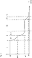
- the Figure 4 shows in a diagram the course of the internal pressure of the respective container 2 during the molding and filling phase and the subsequent relief phase depending on the time t.
- the internal pressure of the respective container is constant or essentially constant and corresponds to the molding and filling pressure p2 (for example in the range between 8 bar and 15 bar).
- the shaping and filling phase I after the end of the filling material flow can contain a pre-calming phase, the duration of which is, for example, 0.2 to 5 seconds.
- the form and filling phase I is followed by the in the Figure 4 reproduced method to a pre-relief phase II, the duration of which is, for example, at least 0.1 seconds and a maximum of 1 seconds and which is designed such that the internal pressure of the container 2 is reduced to the pre-relief pressure p1 during this pre-relief phase II or approaches this pre-relief pressure p1 asymptotically, which is, for example, in the range between 1.2 bar and 2.5 bar, for example when the containers 2 are shaped and filled with an already carbonized filling material in the range between 1.4 bar and 2.3 bar and when the layers are filled and molded container 2, for example with an initially CO2-free product with subsequent carbonization in the range between 1.3 bar and 1.7 bar and in this case preferably 1.4 to 1.6 bar.
- a pre-relief phase II the duration of which is, for example, at least 0.1 seconds and a maximum of 1 seconds and which is designed such that the internal pressure of the container 2 is reduced to the pre-relief pressure
- the duration of the pre-relief phase II is at least 0.1 seconds and a maximum of 1 second; the duration of the pre-relief phase II is preferably in the range between 0.2 and 0.4 seconds.
- the pre-relief phase II is followed by a calming phase III, in which the internal pressure of the container 2 is kept constant or essentially constant at the pre-relief pressure p1.
- gas bubbles of CO2 that are released rise in the filling material and are discharged into the ring bowl 15 with an isobaric internal pressure.
- the duration of the calming phase III is, for example, at least 0.5 seconds and a maximum of about 2 seconds, the duration of the calming phase III is preferably in the range between 0.6 and 1 second.
- a residual relief phase IV there is a relief to the ambient pressure p0 or a residual pressure slightly above the ambient pressure p0.
- the residual relief phase IV has a relatively steep pressure drop and has a duration of at least 0.05 seconds and a maximum of 0.5 seconds.
- the duration of the residual relief phase IV is preferably in the range between 0.08 and 0.15 seconds.
- the Figure 5 shows in a diagram the time dependence of the internal pressure of the container 2 during the form and filling phase I, the pre-relief phase II, the calming phase III, the residual relief phase IV and after the relief on the ambient pressure (curve section V). That in the Figure 5 method shown differs from the method of Figure 4 essentially only in that the preliminary relief is carried out in stages, so that the preliminary relief phase II has two sub-phases II.1 and II.2. During the pre-unloading, the respective container 2 is first relieved to a partial unloading pressure p1.1 after the completion of the forming and filling phase I and then finally to the pre-unloading pressure p1 in a further partial phase II.2.
- the pre-relief to the partial relief pressure p1.1 is carried out, for example, by brief opening and closing of the control valve 39, preferably taking into account a throttle provided in the gas channel 40 for this partial relief.
- the opening and closing of the valve which brings about partial relief, for example the control valve 39 takes place in a time-controlled manner and / or on the basis of measurement signals which are supplied by sensors which sense the internal pressure of the container 2.
- the partial relief pressure p1.1 is already significantly below the form and filling pressure p2 but sufficiently above the relief pressure p1.
- the distance between the partial relief pressure p1.1 and the pre-relief pressure p1 corresponds, for example, to a maximum of half the distance between the molding and filling pressure p2 and the pre-relief pressure p1: p 1.1 - p 1 ⁇ 1 / 2 ⁇ p 2 - p 1 ,
- the difference between the partial relief pressure p1.1 and the preliminary relief pressure p1 in phase II.1 is approximately 30% to 50% of the difference between the molding and filling pressure p2 and the preliminary relief pressure p1.
- the latter applies in particular when the containers 2 are shaped and filled with a carbonized filling material or with components of a carbonized filling material.
- the partial relief pressure p1.2 is the usual carbonation pressure, from 5 to 8 bar, the necessary partial relief pressure p1.2 also decreasing as the temperature of the filling material decreases.
- the Figure 6 shows in a diagram the time dependence of the internal pressure of the container 2 during the form and filling phase I, the pre-relief phase II with a carbonation phase II.3, the calming phase III, the residual relief phase IV and after the relief on the ambient pressure (curve section V). That in the Figure 6 method shown differs from the method of Figure 4 essentially only in that the preliminary relief in a first relief stage up to the carbonation pressure p1.2 is carried out, then the carbonation takes place with gaseous CO2 or liquid H2CO3, so that the pre-relief phase has a total of two partial relief stages II.1 and II.2, between which the carbonation phase lies.
- the pressure curve is shown in the diagram as isobaric, a slight increase in pressure occurring and tolerable during operation. A rest phase III. run through.
- the calming phase III takes place at this pre-relief pressure, the duration of which is at least 0.5 seconds and in exceptional cases a maximum of 4 seconds, usually in the range from 0.6 to 1. Is 5 seconds. This is followed by the quick residual relief phase
- the corresponding control times are among others transmitted empirically and / or taking into account various process parameters and e.g. stored in a data memory assigned to the molding and filling machine 10 or the system 1.
- the parameters essential for the cycle and control times are, for example, the rotational speed of the rotor 12, pressure, temperature and / or CO2 content of the filling material, size and / or shape of the container 2, stretching speed, etc.
- undesired air and / or gas residues present in the head space of the containers 2 are displaced, for example by a jet of an inert gas being introduced into the respective container 2 through at least one nozzle 42 through the container mouth 2.1 , for example, a nitrogen jet is introduced which not only fills the head space with the inert gas and thus removes undesired air and / or gas residues from the head space, but also causes controlled foaming in the case of a carbonized filling material, also to displace unwanted air. and / or steam and / or gas residues.
- a jet of an inert gas being introduced into the respective container 2 through at least one nozzle 42 through the container mouth 2.1
- a nitrogen jet is introduced which not only fills the head space with the inert gas and thus removes undesired air and / or gas residues from the head space, but also causes controlled foaming in the case of a carbonized filling material, also to displace unwanted air. and / or steam and / or gas residues.
Claims (21)
- Procédé de fabrication, à partir de préformes (3) en un matériau thermoplastique, de récipients (2) remplis, la préforme (3) respective étant au moins thermiquement conditionnée, après quoi elle est transformée au cours d'une phase de moulage et de remplissage en récipient (2) correspondant dans un moule (4.1) sous l'effet d'une pression de moulage et de remplissage (p2) exercée par le produit de remplissage qui y est amené, la préforme (3) étant, pendant la phase de moulage et de remplissage, temporairement au moins guidée et/ou étirée en sens axial (RA) par une barre d'étirage (27) et le récipient (2) respectif présentant au moins à la fin de la phase de moulage et de remplissage une pression intérieure correspondant à la pression de moulage et de remplissage (p2), caractérisé en ce que le récipient (2) moulé et rempli est, à l'achèvement de la phase de moulage et de remplissage (I), ramené à la pression atmosphérique ou ambiante (p0) au cours d'une phase de détente comportant au moins deux étapes (II - IV), le moulage et le remplissage du récipient (2) ayant lieu avec un produit de remplissage liquide non gazeux, c'est-à-dire ne contenant pas de CO2, et en ce que, après achèvement de la phase de moulage et de remplissage, une carbonation du produit de remplissage contenu dans le récipient est effectuée par introduction de CO2 gazeux ou d'H2CO3 liquide, de préférence après la réduction de la pression intérieure du récipient à une pression de carbonation et de pré-détente (p1.1) inférieure à la pression de moulage et de remplissage (p2).
- Procédé selon la revendication 1, caractérisé en ce que, après achèvement de la phase de moulage et de remplissage, la pression intérieure (p2) du récipient (2) moulé et rempli est réduite au cours d'une phase de pré-détente (II) comportant au moins une étape à une pression de pré-détente (p1) de par exemple environ 1,2 à 2,5 bars, qu'au cours d'une phase de stabilisation (III) qui suit la phase de pré-détente (II) la pression intérieure du récipient (2) est maintenue à une pression constante ou quasiment constante correspondant à la pression de pré-détente (p1), et qu'au cours d'une phase de détente finale (IV) comportant au moins une étape qui suit la (les) phase(s) de stabilisation (III) une détente ramène la pression du récipient (2) à la pression atmosphérique ou ambiante (p0).
- Procédé selon la revendication 2, caractérisé en ce que la variation dans le temps de la pression intérieure du récipient pendant la détente est choisie telle que la pente de la variation dans le temps à la fin d'au moins une phase, par exemple à la fin de la phase de pré-détente (II) est égale à la variation dans le temps de la pression au cours d'une phase suivante, par exemple de la (des) phase(s) de stabilisation (III), la transition entre la variation dans le temps de la pression intérieure du récipient à la fin de la phase de pré-détente et la variation dans le temps de la pression intérieure du récipient de la (des) phase(s) de stabilisation (III) se faisant de préférence avec une pente nulle ou quasiment nulle.
- Procédé selon l'une des revendications précédentes, caractérisé en ce que la phase de pré-détente (II) comporte au moins deux étapes avec au moins deux phases partielles (11.1, 11.2), la pression intérieure du récipient étant réduite au cours d'une première phase partielle (11.1) à une pression de détente partielle (p1.1), et que, par exemple, les variation dans le temps de la pression intérieure du récipient au cours des phases partielles (11.1, 11.2) diffèrent de par le gradient de la pression ou son évolution ou la variation dans le temps de la pente et/ou, par exemple, présentent une pente différente à la transition entre au moins les deux phases partielles (11.1, 11.2).
- Procédé selon l'une des revendications précédentes, caractérisé en ce que la pression intérieure de chaque récipient (2) après le moulage et le remplissage est maintenue au cours d'une phase de stabilisation supplémentaire à une pression constante ou quasiment constante correspondant à la pression de moulage et de remplissage (p2).
- Procédé selon l'une des revendications précédentes, caractérisé en ce que le moulage et le remplissage de chaque récipient (2) avec un produit de remplissage carbonisé sont effectués au cours d'au moins deux phases de processus de façon à introduire au cours de différentes phases du produit de remplissage avec différentes teneurs en CO2 et/ou à différentes températures, par exemple au cours d'une première phase du processus un composant (K1) du produit de remplissage sans CO2 ou avec une teneur en CO2 réduite et au cours d'une autre phase du processus un autre composant (K2) avec une teneur en CO2 accrue.
- Procédé selon la revendication 6, caractérisé en ce que le composant (K2) du produit de remplissage avec la concentration supérieure en CO2 a une température réduite par rapport à celle de l'autre composant (K1) et/ou est refroidi avant son introduction, et/ou en ce que le (les) composant(s) avec la concentration supérieure en CO2 est (sont) introduit(s) sous la couche de produit de remplissage déjà contenu dans le récipient (2) ou dans le récipient (2) en cours de formation.
- Procédé selon l'une des revendications précédentes, caractérisé en ce que la pression de moulage et de remplissage peut atteindre 20 bars et est idéalement de 8 à 15 bars, et/ou en ce que la pression de pré-détente est de 10 % à 30 % de la pression de moulage et de remplissage (p2), par exemple d'au moins 1,2 bar et de 2,5 bars au plus et de préférence réglée sur une valeur de 1,4 bar à 2,3 bars ou de 1,2 bar à 1,7 bar, et/ou en ce que la pression de détente partielle (p1.1) est au maximum égale à la demi-différence entre la pression de moulage et de remplissage (p2) et la pression de pré-détente (p1) et correspond de préférence à environ 30 % de cette différence et a une valeur de 6 bars à 8 bars.
- Procédé selon l'une des revendications précédentes, caractérisé en ce que la durée totale de la phase de pré-détente (II) est d'au moins 0,1 seconde et de 1,0 seconde au plus et de préférence comprise entre 0,2 et 0,4 seconde, et/ou en ce que la durée totale de la (des) phase(s) de stabilisation (III) qui sui(ven)t la phase de détente partielle (II) est d'au moins 0,5 seconde et de 2 secondes au plus et de préférence comprise entre 0,6 seconde et 1 seconde, et/ou en ce que la durée totale de la phase de détente finale (IV) est d'au moins 0,1 seconde et de 0,5 seconde au plus et de préférence comprise entre 0,1 seconde et 0,2 seconde.
- Procédé selon l'une des revendications précédentes, caractérisé en ce que la phase de moulage et de remplissage (I) et/ou la phase de détente (II) et/ou leurs phases partielles (11.1, 11.2) et/ou la (les) phase(s) de stabilisation (III) et/ou la (les) phases de détente finale (IV) sont commandées en fonction de la position de rotation d'un rotor (12) présentant une pluralité de moules (4.1) et pouvant être entraîné en un mouvement de rotation autour d'un axe vertical de la machine (MA) et/ou sont commandées en fonction du temps, la commande tenant de préférence compte entre autres de paramètres afférents au produit de remplissage et/ou de paramètres spécifiques du récipient, par exemple la nature et/ou la température et/ou la teneur en CO2 du produit de remplissage, la valeur de la pression de moulage et de remplissage (p2), les dimensions et la nature des récipients (2), et la commande en fonction du temps étant contrôlée et/ou corrigée par ex. par des détecteurs qui détectent par exemple la quantité de produit de remplissage qui afflue et/ou la température et la pression.
- Procédé selon l'une des revendications précédentes, caractérisé en ce que la durée de détente des récipients (2) respectifs pour réduire la pression de moulage et de remplissage (p2) et la ramener à la pression ambiante (p0) est réglée en fonction de la température du produit de remplissage, et ce notamment par variation de la durée de détente et/ou de celle de ses phases partielles et/ou du niveau de la pression de pré-détente et/ou de la (des) pression(s) de détente partielle, la durée de détente et/ou la durée d'au moins une phase partielle de détente augmentant avec la température du produit de remplissage.
- Procédé selon l'une des revendications précédentes, caractérisé en ce que les niveaux de pression à choisir pour la détente et/ou la carbonation des récipients (2) respectifs et la réduction de la pression de moulage et de remplissage (p2) au niveau de la pression ambiante (p0) sont réglés en fonction de la température du produit de remplissage, et ce notamment par variation des niveaux de pression de carbonation (p1.2) et/ou de la (des) pression(s) de détente partielle, les niveaux de pression requis augmentant avec la température du produit de remplissage.
- Procédé selon l'une des revendications précédentes, caractérisé en ce que l'espace intérieur de la préforme (3) est rincé avec un gaz inerte avant la phase de moulage et de remplissage, par exemple avec du CO2, et/ou en ce que la préforme (3) est soumise en début de phase de moulage et de remplissage à une précontrainte avec un gaz inerte, par exemple avec du CO2, de préférence avec une pression qui correspond ou correspond quasiment à la pression de moulage et de remplissage (p2), et/ou en ce qu'au moins les surfaces intérieures de la préforme (3) sont stérilisées avant la phase de moulage et de remplissage.
- Dispositif de fabrication de récipients (2) remplis d'un produit liquide à partir de préformes (3) en un matériau thermoplastique au moins thermiquement conditionnées, avec au moins une station de moulage et de remplissage (4), avec au moins un conduit (31, 36, 37) pour liquides pour l'adduction contrôlée du produit de remplissage destiné à former et remplir le récipient (2) et provenant d'au moins une cuve (13, 14) pour produit de remplissage qu'elle contient sous pression de moulage et de remplissage (p2), la station de moulage et de remplissage (4) présentant une barre d'étirage (27) pour guider et étirer la préforme (3) correspondante temporairement au moins pendant la phase de moulage et de remplissage (I), le conduit (36) pour liquides étant en partie au moins formée par un canal (31) dans la barre d'étirage (27), et la station de moulage et de remplissage (4) présentant une surface de contact (28, 27) annulaire contre laquelle la préforme (3) et le récipient (2) qui se forme à partir de celle-ci s'appuient en position étanche au moins pendant la phase de moulage et de remplissage, caractérisé par au moins un conduit de gaz commandé (39, 40) qui, par au moins un canal de retour de gaz (38), par exemple un canal de retour de gaz (38) qui entoure annulairement la barre d'étirage (27), aboutit à l'intérieur de la surface de contact annulaire (28, 29), le dispositif étant conçu pour réaliser le moulage et le remplissage des récipients (2) avec un produit de remplissage liquide non gazeux, c'est-à-dire ne contenant pas de CO2, et, après achèvement de la phase de moulage et de remplissage, effectuer une carbonation du produit de remplissage contenu dans le récipient par introduction de CO2 gazeux ou d'H2CO3 liquide, de préférence après la réduction de la pression intérieure du récipient à une pression de carbonation et de pré-détente (p1.1) inférieure à la pression de moulage et de remplissage (p2).
- Dispositif selon la revendication 14, caractérisé en ce que le (les) conduits de gaz (23, 40) présente(nt) au moins un élément (24, 25, 39) permettant de régler ou de commander en continu la pression (p1) et/ou le débit volumétrique du gaz.
- Dispositif selon la revendication 14 ou 15, caractérisé en ce que le conduit de gaz (23, 40) est relié à un volume tampon, par exemple sous forme d'une cuve ou d'une cuve annulaire (15) ou sous forme d'une conduite annulaire, et en ce que le volume tampon est connecté à un dispositif de commande ou de régulation de la pression.
- Dispositif selon l'une des revendications précédentes 14 à 16, caractérisé en ce que la (les) cuve(s) de produit de remplissage est (sont) réalisée(s) sous forme de cuve annulaire (13, 14) ou de conduite annulaire, et ce avec un volume correspondant à un multiple du volume de remplissage d'un récipient (2).
- Dispositif selon l'une des revendications précédentes 14 à 17, caractérisé en ce que les stations de moulage et de remplissage (4) équipent un rotor (12) pouvant être entraîné en un mouvement de rotation autour d'un axe vertical de la machine (MA), et en ce que le rotor est équipé de la (des) cuve(s) de produit de remplissage (13, 14) et/ou de la cuve (15) constituant le volume tampon.
- Dispositif selon l'une des revendications précédentes 14 à 18, caractérisé en ce qu'est prévue au moins une unité de refroidissement permettant de refroidir au moins une conduite d'adduction de produit de remplissage et/ou d'un composant du produit de remplissage et/ou la cuve de produit de remplissage, et notamment en ce qu'il est possible de mettre hors circuit la (les) unité(s) de refroidissement et/ou d'en régler la puissance de refroidissement en fonction de la température du produit.
- Dispositif selon la revendication 19, caractérisé en ce qu'est prévue une unité de détection 43, laquelle est connectée à l'unité de commande 20 par des lignes de transmission données 44 ou par des liaisons de transmission de données sans fil et permettant de détecter des niveaux de remplissage et caractéristiques de marche DE CONSIGNE et EFFECTIFS et/ou la formation de mousse, et notamment en ce que l'unité de détection comprend un détecteur acoustique et/ou de vibrations comme par exemple un détecteur piézo-électrique.
- Dispositif selon l'une des revendications précédentes 14 à 20, caractérisé en ce que sont prévus des capteurs de pression et des dispositifs de condensation et/ou de compression et/ou des valves réglables au moyen desquels les niveaux de pression de toutes les phases de processus peuvent être modifiés pendant le fonctionnement de la machine.
Applications Claiming Priority (6)
| Application Number | Priority Date | Filing Date | Title |
|---|---|---|---|
| DE102011009889A DE102011009889A1 (de) | 2011-01-31 | 2011-01-31 | Verfahren und Vorrichtung zur Herstellung von gefüllten Behältern |
| DE102011009888A DE102011009888A1 (de) | 2011-01-31 | 2011-01-31 | Verfahren und Vorrichtung zur Herstellung von gefüllten Behältern |
| DE102011011076A DE102011011076A1 (de) | 2011-02-11 | 2011-02-11 | Verfahren sowie Vorrichtung zum Herstellen von mit einem flüssigen Füllgut gefüllten Behältern |
| DE102011012664A DE102011012664A1 (de) | 2011-02-28 | 2011-02-28 | Verfahren und Vorrichtung zur Herstellung von mit einem flüssigen Füllgut gefüllten Behältern |
| DE102011012665A DE102011012665A1 (de) | 2011-02-28 | 2011-02-28 | Verfahren sowie Vorrichtung zum Herstellen von mit einem flüssigen Füllgut gefüllten Behältern |
| PCT/EP2012/000163 WO2012104018A1 (fr) | 2011-01-31 | 2012-01-17 | Procédé et dispositif pour fabriquer des contenants remplis d'un liquide de remplissage |
Publications (2)
| Publication Number | Publication Date |
|---|---|
| EP2670668A1 EP2670668A1 (fr) | 2013-12-11 |
| EP2670668B1 true EP2670668B1 (fr) | 2020-03-04 |
Family
ID=45509443
Family Applications (3)
| Application Number | Title | Priority Date | Filing Date |
|---|---|---|---|
| EP11782059.7A Active EP2670666B1 (fr) | 2011-01-31 | 2011-11-08 | Procédé et appareil pour fabriquer de récipients remplis d'un liquide |
| EP12700781.3A Active EP2670668B1 (fr) | 2011-01-31 | 2012-01-17 | Procédé et dispositif de fabrication de récipients remplis avec un produit liquide |
| EP12700607.0A Active EP2670667B1 (fr) | 2011-01-31 | 2012-01-17 | Procédé et dispositif de fabrication de récipients remplis avec un produit liquide |
Family Applications Before (1)
| Application Number | Title | Priority Date | Filing Date |
|---|---|---|---|
| EP11782059.7A Active EP2670666B1 (fr) | 2011-01-31 | 2011-11-08 | Procédé et appareil pour fabriquer de récipients remplis d'un liquide |
Family Applications After (1)
| Application Number | Title | Priority Date | Filing Date |
|---|---|---|---|
| EP12700607.0A Active EP2670667B1 (fr) | 2011-01-31 | 2012-01-17 | Procédé et dispositif de fabrication de récipients remplis avec un produit liquide |
Country Status (4)
| Country | Link |
|---|---|
| US (3) | US10696434B2 (fr) |
| EP (3) | EP2670666B1 (fr) |
| CN (3) | CN103635389B (fr) |
| WO (3) | WO2012103905A1 (fr) |
Families Citing this family (51)
| Publication number | Priority date | Publication date | Assignee | Title |
|---|---|---|---|---|
| US8740609B2 (en) * | 2011-06-09 | 2014-06-03 | Amcor Limited | CSD cooling and pressurization to keep CO2 in solution during forming |
| ITBO20110691A1 (it) | 2011-12-02 | 2013-06-03 | Ativa | Linea e procedimento di imbottigliamento in ciclo continuo di contenitori in materiale termoplastico. |
| TWM445984U (zh) * | 2012-07-18 | 2013-02-01 | Can Pack Commercial Co Ltd | 微波容器殺菌設備 |
| DE102012015086A1 (de) * | 2012-08-01 | 2014-02-06 | Khs Corpoplast Gmbh | Verfahren sowie Vorrichtung zum Herstellen von mit einem flüssigen Füllgut gefüllten Behältern |
| US10479536B2 (en) * | 2012-09-17 | 2019-11-19 | Portland Outdoors, Llc | System, methods and apparatus for urine collection and storage |
| DE102012021997A1 (de) * | 2012-11-12 | 2014-05-15 | Krones Ag | Verfahren zum Herstellen von Getränkebehältnissen und Vorrichtung zum Herstellen von Getränkebehältnissen |
| JP5808733B2 (ja) * | 2012-12-28 | 2015-11-10 | 株式会社吉野工業所 | ブロー成形装置 |
| EP3013557B1 (fr) * | 2013-06-28 | 2021-02-17 | Discma AG | Broche d'étanchéité à circulation à deux étages |
| EP3013554B1 (fr) | 2013-06-28 | 2018-08-01 | Discma AG | Système et procédé en deux étapes pour le moulage de récipients |
| US9987789B2 (en) | 2013-06-28 | 2018-06-05 | Discma Ag | Liquid jet diameter control |
| CN105682886B (zh) * | 2013-09-18 | 2020-08-11 | 三菱重工机械系统株式会社 | 吹塑成型装置 |
| JP6439920B2 (ja) * | 2013-11-14 | 2018-12-19 | 大日本印刷株式会社 | ボトルの殺菌方法及び装置 |
| DE102013019892B4 (de) | 2013-11-28 | 2022-03-10 | Krones Ag | Hohlkörperherstellungsmaschine und Verfahren zum Umformen eines Vorformlings |
| EP2889229B1 (fr) * | 2013-12-31 | 2016-09-21 | Sidel S.p.a. Con Socio Unico | Machine de traitement de récipients ayant une architecture de commande améliorée |
| DE102014004354A1 (de) * | 2014-03-27 | 2015-10-01 | Khs Corpoplast Gmbh | Verfahren und Vorrichtung zum Herstellen eines mit Füllgut gefüllten Behälters |
| DE102014104874A1 (de) * | 2014-04-04 | 2015-10-08 | Krones Ag | Vorrichtung und Verfahren zur Herstellung einer Kunststoffflasche und deren Befüllung mit einem Füllprodukt |
| EP2987731B1 (fr) * | 2014-08-20 | 2017-06-28 | Krones AG | Remplisseuse de moule pour un récipient en plastique |
| EP2987766B1 (fr) * | 2014-08-20 | 2017-04-05 | Krones AG | Correction de hauteur de remplissage |
| EP2987607B1 (fr) | 2014-08-20 | 2017-06-07 | Krones AG | Procédé de moulage et remplissage |
| EP3109029B1 (fr) | 2015-06-25 | 2017-12-13 | Discma AG | Station de formage pour former un récipient à partir d'une préforme comprenant une tige d'étirage vibrante, méthode de fabrication d'un récipient utilisant ladite station de formage, méthode d'élimination de la mousse dans le col d'un container utilisant ladite station de formage et méthode de nettoayge de la station de formage. |
| EP3109032A1 (fr) * | 2015-06-25 | 2016-12-28 | Discma AG | Procédé de formation d'un récipient à partir d'une préforme dans laquelle la paroi de la préforme est mise en vibration pendant ladite formation |
| FR3042149B1 (fr) * | 2015-10-08 | 2017-11-03 | Sidel Participations | Procede de formation d’un emballage a partir d’un recipient, comprenant une phase de controle thermique |
| DE102015014462A1 (de) * | 2015-11-11 | 2017-05-11 | Khs Corpoplast Gmbh | Vorrichtung zum gleichzeitigen Formen und Füllen von Behältern aus Vorformlingen, Ventilanordnung und Verwendung einer solchen Ventilanordnung in einem Verfahren zum gleichzeitigen Formen und Füllen von Behältern aus Vorformlingen |
| JP6605312B2 (ja) * | 2015-11-27 | 2019-11-13 | 株式会社吉野工業所 | 液体ブロー成形方法 |
| JP6632872B2 (ja) * | 2015-11-27 | 2020-01-22 | 株式会社吉野工業所 | 液体ブロー成形方法 |
| EP3390231A1 (fr) * | 2015-12-14 | 2018-10-24 | KHS Corpoplast GmbH | Procédé et dispositif de fabrication de contenants remplis d'un produit de remplissage liquide à partir d'ébauches au moyen d'une matière de remplissage introduite sous pression dans l'ébauche |
| EP3202704B1 (fr) | 2016-02-08 | 2018-09-26 | Sidel Participations | Procédé pour détecter l'état défectueux d'un article à contact rempli d'un produit fluide et dispositif de remplissage |
| DE102017103438A1 (de) * | 2017-02-20 | 2018-08-23 | Khs Corpoplast Gmbh | Verfahren und Vorrichtung zur Trocknung von auf einem rotierenden Blasrad angeordneten Blasformen zur Vermeidung von Kondenswasserbildung |
| DE102017105324A1 (de) | 2017-03-14 | 2018-09-20 | Khs Gmbh | Füllmaschine |
| DE102017003410A1 (de) | 2017-04-07 | 2018-10-11 | Khs Corpoplast Gmbh | Verfahren sowie Vorrichtung zum Herstellen von mit einem flüssigen Füllgut gefüllten und mit einer Verschlusskappe verschlossenen Behältern |
| DE102017111066A1 (de) * | 2017-05-22 | 2018-11-22 | Khs Gmbh | Verfahren zur Überwachung eines Prozesses |
| WO2019013754A1 (fr) * | 2017-07-10 | 2019-01-17 | Amcor Group Gmbh | Procédé et système de débit de goupille d'étanchéité |
| DE102017008446A1 (de) * | 2017-09-08 | 2019-03-14 | Khs Corpoplast Gmbh | Verfahren, Vorrichtung, Arbeitsrad und Umformstation für die Herstellung von gefüllten Behältern aus temperaturkonditionierten Vorformlingen |
| DE102017010272B3 (de) | 2017-11-07 | 2019-03-21 | Khs Corpoplast Gmbh | Form- und Füllstation einer Anlage zum Herstellen von gefüllten Behältern aus Vorformlingen durch unter Druck in den Vorformling eingeleitetes Füllgut |
| DE102017011354A1 (de) * | 2017-12-07 | 2019-06-13 | Kocher-Plastik Maschinenbau Gmbh | Verfahren und Vorrichtung zum Verbinden von mindestens zwei Kunststoffteilen |
| JP6893870B2 (ja) * | 2017-12-28 | 2021-06-23 | 株式会社吉野工業所 | 液体入り容器の製造方法 |
| US11198243B2 (en) | 2018-01-11 | 2021-12-14 | Husky Injection Molding Systems Ltd. | Method and apparatus for forming final-shaped containers using liquid to be contained therein |
| DE102018105229A1 (de) * | 2018-03-07 | 2019-09-12 | Krones Ag | Vorrichtung und Verfahren zum Expandieren und gleichzeitigen Befüllen von Behältnissen |
| DE102018106930A1 (de) * | 2018-03-23 | 2019-09-26 | Krones Aktiengesellschaft | Vorrichtung zum Umformen und Befüllen von Kunststoffbehältnissen mit gesteuerter Einfüllung |
| DE102018107676A1 (de) | 2018-03-29 | 2019-10-02 | Khs Corpoplast Gmbh | Verfahren und Vorrichtung zum Herstellen eines Behälters aus einem thermoplastischen Vorformling |
| DE102018108760A1 (de) | 2018-04-12 | 2019-10-17 | Khs Corpoplast Gmbh | Verfahren und Vorrichtung zum Befüllen von Behältern mit karbonisiertem Füllgut und dem anschließenden Verschließen der gefüllten Behälter |
| DE102018113435B4 (de) | 2018-06-06 | 2021-07-15 | Khs Gmbh | Vorrichtung und Verfahren zur Behandlung von mit aufschäumbarem flüssigen Füllgut befüllten Behältern |
| JP7174057B2 (ja) * | 2018-08-30 | 2022-11-17 | 株式会社吉野工業所 | 液体入り容器の製造方法 |
| JP7026595B2 (ja) * | 2018-08-31 | 2022-02-28 | 株式会社吉野工業所 | 液体入り容器の製造方法及び製造装置 |
| EP3898155A1 (fr) | 2018-12-19 | 2021-10-27 | The Procter & Gamble Company | Article à effet visuel |
| CN113165214A (zh) | 2018-12-19 | 2021-07-23 | 宝洁公司 | 具有功能、视觉和/或触觉效果的单层吹塑制品以及制造此类制品的方法 |
| DE102019114953A1 (de) * | 2019-06-04 | 2020-12-10 | Khs Corpoplast Gmbh | Verfahren und Vorrichtung zum Herstellen von mit flüssigem Füllgut befüllten Behältern aus thermisch konditionierten Vorformlingen |
| CN110155923A (zh) * | 2019-07-09 | 2019-08-23 | 佛山克情日用品有限公司 | 一种具有灭菌功能的瓶口封口装置 |
| DE102019130052A1 (de) * | 2019-11-07 | 2021-05-12 | Khs Gmbh | Verfahren zum Befüllen und Verschließen von Behältern |
| DE102020130535A1 (de) * | 2020-11-19 | 2022-05-19 | Krones Ag | Abfüllanlage für flüssige Produkte und Verfahren zur Abfüllung flüssiger Produkte in Flaschen |
| DE102022117725A1 (de) * | 2022-07-15 | 2024-01-18 | Krones Aktiengesellschaft | Anlage und Verfahren zum Betreiben einer Anlage zum Herstellen von befüllten Kunststoffbehältnissen aus sterilen Kunststoffvorformlingen |
Family Cites Families (31)
| Publication number | Priority date | Publication date | Assignee | Title |
|---|---|---|---|---|
| DE2209494A1 (de) * | 1972-02-29 | 1973-09-13 | Pmd Entwicklungswerk | Blas- und fuelldorn |
| DE2352926A1 (de) | 1973-10-22 | 1975-04-24 | Heidenreich & Harbeck Gmbh | Verfahren und vorrichtung zum erwaermen eines werkstueckes aus kunststoff |
| GB1474044A (en) * | 1974-12-03 | 1977-05-18 | Ici Ltd | Plastics container manufacture |
| DE3420711A1 (de) * | 1984-06-02 | 1985-12-05 | Tetra Pak Developpement S.A., Pully | Maschine zur herstellung von fliessmittelpackungen |
| CA1288913C (fr) | 1986-09-22 | 1991-09-17 | Prakash R. Ajmera | Methode et dispositif de faconnage d'un contenant plastique thermodurci, a structure partiellement cristalline et orientation bi-axiale |
| US4883631A (en) | 1986-09-22 | 1989-11-28 | Owens-Illinois Plastic Products Inc. | Heat set method for oval containers |
| DE3807046A1 (de) | 1988-03-04 | 1989-10-12 | Seitz Enzinger Noll Masch | Verfahren und vorrichtung zum abfuellen von kohlensaeurehaltigen fluessigkeiten, insbesondere getraenken, unter gegendruck in gefaesse oder dgl. |
| US5035931A (en) * | 1988-09-12 | 1991-07-30 | Dai Nippon Insatsu K.K. | Multi-layer parison, multi-layer bottle and apparatus for and method of manufacturing parison and bottle |
| IT1227845B (it) * | 1988-12-27 | 1991-05-08 | Gemmo Gabriella | Procedimento a piu' fasi per il riempimento di contenitori con liquidi gassati |
| DE4212583A1 (de) | 1992-04-15 | 1993-10-21 | Krupp Corpoplast Masch | Vorrichtung zur Blasformung |
| DE4340291A1 (de) | 1993-11-26 | 1995-06-01 | Krupp Corpoplast Masch | Mehrfachnutzung von Blasluft |
| CA2191093C (fr) | 1995-03-27 | 2000-08-22 | Kurt H. Ruppman, Sr. | Procede de fabrication d'un recipient en plastique moule |
| JP2000043129A (ja) * | 1998-07-29 | 2000-02-15 | Ishikawajima Harima Heavy Ind Co Ltd | プラスチック容器の成形方法 |
| US6485669B1 (en) | 1999-09-14 | 2002-11-26 | Schmalbach-Lubeca Ag | Blow molding method for producing pasteurizable containers |
| US6485670B1 (en) | 1999-11-09 | 2002-11-26 | Schmalbach-Lubeca Ag | Blow molding method for producing pasteurizable containers |
| US20020048642A1 (en) | 2000-09-07 | 2002-04-25 | Beck Martin H. | Production of crystallizable polymer blow molded containers having a crystallized interior |
| FR2839277B1 (fr) | 2002-05-03 | 2005-04-08 | Nestle Waters Man & Technology | Procede de fabrication d'un contenant en resine polyester et dispositif pour sa mise en oeuvre |
| ITPR20020080A1 (it) * | 2002-12-23 | 2004-06-24 | Procomac Spa | Valvola riempitrice, in particolare per liquidi caldi. |
| DE102004041973B3 (de) * | 2004-08-31 | 2006-01-19 | Krones Ag | Luftrecycling im Blasformprozess |
| ATE465089T1 (de) * | 2005-07-28 | 2010-05-15 | Krones Ag | Vorrichtung und verfahren zum abfüllen |
| GB2431372A (en) | 2005-10-18 | 2007-04-25 | Ebac Ltd | Apparatus and method for blow moulding articles |
| US7914726B2 (en) * | 2006-04-13 | 2011-03-29 | Amcor Limited | Liquid or hydraulic blow molding |
| DE102006049163A1 (de) * | 2006-10-18 | 2008-05-08 | Sig Technology Ag | Verfahren und Vorrichtung zur Blasformung von Behältern |
| US8017064B2 (en) * | 2007-12-06 | 2011-09-13 | Amcor Limited | Liquid or hydraulic blow molding |
| EP2143542A1 (fr) * | 2008-07-07 | 2010-01-13 | Nestec S.A. | Procédé et dispositif de conditionnement d'un liquide alimentaire |
| DE102008057999A1 (de) * | 2008-11-13 | 2010-05-20 | Khs Corpoplast Gmbh & Co. Kg | Verfahren und Vorrichtung zur Blasformung von Behältern |
| DE102009011583A1 (de) * | 2009-03-06 | 2010-09-09 | Krones Ag | Verfahren und Vorrichtung zum Herstellen und Befüllen von dünnwandigen Getränkebehältern |
| DE102009040803A1 (de) * | 2009-08-25 | 2011-04-14 | Khs Corpoplast Gmbh & Co. Kg | Verfahren und Vorrichtung zur Blasformung von Behältern |
| DE102009041215A1 (de) * | 2009-09-11 | 2011-03-24 | Krones Ag | Verfahren und Vorrichtung zum Streckblasformen oder Blasformen und Füllen steriler Behälter |
| US8507063B2 (en) * | 2009-09-22 | 2013-08-13 | Graham Packaging Lc, L.P. | Pet containers with enhanced thermal properties |
| DE102010007541A1 (de) | 2009-12-23 | 2011-06-30 | KHS Corpoplast GmbH, 22145 | Verfahren und Vorrichtung zur Herstellung von gefüllten Behältern |
-
2011
- 2011-11-08 CN CN201180069863.9A patent/CN103635389B/zh active Active
- 2011-11-08 EP EP11782059.7A patent/EP2670666B1/fr active Active
- 2011-11-08 US US13/982,800 patent/US10696434B2/en active Active
- 2011-11-08 WO PCT/EP2011/005596 patent/WO2012103905A1/fr active Application Filing
-
2012
- 2012-01-17 US US13/982,814 patent/US9278770B2/en active Active
- 2012-01-17 WO PCT/EP2012/000164 patent/WO2012104019A1/fr active Application Filing
- 2012-01-17 CN CN201280017121.6A patent/CN103648910B/zh active Active
- 2012-01-17 WO PCT/EP2012/000163 patent/WO2012104018A1/fr active Application Filing
- 2012-01-17 US US13/982,823 patent/US9718567B2/en active Active
- 2012-01-17 EP EP12700781.3A patent/EP2670668B1/fr active Active
- 2012-01-17 CN CN201280016965.9A patent/CN103476679B/zh active Active
- 2012-01-17 EP EP12700607.0A patent/EP2670667B1/fr active Active
Non-Patent Citations (1)
| Title |
|---|
| None * |
Also Published As
| Publication number | Publication date |
|---|---|
| CN103648910A (zh) | 2014-03-19 |
| US20130307197A1 (en) | 2013-11-21 |
| WO2012104019A1 (fr) | 2012-08-09 |
| EP2670667B1 (fr) | 2017-12-13 |
| CN103476679A (zh) | 2013-12-25 |
| EP2670667A1 (fr) | 2013-12-11 |
| US20140157726A1 (en) | 2014-06-12 |
| CN103648910B (zh) | 2016-08-17 |
| US10696434B2 (en) | 2020-06-30 |
| CN103635389A (zh) | 2014-03-12 |
| EP2670668A1 (fr) | 2013-12-11 |
| CN103635389B (zh) | 2016-04-13 |
| EP2670666B1 (fr) | 2020-03-04 |
| WO2012104018A1 (fr) | 2012-08-09 |
| US9718567B2 (en) | 2017-08-01 |
| EP2670666A1 (fr) | 2013-12-11 |
| CN103476679B (zh) | 2017-03-01 |
| WO2012103905A1 (fr) | 2012-08-09 |
| US20130313761A1 (en) | 2013-11-28 |
| WO2012103905A8 (fr) | 2013-10-24 |
| US9278770B2 (en) | 2016-03-08 |
Similar Documents
| Publication | Publication Date | Title |
|---|---|---|
| EP2670668B1 (fr) | Procédé et dispositif de fabrication de récipients remplis avec un produit liquide | |
| DE102011011076A1 (de) | Verfahren sowie Vorrichtung zum Herstellen von mit einem flüssigen Füllgut gefüllten Behältern | |
| EP2930138B1 (fr) | Dispositif et procédé de fabrication d'une bouteille en plastique et de son remplissage d'un produit de remplissage | |
| EP2516133B1 (fr) | Procede et dispositif de fabrication de recipients remplis | |
| EP2958732B1 (fr) | Procédé et dispositif de fabrication et de remplissage de contenants | |
| EP1727661B1 (fr) | Procede et dispositif pour produire un corps creux en reduisant la consommation d' air | |
| EP2879960B1 (fr) | Procédé et dispositif de fabrication de contenants remplis d'un produit liquide | |
| WO2014127876A1 (fr) | Procédé et dispositif de fabrication et de remplissage de récipients | |
| EP2879959B1 (fr) | Procédé et dispositif pour produire des contenants remplis d'une matière de remplissage liquide | |
| DE102011012751B4 (de) | Verfahren sowie Anlage zu Herstellung von mit einem flüssigen Füllgut gefüllten Behältern | |
| WO2016066276A1 (fr) | Procédé permettant de chasser l'air d'ébauches aux fins de fabrication de contenants plastique remplis | |
| DE102011012664A1 (de) | Verfahren und Vorrichtung zur Herstellung von mit einem flüssigen Füllgut gefüllten Behältern | |
| EP2987610B1 (fr) | Remplisseuse de moule destinée à fabriquer et à remplir des récipients en plastique par recyclage de CO2 | |
| DE102011009889A1 (de) | Verfahren und Vorrichtung zur Herstellung von gefüllten Behältern | |
| DE102011012665A1 (de) | Verfahren sowie Vorrichtung zum Herstellen von mit einem flüssigen Füllgut gefüllten Behältern | |
| WO2017093078A1 (fr) | Procédé de remplissage de récipients en matière plastique fabriqués par étirage-soufflage | |
| WO2019002468A1 (fr) | Dispositif de traitement d'un récipient dans une installation de mise en bouteille d'un produit de remplissage | |
| EP3012087B1 (fr) | Machine de fabrication de corps creux | |
| DE102018219119A1 (de) | Verfahren zum Gegendruckfüllen von Behältern und Füllsystem eines Gegendruckfüllers | |
| DE102011009888A1 (de) | Verfahren und Vorrichtung zur Herstellung von gefüllten Behältern |
Legal Events
| Date | Code | Title | Description |
|---|---|---|---|
| PUAI | Public reference made under article 153(3) epc to a published international application that has entered the european phase |
Free format text: ORIGINAL CODE: 0009012 |
|
| 17P | Request for examination filed |
Effective date: 20130822 |
|
| AK | Designated contracting states |
Kind code of ref document: A1 Designated state(s): AL AT BE BG CH CY CZ DE DK EE ES FI FR GB GR HR HU IE IS IT LI LT LU LV MC MK MT NL NO PL PT RO RS SE SI SK SM TR |
|
| DAX | Request for extension of the european patent (deleted) | ||
| 17Q | First examination report despatched |
Effective date: 20160830 |
|
| STAA | Information on the status of an ep patent application or granted ep patent |
Free format text: STATUS: EXAMINATION IS IN PROGRESS |
|
| GRAP | Despatch of communication of intention to grant a patent |
Free format text: ORIGINAL CODE: EPIDOSNIGR1 |
|
| STAA | Information on the status of an ep patent application or granted ep patent |
Free format text: STATUS: GRANT OF PATENT IS INTENDED |
|
| INTG | Intention to grant announced |
Effective date: 20190918 |
|
| RAP1 | Party data changed (applicant data changed or rights of an application transferred) |
Owner name: KHS GMBH |
|
| GRAS | Grant fee paid |
Free format text: ORIGINAL CODE: EPIDOSNIGR3 |
|
| GRAA | (expected) grant |
Free format text: ORIGINAL CODE: 0009210 |
|
| STAA | Information on the status of an ep patent application or granted ep patent |
Free format text: STATUS: THE PATENT HAS BEEN GRANTED |
|
| AK | Designated contracting states |
Kind code of ref document: B1 Designated state(s): AL AT BE BG CH CY CZ DE DK EE ES FI FR GB GR HR HU IE IS IT LI LT LU LV MC MK MT NL NO PL PT RO RS SE SI SK SM TR |
|
| REG | Reference to a national code |
Ref country code: GB Ref legal event code: FG4D Free format text: NOT ENGLISH |
|
| REG | Reference to a national code |
Ref country code: CH Ref legal event code: EP |
|
| REG | Reference to a national code |
Ref country code: AT Ref legal event code: REF Ref document number: 1240101 Country of ref document: AT Kind code of ref document: T Effective date: 20200315 |
|
| REG | Reference to a national code |
Ref country code: DE Ref legal event code: R096 Ref document number: 502012015828 Country of ref document: DE |
|
| REG | Reference to a national code |
Ref country code: IE Ref legal event code: FG4D Free format text: LANGUAGE OF EP DOCUMENT: GERMAN |
|
| PG25 | Lapsed in a contracting state [announced via postgrant information from national office to epo] |
Ref country code: FI Free format text: LAPSE BECAUSE OF FAILURE TO SUBMIT A TRANSLATION OF THE DESCRIPTION OR TO PAY THE FEE WITHIN THE PRESCRIBED TIME-LIMIT Effective date: 20200304 Ref country code: NO Free format text: LAPSE BECAUSE OF FAILURE TO SUBMIT A TRANSLATION OF THE DESCRIPTION OR TO PAY THE FEE WITHIN THE PRESCRIBED TIME-LIMIT Effective date: 20200604 Ref country code: RS Free format text: LAPSE BECAUSE OF FAILURE TO SUBMIT A TRANSLATION OF THE DESCRIPTION OR TO PAY THE FEE WITHIN THE PRESCRIBED TIME-LIMIT Effective date: 20200304 |
|
| REG | Reference to a national code |
Ref country code: NL Ref legal event code: MP Effective date: 20200304 |
|
| PG25 | Lapsed in a contracting state [announced via postgrant information from national office to epo] |
Ref country code: BG Free format text: LAPSE BECAUSE OF FAILURE TO SUBMIT A TRANSLATION OF THE DESCRIPTION OR TO PAY THE FEE WITHIN THE PRESCRIBED TIME-LIMIT Effective date: 20200604 Ref country code: GR Free format text: LAPSE BECAUSE OF FAILURE TO SUBMIT A TRANSLATION OF THE DESCRIPTION OR TO PAY THE FEE WITHIN THE PRESCRIBED TIME-LIMIT Effective date: 20200605 Ref country code: HR Free format text: LAPSE BECAUSE OF FAILURE TO SUBMIT A TRANSLATION OF THE DESCRIPTION OR TO PAY THE FEE WITHIN THE PRESCRIBED TIME-LIMIT Effective date: 20200304 Ref country code: SE Free format text: LAPSE BECAUSE OF FAILURE TO SUBMIT A TRANSLATION OF THE DESCRIPTION OR TO PAY THE FEE WITHIN THE PRESCRIBED TIME-LIMIT Effective date: 20200304 Ref country code: LV Free format text: LAPSE BECAUSE OF FAILURE TO SUBMIT A TRANSLATION OF THE DESCRIPTION OR TO PAY THE FEE WITHIN THE PRESCRIBED TIME-LIMIT Effective date: 20200304 |
|
| REG | Reference to a national code |
Ref country code: LT Ref legal event code: MG4D |
|
| PG25 | Lapsed in a contracting state [announced via postgrant information from national office to epo] |
Ref country code: NL Free format text: LAPSE BECAUSE OF FAILURE TO SUBMIT A TRANSLATION OF THE DESCRIPTION OR TO PAY THE FEE WITHIN THE PRESCRIBED TIME-LIMIT Effective date: 20200304 |
|
| PG25 | Lapsed in a contracting state [announced via postgrant information from national office to epo] |
Ref country code: EE Free format text: LAPSE BECAUSE OF FAILURE TO SUBMIT A TRANSLATION OF THE DESCRIPTION OR TO PAY THE FEE WITHIN THE PRESCRIBED TIME-LIMIT Effective date: 20200304 Ref country code: SM Free format text: LAPSE BECAUSE OF FAILURE TO SUBMIT A TRANSLATION OF THE DESCRIPTION OR TO PAY THE FEE WITHIN THE PRESCRIBED TIME-LIMIT Effective date: 20200304 Ref country code: PT Free format text: LAPSE BECAUSE OF FAILURE TO SUBMIT A TRANSLATION OF THE DESCRIPTION OR TO PAY THE FEE WITHIN THE PRESCRIBED TIME-LIMIT Effective date: 20200729 Ref country code: ES Free format text: LAPSE BECAUSE OF FAILURE TO SUBMIT A TRANSLATION OF THE DESCRIPTION OR TO PAY THE FEE WITHIN THE PRESCRIBED TIME-LIMIT Effective date: 20200304 Ref country code: CZ Free format text: LAPSE BECAUSE OF FAILURE TO SUBMIT A TRANSLATION OF THE DESCRIPTION OR TO PAY THE FEE WITHIN THE PRESCRIBED TIME-LIMIT Effective date: 20200304 Ref country code: LT Free format text: LAPSE BECAUSE OF FAILURE TO SUBMIT A TRANSLATION OF THE DESCRIPTION OR TO PAY THE FEE WITHIN THE PRESCRIBED TIME-LIMIT Effective date: 20200304 Ref country code: SK Free format text: LAPSE BECAUSE OF FAILURE TO SUBMIT A TRANSLATION OF THE DESCRIPTION OR TO PAY THE FEE WITHIN THE PRESCRIBED TIME-LIMIT Effective date: 20200304 Ref country code: RO Free format text: LAPSE BECAUSE OF FAILURE TO SUBMIT A TRANSLATION OF THE DESCRIPTION OR TO PAY THE FEE WITHIN THE PRESCRIBED TIME-LIMIT Effective date: 20200304 Ref country code: IS Free format text: LAPSE BECAUSE OF FAILURE TO SUBMIT A TRANSLATION OF THE DESCRIPTION OR TO PAY THE FEE WITHIN THE PRESCRIBED TIME-LIMIT Effective date: 20200704 |
|
| REG | Reference to a national code |
Ref country code: DE Ref legal event code: R097 Ref document number: 502012015828 Country of ref document: DE |
|
| PLBE | No opposition filed within time limit |
Free format text: ORIGINAL CODE: 0009261 |
|
| STAA | Information on the status of an ep patent application or granted ep patent |
Free format text: STATUS: NO OPPOSITION FILED WITHIN TIME LIMIT |
|
| PG25 | Lapsed in a contracting state [announced via postgrant information from national office to epo] |
Ref country code: DK Free format text: LAPSE BECAUSE OF FAILURE TO SUBMIT A TRANSLATION OF THE DESCRIPTION OR TO PAY THE FEE WITHIN THE PRESCRIBED TIME-LIMIT Effective date: 20200304 |
|
| REG | Reference to a national code |
Ref country code: DE Ref legal event code: R082 Ref document number: 502012015828 Country of ref document: DE Representative=s name: EISENFUEHR SPEISER PATENTANWAELTE RECHTSANWAEL, DE |
|
| 26N | No opposition filed |
Effective date: 20201207 |
|
| PG25 | Lapsed in a contracting state [announced via postgrant information from national office to epo] |
Ref country code: PL Free format text: LAPSE BECAUSE OF FAILURE TO SUBMIT A TRANSLATION OF THE DESCRIPTION OR TO PAY THE FEE WITHIN THE PRESCRIBED TIME-LIMIT Effective date: 20200304 Ref country code: SI Free format text: LAPSE BECAUSE OF FAILURE TO SUBMIT A TRANSLATION OF THE DESCRIPTION OR TO PAY THE FEE WITHIN THE PRESCRIBED TIME-LIMIT Effective date: 20200304 |
|
| PG25 | Lapsed in a contracting state [announced via postgrant information from national office to epo] |
Ref country code: MC Free format text: LAPSE BECAUSE OF FAILURE TO SUBMIT A TRANSLATION OF THE DESCRIPTION OR TO PAY THE FEE WITHIN THE PRESCRIBED TIME-LIMIT Effective date: 20200304 |
|
| REG | Reference to a national code |
Ref country code: CH Ref legal event code: PL |
|
| GBPC | Gb: european patent ceased through non-payment of renewal fee |
Effective date: 20210117 |
|
| PG25 | Lapsed in a contracting state [announced via postgrant information from national office to epo] |
Ref country code: LU Free format text: LAPSE BECAUSE OF NON-PAYMENT OF DUE FEES Effective date: 20210117 |
|
| REG | Reference to a national code |
Ref country code: BE Ref legal event code: MM Effective date: 20210131 |
|
| PG25 | Lapsed in a contracting state [announced via postgrant information from national office to epo] |
Ref country code: LI Free format text: LAPSE BECAUSE OF NON-PAYMENT OF DUE FEES Effective date: 20210131 Ref country code: CH Free format text: LAPSE BECAUSE OF NON-PAYMENT OF DUE FEES Effective date: 20210131 Ref country code: GB Free format text: LAPSE BECAUSE OF NON-PAYMENT OF DUE FEES Effective date: 20210117 |
|
| PG25 | Lapsed in a contracting state [announced via postgrant information from national office to epo] |
Ref country code: IE Free format text: LAPSE BECAUSE OF NON-PAYMENT OF DUE FEES Effective date: 20210117 |
|
| REG | Reference to a national code |
Ref country code: AT Ref legal event code: MM01 Ref document number: 1240101 Country of ref document: AT Kind code of ref document: T Effective date: 20210117 |
|
| PG25 | Lapsed in a contracting state [announced via postgrant information from national office to epo] |
Ref country code: AT Free format text: LAPSE BECAUSE OF NON-PAYMENT OF DUE FEES Effective date: 20210117 |
|
| PG25 | Lapsed in a contracting state [announced via postgrant information from national office to epo] |
Ref country code: BE Free format text: LAPSE BECAUSE OF NON-PAYMENT OF DUE FEES Effective date: 20210131 |
|
| PGFP | Annual fee paid to national office [announced via postgrant information from national office to epo] |
Ref country code: FR Payment date: 20230124 Year of fee payment: 12 |
|
| PG25 | Lapsed in a contracting state [announced via postgrant information from national office to epo] |
Ref country code: HU Free format text: LAPSE BECAUSE OF FAILURE TO SUBMIT A TRANSLATION OF THE DESCRIPTION OR TO PAY THE FEE WITHIN THE PRESCRIBED TIME-LIMIT; INVALID AB INITIO Effective date: 20120117 Ref country code: CY Free format text: LAPSE BECAUSE OF FAILURE TO SUBMIT A TRANSLATION OF THE DESCRIPTION OR TO PAY THE FEE WITHIN THE PRESCRIBED TIME-LIMIT Effective date: 20200304 |
|
| PGFP | Annual fee paid to national office [announced via postgrant information from national office to epo] |
Ref country code: IT Payment date: 20230120 Year of fee payment: 12 Ref country code: DE Payment date: 20230123 Year of fee payment: 12 |