EP2986848B1 - Floating wind turbine structure - Google Patents
Floating wind turbine structure Download PDFInfo
- Publication number
- EP2986848B1 EP2986848B1 EP14725000.5A EP14725000A EP2986848B1 EP 2986848 B1 EP2986848 B1 EP 2986848B1 EP 14725000 A EP14725000 A EP 14725000A EP 2986848 B1 EP2986848 B1 EP 2986848B1
- Authority
- EP
- European Patent Office
- Prior art keywords
- rotor
- wind turbine
- nacelle
- wind
- blades
- Prior art date
- Legal status (The legal status is an assumption and is not a legal conclusion. Google has not performed a legal analysis and makes no representation as to the accuracy of the status listed.)
- Active
Links
- 238000011144 upstream manufacturing Methods 0.000 claims description 8
- 210000001113 umbilicus Anatomy 0.000 description 6
- 241000940835 Pales Species 0.000 description 4
- 206010033546 Pallor Diseases 0.000 description 4
- 125000004122 cyclic group Chemical group 0.000 description 4
- 230000005284 excitation Effects 0.000 description 4
- 238000013016 damping Methods 0.000 description 3
- 230000000694 effects Effects 0.000 description 3
- 230000002349 favourable effect Effects 0.000 description 3
- 229910000831 Steel Inorganic materials 0.000 description 2
- 230000003416 augmentation Effects 0.000 description 2
- 238000005452 bending Methods 0.000 description 2
- 230000005540 biological transmission Effects 0.000 description 2
- 238000004519 manufacturing process Methods 0.000 description 2
- 239000010959 steel Substances 0.000 description 2
- UJCHIZDEQZMODR-BYPYZUCNSA-N (2r)-2-acetamido-3-sulfanylpropanamide Chemical compound CC(=O)N[C@@H](CS)C(N)=O UJCHIZDEQZMODR-BYPYZUCNSA-N 0.000 description 1
- 241001669680 Dormitator maculatus Species 0.000 description 1
- 239000011149 active material Substances 0.000 description 1
- 238000012550 audit Methods 0.000 description 1
- 239000012141 concentrate Substances 0.000 description 1
- 230000005484 gravity Effects 0.000 description 1
- 238000003306 harvesting Methods 0.000 description 1
- 239000000463 material Substances 0.000 description 1
- 239000002184 metal Substances 0.000 description 1
- 238000003032 molecular docking Methods 0.000 description 1
- 238000000545 stagnation point adsorption reflectometry Methods 0.000 description 1
- 230000001360 synchronised effect Effects 0.000 description 1
- XLYOFNOQVPJJNP-UHFFFAOYSA-N water Substances O XLYOFNOQVPJJNP-UHFFFAOYSA-N 0.000 description 1
Images

Classifications
-
- B—PERFORMING OPERATIONS; TRANSPORTING
- B63—SHIPS OR OTHER WATERBORNE VESSELS; RELATED EQUIPMENT
- B63B—SHIPS OR OTHER WATERBORNE VESSELS; EQUIPMENT FOR SHIPPING
- B63B35/00—Vessels or similar floating structures specially adapted for specific purposes and not otherwise provided for
- B63B35/44—Floating buildings, stores, drilling platforms, or workshops, e.g. carrying water-oil separating devices
-
- F—MECHANICAL ENGINEERING; LIGHTING; HEATING; WEAPONS; BLASTING
- F03—MACHINES OR ENGINES FOR LIQUIDS; WIND, SPRING, OR WEIGHT MOTORS; PRODUCING MECHANICAL POWER OR A REACTIVE PROPULSIVE THRUST, NOT OTHERWISE PROVIDED FOR
- F03D—WIND MOTORS
- F03D1/00—Wind motors with rotation axis substantially parallel to the air flow entering the rotor
- F03D1/06—Rotors
- F03D1/0608—Rotors characterised by their aerodynamic shape
-
- F—MECHANICAL ENGINEERING; LIGHTING; HEATING; WEAPONS; BLASTING
- F03—MACHINES OR ENGINES FOR LIQUIDS; WIND, SPRING, OR WEIGHT MOTORS; PRODUCING MECHANICAL POWER OR A REACTIVE PROPULSIVE THRUST, NOT OTHERWISE PROVIDED FOR
- F03D—WIND MOTORS
- F03D1/00—Wind motors with rotation axis substantially parallel to the air flow entering the rotor
- F03D1/06—Rotors
- F03D1/065—Rotors characterised by their construction elements
- F03D1/0658—Arrangements for fixing wind-engaging parts to a hub
-
- F—MECHANICAL ENGINEERING; LIGHTING; HEATING; WEAPONS; BLASTING
- F03—MACHINES OR ENGINES FOR LIQUIDS; WIND, SPRING, OR WEIGHT MOTORS; PRODUCING MECHANICAL POWER OR A REACTIVE PROPULSIVE THRUST, NOT OTHERWISE PROVIDED FOR
- F03D—WIND MOTORS
- F03D1/00—Wind motors with rotation axis substantially parallel to the air flow entering the rotor
- F03D1/06—Rotors
- F03D1/065—Rotors characterised by their construction elements
- F03D1/0691—Rotors characterised by their construction elements of the hub
-
- F—MECHANICAL ENGINEERING; LIGHTING; HEATING; WEAPONS; BLASTING
- F03—MACHINES OR ENGINES FOR LIQUIDS; WIND, SPRING, OR WEIGHT MOTORS; PRODUCING MECHANICAL POWER OR A REACTIVE PROPULSIVE THRUST, NOT OTHERWISE PROVIDED FOR
- F03D—WIND MOTORS
- F03D13/00—Assembly, mounting or commissioning of wind motors; Arrangements specially adapted for transporting wind motor components
- F03D13/20—Arrangements for mounting or supporting wind motors; Masts or towers for wind motors
- F03D13/25—Arrangements for mounting or supporting wind motors; Masts or towers for wind motors specially adapted for offshore installation
-
- B—PERFORMING OPERATIONS; TRANSPORTING
- B63—SHIPS OR OTHER WATERBORNE VESSELS; RELATED EQUIPMENT
- B63B—SHIPS OR OTHER WATERBORNE VESSELS; EQUIPMENT FOR SHIPPING
- B63B1/00—Hydrodynamic or hydrostatic features of hulls or of hydrofoils
- B63B1/02—Hydrodynamic or hydrostatic features of hulls or of hydrofoils deriving lift mainly from water displacement
- B63B1/10—Hydrodynamic or hydrostatic features of hulls or of hydrofoils deriving lift mainly from water displacement with multiple hulls
- B63B1/107—Semi-submersibles; Small waterline area multiple hull vessels and the like, e.g. SWATH
-
- B—PERFORMING OPERATIONS; TRANSPORTING
- B63—SHIPS OR OTHER WATERBORNE VESSELS; RELATED EQUIPMENT
- B63B—SHIPS OR OTHER WATERBORNE VESSELS; EQUIPMENT FOR SHIPPING
- B63B1/00—Hydrodynamic or hydrostatic features of hulls or of hydrofoils
- B63B1/02—Hydrodynamic or hydrostatic features of hulls or of hydrofoils deriving lift mainly from water displacement
- B63B1/10—Hydrodynamic or hydrostatic features of hulls or of hydrofoils deriving lift mainly from water displacement with multiple hulls
- B63B1/12—Hydrodynamic or hydrostatic features of hulls or of hydrofoils deriving lift mainly from water displacement with multiple hulls the hulls being interconnected rigidly
- B63B2001/128—Hydrodynamic or hydrostatic features of hulls or of hydrofoils deriving lift mainly from water displacement with multiple hulls the hulls being interconnected rigidly comprising underwater connectors between the hulls
-
- B—PERFORMING OPERATIONS; TRANSPORTING
- B63—SHIPS OR OTHER WATERBORNE VESSELS; RELATED EQUIPMENT
- B63B—SHIPS OR OTHER WATERBORNE VESSELS; EQUIPMENT FOR SHIPPING
- B63B35/00—Vessels or similar floating structures specially adapted for specific purposes and not otherwise provided for
- B63B35/44—Floating buildings, stores, drilling platforms, or workshops, e.g. carrying water-oil separating devices
- B63B2035/4433—Floating structures carrying electric power plants
- B63B2035/446—Floating structures carrying electric power plants for converting wind energy into electric energy
-
- B—PERFORMING OPERATIONS; TRANSPORTING
- B63—SHIPS OR OTHER WATERBORNE VESSELS; RELATED EQUIPMENT
- B63B—SHIPS OR OTHER WATERBORNE VESSELS; EQUIPMENT FOR SHIPPING
- B63B21/00—Tying-up; Shifting, towing, or pushing equipment; Anchoring
- B63B21/50—Anchoring arrangements or methods for special vessels, e.g. for floating drilling platforms or dredgers
-
- F—MECHANICAL ENGINEERING; LIGHTING; HEATING; WEAPONS; BLASTING
- F05—INDEXING SCHEMES RELATING TO ENGINES OR PUMPS IN VARIOUS SUBCLASSES OF CLASSES F01-F04
- F05B—INDEXING SCHEME RELATING TO WIND, SPRING, WEIGHT, INERTIA OR LIKE MOTORS, TO MACHINES OR ENGINES FOR LIQUIDS COVERED BY SUBCLASSES F03B, F03D AND F03G
- F05B2240/00—Components
- F05B2240/90—Mounting on supporting structures or systems
- F05B2240/93—Mounting on supporting structures or systems on a structure floating on a liquid surface
-
- Y—GENERAL TAGGING OF NEW TECHNOLOGICAL DEVELOPMENTS; GENERAL TAGGING OF CROSS-SECTIONAL TECHNOLOGIES SPANNING OVER SEVERAL SECTIONS OF THE IPC; TECHNICAL SUBJECTS COVERED BY FORMER USPC CROSS-REFERENCE ART COLLECTIONS [XRACs] AND DIGESTS
- Y02—TECHNOLOGIES OR APPLICATIONS FOR MITIGATION OR ADAPTATION AGAINST CLIMATE CHANGE
- Y02E—REDUCTION OF GREENHOUSE GAS [GHG] EMISSIONS, RELATED TO ENERGY GENERATION, TRANSMISSION OR DISTRIBUTION
- Y02E10/00—Energy generation through renewable energy sources
- Y02E10/70—Wind energy
- Y02E10/72—Wind turbines with rotation axis in wind direction
-
- Y—GENERAL TAGGING OF NEW TECHNOLOGICAL DEVELOPMENTS; GENERAL TAGGING OF CROSS-SECTIONAL TECHNOLOGIES SPANNING OVER SEVERAL SECTIONS OF THE IPC; TECHNICAL SUBJECTS COVERED BY FORMER USPC CROSS-REFERENCE ART COLLECTIONS [XRACs] AND DIGESTS
- Y02—TECHNOLOGIES OR APPLICATIONS FOR MITIGATION OR ADAPTATION AGAINST CLIMATE CHANGE
- Y02E—REDUCTION OF GREENHOUSE GAS [GHG] EMISSIONS, RELATED TO ENERGY GENERATION, TRANSMISSION OR DISTRIBUTION
- Y02E10/00—Energy generation through renewable energy sources
- Y02E10/70—Wind energy
- Y02E10/727—Offshore wind turbines
Definitions
- the present invention relates to a floating wind turbine structure.
- the invention relates to such a floating support which comprises means in the form of a support arm, whose upper part is associated with the nacelle of the wind turbine and whose lower part is associated with means in the form of float and possibly to means forming ballast, added mass and damping.
- a floating support which comprises means in the form of a support arm, whose upper part is associated with the nacelle of the wind turbine and whose lower part is associated with means in the form of float and possibly to means forming ballast, added mass and damping.
- the object of the invention is therefore to solve these problems by proposing a wind turbine structure that is lighter, more economical and allows better energy efficiency.
- a first aspect of the invention relates to a structure for a floating wind turbine which comprises means in the form of several support arms of the nacelle, the upper part of which is associated with the nacelle and whose lower part is associated with float means and possibly ballast means, added mass and damping.
- the nacelle is the means on the one hand to transform the torque generated by the blade or blades of the rotor (s) driven by the wind energy flow of mostly electric or hydraulic nature, and on the other hand to keep in position the rotor and its blade or blades.
- the structure comprises a support arm of the nacelle at least upstream of the nacelle with respect to the direction of the wind.
- the structure comprises a support arm of the nacelle at least downstream of the nacelle with respect to the wind direction.
- the structure allows a horizontal or nearly horizontal axis wind turbine rotor consisting of one or more blades to rotate freely about the theoretical axis of the rotor.
- the structure makes it possible to rigidly connect, for example in a welded and / or bolted manner, the upper ends of the upstream and downstream arms without hindering the rotation of the rotor and its blade or blades.
- This connection can be achieved either by means of at least one connecting piece rigidly connected, or by directly fixing the upper ends of the arms to each other.
- the natural resonance frequencies of such a structure are substantially higher than that of a floating wind turbine structure with a fixed and single mast, so that the vibration problems encountered on these wind turbines are greatly reduced.
- the natural frequencies of resonance of these wind turbines with steel poles are in the excitation frequency range due to the rotation of the blades, which makes it necessary to increase for example the diameter of the mast to shift the eigenfrequencies of structure and therefore increase the cost of the structure.
- the rotor can no longer pivot along the vertical axis entirely as do the wind turbines known from the prior art. It is easily understood that the minimum distance between each of the arms and the blade or blades when they pass close to the arms is significantly increased compared to a single vertical mast, and all the more so that the inclination of the support arms by vertical ratio is great. It is easily understood that this minimum distance between a blade portion and a support arm is all the greater as one moves away from the axis of rotation of the rotor, which is favorable to the most remote blade portions of the axis of rotation of the rotor which are the major source of wind energy harvesting and therefore the major source of energy production.
- the inclination of the arms therefore improves the energy efficiency of the wind turbine.
- the inclination of the arms relative to the vertical is between 5 and 55 degrees, see even more advantageously between 10 and 45 degrees.
- the axis of the rotor carrying the blade or blades is a hollow axis, so that the nacelle and the upper part of the support arms can be connected together in said hollow axis.
- the inner diameter of said hollow shaft may possibly be relatively large relative to the outer diameter of the rotor and the blade or blades, that is to say the diameter described by the end of the largest blade.
- the ratio between these two diameters can be between two and fifty to hundred.
- the space available to connect the arms at their upper end is enlarged, which has the effect of distributing and spreading the mechanical forces including consistent with the thrust of the wind on the blades in the axis of the wind.
- the mechanical stresses in the structure are thus reduced.
- the structure is easier to implement.
- the support arms are optionally shrouded or profiled so as to reduce aerodynamic disturbances on the rotor blades and limit windage.
- the profile may have a NACA profile form.
- the drag coefficient (Cd) will be less than 0.5, or even less than 0.2.
- This type of profile is unsuited to a wind turbine known from the prior art, because the nacelle is then facing the wind without the fixed mast can rotate.
- a profiled section mat would be advantageous in terms of aerodynamic drag only for a single direction of wind.
- the aerodynamic disturbances would be greater than a circular section. It is for this reason that the mats of wind turbines of the prior art are mostly circular so that the yield is the same regardless of the direction of the wind.
- the support arms of the nacelle may optionally be interconnected by possibly horizontal holding arms placed in the lower part of the carrier structure.
- the support arms of the nacelle are interconnected rigidly, firstly in their upper part at the nacelle, and secondly in their lower part above and / or below the nacelle. surface of the water by holding arms.
- Such a device makes the structure more rigid.
- the orientation of the wind turbine with respect to the axis of the wind is carried out by one or more means.
- the first means consists in a self-orientation of the wind turbine with respect to its mooring point (s).
- the docking point or points anchor lines are placed upstream of the position of the center of sailing force relative to the wind.
- an anchor line is the means of connecting the floating wind turbine to the bottom of the sea or lake and that the center of buoyancy is the centroid of the horizontal forces exerted by the wind on the blade or blades and the emergent parts of the floating wind turbine subjected to the action of the wind.
- the wind turbine is self-oriented facing the wind in the same way as a ship at anchor.
- the second means is achieved through an orientable nacelle which pivots at the top of the support arms of the nacelle along a vertical axis and / or a horizontal axis perpendicular to the axis of rotation of the blades.
- the rotational movement of the nacelle along the vertical axis makes it possible to adjust the orientation of the wind turbine to, for example, deflect the wake aerodynamic or counteract the effect of a swell whose orientation would be different from the orientation of the wind. This makes it possible to guarantee the aerodynamic efficiency of the wind turbine whatever the orientation of the wind and the swell.
- the wake of a wind turbine is characterized by a downwind zone with respect to the wind turbine in which the average speed of the flow is lower than upstream of the wind turbine and turbulence higher than upstream of the wind turbine. Said means of rotation of the nacelle for diverting the wake therefore allows the wake area to be moved so that the said wake zone does not disturb the aerodynamic efficiency of the floating or fixed wind turbines arranged downstream.
- wind turbines are sometimes grouped together in a wind farm, also called a wind farm.
- the invention may optionally use a pendular platform, characterized in that the nacelle of the wind turbine is connected to the carrier structure by a pivot connection of horizontal axis and perpendicular to the axis of the rotor.
- This makes it possible to adjust the orientation of the rotor and its blade or blades so that said rotor provided with its blades is normal to the wind vector regardless of the inclination of the floating wind turbine subjected to the thrust of the wind and the forces due to it. the swell. This also allows to divert the wake of the wind turbine so as not to disturb the operation of wind turbines possibly disposed downstream.
- the invention may optionally use a conical rotor or variable conicity, that is to say, whose rotor blades are oriented or orientable relative to the axis of rotation of the rotor so that the blades sweep a conical surface rather than a disc.
- the claimed wind turbine structure is more suited to this type of conical rotor than conventional structures which are limited by the distance between the nacelle and the mast.
- the two blades are connected to the rotor, reference (2) in the figure.
- Said rotor containing in particular the rotor of the electric generator and the components necessary for the adjustment of the blades, is in pivot connection with the nacelle, reference (3) in the figure.
- the electric generator can be replaced by a system of hydraulic pumps, a heat production device or any other system allowing an energy flow.
- the aerial platform support arm upwind, reference (4) in the figure is directly connected to the full nacelle in its center, reference (3) in the figure.
- said nacelle possibly hollowed out at its center, is for example connected to the three arms (4), (4 ') and (4 "), reference (4) for the nacelle support arm upwind on the Figure, by metal tubular lattices not shown in the figure.
- the assembly consisting of the arms (4), (4 ') and (4 "), and the wire mesh connecting them is also called gantry.
- the nacelle and the blades are first assembled on the ground, then the assembly is hoisted at the upper part of the support arms of the nacelle in order to attach the nacelle to the support arms .
- said nacelle support arms are connected to horizontal and flattened holding arms, one of the holding arms being referenced (5) in the figure.
- the set of arms is connected to three vertical cylindrical floats, one of the floats being referenced (6) in the figure.
- the outer part of the drum, reference (7) in the figure, is in pivot connection with the structure of the wind turbine. On said outer part are moored in the example three catenary-type anchor lines, one of them being referenced (8) in the figure.
- the umbilicus passes along the vertical axis of rotation of the outer part of the drum, reference (7) in the figure.
- the inner part of the drum, reference (10) in the figure, is integral with the structure of the wind turbine and is recessed in its center along the vertical axis to leave a space for the passage of the umbilicus.
- the letter A designates the direction of the wind axis.
- the propeller composed of at least one blade, references (1) and (1 ') in the figure, and the rotor, reference (2) in the figure, sweeps when rotating a surface approximately flat, possibly conical. This surface separates the space into two zones.
- a first windward wind zone also called the upwind zone in which the arm is located, reference (4) in the figure.
- a second leeward wind zone also called downwind zone in which the arm is located, reference (4 ') in the figure.
- Said plane is generally normal to plus or minus 20 ° to the wind vector, described by a standard, an axis and a direction (A). Said plane is therefore substantially normal to the wind axis.
- the device consisting of the nacelle and the propeller may have means for adjusting the orientation as known to those skilled in the art with means such as jacks or set of ring gear and pinion.
- the arms, references (4) and (4 ') in the figure are rigidly connected by their upper end. There is thus a structural continuity in the whole structure composed by the floats, reference (6) in the figure, the pontoons, reference (5) in the figure, and the arms, references (4) and (4 ') in the figure, which makes it possible to stiffen the structure.
- the blades, references (1) and (1 ') in the figure drive the rotor, reference (2) in the figure.
- the rotor is connected to the nacelle, reference (3) in the figure, by at least one bearing, preferably a set of bearings, to ensure the kinematic guidance in pivot connection of the rotor relative to the nacelle.
- the portion of said rotor having a generator electric rotor function may optionally be guided by means of and one or two bearings which will not take any thrust force but provide a high precision and low clearance between the rotor and stator parts of the rotor. the generator.
- Said generator is in this example used in direct drive without reduction device.
- the rotor of the said generator uses permanent magnets or a wound rotor and is placed around the stator of the generator and not inside. It is therefore an external generator rotor.
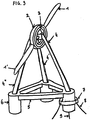
- the nacelle, reference (3) in the figure, is connected to the support arms (4), (4 ') and (4 ") via a pivot here. figure 3 allows to clearly visualize the structural continuity between the upstream support arm, reference (4) in the figure, and the downstream support arms, reference (4 ') and (4 ").
- the rotor, reference (2) in the figure, and its blades, references (1) and (1 ') in the figure is not arranged in cantilever of the nacelle. Therefore, unlike the known wind turbines of the prior art, the nacelle, reference (3) in the figure, does not undergo a strong bending moment therefore the mass of said rotor and said blades. These lower efforts reduce the size of the structure and therefore the cost.
- the nacelle, reference (3) in the figure can rotate relative to the floating structure to adjust the orientation of the surface swept by the blades, references (1) and (1 ') in the figure.
- said swept surface can for example be oriented perfectly in the wind for example through a system of jacks.
- the ratio between the diameter of the hollow axis of the rotor, reference (2) in the figure, and the diameter of the circular surface swept by the blades, references (1) and (1 ') in the figure, is order of 20%.
- the electric generator for example a synchronous generator with wound rotor or permanent magnets in direct contact with said rotor, has a diameter much higher than the generators used by the wind turbines known from the prior art. As known by those skilled in the art, this larger diameter makes it possible to reduce the mass of active material required to obtain a given level of specifications, such as, for example, a nominal torque level of the generator. The cost of said generator is thus reduced.
- the space available inside the nacelle allows to take over large areas the forces due to the generator torque, thrust, gravity and inertia.
- the upper part of the support arm upwind, reference (4) in the figure does not exploit all the available space.
- the local mechanical stresses are lower when the forces are distributed.
- the resistance of the structure to fatigue is thus improved, which reduces the weight and cost of the structure.
- the foot bending moment of said blades is reduced compared to the known wind turbines of the interior art since the free length of said blades is reduced thanks to said large diameter rotor.
- the resistance of said blades to fatigue is thus improved, which reduces the weight and cost of said blades.
- the support arms, references (4), (4 ') and (4 ") on the figure 3 are inclined and have profiled and non-circular sections to reduce aerodynamic disturbances, which is favorable to a better aerodynamic operation of the blades.
- the mast of the wind turbines known from the prior art is systematically vertical and the axis of the rotor supporting the blades is inclined by a few degrees, for example 6 °, in order precisely to provide a sufficient distance between said mat and the blades as they pass in front of said mat. It is easy to understand that the distance between the blades, references (1) and (1 ') on the figure 3 and said support arms are increasing as one moves away from the rotor, which is favorable to a better aerodynamic operation of the blades.
- the outer part of the drum As indicated on the figure 3 , the outer part of the drum, reference (7) in the figure, is in ball joint connection with the structure of the wind turbine.
- the device is particularly suitable for floating wind turbine structures with horizontal axis regardless of the type of float.
- This device is particularly suitable for floating barge floats, SPAR, semi-submersible, or floating platform with a damping pool.
Description
La présente invention concerne une structure pour éolienne flottante.The present invention relates to a floating wind turbine structure.
Plus particulièrement, l'invention se rapporte à un tel support flottant qui comporte des moyens en forme de bras de support, dont la partie supérieure est associée à la nacelle de l'éolienne et dont la partie inférieure est associée à des moyens en forme de flotteur et éventuellement à des moyens formant lest, la masse ajoutée et l'amortissement. Les documents
Cependant on conçoit que de tels moyens en forme de mat de support unique concentrent les contraintes mécaniques en pied de mat et en tête de mat. Ces contraintes étant cycliques à cause des mouvements du flotteur et des variations du vent notamment, on conçoit que le dimensionnement de la structure, en fatigue mécanique notamment, en est affecté.However, it is conceivable that such means in the form of a single support mat concentrate the mechanical stresses at the foot of the mat and at the top of the mat. These constraints being cyclic because of the movements of the float and wind variations in particular, it is conceivable that the dimensioning of the structure, in particular mechanical fatigue, is affected.
On conçoit également que de tels moyens en forme de mat unique sont très proches de la pale ou des pales du rotor lors de leur passage en position verticale avec l'extrémité de la pale pointant vers le sol. Lorsque la ou les pales passent à proximité du mat, on conçoit que la charge aérodynamique sur la ou les pales est brutalement modifiée à cause de perturbations aérodynamiques qui sont d'autant plus grandes que le diamètre du mat est grand et que la distance entre la ou les pales et le mat est petite. On comprend aisément que la variation de ladite charge aérodynamique génère des efforts cycliques, des contraintes mécaniques et une fatigue associée.It is also conceivable that such means in the form of a single mat are very close to the blade or blades of the rotor when they pass in the vertical position with the end of the blade pointing towards the ground. When the blade or blades pass close to the mast, it is conceivable that the aerodynamic load on the blade or blades is abruptly changed because of aerodynamic disturbances which are even larger than the diameter of the mast is large and the distance between the or the blades and the mat is small. It is easily understood that the variation of said aerodynamic load generates cyclic forces, mechanical stresses and associated fatigue.
Le but de l'invention est donc de résoudre ces problèmes en proposant une structure d'éolienne plus légère, plus économique et permettant un meilleur rendement énergétique.The object of the invention is therefore to solve these problems by proposing a wind turbine structure that is lighter, more economical and allows better energy efficiency.
A cet effet, un premier aspect de l'invention a pour objet une structure pour éolienne flottante qui comporte des moyens en forme de plusieurs bras de support de la nacelle, dont la partie supérieure est associée à la nacelle et dont la partie inférieure est associée à des moyens en forme de flotteurs et éventuellement des moyens formant le lest, la masse ajoutée et l'amortissement. Comme connu par l'homme du métier, la nacelle est le moyen permettant d'une part de transformer le couple généré par la ou les pales du rotor actionnée(s) par le vent en débit énergétique de nature le plus souvent électrique ou hydraulique, et d'autre part de maintenir en position le rotor et sa ou ses pales. La structure comporte un bras de support de la nacelle au moins en amont de la nacelle par rapport à la direction du vent. La structure comporte un bras de support de la nacelle au moins en aval de la nacelle par rapport à la direction du vent. Ainsi, la structure permet à un rotor d'éolienne à axe horizontal ou presque horizontal composé d'une ou plusieurs pales de tourner librement autour de l'axe théorique du rotor. En d'autres termes, la structure permet de relier de manière rigide, par exemple de manière soudée et/ou boulonnée, les extrémités supérieures des bras amont et aval sans entraver la rotation du rotor et de sa ou ses pales. Cette liaison peut être réalisée, soit par l'intermédiaire d'au moins une pièce de connexion liée rigidement, soit en fixant directement les extrémités supérieures des bras les unes aux autres. Ainsi, il y a une continuité structurelle entre les bras à leur extrémité supérieure et il n'y a pas de mouvements relatifs entre les bras et ladite au moins une pièce de connexion quand elle est présente.For this purpose, a first aspect of the invention relates to a structure for a floating wind turbine which comprises means in the form of several support arms of the nacelle, the upper part of which is associated with the nacelle and whose lower part is associated with float means and possibly ballast means, added mass and damping. As known to those skilled in the art, the nacelle is the means on the one hand to transform the torque generated by the blade or blades of the rotor (s) driven by the wind energy flow of mostly electric or hydraulic nature, and on the other hand to keep in position the rotor and its blade or blades. The structure comprises a support arm of the nacelle at least upstream of the nacelle with respect to the direction of the wind. The structure comprises a support arm of the nacelle at least downstream of the nacelle with respect to the wind direction. Thus, the structure allows a horizontal or nearly horizontal axis wind turbine rotor consisting of one or more blades to rotate freely about the theoretical axis of the rotor. In other words, the structure makes it possible to rigidly connect, for example in a welded and / or bolted manner, the upper ends of the upstream and downstream arms without hindering the rotation of the rotor and its blade or blades. This connection can be achieved either by means of at least one connecting piece rigidly connected, or by directly fixing the upper ends of the arms to each other. Thus, there is structural continuity between the arms at their upper end and there is no relative movement between the arms and the at least one connecting piece when present.
Ainsi, les fréquences naturelles de résonnance d'une telle structure sont sensiblement plus élevées que celle d'une structure d'éolienne flottante avec un mât fixe et unique, de sorte que les problèmes de vibrations rencontrées sur ces éoliennes sont considérablement réduits. En effet, les fréquences naturelles de résonnance de ces éoliennes avec des mâts en acier sont dans la plage de fréquence d'excitation due à la rotation des pales, ce qui impose d'augmenter par exemple le diamètre du mât pour décaler les fréquences propres de la structure et par conséquent d'augmenter le coût de la structure.Thus, the natural resonance frequencies of such a structure are substantially higher than that of a floating wind turbine structure with a fixed and single mast, so that the vibration problems encountered on these wind turbines are greatly reduced. Indeed, the natural frequencies of resonance of these wind turbines with steel poles are in the excitation frequency range due to the rotation of the blades, which makes it necessary to increase for example the diameter of the mast to shift the eigenfrequencies of structure and therefore increase the cost of the structure.
On comprend aisément que le rotor ne peut plus pivoter selon l'axe vertical entièrement comme le font les éoliennes connues de l'art antérieur. On comprend aisément que la distance minimale entre chacun des bras et la ou les pales lors de leur passage à proximité des bras est augmentée significativement par rapport à un mat unique vertical, et ce d'autant plus que l'inclinaison des bras de support par rapport à la verticale est grande. On comprend aisément que cette distance minimale entre une portion de pale et un bras de support est d'autant plus importante que l'on s'éloigne de l'axe de rotation du rotor, ce qui est favorable aux portions de pale les plus éloignées de l'axe de rotation du rotor qui sont la source majeure de captage de l'énergie du vent et donc la source majeure de production d'énergie. L'inclinaison des bras permet donc d'améliorer le rendement énergétique de l'éolienne. Avantageusement, l'inclinaison des bras par rapport à la verticale est comprise en 5 et 55 degrés, voir encore plus avantageusement entre 10 et 45 degrés.It is easy to understand that the rotor can no longer pivot along the vertical axis entirely as do the wind turbines known from the prior art. It is easily understood that the minimum distance between each of the arms and the blade or blades when they pass close to the arms is significantly increased compared to a single vertical mast, and all the more so that the inclination of the support arms by vertical ratio is great. It is easily understood that this minimum distance between a blade portion and a support arm is all the greater as one moves away from the axis of rotation of the rotor, which is favorable to the most remote blade portions of the axis of rotation of the rotor which are the major source of wind energy harvesting and therefore the major source of energy production. The inclination of the arms therefore improves the energy efficiency of the wind turbine. Advantageously, the inclination of the arms relative to the vertical is between 5 and 55 degrees, see even more advantageously between 10 and 45 degrees.
Selon un autre mode de réalisation, l'axe du rotor portant la ou les pales est un axe creux, ce afin que la nacelle et la partie supérieure des bras de support puissent être reliées ensemble dans ledit axe creux. Le diamètre intérieur dudit axe creux pourra éventuellement être relativement grand par rapport au diamètre extérieur du rotor et de la ou des pales, c'est-à-dire le diamètre décrit par l'extrémité de la plus grande pale. Le rapport entre ces deux diamètres pourra être compris entre deux et cinquante pour cent. Ainsi, la longueur libre de la ou des pales sera réduite pour un même diamètre externe du rotor portant la ou les pales, sans réduction significative du couple aérodynamique puisque les portions de pales proches du centre du rotor ne génèrent pas ou très peu de couple. Comme connu par l'homme du métier, la majeure partie du couple produit par le rotor et sa ou ses pales provient de la moitié de pale la plus éloignée de l'axe de rotation du rotor. Ainsi, la réduction de la longueur de la ou des pales pour un même diamètre total extérieur de l'ensemble rotor-pale(s) engendre une longueur libre des pales plus faibles et donc des contraintes mécaniques en pied de pale plus faibles, ce qui réduit le coût des pales.According to another embodiment, the axis of the rotor carrying the blade or blades is a hollow axis, so that the nacelle and the upper part of the support arms can be connected together in said hollow axis. The inner diameter of said hollow shaft may possibly be relatively large relative to the outer diameter of the rotor and the blade or blades, that is to say the diameter described by the end of the largest blade. The ratio between these two diameters can be between two and fifty to hundred. Thus, the free length of the blade or blades will be reduced for the same outer diameter of the rotor carrying the blade or blades, without significant reduction of the aerodynamic torque since the blade portions near the center of the rotor do not generate or very little torque. As known to those skilled in the art, most of the torque produced by the rotor and its blade or blades comes from the half of the blade farthest from the axis of rotation of the rotor. Thus, the reduction in the length of the blade or blades for the same total external diameter of the rotor-blade unit (s) generates a free length of the weaker blades and therefore lower mechanical stresses at the bottom of the blade. reduces the cost of the blades.
D'autre part, en accroissant le diamètre de l'axe creux, l'espace disponible pour relier les bras à leur extrémité supérieure est agrandi, ce qui a pour effet de pouvoir répartir et diffuser les efforts mécaniques notamment conséquents à la poussée du vent sur les pales dans l'axe du vent. Les contraintes mécaniques dans la structure s'en trouvent ainsi diminuées. Ainsi, la structure est plus facile à mettre en oeuvre.On the other hand, by increasing the diameter of the hollow shaft, the space available to connect the arms at their upper end is enlarged, which has the effect of distributing and spreading the mechanical forces including consistent with the thrust of the wind on the blades in the axis of the wind. The mechanical stresses in the structure are thus reduced. Thus, the structure is easier to implement.
Selon un autre mode de réalisation, les bras de support sont éventuellement carénés ou profilés de manière à réduire les perturbations aérodynamiques sur les pales du rotor et à limiter le fardage. Le profil pourra avoir une forme de profil NACA. De préférence, le coefficient de traînée (Cd) sera inférieur à 0,5, voire inférieur à 0,2. Ce type de profil est inadapté à une éolienne connue de l'art antérieur, car la nacelle s'oriente alors face au vent sans que le mat fixe ne puisse pivoter. Avec une telle éolienne de l'art antérieur, un mat de section profilé ne serait avantageux en termes de traînée aérodynamique que pour une direction unique de vent. Dès que le vent ne serait plus aligné avec la corde de la section profilée du mât, les perturbations aérodynamiques seraient plus importantes qu'avec une section circulaire. C'est pour cette raison que les mats des éoliennes de l'art antérieur sont majoritairement circulaire pour que le rendement soit le même quelle que soit la direction du vent.According to another embodiment, the support arms are optionally shrouded or profiled so as to reduce aerodynamic disturbances on the rotor blades and limit windage. The profile may have a NACA profile form. Preferably, the drag coefficient (Cd) will be less than 0.5, or even less than 0.2. This type of profile is unsuited to a wind turbine known from the prior art, because the nacelle is then facing the wind without the fixed mast can rotate. With such a wind turbine of the prior art, a profiled section mat would be advantageous in terms of aerodynamic drag only for a single direction of wind. As soon as the wind is no longer aligned with the rope of the profiled section of the mast, the aerodynamic disturbances would be greater than a circular section. It is for this reason that the mats of wind turbines of the prior art are mostly circular so that the yield is the same regardless of the direction of the wind.
Selon un autre mode de réalisation, les bras de support de la nacelle peuvent éventuellement être reliés entre eux par des bras de maintien éventuellement horizontaux placés dans la partie inférieure de la structure porteuse. Ainsi les bras de support de la nacelle sont reliés entre eux de manière rigide, d'une part dans leur partie supérieure au niveau de la nacelle, et d'autre part dans leur partie inférieure au-dessus et/ou au-dessous de la surface de l'eau par des bras de maintien. Un tel dispositif permet de rendre la structure plus rigide.According to another embodiment, the support arms of the nacelle may optionally be interconnected by possibly horizontal holding arms placed in the lower part of the carrier structure. Thus the support arms of the nacelle are interconnected rigidly, firstly in their upper part at the nacelle, and secondly in their lower part above and / or below the nacelle. surface of the water by holding arms. Such a device makes the structure more rigid.
Selon un autre mode de réalisation, l'orientation de l'éolienne par rapport à l'axe du vent est réalisée par un ou plusieurs moyens. Le premier moyen consiste en une auto-orientation de l'éolienne par rapport à son ou ses points d'amarrages. Pour cela, le ou les points amarrage des lignes d'ancrages sont placés en amont de la position du centre de poussée vélique par rapport au vent. Il est entendu qu'une ligne d'ancrage est le moyen de relier l'éolienne flottante au fond de la mer ou du lac et que le centre de poussée vélique est le barycentre des efforts horizontaux exercés par le vent sur la ou les pales et les parties émergées de l'éolienne flottante soumises à l'action du vent. Ainsi, l'éolienne s'auto-oriente face au vent de la même manière qu'un navire au mouillage. Le second moyen est réalisé grâce une nacelle orientable qui pivote au sommet des bras de support de la nacelle selon un axe vertical et/ou un axe horizontal perpendiculaire à l'axe de rotation des pales. Bien que limité par la présence des bras de support, le mouvement de rotation de la nacelle selon l'axe vertical permet d'ajuster l'orientation de l'éolienne pour par exemple dévier le sillage aérodynamique ou contrecarrer l'effet d'une houle dont l'orientation serait différente de l'orientation du vent. Ceci permet de garantir le rendement aérodynamique de l'éolienne quelle que soit l'orientation du vent et de la houle. Comme connu par l'homme du métier, le sillage d'une éolienne est caractérisé par une zone aval au vent par rapport à l'éolienne dans laquelle la vitesse moyenne de l'écoulement est plus faible qu'en amont de l'éolienne et la turbulence plus élevée qu'en amont de l'éolienne. Ledit moyen de rotation de la nacelle permettant de dévier le sillage permet donc de déplacer la zone de sillage afin que ladite zone de sillage ne perturbe pas le rendement aérodynamique des éoliennes flottantes ou fixes disposées en aval. Comme connu par l'homme du métier, les éoliennes sont parfois regroupées au sein d'un parc éolien, également appelé ferme éolienne. L'invention peut éventuellement utiliser une nacelle pendulaire, caractérisée par le fait que la nacelle de l'éolienne est reliée à la structure porteuse par une liaison pivot d'axe horizontal et perpendiculaire à l'axe du rotor. Ceci permet d'ajuster l'orientation du rotor et de sa ou ses pales afin que ledit rotor muni de ses pales soit normal au vecteur vent quelle que soit l'inclinaison de l'éolienne flottante soumise à la poussée du vent et aux efforts dus la houle. Ceci permet également de dévier le sillage de l'éolienne afin de ne pas perturber le fonctionnement des éoliennes éventuellement disposées en aval. L'invention peut éventuellement utiliser un rotor conique ou à conicité variable, c'est-à-dire dont les pales du rotor sont orientées ou orientables par rapport à l'axe de rotation du rotor de sorte que les pales balayent une surface conique plutôt qu'un disque. La structure d'éolienne revendiquée est plus adaptée à ce type de rotor conique que les structures classiques qui sont limitées par la distance entre la nacelle et le mat.According to another embodiment, the orientation of the wind turbine with respect to the axis of the wind is carried out by one or more means. The first means consists in a self-orientation of the wind turbine with respect to its mooring point (s). For this, the docking point or points anchor lines are placed upstream of the position of the center of sailing force relative to the wind. It is understood that an anchor line is the means of connecting the floating wind turbine to the bottom of the sea or lake and that the center of buoyancy is the centroid of the horizontal forces exerted by the wind on the blade or blades and the emergent parts of the floating wind turbine subjected to the action of the wind. Thus, the wind turbine is self-oriented facing the wind in the same way as a ship at anchor. The second means is achieved through an orientable nacelle which pivots at the top of the support arms of the nacelle along a vertical axis and / or a horizontal axis perpendicular to the axis of rotation of the blades. Although limited by the presence of the support arms, the rotational movement of the nacelle along the vertical axis makes it possible to adjust the orientation of the wind turbine to, for example, deflect the wake aerodynamic or counteract the effect of a swell whose orientation would be different from the orientation of the wind. This makes it possible to guarantee the aerodynamic efficiency of the wind turbine whatever the orientation of the wind and the swell. As known to those skilled in the art, the wake of a wind turbine is characterized by a downwind zone with respect to the wind turbine in which the average speed of the flow is lower than upstream of the wind turbine and turbulence higher than upstream of the wind turbine. Said means of rotation of the nacelle for diverting the wake therefore allows the wake area to be moved so that the said wake zone does not disturb the aerodynamic efficiency of the floating or fixed wind turbines arranged downstream. As known by those skilled in the art, wind turbines are sometimes grouped together in a wind farm, also called a wind farm. The invention may optionally use a pendular platform, characterized in that the nacelle of the wind turbine is connected to the carrier structure by a pivot connection of horizontal axis and perpendicular to the axis of the rotor. This makes it possible to adjust the orientation of the rotor and its blade or blades so that said rotor provided with its blades is normal to the wind vector regardless of the inclination of the floating wind turbine subjected to the thrust of the wind and the forces due to it. the swell. This also allows to divert the wake of the wind turbine so as not to disturb the operation of wind turbines possibly disposed downstream. The invention may optionally use a conical rotor or variable conicity, that is to say, whose rotor blades are oriented or orientable relative to the axis of rotation of the rotor so that the blades sweep a conical surface rather than a disc. The claimed wind turbine structure is more suited to this type of conical rotor than conventional structures which are limited by the distance between the nacelle and the mast.
Selon un autre mode de réalisation, la structure d'éolienne comprend un ou des points d'amarrages de une ou des lignes d'ancrages situés sur la partie externe d'un touret composé de deux pièces concentriques au moins, les deux pièces formant cinématiquement au moins un pivot d'axe de rotation vertical, la pièce interne du touret étant solidaire de la structure flottante de l'éolienne et étant évidée en son centre le long de l'axe vertical de rotation entre lesdites deux pièces.
La structure d'éolienne comprend un ombilic, élément comprenant les câbles électriques de transmission de puissance et les câbles de transmission de données et de commande, qui passe par la partie évidée du touret solidaire de la structure de l'éolienne. Ainsi, l'ombilic n'est pas en contact avec les lignes ancrages quelle que soit l'orientation de l'éolienne par rapport au fond de la mer.
En d'autres termes, la structure d'éolienne flottante est agencée pour être amarrée par l'intermédiaire d'au moins un point d'amarrage et comprend :
- un touret évidé traversant agencé pour former au moins un pivot d'axe de rotation vertical de sorte à permettre le pivotement de ladite structure d'éolienne par rapport audits points d'amarrage,
- un ombilic
The wind turbine structure comprises an umbilicus, an element comprising the electric power transmission cables and the data transmission and control cables, which passes through the recessed portion of the drum integral with the structure of the wind turbine. Thus, the umbilicus is not in contact with anchor lines regardless of the orientation of the wind turbine relative to the seabed.
In other words, the floating wind turbine structure is arranged to be moored via at least one mooring point and comprises:
- a hollow recessed drum arranged to form at least one vertical axis of rotation pivot so as to allow the pivoting of said wind turbine structure with respect to said mooring points,
- an umbilicus
Un dernier aspect de l'invention consiste en une éolienne flottante comportant :
- un support flottant,
- un rotor muni d'au moins une pale agencée pour tourner sous l'effet du vent dans un plan sensiblement normal à l'axe du vent, ledit plan définissant une zone éolienne au vent et une zone éolienne sous le vent,
- une nacelle agencée pour transformer la rotation du vent en débit énergétique,
- un portique agencé pour supporter le rotor, le dit portique comportant au moins un premier bras et au moins un deuxième bras, fixes par rapport au flotteur et reliés l'un à l'autre de manière rigide,
- a floating support,
- a rotor provided with at least one blade arranged to rotate under the effect of the wind in a plane substantially normal to the axis of the wind, said plane defining a windy zone in the wind and a wind zone in the wind,
- a nacelle arranged to transform the rotation of the wind into energy flow,
- a gantry arranged to support the rotor, said gantry having at least a first arm and at least a second arm, fixed with respect to the float and rigidly connected to each other,
Les principaux avantages de cette invention sont :
- l'augmentation de la distance pale-bras et donc la réduction des efforts cycliques et de la fatigue mécanique sur la ou les pales.
- la réduction des perturbations aérodynamiques générées par l'habituel mat de support de la nacelle et par conséquent la réduction des efforts cycliques et de la fatigue mécanique sur la ou les pales, ladite réduction étant due d'une part aux diamètres faibles des bras de support par rapport au diamètre plus grand d'un mat unique et d'autre part à la forme aérodynamique des bras de support, forme rendue possible par le fait que l'ensemble de la structure de l'éolienne s'oriente face au vent, ce qui n'est pas le cas d'une éolienne dont seule la nacelle s'oriente face au vent, le mat fixe devant être conçu pour toutes les orientations possibles du vent.
- la réduction des concentrations de contraintes dans la structure de l'éolienne flottante, rendue possible d'une part par la multiplication des bras de supports de la nacelle et leur positionnement et d'autre part par le grand espace disponible à l'intérieur de l'axe creux du rotor qui peut être utilisé pour répartir et diffuser les efforts à la jonction supérieure des bras de supports et de la nacelle, ainsi que par la liaison rigide des bras entre eux.
- l'augmentation des fréquences propres de la structure par rapport aux structures connues de l'art antérieur, ce qui permet de ne pas surdimensionner la structure pour décaler lesdites fréquences propres et ainsi garantir que la structure n'entre en résonnance avec l'excitation due au rotor.
- la réduction de la longueur de la ou des pales pour un même diamètre total extérieur de l'ensemble rotor-pale(s), ce qui se traduit par une longueur libre des pales plus faibles et donc des contraintes mécaniques en pied de pale plus faibles.
- the increase of the blade-arm distance and therefore the reduction of cyclic forces and mechanical fatigue on the blade or blades.
- the reduction of aerodynamic disturbances generated by the usual support mat of the nacelle and consequently the reduction of cyclic forces and mechanical fatigue on the blade or blades, said reduction being due on the one hand to the small diameters of the support arms compared to the larger diameter of a single mast and the aerodynamic shape of the support arms, made possible by the fact that the entire structure of the wind turbine is facing the wind, this which is not the case of a wind turbine of which only the nacelle is oriented towards the wind, the fixed mast having to be conceived for all the possible orientations of the wind.
- the reduction of the stress concentrations in the structure of the floating wind turbine, made possible on the one hand by the multiplication of the support arms of the nacelle and their positioning and on the other hand by the large space available inside the hollow shaft of the rotor which can be used to distribute and diffuse forces at the upper junction of the arms of supports and the nacelle, as well as by the rigid connection of the arms between them.
- the increase of eigenfrequencies of the structure with respect to known structures of the prior art, which makes it possible not to oversize the structure to shift said eigenfrequencies and thus to ensure that the structure does not resonate with the excitation due to the rotor.
- the reduction of the length of the blade or blades for the same total external diameter of the rotor-blade unit (s), which results in a free length of the weaker blades and therefore lower mechanical stresses at the blade root .
L'invention sera mieux comprise avec les exemples qui vont suivre et donnés uniquement à titre d'exemples. Les dessins annexés illustrent l'invention.
- La
figure 1 représente de manière schématique en trois dimensions le dispositif selon l'invention. - La
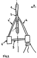
figure 2 représente de manière schématique une vue de profil du dispositif selon l'invention. - La
figure 3 représente de manière schématique en trois dimensions le dispositif selon l'invention.
- The
figure 1 schematically shows in three dimensions the device according to the invention. - The
figure 2 schematically represents a side view of the device according to the invention. - The
figure 3 schematically shows in three dimensions the device according to the invention.
Comme indiqué sur la
Comme indiqué sur la
Comme indiqué sur la
Comme indiqué sur la
Comme indiqué sur la
Comme indiqué sur la
Comme indiqué sur la
Comme indiqué sur la
Le dispositif est particulièrement adapté pour les structures d'éoliennes flottantes à axe horizontal quelle que soit le type de flotteur. Ce dispositif est particulièrement adapté pour des flotteurs de type barge flottante, SPAR, semi-submersible, ou plate-forme flottante dotée d'une piscine amortissante.The device is particularly suitable for floating wind turbine structures with horizontal axis regardless of the type of float. This device is particularly suitable for floating barge floats, SPAR, semi-submersible, or floating platform with a damping pool.
Claims (6)
- Floating wind turbine structure comprising- a rotor (2) bearing at least one blade (1),- at least two support arms (4) (4') of a nacelle (3), said at least two support arms comprising upper and lower parts, said upper parts are associated with the nacelle (3) and said lower parts are associated with means in the form of floats (6),- at least one support arm (4) located upstream of the rotor (2) relative to the wind direction,- at least one support arm (4') located downstream of the rotor (2) relative to the wind direction,
characterised in that the rotor (2) is provided with a hollow spindle arranged to rotate around the nacelle (3). - Floating wind turbine structure as claimed in claim 1, characterised in that said upper parts of the support arms (4) (4') are connected together.
- Floating wind turbine structure as claimed in any one of the preceding claims, comprising at least one mooring point, characterised in that said at least one mooring point is located upstream of the centre of sail force relative to the wind direction.
- Floating wind turbine structure as claimed in any one of the preceding claims, characterised in that at least one support arm (4) is streamlined or profiled so as to limit the aerodynamic disturbances on the blade(s) (1) of the wind turbine.
- Floating wind turbine structure as claimed in any one of the preceding claims, the hollow spindle of the rotor (2) having a bore of revolution, characterised in that the ratio between the diameter of the bore and the maximum outer diameter defined by the end of said at least one blade (1) upon rotation of the rotor about the nacelle (3) is between two and fifty percent.
- Floating wind turbine structure as claimed in any one of the preceding claims arranged to be moored via at least one mooring point and comprising:- a through-going recessed reel arranged to form at least one pivot with a vertical rotational axis so as to allow the pivoting of said wind turbine structure relative to said mooring points,- an umbilical (9),
characterised in that the umbilical passes into the recess of said reel.
Applications Claiming Priority (2)
| Application Number | Priority Date | Filing Date | Title |
|---|---|---|---|
| FR1300926A FR3004764B1 (en) | 2013-04-18 | 2013-04-18 | STRUCTURE FOR FLOATING WIND TURBINES |
| PCT/EP2014/001037 WO2014170027A1 (en) | 2013-04-18 | 2014-04-17 | Floating wind turbine structure |
Publications (2)
| Publication Number | Publication Date |
|---|---|
| EP2986848A1 EP2986848A1 (en) | 2016-02-24 |
| EP2986848B1 true EP2986848B1 (en) | 2018-07-04 |
Family
ID=49322413
Family Applications (1)
| Application Number | Title | Priority Date | Filing Date |
|---|---|---|---|
| EP14725000.5A Active EP2986848B1 (en) | 2013-04-18 | 2014-04-17 | Floating wind turbine structure |
Country Status (6)
| Country | Link |
|---|---|
| US (1) | US9976540B2 (en) |
| EP (1) | EP2986848B1 (en) |
| JP (1) | JP6396427B2 (en) |
| KR (1) | KR102225643B1 (en) |
| FR (2) | FR3004764B1 (en) |
| WO (1) | WO2014170027A1 (en) |
Families Citing this family (15)
| Publication number | Priority date | Publication date | Assignee | Title |
|---|---|---|---|---|
| NO20111329A1 (en) * | 2011-09-29 | 2012-10-08 | Windel As | Floating wind turbine |
| US9308975B2 (en) * | 2013-12-30 | 2016-04-12 | Google Inc. | Spar buoy platform |
| ES2694449B2 (en) | 2017-06-20 | 2020-06-02 | Exponential Renewables S L | FLOATING STRUCTURE FOR MARINE WIND TURBINE |
| SE542925C2 (en) * | 2018-01-19 | 2020-09-15 | Freia Offshore Ab | Floating wind power platform |
| WO2019143283A1 (en) * | 2018-01-19 | 2019-07-25 | Freia Offshore Ab | Floating wind power platform with tension leg device |
| FR3086352B1 (en) * | 2018-09-20 | 2020-09-11 | Eolink | FLOATING WIND TURBINE WITH PILOTABLE LACE POSITION |
| FR3086351A1 (en) | 2018-09-20 | 2020-03-27 | Eolink | FLOATING DYNAMIC WIND TURBINE IN STABLE LACE |
| WO2020109674A1 (en) | 2018-11-30 | 2020-06-04 | Asah Lm | Multi-generator electrical power generation assembly for high-power floating wind turbines |
| EP3902995A4 (en) * | 2019-02-15 | 2022-09-14 | Northeastern University | Shallow draft, wide-base floating wind turbine without nacelle |
| EP4153473B1 (en) * | 2020-05-22 | 2024-03-13 | Encomara Limited | Disconnectable mooring system |
| WO2021255509A1 (en) * | 2020-06-19 | 2021-12-23 | Zhiyong Yang | A floating platform with canted columns |
| GB2598615A (en) | 2020-09-04 | 2022-03-09 | Ebtec As | Floating support arrangement |
| NO346590B1 (en) | 2020-09-18 | 2022-10-17 | Fred Olsen Ocean Ltd | Wind turbine with floating foundation |
| WO2023173100A1 (en) * | 2022-03-11 | 2023-09-14 | Sofec, Inc. | Offshore wind turbine systems and processes for installing same |
| CN117231425B (en) * | 2023-11-13 | 2024-02-06 | 中国海洋大学 | Wake flow control system and method of floating fan based on forward inclination of platform |
Family Cites Families (9)
| Publication number | Priority date | Publication date | Assignee | Title |
|---|---|---|---|---|
| DE19851735A1 (en) * | 1998-11-10 | 2000-05-11 | Friedrich Hensberg | Wind driven floating power generating unit comprises rotor blades which are strengthened by tensioning cables with streamlined cross sections |
| AU2001242321A1 (en) * | 2000-03-28 | 2001-10-08 | Per Lauritsen | Floating offshore wind power installation |
| NO324756B1 (en) * | 2003-04-28 | 2007-12-10 | Sway As | Liquid wind turbine with stiffening system |
| US8668455B2 (en) * | 2009-07-02 | 2014-03-11 | Alfred Finnell | Turbine wheel |
| KR101116672B1 (en) * | 2009-07-07 | 2012-03-14 | 원인호 | Offshore Wind Power System |
| US8197208B2 (en) * | 2009-12-16 | 2012-06-12 | Clear Path Energy, Llc | Floating underwater support structure |
| US9270150B2 (en) * | 2009-12-16 | 2016-02-23 | Clear Path Energy, Llc | Axial gap rotating electrical machine |
| DE202010003654U1 (en) * | 2010-03-16 | 2011-07-25 | Christian Hestermann | Offshore wind power raft |
| WO2012150623A1 (en) * | 2011-05-02 | 2012-11-08 | E&E株式会社 | Horizontal axis wind power generator |
-
2013
- 2013-04-18 FR FR1300926A patent/FR3004764B1/en not_active Expired - Fee Related
-
2014
- 2014-04-17 US US14/783,933 patent/US9976540B2/en active Active
- 2014-04-17 KR KR1020157029164A patent/KR102225643B1/en active IP Right Grant
- 2014-04-17 EP EP14725000.5A patent/EP2986848B1/en active Active
- 2014-04-17 JP JP2016508043A patent/JP6396427B2/en active Active
- 2014-04-17 WO PCT/EP2014/001037 patent/WO2014170027A1/en active Application Filing
- 2014-04-18 FR FR1400946A patent/FR3004765B1/en not_active Expired - Fee Related
Non-Patent Citations (1)
| Title |
|---|
| None * |
Also Published As
| Publication number | Publication date |
|---|---|
| KR20160008167A (en) | 2016-01-21 |
| FR3004764B1 (en) | 2017-01-13 |
| US20160061192A1 (en) | 2016-03-03 |
| JP6396427B2 (en) | 2018-09-26 |
| US9976540B2 (en) | 2018-05-22 |
| WO2014170027A1 (en) | 2014-10-23 |
| FR3004765B1 (en) | 2018-05-04 |
| KR102225643B1 (en) | 2021-03-08 |
| FR3004764A1 (en) | 2014-10-24 |
| EP2986848A1 (en) | 2016-02-24 |
| FR3004765A1 (en) | 2014-10-24 |
| JP2016515680A (en) | 2016-05-30 |
Similar Documents
| Publication | Publication Date | Title |
|---|---|---|
| EP2986848B1 (en) | Floating wind turbine structure | |
| EP1718863B1 (en) | Hydraulic turbomachine | |
| CA3015708C (en) | Floating wind turbine having twin vertical axis turbines with improved efficiency | |
| EP2620635B1 (en) | Blade for a rotor of a marine turbine, rotor of a marine turbine including such a blade, associated marine turbine and method for manufacturing such a blade | |
| EP2906818B1 (en) | Wind turbine on a spar floating structure with two rotors on a v-shaped support structure | |
| EP3853118B1 (en) | Floating wind turbine with controllable yaw position | |
| EP2620634B1 (en) | Rotor of a marine turbine comprising at least one blade rotatably mobile about a radial axis, and means for limiting the rotational movement of said blade, and marine turbine including such a rotor | |
| WO2008068390A1 (en) | Wave energy recovery device | |
| WO2010109081A1 (en) | Rotor for a power generator, in particular for wind turbines | |
| FR2984420A1 (en) | WIND TURBINE MOUNTED ON A ROTATING PLATFORM | |
| FR3086351A1 (en) | FLOATING DYNAMIC WIND TURBINE IN STABLE LACE | |
| WO2015055962A1 (en) | Compact floating hydroelectric plant | |
| FR2938305A1 (en) | AEROGENERATOR BIROTOR "IN V" BIPALS HAS OSCILLATING HUBS ON STRUCTURE LESTEE FLOTTANT TENDU | |
| FR2922273A1 (en) | Rotor for electric power generation device, has semi-conical blades obliquely oriented with respect to rotational axis, and modification unit modifying obliquity of blades, where blades are connected to shaft by connections | |
| FR3054268A1 (en) | PALLET FOR MOUNTING ON A WIND TURBINE COMPRISING A TURNING SAIL AROUND A BEAM SLIDED INSIDE. | |
| FR3087229A1 (en) | VERTICAL AXIS TURBINE | |
| FR3089491A1 (en) | Wind turbine, in particular a floating wind turbine having improved stability. | |
| FR2855563A1 (en) | Wind turbine, has median fairing centered on rotating axis of blades and defining convergent/divergent external static diffuser to concentrate air flow by end of blades | |
| WO2017046330A1 (en) | Vertical-axis wind turbine and methods for assembly and disassembly |
Legal Events
| Date | Code | Title | Description |
|---|---|---|---|
| PUAI | Public reference made under article 153(3) epc to a published international application that has entered the european phase |
Free format text: ORIGINAL CODE: 0009012 |
|
| 17P | Request for examination filed |
Effective date: 20151117 |
|
| AK | Designated contracting states |
Kind code of ref document: A1 Designated state(s): AL AT BE BG CH CY CZ DE DK EE ES FI FR GB GR HR HU IE IS IT LI LT LU LV MC MK MT NL NO PL PT RO RS SE SI SK SM TR |
|
| AX | Request for extension of the european patent |
Extension state: BA ME |
|
| DAX | Request for extension of the european patent (deleted) | ||
| GRAP | Despatch of communication of intention to grant a patent |
Free format text: ORIGINAL CODE: EPIDOSNIGR1 |
|
| STAA | Information on the status of an ep patent application or granted ep patent |
Free format text: STATUS: GRANT OF PATENT IS INTENDED |
|
| INTG | Intention to grant announced |
Effective date: 20161222 |
|
| GRAJ | Information related to disapproval of communication of intention to grant by the applicant or resumption of examination proceedings by the epo deleted |
Free format text: ORIGINAL CODE: EPIDOSDIGR1 |
|
| STAA | Information on the status of an ep patent application or granted ep patent |
Free format text: STATUS: REQUEST FOR EXAMINATION WAS MADE |
|
| INTC | Intention to grant announced (deleted) | ||
| GRAP | Despatch of communication of intention to grant a patent |
Free format text: ORIGINAL CODE: EPIDOSNIGR1 |
|
| STAA | Information on the status of an ep patent application or granted ep patent |
Free format text: STATUS: GRANT OF PATENT IS INTENDED |
|
| INTG | Intention to grant announced |
Effective date: 20171027 |
|
| GRAS | Grant fee paid |
Free format text: ORIGINAL CODE: EPIDOSNIGR3 |
|
| GRAA | (expected) grant |
Free format text: ORIGINAL CODE: 0009210 |
|
| STAA | Information on the status of an ep patent application or granted ep patent |
Free format text: STATUS: THE PATENT HAS BEEN GRANTED |
|
| AK | Designated contracting states |
Kind code of ref document: B1 Designated state(s): AL AT BE BG CH CY CZ DE DK EE ES FI FR GB GR HR HU IE IS IT LI LT LU LV MC MK MT NL NO PL PT RO RS SE SI SK SM TR |
|
| REG | Reference to a national code |
Ref country code: GB Ref legal event code: FG4D Free format text: NOT ENGLISH |
|
| REG | Reference to a national code |
Ref country code: CH Ref legal event code: EP |
|
| REG | Reference to a national code |
Ref country code: AT Ref legal event code: REF Ref document number: 1014795 Country of ref document: AT Kind code of ref document: T Effective date: 20180715 |
|
| REG | Reference to a national code |
Ref country code: IE Ref legal event code: FG4D Free format text: LANGUAGE OF EP DOCUMENT: FRENCH |
|
| REG | Reference to a national code |
Ref country code: DE Ref legal event code: R096 Ref document number: 602014027853 Country of ref document: DE |
|
| REG | Reference to a national code |
Ref country code: NL Ref legal event code: MP Effective date: 20180704 |
|
| REG | Reference to a national code |
Ref country code: LT Ref legal event code: MG4D |
|
| REG | Reference to a national code |
Ref country code: AT Ref legal event code: MK05 Ref document number: 1014795 Country of ref document: AT Kind code of ref document: T Effective date: 20180704 |
|
| PG25 | Lapsed in a contracting state [announced via postgrant information from national office to epo] |
Ref country code: NL Free format text: LAPSE BECAUSE OF FAILURE TO SUBMIT A TRANSLATION OF THE DESCRIPTION OR TO PAY THE FEE WITHIN THE PRESCRIBED TIME-LIMIT Effective date: 20180704 |
|
| PG25 | Lapsed in a contracting state [announced via postgrant information from national office to epo] |
Ref country code: CZ Free format text: LAPSE BECAUSE OF FAILURE TO SUBMIT A TRANSLATION OF THE DESCRIPTION OR TO PAY THE FEE WITHIN THE PRESCRIBED TIME-LIMIT Effective date: 20180704 Ref country code: FI Free format text: LAPSE BECAUSE OF FAILURE TO SUBMIT A TRANSLATION OF THE DESCRIPTION OR TO PAY THE FEE WITHIN THE PRESCRIBED TIME-LIMIT Effective date: 20180704 Ref country code: NO Free format text: LAPSE BECAUSE OF FAILURE TO SUBMIT A TRANSLATION OF THE DESCRIPTION OR TO PAY THE FEE WITHIN THE PRESCRIBED TIME-LIMIT Effective date: 20181004 Ref country code: GR Free format text: LAPSE BECAUSE OF FAILURE TO SUBMIT A TRANSLATION OF THE DESCRIPTION OR TO PAY THE FEE WITHIN THE PRESCRIBED TIME-LIMIT Effective date: 20181005 Ref country code: AT Free format text: LAPSE BECAUSE OF FAILURE TO SUBMIT A TRANSLATION OF THE DESCRIPTION OR TO PAY THE FEE WITHIN THE PRESCRIBED TIME-LIMIT Effective date: 20180704 Ref country code: IS Free format text: LAPSE BECAUSE OF FAILURE TO SUBMIT A TRANSLATION OF THE DESCRIPTION OR TO PAY THE FEE WITHIN THE PRESCRIBED TIME-LIMIT Effective date: 20181104 Ref country code: RS Free format text: LAPSE BECAUSE OF FAILURE TO SUBMIT A TRANSLATION OF THE DESCRIPTION OR TO PAY THE FEE WITHIN THE PRESCRIBED TIME-LIMIT Effective date: 20180704 Ref country code: PL Free format text: LAPSE BECAUSE OF FAILURE TO SUBMIT A TRANSLATION OF THE DESCRIPTION OR TO PAY THE FEE WITHIN THE PRESCRIBED TIME-LIMIT Effective date: 20180704 Ref country code: SE Free format text: LAPSE BECAUSE OF FAILURE TO SUBMIT A TRANSLATION OF THE DESCRIPTION OR TO PAY THE FEE WITHIN THE PRESCRIBED TIME-LIMIT Effective date: 20180704 Ref country code: BG Free format text: LAPSE BECAUSE OF FAILURE TO SUBMIT A TRANSLATION OF THE DESCRIPTION OR TO PAY THE FEE WITHIN THE PRESCRIBED TIME-LIMIT Effective date: 20181004 Ref country code: LT Free format text: LAPSE BECAUSE OF FAILURE TO SUBMIT A TRANSLATION OF THE DESCRIPTION OR TO PAY THE FEE WITHIN THE PRESCRIBED TIME-LIMIT Effective date: 20180704 |
|
| PG25 | Lapsed in a contracting state [announced via postgrant information from national office to epo] |
Ref country code: AL Free format text: LAPSE BECAUSE OF FAILURE TO SUBMIT A TRANSLATION OF THE DESCRIPTION OR TO PAY THE FEE WITHIN THE PRESCRIBED TIME-LIMIT Effective date: 20180704 Ref country code: HR Free format text: LAPSE BECAUSE OF FAILURE TO SUBMIT A TRANSLATION OF THE DESCRIPTION OR TO PAY THE FEE WITHIN THE PRESCRIBED TIME-LIMIT Effective date: 20180704 Ref country code: LV Free format text: LAPSE BECAUSE OF FAILURE TO SUBMIT A TRANSLATION OF THE DESCRIPTION OR TO PAY THE FEE WITHIN THE PRESCRIBED TIME-LIMIT Effective date: 20180704 Ref country code: ES Free format text: LAPSE BECAUSE OF FAILURE TO SUBMIT A TRANSLATION OF THE DESCRIPTION OR TO PAY THE FEE WITHIN THE PRESCRIBED TIME-LIMIT Effective date: 20180704 |
|
| REG | Reference to a national code |
Ref country code: DE Ref legal event code: R097 Ref document number: 602014027853 Country of ref document: DE |
|
| PG25 | Lapsed in a contracting state [announced via postgrant information from national office to epo] |
Ref country code: RO Free format text: LAPSE BECAUSE OF FAILURE TO SUBMIT A TRANSLATION OF THE DESCRIPTION OR TO PAY THE FEE WITHIN THE PRESCRIBED TIME-LIMIT Effective date: 20180704 Ref country code: IT Free format text: LAPSE BECAUSE OF FAILURE TO SUBMIT A TRANSLATION OF THE DESCRIPTION OR TO PAY THE FEE WITHIN THE PRESCRIBED TIME-LIMIT Effective date: 20180704 Ref country code: EE Free format text: LAPSE BECAUSE OF FAILURE TO SUBMIT A TRANSLATION OF THE DESCRIPTION OR TO PAY THE FEE WITHIN THE PRESCRIBED TIME-LIMIT Effective date: 20180704 |
|
| PLBE | No opposition filed within time limit |
Free format text: ORIGINAL CODE: 0009261 |
|
| STAA | Information on the status of an ep patent application or granted ep patent |
Free format text: STATUS: NO OPPOSITION FILED WITHIN TIME LIMIT |
|
| PG25 | Lapsed in a contracting state [announced via postgrant information from national office to epo] |
Ref country code: SM Free format text: LAPSE BECAUSE OF FAILURE TO SUBMIT A TRANSLATION OF THE DESCRIPTION OR TO PAY THE FEE WITHIN THE PRESCRIBED TIME-LIMIT Effective date: 20180704 Ref country code: DK Free format text: LAPSE BECAUSE OF FAILURE TO SUBMIT A TRANSLATION OF THE DESCRIPTION OR TO PAY THE FEE WITHIN THE PRESCRIBED TIME-LIMIT Effective date: 20180704 Ref country code: SK Free format text: LAPSE BECAUSE OF FAILURE TO SUBMIT A TRANSLATION OF THE DESCRIPTION OR TO PAY THE FEE WITHIN THE PRESCRIBED TIME-LIMIT Effective date: 20180704 |
|
| 26N | No opposition filed |
Effective date: 20190405 |
|
| REG | Reference to a national code |
Ref country code: NO Ref legal event code: MMEP |
|
| PG25 | Lapsed in a contracting state [announced via postgrant information from national office to epo] |
Ref country code: SI Free format text: LAPSE BECAUSE OF FAILURE TO SUBMIT A TRANSLATION OF THE DESCRIPTION OR TO PAY THE FEE WITHIN THE PRESCRIBED TIME-LIMIT Effective date: 20180704 |
|
| PG25 | Lapsed in a contracting state [announced via postgrant information from national office to epo] |
Ref country code: NO Free format text: LAPSE BECAUSE OF FAILURE TO SUBMIT A TRANSLATION OF THE DESCRIPTION OR TO PAY THE FEE WITHIN THE PRESCRIBED TIME-LIMIT Effective date: 20180704 |
|
| PGFP | Annual fee paid to national office [announced via postgrant information from national office to epo] |
Ref country code: NO Payment date: 20190214 Year of fee payment: 6 |
|
| REG | Reference to a national code |
Ref country code: DE Ref legal event code: R119 Ref document number: 602014027853 Country of ref document: DE |
|
| REG | Reference to a national code |
Ref country code: CH Ref legal event code: PL |
|
| REG | Reference to a national code |
Ref country code: BE Ref legal event code: MM Effective date: 20190430 |
|
| PG25 | Lapsed in a contracting state [announced via postgrant information from national office to epo] |
Ref country code: MC Free format text: LAPSE BECAUSE OF FAILURE TO SUBMIT A TRANSLATION OF THE DESCRIPTION OR TO PAY THE FEE WITHIN THE PRESCRIBED TIME-LIMIT Effective date: 20180704 Ref country code: LU Free format text: LAPSE BECAUSE OF NON-PAYMENT OF DUE FEES Effective date: 20190417 |
|
| PG25 | Lapsed in a contracting state [announced via postgrant information from national office to epo] |
Ref country code: CH Free format text: LAPSE BECAUSE OF NON-PAYMENT OF DUE FEES Effective date: 20190430 Ref country code: LI Free format text: LAPSE BECAUSE OF NON-PAYMENT OF DUE FEES Effective date: 20190430 Ref country code: DE Free format text: LAPSE BECAUSE OF NON-PAYMENT OF DUE FEES Effective date: 20191101 |
|
| PG25 | Lapsed in a contracting state [announced via postgrant information from national office to epo] |
Ref country code: BE Free format text: LAPSE BECAUSE OF NON-PAYMENT OF DUE FEES Effective date: 20190430 |
|
| PG25 | Lapsed in a contracting state [announced via postgrant information from national office to epo] |
Ref country code: TR Free format text: LAPSE BECAUSE OF FAILURE TO SUBMIT A TRANSLATION OF THE DESCRIPTION OR TO PAY THE FEE WITHIN THE PRESCRIBED TIME-LIMIT Effective date: 20180704 |
|
| PG25 | Lapsed in a contracting state [announced via postgrant information from national office to epo] |
Ref country code: PT Free format text: LAPSE BECAUSE OF FAILURE TO SUBMIT A TRANSLATION OF THE DESCRIPTION OR TO PAY THE FEE WITHIN THE PRESCRIBED TIME-LIMIT Effective date: 20181104 |
|
| PG25 | Lapsed in a contracting state [announced via postgrant information from national office to epo] |
Ref country code: CY Free format text: LAPSE BECAUSE OF FAILURE TO SUBMIT A TRANSLATION OF THE DESCRIPTION OR TO PAY THE FEE WITHIN THE PRESCRIBED TIME-LIMIT Effective date: 20180704 |
|
| PG25 | Lapsed in a contracting state [announced via postgrant information from national office to epo] |
Ref country code: HU Free format text: LAPSE BECAUSE OF FAILURE TO SUBMIT A TRANSLATION OF THE DESCRIPTION OR TO PAY THE FEE WITHIN THE PRESCRIBED TIME-LIMIT; INVALID AB INITIO Effective date: 20140417 Ref country code: MT Free format text: LAPSE BECAUSE OF FAILURE TO SUBMIT A TRANSLATION OF THE DESCRIPTION OR TO PAY THE FEE WITHIN THE PRESCRIBED TIME-LIMIT Effective date: 20180704 |
|
| REG | Reference to a national code |
Ref country code: GB Ref legal event code: 732E Free format text: REGISTERED BETWEEN 20220106 AND 20220112 |
|
| PG25 | Lapsed in a contracting state [announced via postgrant information from national office to epo] |
Ref country code: MK Free format text: LAPSE BECAUSE OF FAILURE TO SUBMIT A TRANSLATION OF THE DESCRIPTION OR TO PAY THE FEE WITHIN THE PRESCRIBED TIME-LIMIT Effective date: 20180704 |
|
| P01 | Opt-out of the competence of the unified patent court (upc) registered |
Effective date: 20230526 |
|
| PGFP | Annual fee paid to national office [announced via postgrant information from national office to epo] |
Ref country code: IE Payment date: 20230425 Year of fee payment: 10 Ref country code: FR Payment date: 20230427 Year of fee payment: 10 |
|
| PGFP | Annual fee paid to national office [announced via postgrant information from national office to epo] |
Ref country code: GB Payment date: 20230428 Year of fee payment: 10 |