EP2985573B1 - Appareil et procédé de fixation d'un dispositif électronique - Google Patents
Appareil et procédé de fixation d'un dispositif électronique Download PDFInfo
- Publication number
- EP2985573B1 EP2985573B1 EP14180836.0A EP14180836A EP2985573B1 EP 2985573 B1 EP2985573 B1 EP 2985573B1 EP 14180836 A EP14180836 A EP 14180836A EP 2985573 B1 EP2985573 B1 EP 2985573B1
- Authority
- EP
- European Patent Office
- Prior art keywords
- fastening
- locking
- mounting base
- slider
- fixing
- Prior art date
- Legal status (The legal status is an assumption and is not a legal conclusion. Google has not performed a legal analysis and makes no representation as to the accuracy of the status listed.)
- Active
Links
- 238000000034 method Methods 0.000 title claims description 10
- 230000000903 blocking effect Effects 0.000 claims description 7
- 238000006073 displacement reaction Methods 0.000 claims description 4
- 239000002981 blocking agent Substances 0.000 description 6
- 230000035939 shock Effects 0.000 description 5
- 229910000831 Steel Inorganic materials 0.000 description 2
- 238000003780 insertion Methods 0.000 description 2
- 230000037431 insertion Effects 0.000 description 2
- 125000006850 spacer group Chemical group 0.000 description 2
- 229910001220 stainless steel Inorganic materials 0.000 description 2
- 239000010935 stainless steel Substances 0.000 description 2
- 239000010959 steel Substances 0.000 description 2
- 238000012790 confirmation Methods 0.000 description 1
- 239000000834 fixative Substances 0.000 description 1
- 230000001939 inductive effect Effects 0.000 description 1
- 238000001746 injection moulding Methods 0.000 description 1
- 238000004519 manufacturing process Methods 0.000 description 1
- 230000003287 optical effect Effects 0.000 description 1
Images


Classifications
-
- G—PHYSICS
- G01—MEASURING; TESTING
- G01D—MEASURING NOT SPECIALLY ADAPTED FOR A SPECIFIC VARIABLE; ARRANGEMENTS FOR MEASURING TWO OR MORE VARIABLES NOT COVERED IN A SINGLE OTHER SUBCLASS; TARIFF METERING APPARATUS; MEASURING OR TESTING NOT OTHERWISE PROVIDED FOR
- G01D11/00—Component parts of measuring arrangements not specially adapted for a specific variable
- G01D11/30—Supports specially adapted for an instrument; Supports specially adapted for a set of instruments
-
- G—PHYSICS
- G01—MEASURING; TESTING
- G01D—MEASURING NOT SPECIALLY ADAPTED FOR A SPECIFIC VARIABLE; ARRANGEMENTS FOR MEASURING TWO OR MORE VARIABLES NOT COVERED IN A SINGLE OTHER SUBCLASS; TARIFF METERING APPARATUS; MEASURING OR TESTING NOT OTHERWISE PROVIDED FOR
- G01D11/00—Component parts of measuring arrangements not specially adapted for a specific variable
- G01D11/24—Housings ; Casings for instruments
-
- Y—GENERAL TAGGING OF NEW TECHNOLOGICAL DEVELOPMENTS; GENERAL TAGGING OF CROSS-SECTIONAL TECHNOLOGIES SPANNING OVER SEVERAL SECTIONS OF THE IPC; TECHNICAL SUBJECTS COVERED BY FORMER USPC CROSS-REFERENCE ART COLLECTIONS [XRACs] AND DIGESTS
- Y10—TECHNICAL SUBJECTS COVERED BY FORMER USPC
- Y10T—TECHNICAL SUBJECTS COVERED BY FORMER US CLASSIFICATION
- Y10T403/00—Joints and connections
- Y10T403/59—Manually releaseable latch type
- Y10T403/599—Spring biased manipulator
Definitions
- the present invention relates to a fixing device for an electronic device according to the preamble of claim 1 and a method for fixing an electronic device according to the preamble of claim 7.
- the EP 1 492 977 A1 discloses a mounting base for holding an electrical device having a receiving opening for receiving a connection piece of the electrical device and with a locking pivot lever for fixing the connecting piece in the receiving opening, wherein the locking pivot lever is pivotable into a locking and an open position, wherein the locking pivot lever has a protruding wedge and the wedge is designed for at least partially positive engagement with a recess provided in the connection piece when the locking pivot lever is pivoted in the locking position.
- the locking pivot lever can be due to vibration and vibration from its locked position, so that the sensor function, for example, in a complex automation system may no longer be given.
- the availability of such a system is at risk.
- human error for example forgetting the application of the locking lever or in case of incorrect operation, it may also lead to the loss of the sensor function, since the sensor may be released from the mounting base.
- the EP 0 677 722 A2 discloses a slider to close a flange opening in which a pipe piece is located.
- the US 6,000 670 discloses a vibration / shock resistant base.
- the US 2005/017 47 48 A1 discloses an array of electrical circuit boards with spacers.
- the US 2014/0029214 A1 discloses a locking slide for a printed circuit board in a housing.
- the GB 2 302 611 A discloses a battery cover with a resiliently held release button.
- the DE 100 49 111 A1 discloses a multi-way switch and an electronic device.
- An object of the invention is to provide an improved fastening device.
- the improved fastening device is intended to ensure a secure attachment under vibration / shock load. Next, the attachment device should avoid incorrect operation.
- the US 2005/017 47 48 A1 discloses an array of electrical circuit boards with spacers.
- the US 2014/0029214 A1 discloses a locking slide for a printed circuit board in a housing.
- An object of the invention is to provide an improved fastening device.
- the improved fastening device is intended to ensure a secure attachment under vibration / shock load. Next, the attachment device should avoid incorrect operation.
- the invention is as defined in the claims.
- the object is achieved according to claim 1 by a fastening device for an electronic device with a mounting flange and with a mounting base, wherein the mounting flange is positionable in a through hole in the mounting base and wherein the mounting flange is lockable in the mounting base, wherein a fixing slide slidably disposed on the mounting base is to lock and / or release the mounting flange in the mounting base.
- the object is further achieved by a method according to claim 7 for mounting an electronic device with a mounting flange in a mounting base, wherein the mounting flange is positioned in the mounting base, wherein the mounting flange is locked in the mounting base, wherein a fixing slide is arranged on the mounting base is moved to lock and / or release the mounting flange in the mounting base.
- the electronic device is preferably a sensor or a sensor housing.
- the fixing slide is slidably mounted on the mounting base to lock the mounting flange in the mounting base, a secure attachment of the electronic device or the sensor housing is ensured in the mounting base.
- a fixing slide provides a better fixation, as ensured by the displacement during the displacement of the fixing slide better assurance against vibration and shock loading of the fastening device is.
- the shifted fixing slide can be worse in a vibration or shock load solve as a locking pivot lever according to the prior art.
- the fixing slide on a first spring, wherein the fixing slide is positioned by the spring in the locking position.
- the fixing slide By means of the first spring, the fixing slide is automatically positioned or fixed in the locking position.
- To mount the mounting flange of the fixing slide must be operated so that the first spring is compressed, for example. After the mounting flange in the correct position for mounting is positioned, the fixing slide can be released and the first spring pushes the fixing slide without manual operation back into the locking position, whereby a secure attachment is ensured and incorrect operation is avoided.
- the fixing slide on an actuating surface, wherein the fixing slide is brought by moving through the actuating surface in a mounting position for the mounting flange, wherein the mounting flange is insertable into a through hole of the mounting base.
- the fixing slide is actuated for mounting the fastening flange, so that the first spring is compressed, for example.
- an actuating means or an actuating surface is provided according to this embodiment.
- the actuating surface is preferably designed for actuation with a finger. Ie. the actuating surface has approximately an actuating surface of about 1 cm 2 .
- the actuating surface can also be made larger to ensure a more robust and secure operation.
- the actuating surface can also be made smaller, for example, when the actuating surface is to be actuated only with a tool, such as a screwdriver or a similar tool.
- the fixing slide is held in the mounting position by a lock slider.
- the fixing slide does not need to be pressed constantly to take the mounting position. Rather, a single actuation of the fixing slide, so that the fixing slide is held fixed by the locking slide in the mounting position.
- the mounting flange can be inserted into the mounting base without additional operation. After the mounting flange is placed in the mounting base, the locking slide is released again and the fixing slide passes through the first spring back into the locking position.
- the fixing slide is brought jerkily into the locking position, whereby mechanically an acoustic feedback signal is generated, so that virtually a snap of the mounting flange is audible and so an acoustic assembly control is generated.
- the locking slide is positioned or fixed by a second spring.
- the fixing slide is held in the mounting position by a locking slide. In this position, the locking slide is held fixed or positioned by the second spring.
- the second spring By the second spring, the locking slide always takes a position without an operation to hold the fixing slide in a mounting position.
- the locking slide during insertion of the mounting flange in the mounting base is displaceable by the sensor housing, whereby a locking of the fixing slide is released by the locking slide, whereby the fixing slide is moved from a mounting position to the locking position by the first spring.
- the locking slide is displaced by the sensor housing itself into a position in which the fixing slide passes through the first spring in the locking position.
- the actuating means of the fixing slide is actuated again, so that the mounting base again assumes a mounting position, the sensor is automatically ejected from the mounting base by the second spring and the locking slide.
- blocking means are provided, whereby the fixing slide can be blocked in the locking position.
- the blocking agent is manually operable.
- the blocking means may be a slider, a button, a latching means or the like.
- FIG. 1 shows a fastening device 1 for an electronic device 3 and a sensor housing 2 with a mounting flange 4 and with a mounting base 6, wherein the mounting flange 4 is positionable in a through hole 8 in the mounting base 6 and wherein the mounting flange 4 is lockable in the mounting base 6, wherein a fixing slide 10 is slidably disposed on the mounting base 6 to lock and / or release the mounting flange 4 in the mounting base 6.
- FIG. 1 a method for fixing an electronic device 3 or a sensor housing 2 with a mounting flange 4 in a mounting base 6, wherein the mounting flange 4 is positioned in the mounting base 6, wherein the mounting flange 4 is locked in the mounting base 6, wherein a fixing slide 10 is arranged, which is displaced on the mounting base 6 in order to lock and / or release the mounting flange 4 in the mounting base 6.
- the sensor 26 in the sensor housing 2 may for example be an inductive proximity sensor to detect metallic objects. However, the sensor 26 may also be a capacitive or an optical sensor.
- the sensor housing 2 according to FIG. 1 is cube-shaped, wherein on one side of the sensor housing 2 of the mounting flange 4 is arranged.
- the mounting flange 4 has a cylindrical or cylindrical shape. Due to the cylindrical shape of the mounting flange 4, this can be rotatably mounted in the mounting base 6.
- an electrical interface 24 for example, a contact plug or a contact socket is arranged.
- the sensor 26 is supplied with energy via the electrical interface and the electronic signals are forwarded by the sensor 26.
- the sensor housing 2 With the help of the mounting base 6, the sensor housing 2 is attached.
- the sensor housing 2 is exchangeably mounted on the mounting base 6. In this case, it is desirable or necessary for the sensor 26 to be fixed again exactly at the same position during replacement as the original sensor 26.
- the mounting base 6 has mounting holes 28 to secure the mounting base 6 on a base, such as a mounting body, not shown.
- a base such as a mounting body
- conventional screws are used to secure the mounting base 6 on a base or the mounting body.
- FIG. 2 is a top view as shown FIG. 1 ,
- FIG. 3 shows the mounting base 6 schematically in a perspective view, wherein the sensor housing 2 is shown only partially.
- the mounting flange 4 is according to FIG. 3 not yet arranged in the mounting base 6.
- the mounting flange 4 has between the free end and the sensor housing 2 on a radially protruding circumferential projection 32, which itself has a circumferential radial mounting groove 34. This mounting groove 34 serves to lock the mounting flange 4 in the mounting base. 6
- the mounting flange 4 may also have other shapes, for example a square or rectangular shape. Thereby, the sensor can be limited to certain mounting directions, so that the sensor is not rotatably mounted in the mounting base 6.
- FIG. 4 shows an exemplary mounting base 6 in an exploded view.
- the mounting base 6 has a passage opening 7 for the mounting flange 4.
- the mounting base 6 has a guide 35, in particular a guide shaft 36 for the fixing slide 10.
- the fixing slide 10 is arranged displaceably in the guide 35 or the guide shaft 36.
- the fixation slider 10 further includes an actuator 38 for actuating the fixation slider 10 with either a finger or a tool.
- a chamber 40 with a first spring 12 is optionally arranged.
- the first spring 12 is arranged between the mounting base 6 and the fixing slide 10, wherein the first spring 12 is compressed when the actuating means 38 of the fixing slide 10 is actuated. As a result, the fixing slide 10 is not actuated held in a locking position.
- a locking slide 20 is disposed in a recess 44 of the mounting base 6.
- the locking slide 20 is, for example, by a sliding element 46, a second spring 22nd and an actuator 48 is formed.
- the sliding element 46 is cylindrical, for example, with a cylindrical portion having two different diameters 52 and 54.
- the passage opening 8 and the recess 42 of the fixing slide 10 correspond to the cross section of the passage opening 7 and the recess 44 of the mounting base. 6
- the mounting base 6, the sliding member 46 and the confirmation element 48 are made for example of plastic, in particular by injection molding. However, it is also possible to manufacture these elements from steel, in particular from stainless steel.
- the fixing slide 10, the first spring 12 and the second spring 22 are preferably made of steel or stainless steel.
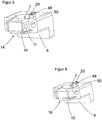
- FIG. 5 shows the mounting base 6 with the parts FIG. 4 in a mounted state.
- the fixing slide 10 is shown in a non-actuated state, namely in a locking position 14.
- the passage opening of the fixing slide 10 and the passage opening 7 of the mounting base 6 is shifted from one another, so that the fixing slide 10 projects into the fastening groove of the fastening flange, not shown.
- the actuating element 48 of the locking slide 20 is flush with a side surface 50 of the mounting base. 6
- blocking means 11 are provided, whereby the fixing slide 10 is locked in the locking position 14.
- the actuated blocking means 11 ensures that the electronic device or the sensor housing is not solved by accidental actuation of the fixing slide 10 and the actuating means, so that this would get into the mounting position, so that the electronic device or the sensor housing is no longer fixed or locked.
- the blocking agent 11 is actuated, the fixing slide 10 or the actuating means can not be actuated. Only after a release of the blocking agent 11, the fixing slide 10 and the actuating means can be actuated.
- FIG. 6 shows the mounting base 6 FIG. 5 wherein the fixing slide 10 is shown in an actuated state, so that the fixing slide 10 is arranged in a mounting position 18, so that the passage opening of the Fix istsschiebers 10 and the through hole 7 of the mounting base 6 are flush over each other, so that the mounting flange 4 of the sensor housing in the Through opening of the fixing slide 10 and the mounting base 6 can be inserted.
- the actuating element 48 of the locking slide 20 projects from a side surface 50 of the mounting base 6.
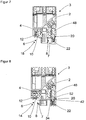
- FIG. 7 shows the sensor housing 2 with the mounting flange 4 and the mounting base 6 in a sectional view.
- the fixing slide 10 is shown in an actuated state, so that the passage opening 7 of the mounting base 6 and the passage opening 8 of the Fix mich istsschiebers 10 are congruent.
- This position of the fixing slide 10 is fixed by the position of the locking slide 20.
- the locking slide 20 is held by the second spring 22 in this position.
- the locking slide 20, or the actuating element 48 of the locking slide 20 projects beyond the side surface of the mounting base 6.
- the fixing slide 10 is biased in this position by the first spring 12.
- the sensor housing 2 can be inserted with the mounting flange 4 in the through hole 7 of the mounting flange 6.
- a side wall of the sensor housing 2 reaches the locking slide 20 and the actuating element 48 of the locking slide 20, whereby it is pressed in the direction of the second spring 22.
- This condition is in FIG. 8 shown.
- the locking slide 20 is moved in the direction of the second spring 22.
- the locking slide 20 is displaced such that the diameter 52 of the locking slide 20 is reduced at the location of the recess 42 of the Fix mich michssensschiebers 10, whereby the recess 42 of the Fix mich michssensschiebers 10 is no longer fixed by the locking slide 20 and the Fix réellesschieber 10 by the first spring 12 is moved in the direction of the first spring 12, so that the fixing slide 10 engages in the mounting groove 34 of the mounting flange 4, whereby the mounting flange 4 is fixed axially in the mounting base 6.
- a radial fixation can additionally be achieved.
- the fixing slide 10 is again pressed against the first spring 12. Thereby, the through holes 7 of the mounting base 7 and the fixing slide 10 are again congruent, whereby the mounting flange 4 can be removed axially from the mounting base 6.
- the locking slide 20 is moved by the second spring 22 again in the direction of the sensor housing 2, whereby the fixing slide 10 is fixed by the recess back in the mounting position 18.
- FIG. 9 shows in perspective the mounting base 6 with the fixing slide 10 and the locking slide 20, but without sensor housing, so that the passage opening 7 of the mounting base 6 is visible.
- FIG. 9 shows the fixing slide 10 in a locking position 14 in which it is held by the first spring. In this position, the sensor housing is either fixed in the mounting base 6 or can not be inserted into the through hole 7.
- FIG. 10 shows a sectional view in the direction AA according to FIG. 9 .
- FIG. 11 shows in perspective the mounting base 6 with the fixing slide 10 and the locking slide 20, but without sensor housing, so that the passage opening 7 of the mounting base 6 is visible.
- FIG. 11 shows the fixing slide 10 in a mounting position 18 in which it is held, for example, against the spring force of the first spring by a finger. In this position, the sensor housing 2 is either not fixed in the mounting base 6 or can be inserted into the through hole 7 for mounting.
- FIG. 12 shows a sectional view in the direction AA according to FIG. 11 .
- FIG. 13 shows a sectional view in the direction BB according to FIG. 11 ,
- the passage opening 7 of the mounting base 6 and the passage opening 8 of the Fix istsschiebers 8 is flush.
- the larger diameter 52 of the locking slide 20 fixes the fixing slide 10 via its recess 42.
- the recess 42 of the fixing slide 10 has a first distance 56 and a second further distance 58.
- the larger diameter 52 of the locking slide 20th engages in the second further distance 58 of the recess 42 of the fixing slide 10, so that it can not be moved in the direction of the first spring, not shown.
- a sensor housing is inserted with a mounting flange in the mounting base 6, the locking slide 20 is displaced at the location of the fixing slide 10 of the larger diameter 52 to a smaller diameter 54. This is in FIG. 14 shown.
- FIG. 14 shows a sectional view in the direction BB according to FIG. 9
- FIG. 14 shows the smaller diameter 54 of the locking slide 20. Because the larger diameter 52 of the locking slide 20 no longer fixes the fixing slide 10, the fixing slide 10 is pressed by the first spring in the direction of the first spring 12, so that the recess 42 with the first smaller distance 56 engages in the smaller diameter 54 of the locking slide 20 and fixes this together with the first spring 12 in a locking position 14. In this case, the passage opening 8 of the fixing slide 10 and the passage opening 7 of the mounting base 6 are no longer flush with each other.
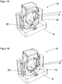
- FIG. 15 shows in perspective the mounting base 6 with the fixing slide 10 and the locking slide 20, but without sensor housing 2, so that the passage opening 7 of the mounting base 6 is visible in a transparent representation.
- FIG. 15 shows the fixing slide 10 in a locking position 14 in which it is held by the first spring. In this position, the sensor housing is either fixed in the mounting base 6 or can not be inserted into the through hole 7.
- FIG. 16 shows in perspective the mounting base 6 with the fixing slide 10 and the locking slide 20, but without sensor housing 2, so that the passage opening 7 of the mounting base 6 is visible in a transparent representation.
- FIG. 16 shows the fixing slide 10 in a mounting position 18 in which it is held, for example, against the spring force of the first spring by a finger. In this position, the sensor housing is either not fixed in the mounting base 6 or can be inserted into the through hole 7 for mounting.
Landscapes
- Physics & Mathematics (AREA)
- General Physics & Mathematics (AREA)
- Connection Of Plates (AREA)
- Mounting Components In General For Electric Apparatus (AREA)
Claims (12)
- Dispositif de fixation d'un appareil électronique (3), comportant une bride de fixation (4) et un socle de fixation (6), la bride de fixation (4) pouvant être positionnée dans une ouverture traversante (8) dans le socle de fixation (6) et la bride de fixation (4) pouvant être verrouillée dans le socle de fixation (6),
dans lequel
le dispositif de fixation comprend un coulisseau de fixation (10) et un coulisseau de verrouillage (20), le coulisseau de fixation (10) est agencé mobile en coulissement sur le socle de fixation (6), afin de verrouiller et/ou de détacher la bride de fixation (4) dans le socle de fixation (6), caractérisé en ce que le coulisseau de fixation (10) présente une surface d'actionnement (16),
le coulisseau de fixation (10) est amené dans une position de montage (18) pour la bride de fixation (4) par déplacement par la surface d'actionnement,
la bride de fixation (4) est susceptible d'être introduite dans l'ouverture traversante (8) du socle de fixation (6), le coulisseau de fixation (10) est retenu dans la position de montage (81) par le coulisseau de verrouillage (20). - Dispositif de fixation selon la revendication 1, caractérisé en ce que le coulisseau de fixation (10) comprend un premier ressort (12), le coulisseau de fixation (10) étant positionné dans la position de verrouillage (14) par le premier ressort (12).
- Dispositif de fixation selon la revendication 1, caractérisé en ce que le coulisseau de verrouillage (20) est positionné par un second ressort (22).
- Dispositif de fixation selon l'une des revendications précédentes 1 à 3,
caractérisé en ce que lors de l'introduction de la bride de fixation (4) dans le socle de fixation (6), le coulisseau de verrouillage (20) est déplaçable par l'appareil électronique (3), grâce à quoi un verrouillage du coulisseau de fixation (10) par le coulisseau de verrouillage (20) est détaché, grâce à quoi le coulisseau de fixation (10) est déplacé d'une position de montage (18) jusque dans la position de verrouillage (14) par le premier ressort (12). - Dispositif de fixation selon l'une des revendications précédentes 3 à 4,
caractérisé en ce que lors du détachement du socle de fixation par le coulisseau de fixation, le socle de fixation est apte à être éjecté par le coulisseau de verrouillage en raison du second ressort. - Dispositif de fixation selon l'une des revendications précédentes, caractérisé en ce que il est prévu des moyens de blocage (11) par lesquels le coulisseau de fixation (10) est apte à être bloqué dans la position de verrouillage (14).
- Procédé de fixation d'un appareil électronique (3) avec une bride de fixation (4) dans un socle de fixation (6), dans lequel la bride de fixation (4) est positionnée dans le socle de fixation (6), la bride de fixation (4) est verrouillée dans le socle de fixation (6),
et dans lequel
il est prévu un coulisseau de fixation (10) qui est déplacé sur le socle de fixation (6) afin de verrouiller et/ou de détacher la bride de fixation (4) dans le socle de fixation (6), caractérisé en ce que le coulisseau de fixation (10) présente une surface d'actionnement (16), le coulisseau de fixation (10) est amené dans une position de montage pour la bride de fixation (4) par déplacement par la surface d'actionnement (16), la bride de fixation (4) est introduite dans l'ouverture traversante (8) du socle de fixation (6), le coulisseau de fixation (10) est retenu dans la position de montage (18) par un coulisseau de verrouillage (20). - Procédé de fixation d'un appareil électronique (3) selon la revendication 7, caractérisé en ce que le coulisseau de fixation (10) présente un premier ressort (12), le premier ressort (12) fixant le coulisseau de fixation (10) dans la position de verrouillage (14).
- Procédé de fixation d'un boîtier de capteur (2) selon la revendication 7, caractérisé en ce que le coulisseau de verrouillage (20) est fixé par un second ressort (22).
- Procédé de fixation d'un appareil électronique (3) selon l'une des revendications précédentes 7 à 9, caractérisé en ce que lors de l'introduction de la bride de fixation (4) dans le socle de fixation (6), le coulisseau de verrouillage (20) est déplacé par l'appareil électronique (2), ce qui fait détacher un verrouillage du coulisseau de fixation (10) par le coulisseau de verrouillage (20), ce qui fait déplacer le coulisseau de fixation (10) depuis la position de montage (18) jusque dans la position de verrouillage (14) par le premier ressort (12).
- Procédé de fixation d'un appareil électronique (3) selon l'une des revendications précédentes 7 à 10, caractérisé en ce que lors du détachement du socle de fixation par le coulisseau de fixation, le socle de fixation est éjecté par le coulisseau de verrouillage en raison du second ressort.
- Procédé de fixation d'un appareil électronique (3) selon l'une des revendications précédentes 7 à 11, caractérisé en ce qu'il est prévu des moyens de blocage (11) par lesquels le coulisseau de fixation (10) est bloqué dans la position de verrouillage (14).
Priority Applications (3)
| Application Number | Priority Date | Filing Date | Title |
|---|---|---|---|
| EP14180836.0A EP2985573B1 (fr) | 2014-08-13 | 2014-08-13 | Appareil et procédé de fixation d'un dispositif électronique |
| US14/817,460 US10060771B2 (en) | 2014-08-13 | 2015-08-04 | Fastening apparatus for an electronic device and method for fastening an electronic device |
| JP2015153903A JP6110446B2 (ja) | 2014-08-13 | 2015-08-04 | 電子機器用取り付け装置及び電子機器の取り付け方法 |
Applications Claiming Priority (1)
| Application Number | Priority Date | Filing Date | Title |
|---|---|---|---|
| EP14180836.0A EP2985573B1 (fr) | 2014-08-13 | 2014-08-13 | Appareil et procédé de fixation d'un dispositif électronique |
Publications (2)
| Publication Number | Publication Date |
|---|---|
| EP2985573A1 EP2985573A1 (fr) | 2016-02-17 |
| EP2985573B1 true EP2985573B1 (fr) | 2017-10-11 |
Family
ID=51301210
Family Applications (1)
| Application Number | Title | Priority Date | Filing Date |
|---|---|---|---|
| EP14180836.0A Active EP2985573B1 (fr) | 2014-08-13 | 2014-08-13 | Appareil et procédé de fixation d'un dispositif électronique |
Country Status (3)
| Country | Link |
|---|---|
| US (1) | US10060771B2 (fr) |
| EP (1) | EP2985573B1 (fr) |
| JP (1) | JP6110446B2 (fr) |
Families Citing this family (5)
| Publication number | Priority date | Publication date | Assignee | Title |
|---|---|---|---|---|
| DE102016107044B4 (de) * | 2016-04-15 | 2017-11-16 | Rittal Gmbh & Co. Kg | Elektronisches Gerät für den Einbau in einem Schaltschrank, das ein erstes und ein zweites Befestigungsmittel aufweist |
| DE102019101273B4 (de) | 2019-01-18 | 2020-10-22 | Sick Ag | Befestigungsvorrichtung zum Halten eines Sensors und Verfahren zum Befestigen und Justieren eines Sensors |
| DE202019100279U1 (de) | 2019-01-18 | 2020-04-23 | Sick Ag | Befestigungsvorrichtung zum Halten eines Sensors |
| US10965001B2 (en) * | 2019-05-30 | 2021-03-30 | Rosemount Inc. | Universal industrial transmitter mounting |
| DE102022111019A1 (de) | 2022-05-04 | 2023-11-09 | Ifm Electronic Gmbh | Vorrichtung zum Befestigen eines elektrischen Geräts |
Citations (3)
| Publication number | Priority date | Publication date | Assignee | Title |
|---|---|---|---|---|
| GB2302611A (en) * | 1995-06-24 | 1997-01-22 | Nec Corp | Lock structure for cover of electronic appliance |
| DE10049111A1 (de) * | 1999-10-04 | 2001-06-13 | Matsushita Electric Ind Co Ltd | Mehrwegeschalter und ein diesen verwendendes elektronisches Gerät |
| US7281940B1 (en) * | 2006-11-28 | 2007-10-16 | Inventec Corporation | Removable electrical interface device and electronic apparatus having the same |
Family Cites Families (22)
| Publication number | Priority date | Publication date | Assignee | Title |
|---|---|---|---|---|
| JPS59133484A (ja) * | 1983-01-20 | 1984-07-31 | 松下電器産業株式会社 | 保持装置 |
| JPS6056212U (ja) * | 1983-09-26 | 1985-04-19 | 三菱電機株式会社 | 回転角検出器の固定装置 |
| US4671697A (en) * | 1984-05-09 | 1987-06-09 | Mitsubishi Denki Kabushiki Kaisha | Apparatus for mounting electrical appliance on frame |
| JPS62176796U (fr) * | 1986-04-28 | 1987-11-10 | ||
| DE9406196U1 (de) * | 1994-04-14 | 1995-08-10 | Gier & Partner GmbH, 40789 Monheim | Rohrleitungs-Pass-Stück, insbesondere für opto-elektronische Volumenstrom-Messungen in Rohrleitungen |
| KR100187223B1 (ko) * | 1995-07-29 | 1999-05-01 | 김광호 | 압축기의 머플러장치 |
| JP3393575B2 (ja) * | 1997-01-31 | 2003-04-07 | ワイケイケイ株式会社 | 自動停止装置付スライドファスナー用スライダー |
| JPH10246287A (ja) * | 1997-03-07 | 1998-09-14 | Fujitsu Ltd | 台足構造 |
| JP2877130B2 (ja) | 1997-03-24 | 1999-03-31 | 日本電気株式会社 | 筐体の外線導入部構造 |
| US5730342A (en) * | 1997-04-11 | 1998-03-24 | Tien; Tse-Hsiung | Mobile telephone fastening |
| KR200162310Y1 (ko) * | 1997-09-20 | 1999-12-15 | 김동주 | 무선전화기용 홀더의 착탈구조 |
| US6283348B1 (en) * | 2000-04-05 | 2001-09-04 | Chin-Yang Wang | Cellular telephone clip |
| US6955279B1 (en) * | 2002-12-04 | 2005-10-18 | Garmin Ltd. | Carrying assembly and method for securement of electronic devices |
| DE20301144U1 (de) | 2003-01-24 | 2004-06-03 | Pepperl + Fuchs Gmbh | Befestigungsvorrichtung, bestehend aus einem Befestigungssockel und einem elektrischen Gerät |
| JP4149369B2 (ja) * | 2003-12-10 | 2008-09-10 | Ykk株式会社 | 自動停止装置付スライドファスナー用スライダー |
| JP4428199B2 (ja) * | 2004-01-14 | 2010-03-10 | 株式会社デンソー | 電子制御装置 |
| WO2005089582A2 (fr) * | 2004-03-18 | 2005-09-29 | Bodypoint Designs, Inc. | Support lateral pivotant et ensemble a liberation rapide pour dispositif de stabilisation sous-abdominale |
| US8210008B2 (en) * | 2008-08-08 | 2012-07-03 | Lear Corporation | Ignition module with multi-beam spring |
| US20100071168A1 (en) * | 2008-09-24 | 2010-03-25 | Miller David A | Earpiece retainer |
| US8613564B2 (en) * | 2011-04-21 | 2013-12-24 | Christopher Busch | Quick disconnect securement device |
| CN103313569A (zh) * | 2012-03-15 | 2013-09-18 | 鸿富锦精密工业(深圳)有限公司 | 支架固定模组 |
| CN103582331A (zh) * | 2012-07-27 | 2014-02-12 | 鸿富锦精密工业(深圳)有限公司 | 电子装置壳体 |
-
2014
- 2014-08-13 EP EP14180836.0A patent/EP2985573B1/fr active Active
-
2015
- 2015-08-04 US US14/817,460 patent/US10060771B2/en active Active
- 2015-08-04 JP JP2015153903A patent/JP6110446B2/ja active Active
Patent Citations (3)
| Publication number | Priority date | Publication date | Assignee | Title |
|---|---|---|---|---|
| GB2302611A (en) * | 1995-06-24 | 1997-01-22 | Nec Corp | Lock structure for cover of electronic appliance |
| DE10049111A1 (de) * | 1999-10-04 | 2001-06-13 | Matsushita Electric Ind Co Ltd | Mehrwegeschalter und ein diesen verwendendes elektronisches Gerät |
| US7281940B1 (en) * | 2006-11-28 | 2007-10-16 | Inventec Corporation | Removable electrical interface device and electronic apparatus having the same |
Also Published As
| Publication number | Publication date |
|---|---|
| EP2985573A1 (fr) | 2016-02-17 |
| JP6110446B2 (ja) | 2017-04-05 |
| US20160047678A1 (en) | 2016-02-18 |
| JP2016042081A (ja) | 2016-03-31 |
| US10060771B2 (en) | 2018-08-28 |
Similar Documents
| Publication | Publication Date | Title |
|---|---|---|
| EP2985573B1 (fr) | Appareil et procédé de fixation d'un dispositif électronique | |
| EP2301115B1 (fr) | Dispositif de connexion électrique | |
| EP1841016B1 (fr) | Connecteur à fiches métallique | |
| EP3235061B1 (fr) | Borne de connexion électrique | |
| DE102012111408B3 (de) | Verriegelungsmechanismus für Steckverbinder | |
| DE202017101843U1 (de) | Steckerbaugruppe für einen Plasmabogenbrenner | |
| DE102014206431A1 (de) | Connector Position Assurance (CPA) und Steckverbinderanordnung mit einer CPA | |
| EP2067577A1 (fr) | Dispositif de fixation pour embout | |
| DE102017001931A1 (de) | Steckerkupplung mit Zugentlastung für ein Verbindungskabel | |
| DE19941794A1 (de) | Anordnung eines Druckstückes in einer Synchronisiereinrichtung | |
| DE102019204763A1 (de) | Steckbolzen mit Betätigungselement zum lösbaren Sichern oder Halten von Komponenten eines Presswerkzeugs | |
| DE102018008954B4 (de) | Befestigungsclip zum Befestigen eines Teils an einem anderen, ein Loch aufweisenden Teil | |
| DE102015204501B4 (de) | Schnellwechselsystem für Greiferelemente zum Erfassen und Transportieren von Werkstücken | |
| EP1350962B1 (fr) | Ensemble de modules à éléments d'encliquetage | |
| DE102015213688B4 (de) | Vorrichtung zum Fixieren eines Katheters | |
| DE102021114573A1 (de) | Bajonettverbindung zur lösbaren Verbindung eines ersten Bauteils und eines zweiten Bauteils | |
| EP3022807B1 (fr) | Dispositif de verrouillage de connecteurs enfichables | |
| CH662159A5 (de) | Loesbare steckverbindung fuer einen stift in einer stecktafel. | |
| DE102013012439B3 (de) | Schälvorrichtung, Schälwerkzeug und Verfahren zum Abschälen | |
| DE4236794C2 (de) | Elektrische Steckverbindung | |
| EP3687007B1 (fr) | Appareil d'installation électrique à levier de libération | |
| DE19652271C2 (de) | Kontaktklemme | |
| DE102011107957B4 (de) | Scharnierbauteil mit Clipbefestigung | |
| DE10119245B4 (de) | Steckverbinder mit Überwurfkappe | |
| DE202017106565U1 (de) | Rohrschneider |
Legal Events
| Date | Code | Title | Description |
|---|---|---|---|
| PUAI | Public reference made under article 153(3) epc to a published international application that has entered the european phase |
Free format text: ORIGINAL CODE: 0009012 |
|
| AK | Designated contracting states |
Kind code of ref document: A1 Designated state(s): AL AT BE BG CH CY CZ DE DK EE ES FI FR GB GR HR HU IE IS IT LI LT LU LV MC MK MT NL NO PL PT RO RS SE SI SK SM TR |
|
| AX | Request for extension of the european patent |
Extension state: BA ME |
|
| 17P | Request for examination filed |
Effective date: 20160722 |
|
| RBV | Designated contracting states (corrected) |
Designated state(s): AL AT BE BG CH CY CZ DE DK EE ES FI FR GB GR HR HU IE IS IT LI LT LU LV MC MK MT NL NO PL PT RO RS SE SI SK SM TR |
|
| 17Q | First examination report despatched |
Effective date: 20161019 |
|
| GRAP | Despatch of communication of intention to grant a patent |
Free format text: ORIGINAL CODE: EPIDOSNIGR1 |
|
| RIC1 | Information provided on ipc code assigned before grant |
Ipc: G01D 11/30 20060101ALI20170428BHEP Ipc: G01D 11/24 20060101AFI20170428BHEP |
|
| INTG | Intention to grant announced |
Effective date: 20170515 |
|
| GRAS | Grant fee paid |
Free format text: ORIGINAL CODE: EPIDOSNIGR3 |
|
| GRAA | (expected) grant |
Free format text: ORIGINAL CODE: 0009210 |
|
| AK | Designated contracting states |
Kind code of ref document: B1 Designated state(s): AL AT BE BG CH CY CZ DE DK EE ES FI FR GB GR HR HU IE IS IT LI LT LU LV MC MK MT NL NO PL PT RO RS SE SI SK SM TR |
|
| REG | Reference to a national code |
Ref country code: GB Ref legal event code: FG4D Free format text: NOT ENGLISH |
|
| REG | Reference to a national code |
Ref country code: CH Ref legal event code: EP |
|
| REG | Reference to a national code |
Ref country code: IE Ref legal event code: FG4D Free format text: LANGUAGE OF EP DOCUMENT: GERMAN |
|
| REG | Reference to a national code |
Ref country code: AT Ref legal event code: REF Ref document number: 936457 Country of ref document: AT Kind code of ref document: T Effective date: 20171115 |
|
| REG | Reference to a national code |
Ref country code: DE Ref legal event code: R096 Ref document number: 502014005751 Country of ref document: DE |
|
| REG | Reference to a national code |
Ref country code: NL Ref legal event code: MP Effective date: 20171011 |
|
| REG | Reference to a national code |
Ref country code: LT Ref legal event code: MG4D |
|
| PG25 | Lapsed in a contracting state [announced via postgrant information from national office to epo] |
Ref country code: NL Free format text: LAPSE BECAUSE OF FAILURE TO SUBMIT A TRANSLATION OF THE DESCRIPTION OR TO PAY THE FEE WITHIN THE PRESCRIBED TIME-LIMIT Effective date: 20171011 |
|
| PG25 | Lapsed in a contracting state [announced via postgrant information from national office to epo] |
Ref country code: NO Free format text: LAPSE BECAUSE OF FAILURE TO SUBMIT A TRANSLATION OF THE DESCRIPTION OR TO PAY THE FEE WITHIN THE PRESCRIBED TIME-LIMIT Effective date: 20180111 Ref country code: FI Free format text: LAPSE BECAUSE OF FAILURE TO SUBMIT A TRANSLATION OF THE DESCRIPTION OR TO PAY THE FEE WITHIN THE PRESCRIBED TIME-LIMIT Effective date: 20171011 Ref country code: SE Free format text: LAPSE BECAUSE OF FAILURE TO SUBMIT A TRANSLATION OF THE DESCRIPTION OR TO PAY THE FEE WITHIN THE PRESCRIBED TIME-LIMIT Effective date: 20171011 Ref country code: ES Free format text: LAPSE BECAUSE OF FAILURE TO SUBMIT A TRANSLATION OF THE DESCRIPTION OR TO PAY THE FEE WITHIN THE PRESCRIBED TIME-LIMIT Effective date: 20171011 Ref country code: LT Free format text: LAPSE BECAUSE OF FAILURE TO SUBMIT A TRANSLATION OF THE DESCRIPTION OR TO PAY THE FEE WITHIN THE PRESCRIBED TIME-LIMIT Effective date: 20171011 |
|
| PG25 | Lapsed in a contracting state [announced via postgrant information from national office to epo] |
Ref country code: IS Free format text: LAPSE BECAUSE OF FAILURE TO SUBMIT A TRANSLATION OF THE DESCRIPTION OR TO PAY THE FEE WITHIN THE PRESCRIBED TIME-LIMIT Effective date: 20180211 Ref country code: HR Free format text: LAPSE BECAUSE OF FAILURE TO SUBMIT A TRANSLATION OF THE DESCRIPTION OR TO PAY THE FEE WITHIN THE PRESCRIBED TIME-LIMIT Effective date: 20171011 Ref country code: GR Free format text: LAPSE BECAUSE OF FAILURE TO SUBMIT A TRANSLATION OF THE DESCRIPTION OR TO PAY THE FEE WITHIN THE PRESCRIBED TIME-LIMIT Effective date: 20180112 Ref country code: RS Free format text: LAPSE BECAUSE OF FAILURE TO SUBMIT A TRANSLATION OF THE DESCRIPTION OR TO PAY THE FEE WITHIN THE PRESCRIBED TIME-LIMIT Effective date: 20171011 Ref country code: LV Free format text: LAPSE BECAUSE OF FAILURE TO SUBMIT A TRANSLATION OF THE DESCRIPTION OR TO PAY THE FEE WITHIN THE PRESCRIBED TIME-LIMIT Effective date: 20171011 Ref country code: BG Free format text: LAPSE BECAUSE OF FAILURE TO SUBMIT A TRANSLATION OF THE DESCRIPTION OR TO PAY THE FEE WITHIN THE PRESCRIBED TIME-LIMIT Effective date: 20180111 |
|
| REG | Reference to a national code |
Ref country code: DE Ref legal event code: R097 Ref document number: 502014005751 Country of ref document: DE |
|
| PG25 | Lapsed in a contracting state [announced via postgrant information from national office to epo] |
Ref country code: SK Free format text: LAPSE BECAUSE OF FAILURE TO SUBMIT A TRANSLATION OF THE DESCRIPTION OR TO PAY THE FEE WITHIN THE PRESCRIBED TIME-LIMIT Effective date: 20171011 Ref country code: DK Free format text: LAPSE BECAUSE OF FAILURE TO SUBMIT A TRANSLATION OF THE DESCRIPTION OR TO PAY THE FEE WITHIN THE PRESCRIBED TIME-LIMIT Effective date: 20171011 Ref country code: EE Free format text: LAPSE BECAUSE OF FAILURE TO SUBMIT A TRANSLATION OF THE DESCRIPTION OR TO PAY THE FEE WITHIN THE PRESCRIBED TIME-LIMIT Effective date: 20171011 Ref country code: CZ Free format text: LAPSE BECAUSE OF FAILURE TO SUBMIT A TRANSLATION OF THE DESCRIPTION OR TO PAY THE FEE WITHIN THE PRESCRIBED TIME-LIMIT Effective date: 20171011 |
|
| PLBE | No opposition filed within time limit |
Free format text: ORIGINAL CODE: 0009261 |
|
| STAA | Information on the status of an ep patent application or granted ep patent |
Free format text: STATUS: NO OPPOSITION FILED WITHIN TIME LIMIT |
|
| PG25 | Lapsed in a contracting state [announced via postgrant information from national office to epo] |
Ref country code: RO Free format text: LAPSE BECAUSE OF FAILURE TO SUBMIT A TRANSLATION OF THE DESCRIPTION OR TO PAY THE FEE WITHIN THE PRESCRIBED TIME-LIMIT Effective date: 20171011 Ref country code: PL Free format text: LAPSE BECAUSE OF FAILURE TO SUBMIT A TRANSLATION OF THE DESCRIPTION OR TO PAY THE FEE WITHIN THE PRESCRIBED TIME-LIMIT Effective date: 20171011 Ref country code: SM Free format text: LAPSE BECAUSE OF FAILURE TO SUBMIT A TRANSLATION OF THE DESCRIPTION OR TO PAY THE FEE WITHIN THE PRESCRIBED TIME-LIMIT Effective date: 20171011 |
|
| 26N | No opposition filed |
Effective date: 20180712 |
|
| PG25 | Lapsed in a contracting state [announced via postgrant information from national office to epo] |
Ref country code: MT Free format text: LAPSE BECAUSE OF FAILURE TO SUBMIT A TRANSLATION OF THE DESCRIPTION OR TO PAY THE FEE WITHIN THE PRESCRIBED TIME-LIMIT Effective date: 20171011 |
|
| PG25 | Lapsed in a contracting state [announced via postgrant information from national office to epo] |
Ref country code: SI Free format text: LAPSE BECAUSE OF FAILURE TO SUBMIT A TRANSLATION OF THE DESCRIPTION OR TO PAY THE FEE WITHIN THE PRESCRIBED TIME-LIMIT Effective date: 20171011 |
|
| PG25 | Lapsed in a contracting state [announced via postgrant information from national office to epo] |
Ref country code: MC Free format text: LAPSE BECAUSE OF FAILURE TO SUBMIT A TRANSLATION OF THE DESCRIPTION OR TO PAY THE FEE WITHIN THE PRESCRIBED TIME-LIMIT Effective date: 20171011 |
|
| GBPC | Gb: european patent ceased through non-payment of renewal fee |
Effective date: 20180813 |
|
| PG25 | Lapsed in a contracting state [announced via postgrant information from national office to epo] |
Ref country code: LU Free format text: LAPSE BECAUSE OF NON-PAYMENT OF DUE FEES Effective date: 20180813 |
|
| REG | Reference to a national code |
Ref country code: BE Ref legal event code: MM Effective date: 20180831 |
|
| REG | Reference to a national code |
Ref country code: IE Ref legal event code: MM4A |
|
| PG25 | Lapsed in a contracting state [announced via postgrant information from national office to epo] |
Ref country code: IE Free format text: LAPSE BECAUSE OF NON-PAYMENT OF DUE FEES Effective date: 20180813 |
|
| PG25 | Lapsed in a contracting state [announced via postgrant information from national office to epo] |
Ref country code: BE Free format text: LAPSE BECAUSE OF NON-PAYMENT OF DUE FEES Effective date: 20180831 Ref country code: FR Free format text: LAPSE BECAUSE OF NON-PAYMENT OF DUE FEES Effective date: 20180831 |
|
| PG25 | Lapsed in a contracting state [announced via postgrant information from national office to epo] |
Ref country code: GB Free format text: LAPSE BECAUSE OF NON-PAYMENT OF DUE FEES Effective date: 20180813 |
|
| PG25 | Lapsed in a contracting state [announced via postgrant information from national office to epo] |
Ref country code: TR Free format text: LAPSE BECAUSE OF FAILURE TO SUBMIT A TRANSLATION OF THE DESCRIPTION OR TO PAY THE FEE WITHIN THE PRESCRIBED TIME-LIMIT Effective date: 20171011 |
|
| PG25 | Lapsed in a contracting state [announced via postgrant information from national office to epo] |
Ref country code: PT Free format text: LAPSE BECAUSE OF FAILURE TO SUBMIT A TRANSLATION OF THE DESCRIPTION OR TO PAY THE FEE WITHIN THE PRESCRIBED TIME-LIMIT Effective date: 20171011 |
|
| PG25 | Lapsed in a contracting state [announced via postgrant information from national office to epo] |
Ref country code: HU Free format text: LAPSE BECAUSE OF FAILURE TO SUBMIT A TRANSLATION OF THE DESCRIPTION OR TO PAY THE FEE WITHIN THE PRESCRIBED TIME-LIMIT; INVALID AB INITIO Effective date: 20140813 Ref country code: CY Free format text: LAPSE BECAUSE OF FAILURE TO SUBMIT A TRANSLATION OF THE DESCRIPTION OR TO PAY THE FEE WITHIN THE PRESCRIBED TIME-LIMIT Effective date: 20171011 Ref country code: MK Free format text: LAPSE BECAUSE OF NON-PAYMENT OF DUE FEES Effective date: 20171011 |
|
| PG25 | Lapsed in a contracting state [announced via postgrant information from national office to epo] |
Ref country code: AL Free format text: LAPSE BECAUSE OF FAILURE TO SUBMIT A TRANSLATION OF THE DESCRIPTION OR TO PAY THE FEE WITHIN THE PRESCRIBED TIME-LIMIT Effective date: 20171011 |
|
| REG | Reference to a national code |
Ref country code: AT Ref legal event code: MM01 Ref document number: 936457 Country of ref document: AT Kind code of ref document: T Effective date: 20190813 |
|
| PG25 | Lapsed in a contracting state [announced via postgrant information from national office to epo] |
Ref country code: AT Free format text: LAPSE BECAUSE OF NON-PAYMENT OF DUE FEES Effective date: 20190813 |
|
| PGFP | Annual fee paid to national office [announced via postgrant information from national office to epo] |
Ref country code: DE Payment date: 20240819 Year of fee payment: 11 |
|
| PGFP | Annual fee paid to national office [announced via postgrant information from national office to epo] |
Ref country code: CH Payment date: 20240901 Year of fee payment: 11 |
|
| PGFP | Annual fee paid to national office [announced via postgrant information from national office to epo] |
Ref country code: IT Payment date: 20240830 Year of fee payment: 11 |