EP2985385A1 - Spraying device for spraying a liquid product onto paper sheet - Google Patents
Spraying device for spraying a liquid product onto paper sheet Download PDFInfo
- Publication number
- EP2985385A1 EP2985385A1 EP14380022.5A EP14380022A EP2985385A1 EP 2985385 A1 EP2985385 A1 EP 2985385A1 EP 14380022 A EP14380022 A EP 14380022A EP 2985385 A1 EP2985385 A1 EP 2985385A1
- Authority
- EP
- European Patent Office
- Prior art keywords
- spraying
- paper sheet
- liquid product
- spray chamber
- guide rollers
- Prior art date
- Legal status (The legal status is an assumption and is not a legal conclusion. Google has not performed a legal analysis and makes no representation as to the accuracy of the status listed.)
- Withdrawn
Links
Images


Classifications
-
- D—TEXTILES; PAPER
- D21—PAPER-MAKING; PRODUCTION OF CELLULOSE
- D21H—PULP COMPOSITIONS; PREPARATION THEREOF NOT COVERED BY SUBCLASSES D21C OR D21D; IMPREGNATING OR COATING OF PAPER; TREATMENT OF FINISHED PAPER NOT COVERED BY CLASS B31 OR SUBCLASS D21G; PAPER NOT OTHERWISE PROVIDED FOR
- D21H23/00—Processes or apparatus for adding material to the pulp or to the paper
- D21H23/02—Processes or apparatus for adding material to the pulp or to the paper characterised by the manner in which substances are added
- D21H23/22—Addition to the formed paper
- D21H23/50—Spraying or projecting
-
- B—PERFORMING OPERATIONS; TRANSPORTING
- B05—SPRAYING OR ATOMISING IN GENERAL; APPLYING FLUENT MATERIALS TO SURFACES, IN GENERAL
- B05B—SPRAYING APPARATUS; ATOMISING APPARATUS; NOZZLES
- B05B13/00—Machines or plants for applying liquids or other fluent materials to surfaces of objects or other work by spraying, not covered by groups B05B1/00 - B05B11/00
- B05B13/02—Means for supporting work; Arrangement or mounting of spray heads; Adaptation or arrangement of means for feeding work
- B05B13/0207—Means for supporting work; Arrangement or mounting of spray heads; Adaptation or arrangement of means for feeding work the work being an elongated body, e.g. wire or pipe
-
- B—PERFORMING OPERATIONS; TRANSPORTING
- B05—SPRAYING OR ATOMISING IN GENERAL; APPLYING FLUENT MATERIALS TO SURFACES, IN GENERAL
- B05B—SPRAYING APPARATUS; ATOMISING APPARATUS; NOZZLES
- B05B15/00—Details of spraying plant or spraying apparatus not otherwise provided for; Accessories
- B05B15/50—Arrangements for cleaning; Arrangements for preventing deposits, drying-out or blockage; Arrangements for detecting improper discharge caused by the presence of foreign matter
- B05B15/55—Arrangements for cleaning; Arrangements for preventing deposits, drying-out or blockage; Arrangements for detecting improper discharge caused by the presence of foreign matter using cleaning fluids
- B05B15/555—Arrangements for cleaning; Arrangements for preventing deposits, drying-out or blockage; Arrangements for detecting improper discharge caused by the presence of foreign matter using cleaning fluids discharged by cleaning nozzles
-
- B—PERFORMING OPERATIONS; TRANSPORTING
- B05—SPRAYING OR ATOMISING IN GENERAL; APPLYING FLUENT MATERIALS TO SURFACES, IN GENERAL
- B05B—SPRAYING APPARATUS; ATOMISING APPARATUS; NOZZLES
- B05B15/00—Details of spraying plant or spraying apparatus not otherwise provided for; Accessories
- B05B15/60—Arrangements for mounting, supporting or holding spraying apparatus
- B05B15/65—Mounting arrangements for fluid connection of the spraying apparatus or its outlets to flow conduits
- B05B15/652—Mounting arrangements for fluid connection of the spraying apparatus or its outlets to flow conduits whereby the jet can be oriented
Definitions
- the present invention relates to a spraying device for spraying a liquid product onto a paper sheet useful for applying a coating of liquid product sprayed onto a moving paper sheet web.
- the device of the present invention is useful for creating a barrier coating against fats, oil and water, and/or an anti-scratch coating, and/or a pigmentation coating, and/or a coating of any other surface treatment on a paper sheet web, whereby obtaining a waterproof paper sheet web which can be used, for example, in forming hydrophobic corrugated cardboard, or a paper sheet with other properties and for other uses.
- Document WO 2013167771 A1 discloses an applicator device for applying a liquid product on a paper sheet comprising a spray chamber with an opening facing the path of a moving paper sheet web.
- the spray chamber has a front wall, a rear wall, side walls, and a base opposite the opening.
- a plurality of spraying nozzles is installed inside the spray chamber and said nozzles are connected to a liquid product supply source and oriented so as to direct the sprayed liquid product towards the opening across the spray chamber in order to spray the liquid product onto a surface of the moving paper sheet web.
- a drawback of the device described in the cited document WO 2013167771 A1 is that part of the sprayed liquid product is deposited and accumulated on the inner surfaces of the walls of the spray chamber, making frequent cleaning operations necessary.
- Document WO 0042254 A1 describes an applicator apparatus for applying a liquid product on a paper or cardboard sheet web comprising a spray chamber envisaged for being installed in a paper sheet web manufacturing line.
- the spray chamber is formed by a plurality of walls and a plurality of spraying nozzles is installed therein, with the mentioned drawback associated with the unwanted deposition and accumulation of liquid product on the walls of the spray chamber.
- Document WO 2006079678 A1 discloses an applicator device for applying a liquid product on a paper sheet including a plurality of spraying nozzles installed such that they are rotational so as to regulate the angle of incidence of the sprayed liquid product with respect to the paper sheet, and a system for adapting the width of the device to the width of the paper sheet.
- Document EP 2146003 A2 describes a device for applying a liquid product curtain as a coating on a paper sheet including a suction nozzle for absorbing part of the liquid product that is sprayed and not deposited on the paper sheet.
- the present invention contributes to mitigate the foregoing and other drawbacks by providing a spraying device for spraying a liquid product onto a paper sheet comprising a spray chamber delimited to a large extent by a moving paper sheet web guided by parallel guide rollers, and a plurality of spraying nozzles connected to a liquid product supply source and arranged inside said spray chamber to spray said liquid product onto said moving paper sheet web, where at least one of said guide rollers is located inside the spray chamber.
- the spray chamber is delimited at least in part by two contiguous sections of the paper sheet web which are defined between one of the guide rollers located inside the spray chamber and two other guide rollers adjacent to the former.
- the two contiguous sections of the paper sheet web therefore together form an angle containing, including or encompassing the spraying nozzles.
- the guide rollers can define more than two sections of the paper sheet web delimiting the spray chamber, with two or more guide rollers located inside the spray chamber.
- the spraying nozzles are preferably arranged so as to direct the sprayed liquid product towards a single section of the paper sheet web.
- the plurality of sections of the paper sheet web delimiting the spray chamber contribute to minimizing the area of other surfaces of the spray chamber exposed to the liquid product sprayed by the spraying nozzles, and therefore the drawback of the unwanted deposition and accumulation of liquid product on surfaces other than the paper sheet web is minimized.
- the spray chamber is further delimited by side walls perpendicular to the axes of the guide rollers. These side walls are movable along guides associated with a structure of the device in a direction parallel to the axes of the guide rollers and can be fixed in desired positions along said guides to adjust the width of the spray chamber to the width of the paper sheet web.
- the spraying nozzles are arranged in a rotary support which can be rotated with respect to an axis parallel to the axes of the guide rollers to regulate the spraying angle of the spraying nozzles, i.e., the angle of the spraying nozzles with respect to the section of the paper sheet web towards which they are directed.
- this rotary support includes a tubular wall defining an enclosure in which the spraying nozzles are installed. The tubular wall rotates together with the rotary support and has at least one longitudinal opening through which the liquid product is sprayed into the spray chamber by the spraying nozzles.
- the spray chamber is also delimited in part by portions of the tubular wall of the rotary support adjacent to its longitudinal opening.
- at least two of the guide rollers are arranged adjacent to the tubular wall of the rotary support, such that the spray chamber is delimited by the paper sheet web, by the portions of the tubular wall adjacent to its longitudinal opening, and by the side walls.
- the spraying nozzles are axially movable along guides associated with the rotary support in a direction parallel to the axes of the guide rollers and can be fixed in a selected position along the rotary support to center or adjust the position of the spraying nozzles with respect to the paper sheet web.
- a valve arrangement also allows individually opening and closing each of the spraying nozzles to adjust the number of active spraying nozzles to the width of the paper sheet web being treated, in each case.
- one or more of the guide rollers can be moved in a direction perpendicular to its own axis to facilitate access to the spray chamber, even when the paper sheet web is installed on the guide rollers.
- the spraying device further comprises a cleaning chamber located outside the spray chamber and outside the tubular wall of the rotary support.
- This cleaning chamber internally has a plurality of cleaning nozzles connected to a cleaning liquid supply source, said cleaning liquid being water or another solvent suitable for dissolving the liquid product used.
- the rotary support can be rotated to an angular cleaning position in which the longitudinal opening of the tubular wall of the rotary support is facing the cleaning chamber and the spraying nozzles are facing said cleaning nozzles.
- the cleaning liquid can also be circulated through the circuit supplying the liquid product to the spraying nozzles in order to clean said circuit and the inside of the spraying nozzles at the end of an operation for applying a liquid product on a paper sheet web.
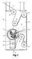
- Figures 1 to 4 show a spraying device for spraying a liquid product onto a paper sheet, comprising a structure 8 in which there are supported mutually parallel guide rollers 6 guiding the path of a moving paper sheet web 2.
- the axes of the guide rollers 6 are not in the same plane, such that between them they define a plurality of sections of the paper sheet web forming different angles with one another.
- a rotary support 7 parallel to the axis of the guide rollers 6 on which there are arranged a plurality of spraying nozzles 1 distributed along the length thereof and connected to a liquid product supply source.
- the rotary support 7 (described in further detail below in relation to Figure 5 ) includes a tubular wall 7a defining an enclosure in which the spraying nozzles are installed.
- the tubular wall 7a has a longitudinal opening 4 facing and aligned with the spraying nozzles 1.
- the spraying device further comprises a pair of side walls 5 perpendicular to the axes of the guide rollers 6 supported in the structure 8. These side walls 5 are configured according to the path of the different sections of the paper sheet web 2 and are separated from one another by a distance according to the width of the paper sheet web 2.
- Two of the guide rollers 6 are arranged adjacent to the tubular wall 7a of the rotary support 7, such that several of the different contiguous sections of the paper sheet web 2, portions of the tubular wall 7a of the rotary support 7 adjacent to the longitudinal opening 4, and the side walls 5 delimit an inner space forming the spray chamber 3.
- Two of the guide rollers 6 are located inside the spray chamber 3. The liquid product is sprayed by the spraying nozzles 1 through the longitudinal opening 4 and into the spray chamber 3.
- Two contiguous sections of the paper sheet web 2 together forming an acute angle containing, including or encompassing the spraying nozzles 1 are defined between one of the guide rollers 6 located inside the spray chamber 3 and two other guide rollers 6.
- the spraying nozzles 1 are directed towards one of the sections of the moving paper sheet web 2 so as to apply the liquid product sprayed thereon.
- the rotary support 7 together with the tubular wall 7a can be rotated with respect to an axis parallel to the axes of the guide rollers 6 so as to regulate the spraying angle of the spraying nozzles 1 with respect to the section of the paper sheet web 2 on which the sprayed liquid product is to be applied.
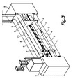
- the side walls 5 are connected to guide rods 9 ( Figure 3 ) supported in the structure 8, such that the side walls are movable in a direction parallel to the axes of the guide rollers 6 and can be fixed in desired positions to adjust the width of the spray chamber 3 to the width of the paper sheet web 2.
- the spraying nozzles 1 are axially movable along the rotary support 7 in a direction parallel to the axes of the guide rollers 6.
- the circuit supplying the liquid product to the spraying nozzles 1 includes a valve arrangement which allows individually opening and closing each of the spraying nozzles 1. So when a paper sheet web 2 is used that is narrower than the maximum allowable width of the device, only those spraying nozzles 1 which are inside the spray chamber 3 will be left active, while the rest will be closed.
- At least one of the guide rollers 6 adjacent to the tubular wall 7a of the rotary support 7 can be moved in a direction perpendicular to its own axis to facilitate access to the spray chamber 3 even when the paper sheet web 2 is installed on the guide rollers 6.
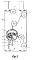
- the spraying device of the present invention further comprises a cleaning chamber 12 provided with a plurality of cleaning nozzles 10 connected to a cleaning liquid supply source.
- This cleaning chamber 12 is located outside the spray chamber 3 and outside the tubular wall 7a of the rotary support 7.
- the rotary support 7 can be rotated to an angular cleaning position ( Figure 2 ) in which the longitudinal opening 4 of the tubular wall 7a is facing the cleaning chamber 12 and the spraying nozzles 1 are facing the cleaning nozzles 10.
- the cleaning liquid can therefore be sprayed by the cleaning nozzles 10 onto the spraying nozzles 1 and other elements housed inside the tubular wall 7a.
- the paper sheet web is not installed on the guide rollers 6.
- the cleaning liquid can also be circulated through the circuit supplying the liquid product to the spraying nozzles 1 in order to clean said circuit and the inside of the spraying nozzles 1, and through a fixed conduit 28 provided with nozzles 29 located inside the tubular wall 7a (described in further detail below in relation to Figure 5 ) in order to clean the inner surfaces of the tubular wall 7a and other elements housed therein at the end of an operation for applying a liquid product on a paper sheet web 2.
- Figure 5 shows in detail one end of the tubular wall 7a of the rotary support 7.
- Each end of the tubular wall is supported and guided in a rotational manner with respect to the structure 8 by a plurality of wheels 13 (only one of which can be seen in Figure 5 ) rolling on a cylindrical outer surface of the tubular wall 7a.
- a motor (not shown) is operatively connected to rotate the tubular wall 7a about its longitudinal axis.
- the inner enclosure of the tubular wall 7a is closed at its ends by end walls 14.
- a main liquid product supply tube 15 and a pressurized air supply tube 16 securely connected to one another by connection members 21 are installed inside the tubular wall 7a.
- Each end of the main liquid product supply tube 15 is surrounded by a jacket 27 going through the corresponding end wall 14 of the tubular wall 7a through a sliding friction bearing 19.
- Each end of the pressurized air supply tube 16 goes through the end wall 14 of the tubular wall 7a through a corresponding sliding friction bearing 20.
- the main liquid product supply tube 15 and the pressurized air supply tube 16 can therefore slide axially with respect to the tubular wall 7a and rotate together with the tubular wall 7a with respect to the axis thereof.
- the outer ends of the main liquid product supply tube 15 and of the pressurized air supply tube 16 are connected to a main liquid product supply source and to a pressurized air supply source (not shown), respectively.
- the main liquid product supply tube 15 has a plurality of connectors 17 distributed along same and the pressurized air supply tube 16 has a plurality of connectors 18 also distributed along same.
- connection members 21 support auxiliary supply tubes 23, 24, each of which also has a plurality of connectors 25, 26 distributed along same.
- auxiliary supply tubes 23, 24 can be connected to respective auxiliary product supply sources (not shown) through respective conduits (not shown) going through the jacket 27 into an annular space between the main liquid product supply tube 15 and the jacket 27.
- connection members 21 have a longitudinal support (not shown) fixed thereto where there are installed a series of sprayer groups (not shown) distributed along the length of the tubular wall 7a.
- Each sprayer group includes one of the spraying nozzles 1 associated with one or more valves, and connecting sleeves connect the mentioned connectors 17, 18, 25, 26 to inlet ports of said one or more valves.
- the liquid product sprayed by the spraying nozzles 1 is therefore a mixture of main liquid product and pressurized air, and optionally other auxiliary products.
- One or more fluid dynamic cylinders 22 are all operatively connected to jointly move the main liquid product supply tube 15, the pressurized air supply tube 16, the auxiliary supply tubes 23, 24 and the connection members 21 in an axial direction with respect to the tubular wall 7a.
- a fixed conduit 28 provided with a plurality of nozzles 29 distributed along same is further installed inside the tubular wall 7a. At least one end of the fixed conduit 28 goes through the end wall 14 through a corresponding hole and is connected to a cleaning liquid supply source.
- the nozzles 29 of the fixed conduit 28 are therefore used to spray cleaning liquid on inner surfaces of the tubular wall 7a and other members housed therein at the end of an operation for applying a liquid product on paper sheet web.
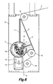
- Figure 6 shows a spraying device for spraying a liquid product onto a paper sheet according to another embodiment of the present invention, which differs from the embodiment described above in relation to Figures 1 to 4 in that only one of the guide rollers 6 is inside the spray chamber 3 and adjacent to the tubular wall 7a of the rotary support 7, such that only one section of the paper sheet web 2 comprised between this guide roller 6 located inside the spray chamber 3 and another guide roller 6 delimits the spray chamber 3.
- the spray chamber 3 is delimited by the mentioned section of the paper sheet web 2, by portions of the tubular wall 7a of the rotary support 7 adjacent to the longitudinal opening 4, by the side walls 5, and by a rear plate 11 facing the section of the paper sheet web 2 and having an end adjacent to the tubular wall 7a of the rotary support 7 and another end adjacent to the section of the paper sheet web 2.
Landscapes
- Paper (AREA)
Abstract
The spraying device for spraying a liquid product onto a paper sheet comprises spraying nozzles (1) connected to a liquid product supply source and arranged in a spray chamber (3) to spray the liquid product onto a moving paper sheet web (2) guided by guide rollers (6), where the spray chamber (3) is delimited in part by the moving paper sheet web (2), and at least one of the guide rollers (6) is located inside the spray chamber (3). In one embodiment, the spraying nozzles (1) are arranged in a rotary support (7) including a tubular wall (7a) with a longitudinal opening (4), and the spray chamber (3) is delimited only by sections of the paper sheet web (2), portions of the tubular wall (7a) adjacent to the longitudinal opening (4), and side walls (5).
Description
- The present invention relates to a spraying device for spraying a liquid product onto a paper sheet useful for applying a coating of liquid product sprayed onto a moving paper sheet web.
- The device of the present invention is useful for creating a barrier coating against fats, oil and water, and/or an anti-scratch coating, and/or a pigmentation coating, and/or a coating of any other surface treatment on a paper sheet web, whereby obtaining a waterproof paper sheet web which can be used, for example, in forming hydrophobic corrugated cardboard, or a paper sheet with other properties and for other uses.
- Document
WO 2013167771 A1 discloses an applicator device for applying a liquid product on a paper sheet comprising a spray chamber with an opening facing the path of a moving paper sheet web. The spray chamber has a front wall, a rear wall, side walls, and a base opposite the opening. A plurality of spraying nozzles is installed inside the spray chamber and said nozzles are connected to a liquid product supply source and oriented so as to direct the sprayed liquid product towards the opening across the spray chamber in order to spray the liquid product onto a surface of the moving paper sheet web. - A drawback of the device described in the cited document
WO 2013167771 A1 is that part of the sprayed liquid product is deposited and accumulated on the inner surfaces of the walls of the spray chamber, making frequent cleaning operations necessary. - Document
WO 0042254 A1 - Document
WO 2006079678 A1 discloses an applicator device for applying a liquid product on a paper sheet including a plurality of spraying nozzles installed such that they are rotational so as to regulate the angle of incidence of the sprayed liquid product with respect to the paper sheet, and a system for adapting the width of the device to the width of the paper sheet. - Document
EP 2146003 A2 describes a device for applying a liquid product curtain as a coating on a paper sheet including a suction nozzle for absorbing part of the liquid product that is sprayed and not deposited on the paper sheet. - Other examples of apparatuses for applying a liquid product on a paper sheet are described in documents
DE 102008040419 A1 andWO 2005040497 A1 . - The present invention contributes to mitigate the foregoing and other drawbacks by providing a spraying device for spraying a liquid product onto a paper sheet comprising a spray chamber delimited to a large extent by a moving paper sheet web guided by parallel guide rollers, and a plurality of spraying nozzles connected to a liquid product supply source and arranged inside said spray chamber to spray said liquid product onto said moving paper sheet web, where at least one of said guide rollers is located inside the spray chamber.
- Preferably, the spray chamber is delimited at least in part by two contiguous sections of the paper sheet web which are defined between one of the guide rollers located inside the spray chamber and two other guide rollers adjacent to the former. The two contiguous sections of the paper sheet web therefore together form an angle containing, including or encompassing the spraying nozzles.
- Optionally, the guide rollers can define more than two sections of the paper sheet web delimiting the spray chamber, with two or more guide rollers located inside the spray chamber. The spraying nozzles are preferably arranged so as to direct the sprayed liquid product towards a single section of the paper sheet web.
- The plurality of sections of the paper sheet web delimiting the spray chamber contribute to minimizing the area of other surfaces of the spray chamber exposed to the liquid product sprayed by the spraying nozzles, and therefore the drawback of the unwanted deposition and accumulation of liquid product on surfaces other than the paper sheet web is minimized.
- Regardless of the number of sections of the paper sheet web in the spray chamber, the spray chamber is further delimited by side walls perpendicular to the axes of the guide rollers. These side walls are movable along guides associated with a structure of the device in a direction parallel to the axes of the guide rollers and can be fixed in desired positions along said guides to adjust the width of the spray chamber to the width of the paper sheet web.
- In one embodiment, the spraying nozzles are arranged in a rotary support which can be rotated with respect to an axis parallel to the axes of the guide rollers to regulate the spraying angle of the spraying nozzles, i.e., the angle of the spraying nozzles with respect to the section of the paper sheet web towards which they are directed. Preferably, this rotary support includes a tubular wall defining an enclosure in which the spraying nozzles are installed. The tubular wall rotates together with the rotary support and has at least one longitudinal opening through which the liquid product is sprayed into the spray chamber by the spraying nozzles.
- Generally, the spray chamber is also delimited in part by portions of the tubular wall of the rotary support adjacent to its longitudinal opening. In one embodiment, at least two of the guide rollers are arranged adjacent to the tubular wall of the rotary support, such that the spray chamber is delimited by the paper sheet web, by the portions of the tubular wall adjacent to its longitudinal opening, and by the side walls.
- Preferably, the spraying nozzles are axially movable along guides associated with the rotary support in a direction parallel to the axes of the guide rollers and can be fixed in a selected position along the rotary support to center or adjust the position of the spraying nozzles with respect to the paper sheet web. A valve arrangement also allows individually opening and closing each of the spraying nozzles to adjust the number of active spraying nozzles to the width of the paper sheet web being treated, in each case.
- In one embodiment, one or more of the guide rollers can be moved in a direction perpendicular to its own axis to facilitate access to the spray chamber, even when the paper sheet web is installed on the guide rollers.
- In one embodiment, the spraying device further comprises a cleaning chamber located outside the spray chamber and outside the tubular wall of the rotary support. This cleaning chamber internally has a plurality of cleaning nozzles connected to a cleaning liquid supply source, said cleaning liquid being water or another solvent suitable for dissolving the liquid product used. The rotary support can be rotated to an angular cleaning position in which the longitudinal opening of the tubular wall of the rotary support is facing the cleaning chamber and the spraying nozzles are facing said cleaning nozzles.
- Additionally, the cleaning liquid can also be circulated through the circuit supplying the liquid product to the spraying nozzles in order to clean said circuit and the inside of the spraying nozzles at the end of an operation for applying a liquid product on a paper sheet web.
- The above and other features and advantages will be better understood from the following detailed description of exemplary embodiments, which are merely illustrative and not limitative, with reference to the accompanying drawings, in which:
-
Figure 1 is a cross-sectional view of a spraying device for spraying a liquid product onto a paper sheet according to an embodiment of the present invention, in a working position; -
Figure 2 is a cross-sectional view of the spraying device ofFigure 1 in a cleaning position; -
Figure 3 is a front perspective view of the spraying device ofFigure 1 ; -
Figure 4 is a rear perspective view of the spraying device ofFigure 1 ; -
Figure 5 is a sectioned partial view of a rotary support with a tubular wall included in the spraying device ofFigure 1 ; and -
Figure 6 is a cross-section view of a spraying device for spraying a liquid product onto a paper sheet according to another embodiment of the present invention. -
Figures 1 to 4 show a spraying device for spraying a liquid product onto a paper sheet, comprising astructure 8 in which there are supported mutuallyparallel guide rollers 6 guiding the path of a movingpaper sheet web 2. The axes of theguide rollers 6 are not in the same plane, such that between them they define a plurality of sections of the paper sheet web forming different angles with one another. - There is further supported in a
structure 8 of the spraying device arotary support 7 parallel to the axis of theguide rollers 6 on which there are arranged a plurality of sprayingnozzles 1 distributed along the length thereof and connected to a liquid product supply source. The rotary support 7 (described in further detail below in relation toFigure 5 ) includes atubular wall 7a defining an enclosure in which the spraying nozzles are installed. Thetubular wall 7a has alongitudinal opening 4 facing and aligned with the sprayingnozzles 1. - The spraying device further comprises a pair of
side walls 5 perpendicular to the axes of theguide rollers 6 supported in thestructure 8. Theseside walls 5 are configured according to the path of the different sections of thepaper sheet web 2 and are separated from one another by a distance according to the width of thepaper sheet web 2. - Two of the
guide rollers 6 are arranged adjacent to thetubular wall 7a of therotary support 7, such that several of the different contiguous sections of thepaper sheet web 2, portions of thetubular wall 7a of therotary support 7 adjacent to thelongitudinal opening 4, and theside walls 5 delimit an inner space forming thespray chamber 3. Two of theguide rollers 6 are located inside thespray chamber 3. The liquid product is sprayed by the sprayingnozzles 1 through thelongitudinal opening 4 and into thespray chamber 3. - Two contiguous sections of the
paper sheet web 2 together forming an acute angle containing, including or encompassing the sprayingnozzles 1 are defined between one of theguide rollers 6 located inside thespray chamber 3 and twoother guide rollers 6. - The spraying
nozzles 1 are directed towards one of the sections of the movingpaper sheet web 2 so as to apply the liquid product sprayed thereon. Therotary support 7 together with thetubular wall 7a can be rotated with respect to an axis parallel to the axes of theguide rollers 6 so as to regulate the spraying angle of the sprayingnozzles 1 with respect to the section of thepaper sheet web 2 on which the sprayed liquid product is to be applied. - The
side walls 5 are connected to guide rods 9 (Figure 3 ) supported in thestructure 8, such that the side walls are movable in a direction parallel to the axes of theguide rollers 6 and can be fixed in desired positions to adjust the width of thespray chamber 3 to the width of thepaper sheet web 2. The sprayingnozzles 1 are axially movable along therotary support 7 in a direction parallel to the axes of theguide rollers 6. - The circuit supplying the liquid product to the spraying
nozzles 1 includes a valve arrangement which allows individually opening and closing each of thespraying nozzles 1. So when apaper sheet web 2 is used that is narrower than the maximum allowable width of the device, only those sprayingnozzles 1 which are inside thespray chamber 3 will be left active, while the rest will be closed. - Additionally, at least one of the
guide rollers 6 adjacent to thetubular wall 7a of therotary support 7 can be moved in a direction perpendicular to its own axis to facilitate access to thespray chamber 3 even when thepaper sheet web 2 is installed on theguide rollers 6. - The spraying device of the present invention further comprises a
cleaning chamber 12 provided with a plurality ofcleaning nozzles 10 connected to a cleaning liquid supply source. Thiscleaning chamber 12 is located outside thespray chamber 3 and outside thetubular wall 7a of therotary support 7. Therotary support 7 can be rotated to an angular cleaning position (Figure 2 ) in which thelongitudinal opening 4 of thetubular wall 7a is facing thecleaning chamber 12 and the sprayingnozzles 1 are facing thecleaning nozzles 10. The cleaning liquid can therefore be sprayed by thecleaning nozzles 10 onto the sprayingnozzles 1 and other elements housed inside thetubular wall 7a. InFigure 2 , the paper sheet web is not installed on theguide rollers 6. - During a cleaning operation, the cleaning liquid can also be circulated through the circuit supplying the liquid product to the
spraying nozzles 1 in order to clean said circuit and the inside of the sprayingnozzles 1, and through a fixedconduit 28 provided withnozzles 29 located inside thetubular wall 7a (described in further detail below in relation toFigure 5 ) in order to clean the inner surfaces of thetubular wall 7a and other elements housed therein at the end of an operation for applying a liquid product on apaper sheet web 2. -
Figure 5 shows in detail one end of thetubular wall 7a of therotary support 7. Each end of the tubular wall is supported and guided in a rotational manner with respect to thestructure 8 by a plurality of wheels 13 (only one of which can be seen inFigure 5 ) rolling on a cylindrical outer surface of thetubular wall 7a. Optionally, a motor (not shown) is operatively connected to rotate thetubular wall 7a about its longitudinal axis. - The inner enclosure of the
tubular wall 7a is closed at its ends byend walls 14. A main liquidproduct supply tube 15 and a pressurizedair supply tube 16 securely connected to one another byconnection members 21 are installed inside thetubular wall 7a. Each end of the main liquidproduct supply tube 15 is surrounded by ajacket 27 going through thecorresponding end wall 14 of thetubular wall 7a through a sliding friction bearing 19. Each end of the pressurizedair supply tube 16 goes through theend wall 14 of thetubular wall 7a through a corresponding sliding friction bearing 20. The main liquidproduct supply tube 15 and the pressurizedair supply tube 16 can therefore slide axially with respect to thetubular wall 7a and rotate together with thetubular wall 7a with respect to the axis thereof. - The outer ends of the main liquid
product supply tube 15 and of the pressurizedair supply tube 16 are connected to a main liquid product supply source and to a pressurized air supply source (not shown), respectively. Inside thetubular wall 7a, the main liquidproduct supply tube 15 has a plurality ofconnectors 17 distributed along same and the pressurizedair supply tube 16 has a plurality ofconnectors 18 also distributed along same. - The
connection members 21 supportauxiliary supply tubes connectors auxiliary supply tubes jacket 27 into an annular space between the main liquidproduct supply tube 15 and thejacket 27. - The
connection members 21 have a longitudinal support (not shown) fixed thereto where there are installed a series of sprayer groups (not shown) distributed along the length of thetubular wall 7a. Each sprayer group includes one of the sprayingnozzles 1 associated with one or more valves, and connecting sleeves connect the mentionedconnectors nozzles 1 is therefore a mixture of main liquid product and pressurized air, and optionally other auxiliary products. - One or more fluid
dynamic cylinders 22 are all operatively connected to jointly move the main liquidproduct supply tube 15, the pressurizedair supply tube 16, theauxiliary supply tubes connection members 21 in an axial direction with respect to thetubular wall 7a. - A fixed
conduit 28 provided with a plurality ofnozzles 29 distributed along same is further installed inside thetubular wall 7a. At least one end of the fixedconduit 28 goes through theend wall 14 through a corresponding hole and is connected to a cleaning liquid supply source. Thenozzles 29 of the fixedconduit 28 are therefore used to spray cleaning liquid on inner surfaces of thetubular wall 7a and other members housed therein at the end of an operation for applying a liquid product on paper sheet web. -
Figure 6 shows a spraying device for spraying a liquid product onto a paper sheet according to another embodiment of the present invention, which differs from the embodiment described above in relation toFigures 1 to 4 in that only one of theguide rollers 6 is inside thespray chamber 3 and adjacent to thetubular wall 7a of therotary support 7, such that only one section of thepaper sheet web 2 comprised between thisguide roller 6 located inside thespray chamber 3 and anotherguide roller 6 delimits thespray chamber 3. - In this embodiment shown in
Figure 6 , thespray chamber 3 is delimited by the mentioned section of thepaper sheet web 2, by portions of thetubular wall 7a of therotary support 7 adjacent to thelongitudinal opening 4, by theside walls 5, and by arear plate 11 facing the section of thepaper sheet web 2 and having an end adjacent to thetubular wall 7a of therotary support 7 and another end adjacent to the section of thepaper sheet web 2. - The scope of the present invention is defined in the attached claims.
Claims (11)
- A spraying device for spraying a liquid product onto a paper sheet, comprising a spray chamber (3) delimited at least in part by a moving paper sheet web (2) guided by guide rollers (6), and a plurality of spraying nozzles (1) connected to a liquid product supply source and arranged inside said spray chamber (3) to spray said liquid product onto said moving paper sheet web (2), characterized in that at least one of said guide rollers (6) is located inside the spray chamber (3).
- The spraying device for spraying a liquid product onto a paper sheet according to claim 1, characterized in that the spray chamber (3) is delimited at least in part by two contiguous sections of the paper sheet web (2) which are defined between said at least one of the guide rollers (6) located inside the spray chamber (3) and two other guide rollers (6).
- The spraying device for spraying a liquid product onto a paper sheet according to claim 1 or 2, characterized in that said two contiguous sections of the paper sheet web together form an angle containing, including or encompassing the spraying nozzles.
- The spraying device for spraying a liquid product onto a paper sheet according to claim 1, 2 or 3, characterized in that the spray chamber (3) is further delimited by side walls (5) perpendicular to the axes of the guide rollers (6), and said side walls (5) are movable in a direction parallel to the axes of the guide rollers (6) to adjust the width of the spray chamber (3) to the width of the paper sheet web (2).
- The spraying device for spraying a liquid product onto a paper sheet according to any one of the preceding claims, characterized in that said spraying nozzles (1) are arranged in a rotary support (7) which can be rotated with respect to an axis parallel to the axes of the guide rollers (6) to regulate the spraying angle of the spraying nozzles (1).
- The spraying device for spraying a liquid product onto a paper sheet according to claim 5, characterized in that said rotary support (7) includes a tubular wall (7a) defining an enclosure in which the spraying nozzles are installed, and said tubular wall (7a) has at least one longitudinal opening (4) through which the liquid product is sprayed into the spray chamber (3) by the spraying nozzles (1).
- The spraying device for spraying a liquid product onto a paper sheet according to claim 6, characterized in that the spray chamber (3) is delimited in part by said tubular wall (7a) of the rotary support (7).
- The spraying device for spraying a liquid product onto a paper sheet according to claim 7, characterized in that at least two of the guide rollers (6) are arranged adjacent to the tubular wall (7a) of the rotary support (7), such that the spray chamber (3) is delimited by the paper sheet web (2), the tubular wall (7a) of the rotary support (7), and the side walls (5).
- The spraying device for spraying a liquid product onto a paper sheet according to claim 8, characterized in that at least one of the guide rollers (6) adjacent to the tubular wall (7a) of the rotary support (7) can be moved in a direction perpendicular to its own axis to facilitate access to the spray chamber (3).
- The spraying device for spraying a liquid product onto a paper sheet according to claim 5 or 6, characterized in that said spraying nozzles (1) are axially movable along the rotary support (7) in a direction parallel to the axes of the guide rollers (6).
- The spraying device for spraying a liquid product onto a paper sheet according to claim 6, characterized by comprising a cleaning chamber (12) provided with a plurality of cleaning nozzles (10) connected to a cleaning liquid supply source, where said cleaning chamber (12) is located outside the spray chamber (3) and outside the tubular wall (7a) of the rotary support (7), and where said rotary support (7) can be rotated to an angular cleaning position in which the longitudinal opening (4) of the tubular wall (7a) is facing the cleaning chamber (12) and the spraying nozzles (1) are facing said cleaning nozzles (10).
Priority Applications (3)
| Application Number | Priority Date | Filing Date | Title |
|---|---|---|---|
| EP14380022.5A EP2985385A1 (en) | 2014-08-11 | 2014-08-11 | Spraying device for spraying a liquid product onto paper sheet |
| EP15002387.7A EP2985386B1 (en) | 2014-08-11 | 2015-08-11 | Spraying device for spraying a liquid product onto a paper web |
| ES15002387.7T ES2632140T3 (en) | 2014-08-11 | 2015-08-11 | Spray device for spraying a liquid product on a paper strip |
Applications Claiming Priority (1)
| Application Number | Priority Date | Filing Date | Title |
|---|---|---|---|
| EP14380022.5A EP2985385A1 (en) | 2014-08-11 | 2014-08-11 | Spraying device for spraying a liquid product onto paper sheet |
Publications (1)
| Publication Number | Publication Date |
|---|---|
| EP2985385A1 true EP2985385A1 (en) | 2016-02-17 |
Family
ID=51542305
Family Applications (2)
| Application Number | Title | Priority Date | Filing Date |
|---|---|---|---|
| EP14380022.5A Withdrawn EP2985385A1 (en) | 2014-08-11 | 2014-08-11 | Spraying device for spraying a liquid product onto paper sheet |
| EP15002387.7A Active EP2985386B1 (en) | 2014-08-11 | 2015-08-11 | Spraying device for spraying a liquid product onto a paper web |
Family Applications After (1)
| Application Number | Title | Priority Date | Filing Date |
|---|---|---|---|
| EP15002387.7A Active EP2985386B1 (en) | 2014-08-11 | 2015-08-11 | Spraying device for spraying a liquid product onto a paper web |
Country Status (2)
| Country | Link |
|---|---|
| EP (2) | EP2985385A1 (en) |
| ES (1) | ES2632140T3 (en) |
Cited By (3)
| Publication number | Priority date | Publication date | Assignee | Title |
|---|---|---|---|---|
| WO2018102846A1 (en) * | 2016-12-07 | 2018-06-14 | Pixelrunner GmbH | Device for printing images on floor surfaces |
| CN111570149A (en) * | 2020-06-05 | 2020-08-25 | 程祥冬 | Environment-friendly three-way pipe machining device |
| CN113802410A (en) * | 2021-08-05 | 2021-12-17 | 镇江欣茂纸品贸易有限公司 | Coated paper surface film coating device and operation method thereof |
Families Citing this family (3)
| Publication number | Priority date | Publication date | Assignee | Title |
|---|---|---|---|---|
| CN108355868B (en) * | 2018-01-24 | 2019-12-20 | 江苏盐邦泵业制造有限公司 | Water conservancy pipeline outer wall mopping device |
| CN112676055B (en) * | 2020-11-30 | 2022-04-08 | 江苏金狮堂视觉科技有限公司 | Pipe fitting paint spraying device for architectural decoration engineering and using method thereof |
| CN116334953B (en) * | 2023-05-22 | 2023-08-01 | 青州博睿包装科技有限公司 | Double-sided laminating machine for laminated paper |
Citations (12)
| Publication number | Priority date | Publication date | Assignee | Title |
|---|---|---|---|---|
| US5780109A (en) * | 1997-01-21 | 1998-07-14 | Minnesota Mining And Manufacturing Company | Die edge cleaning system |
| WO2000042254A1 (en) | 1999-01-18 | 2000-07-20 | Metso Paper, Inc. | Spray-coating method and spray-coater |
| WO2002072953A1 (en) * | 2001-03-13 | 2002-09-19 | Metso Paper, Inc. | Assembly for treating a web of paper or paperboard |
| WO2005040497A1 (en) | 2003-10-28 | 2005-05-06 | Metso Paper, Inc. | Spray coating unit and method of spray coating |
| WO2006079678A1 (en) | 2005-01-27 | 2006-08-03 | Metso Paper, Inc. | Apparatus for regulating the application width of a slide-fed curtain coater |
| DE102008021541A1 (en) * | 2007-05-14 | 2008-11-20 | Metso Paper, Inc. | Procedure for the treatment of paper- or cardboard web or a corresponding fiber web, comprises applying a treatment medium on a surface of the web by guiding the web through an inlet slot in an application chamber |
| EP2146003A2 (en) | 2008-07-15 | 2010-01-20 | Voith Patent GmbH | Curtain application device |
| DE102008040419A1 (en) | 2008-07-15 | 2010-01-21 | Voith Patent Gmbh | Curtain-coating unit for coating paper, cardboard or other fiber web with fluid to pasty coating medium in the form of single or multilayered curtain, comprises a discharge nozzle, a drip pan and/or an air barrier removing unit |
| DE102011017672A1 (en) * | 2010-04-29 | 2011-11-03 | Metso Paper, Inc. | Plant for treating fibrous web, comprises spraying boxes having a spraying chamber and a spraying nozzle for spraying a treatment liquid, nips and means for pressing the fibrous web, first spraying boxes, and a limiting device |
| JP2012000476A (en) * | 2011-08-04 | 2012-01-05 | Oji Nepia Co Ltd | Method of manufacturing lotion paper |
| WO2013167771A1 (en) | 2012-05-07 | 2013-11-14 | Xavier Blanch Andreu | Device for applying a liquid product to a sheet of paper |
| EP2735648A1 (en) * | 2012-11-22 | 2014-05-28 | Valmet Technologies, Inc. | Device for treating a fiber web |
-
2014
- 2014-08-11 EP EP14380022.5A patent/EP2985385A1/en not_active Withdrawn
-
2015
- 2015-08-11 EP EP15002387.7A patent/EP2985386B1/en active Active
- 2015-08-11 ES ES15002387.7T patent/ES2632140T3/en active Active
Patent Citations (12)
| Publication number | Priority date | Publication date | Assignee | Title |
|---|---|---|---|---|
| US5780109A (en) * | 1997-01-21 | 1998-07-14 | Minnesota Mining And Manufacturing Company | Die edge cleaning system |
| WO2000042254A1 (en) | 1999-01-18 | 2000-07-20 | Metso Paper, Inc. | Spray-coating method and spray-coater |
| WO2002072953A1 (en) * | 2001-03-13 | 2002-09-19 | Metso Paper, Inc. | Assembly for treating a web of paper or paperboard |
| WO2005040497A1 (en) | 2003-10-28 | 2005-05-06 | Metso Paper, Inc. | Spray coating unit and method of spray coating |
| WO2006079678A1 (en) | 2005-01-27 | 2006-08-03 | Metso Paper, Inc. | Apparatus for regulating the application width of a slide-fed curtain coater |
| DE102008021541A1 (en) * | 2007-05-14 | 2008-11-20 | Metso Paper, Inc. | Procedure for the treatment of paper- or cardboard web or a corresponding fiber web, comprises applying a treatment medium on a surface of the web by guiding the web through an inlet slot in an application chamber |
| EP2146003A2 (en) | 2008-07-15 | 2010-01-20 | Voith Patent GmbH | Curtain application device |
| DE102008040419A1 (en) | 2008-07-15 | 2010-01-21 | Voith Patent Gmbh | Curtain-coating unit for coating paper, cardboard or other fiber web with fluid to pasty coating medium in the form of single or multilayered curtain, comprises a discharge nozzle, a drip pan and/or an air barrier removing unit |
| DE102011017672A1 (en) * | 2010-04-29 | 2011-11-03 | Metso Paper, Inc. | Plant for treating fibrous web, comprises spraying boxes having a spraying chamber and a spraying nozzle for spraying a treatment liquid, nips and means for pressing the fibrous web, first spraying boxes, and a limiting device |
| JP2012000476A (en) * | 2011-08-04 | 2012-01-05 | Oji Nepia Co Ltd | Method of manufacturing lotion paper |
| WO2013167771A1 (en) | 2012-05-07 | 2013-11-14 | Xavier Blanch Andreu | Device for applying a liquid product to a sheet of paper |
| EP2735648A1 (en) * | 2012-11-22 | 2014-05-28 | Valmet Technologies, Inc. | Device for treating a fiber web |
Cited By (5)
| Publication number | Priority date | Publication date | Assignee | Title |
|---|---|---|---|---|
| WO2018102846A1 (en) * | 2016-12-07 | 2018-06-14 | Pixelrunner GmbH | Device for printing images on floor surfaces |
| CN110325287A (en) * | 2016-12-07 | 2019-10-11 | 像素酷跑有限公司 | A kind of device for print image on the ground |
| US11090672B2 (en) | 2016-12-07 | 2021-08-17 | Pixelrunner GmbH | Device for printing images on floor surfaces |
| CN111570149A (en) * | 2020-06-05 | 2020-08-25 | 程祥冬 | Environment-friendly three-way pipe machining device |
| CN113802410A (en) * | 2021-08-05 | 2021-12-17 | 镇江欣茂纸品贸易有限公司 | Coated paper surface film coating device and operation method thereof |
Also Published As
| Publication number | Publication date |
|---|---|
| EP2985386B1 (en) | 2017-04-05 |
| EP2985386A1 (en) | 2016-02-17 |
| ES2632140T3 (en) | 2017-09-11 |
Similar Documents
| Publication | Publication Date | Title |
|---|---|---|
| EP2985385A1 (en) | Spraying device for spraying a liquid product onto paper sheet | |
| EP3096887B1 (en) | Nozzle assembly with self-cleaning face | |
| TR201808864T4 (en) | Lubrication with spray nozzles with multiple oil inlet openings. | |
| CN110944758A (en) | Barrel coating device | |
| EP2514698B2 (en) | Tube in a rotating folding roll | |
| KR101487325B1 (en) | Painting Apparatus for Pipe | |
| EP2808087A1 (en) | Device for treating a fibre web | |
| FI66448C (en) | BELAEGGNINGSANORDNING FOER BANA | |
| CN209791870U (en) | Double-roller edge sealing strip UV gloss oil continuous coating equipment | |
| FI119444B (en) | Coating plant for a paper / board path | |
| EP2193917A1 (en) | Spray dampener | |
| EP2991772A1 (en) | Changeover device for coating media and coating system for coating objects | |
| EP3260802B1 (en) | Nozzle for a device for contact-free treatment of a running fiber web | |
| EP2082811A3 (en) | Multiple curtain painting device | |
| FI77070C (en) | shower fittings | |
| KR20050095519A (en) | Rotary stretching arrangement for wrinkle-free guidance of band material | |
| EP1535668A3 (en) | Coating device for several coatings disposed side by side | |
| EP2647760B1 (en) | Device for treating a fiber web | |
| KR101979359B1 (en) | Coater device set | |
| WO2011072895A1 (en) | Dryer | |
| CA2926412C (en) | Remote nozzle deckle system | |
| EP1391554A2 (en) | Coating apparatus | |
| EP2784217A1 (en) | Arrangement in a fiber web production line and method in a fiber web production line | |
| US20150246789A1 (en) | Hose reel assembly | |
| IT202100011126A1 (en) | REDUCED ENCLOSURE GROUP FOR THE ROTATIONAL SUPPORT OF A ROTARY CAROUSEL FOR LEATHER PAINTING, AS WELL AS A PAINTING BOOTH WHICH INCLUDES THIS UNIT AND A LEATHER FINISHING LINE WHICH INCLUDES THIS PAINTING BOOTH |
Legal Events
| Date | Code | Title | Description |
|---|---|---|---|
| PUAI | Public reference made under article 153(3) epc to a published international application that has entered the european phase |
Free format text: ORIGINAL CODE: 0009012 |
|
| AK | Designated contracting states |
Kind code of ref document: A1 Designated state(s): AL AT BE BG CH CY CZ DE DK EE ES FI FR GB GR HR HU IE IS IT LI LT LU LV MC MK MT NL NO PL PT RO RS SE SI SK SM TR |
|
| AX | Request for extension of the european patent |
Extension state: BA ME |
|
| STAA | Information on the status of an ep patent application or granted ep patent |
Free format text: STATUS: THE APPLICATION IS DEEMED TO BE WITHDRAWN |
|
| 18D | Application deemed to be withdrawn |
Effective date: 20160818 |
|
| P01 | Opt-out of the competence of the unified patent court (upc) registered |
Effective date: 20230418 |