EP2984240B1 - Verfahren zum betrieb einer vibrationsrammanordnung - Google Patents
Verfahren zum betrieb einer vibrationsrammanordnung Download PDFInfo
- Publication number
- EP2984240B1 EP2984240B1 EP14717670.5A EP14717670A EP2984240B1 EP 2984240 B1 EP2984240 B1 EP 2984240B1 EP 14717670 A EP14717670 A EP 14717670A EP 2984240 B1 EP2984240 B1 EP 2984240B1
- Authority
- EP
- European Patent Office
- Prior art keywords
- combustion engine
- internal combustion
- hydraulic
- vibrator
- operating state
- Prior art date
- Legal status (The legal status is an assumption and is not a legal conclusion. Google has not performed a legal analysis and makes no representation as to the accuracy of the status listed.)
- Active
Links
Images

Classifications
-
- E—FIXED CONSTRUCTIONS
- E02—HYDRAULIC ENGINEERING; FOUNDATIONS; SOIL SHIFTING
- E02D—FOUNDATIONS; EXCAVATIONS; EMBANKMENTS; UNDERGROUND OR UNDERWATER STRUCTURES
- E02D7/00—Methods or apparatus for placing sheet pile bulkheads, piles, mouldpipes, or other moulds
- E02D7/18—Placing by vibrating
-
- F—MECHANICAL ENGINEERING; LIGHTING; HEATING; WEAPONS; BLASTING
- F15—FLUID-PRESSURE ACTUATORS; HYDRAULICS OR PNEUMATICS IN GENERAL
- F15B—SYSTEMS ACTING BY MEANS OF FLUIDS IN GENERAL; FLUID-PRESSURE ACTUATORS, e.g. SERVOMOTORS; DETAILS OF FLUID-PRESSURE SYSTEMS, NOT OTHERWISE PROVIDED FOR
- F15B9/00—Servomotors with follow-up action, e.g. obtained by feed-back control, i.e. in which the position of the actuated member conforms with that of the controlling member
- F15B9/14—Servomotors with follow-up action, e.g. obtained by feed-back control, i.e. in which the position of the actuated member conforms with that of the controlling member with rotary servomotors
-
- F—MECHANICAL ENGINEERING; LIGHTING; HEATING; WEAPONS; BLASTING
- F02—COMBUSTION ENGINES; HOT-GAS OR COMBUSTION-PRODUCT ENGINE PLANTS
- F02D—CONTROLLING COMBUSTION ENGINES
- F02D17/00—Controlling engines by cutting out individual cylinders; Rendering engines inoperative or idling
- F02D17/04—Controlling engines by cutting out individual cylinders; Rendering engines inoperative or idling rendering engines inoperative or idling, e.g. caused by abnormal conditions
-
- F—MECHANICAL ENGINEERING; LIGHTING; HEATING; WEAPONS; BLASTING
- F02—COMBUSTION ENGINES; HOT-GAS OR COMBUSTION-PRODUCT ENGINE PLANTS
- F02D—CONTROLLING COMBUSTION ENGINES
- F02D29/00—Controlling engines, such controlling being peculiar to the devices driven thereby, the devices being other than parts or accessories essential to engine operation, e.g. controlling of engines by signals external thereto
- F02D29/04—Controlling engines, such controlling being peculiar to the devices driven thereby, the devices being other than parts or accessories essential to engine operation, e.g. controlling of engines by signals external thereto peculiar to engines driving pumps
-
- F—MECHANICAL ENGINEERING; LIGHTING; HEATING; WEAPONS; BLASTING
- F15—FLUID-PRESSURE ACTUATORS; HYDRAULICS OR PNEUMATICS IN GENERAL
- F15B—SYSTEMS ACTING BY MEANS OF FLUIDS IN GENERAL; FLUID-PRESSURE ACTUATORS, e.g. SERVOMOTORS; DETAILS OF FLUID-PRESSURE SYSTEMS, NOT OTHERWISE PROVIDED FOR
- F15B15/00—Fluid-actuated devices for displacing a member from one position to another; Gearing associated therewith
- F15B15/18—Combined units comprising both motor and pump
Definitions
- the invention relates to a method for operating a vibration ram arrangement
- a vibration ram arrangement comprising a hydraulic unit with an internal combustion engine, in particular a diesel engine, and a hydraulic pump driven by the internal combustion engine, a vibrator connected to the hydraulic unit in a hydraulic circuit, the rotatably mounted imbalances and at least one hydraulic motor driving the imbalances has, connected to the vibrator hydraulic tensioning device for a pile and a control with the fluid flow through the at least one hydraulic motor for switching on and off of the vibrator can be activated and deactivated and with which the hydraulic tensioning device can be closed and opened.
- a vibration ram arrangement from which the invention proceeds, is known, for example, from the brochure "Müller-Vibrators, The Perfect Solution for Ramming and Pulling", ThyssenKrupp GfT Bautechnik GmbH 5/2011.
- EP 2 014 835 A1 Another example of a vibratory ram assembly whose unbalance is driven by a hydraulic fluid flow is EP 2 014 835 A1 refer to.
- the vibration ramming is based on the principle of putting the soil in a quasi-liquid state. This is achieved by vibrating the pile when hitting the ground. The skin friction of the material to be collected is significantly reduced by the swing and thereby becomes a rapid penetration progress allows.
- the oscillation frequency may be, for example, between 10 Hz and 60 Hz, in particular between 30 Hz and 50 Hz.
- Typical pile goods are, in addition to sheet piling profiles, piles, Planks and pipes for foundation structures of structures and stationary technical installations.
- the engine may be stopped by an operator, that is, turned off.
- the internal combustion engine continues to run during idle periods but at standstill.
- a stop of the internal combustion engine during breaks is often not taken into consideration by an operator for several reasons, because the operator is unaware that the internal combustion engine is still running due to the physical separation of the vibrator and the hydraulic unit and the ambient noise present on a construction site. In addition, the operator is often busy with other tasks than operating the vibratory rammer assembly during breaks.
- the invention has for its object to provide a method for operating a vibrating ram assembly, which allows a cost reduction without sacrificing comfort and reliability. Furthermore, a vibration ram arrangement is to be specified, which enables the implementation of the method.
- the object of the invention and solution of the problem are a method according to claim 1 and a vibration rack assembly according to claim 8.
- the invention provides that in a break in a deactivated vibrator, the controller at least queries an operating state value and automatically stops the engine when the operating state value corresponds to a default value and that the control at a user signal to continue the Vibrationsramm fleecees the combustion engine starts automatically.
- the stopping of the internal combustion engine takes place not only taking into account the activation state of the vibrator, but additionally taking into account a specific for the vibration ram assembly operating state value, just by this additional query a high degree of comfort and reliability can be guaranteed.
- the invention is based on the finding that the internal combustion engine often runs for a longer time without load in the idle gas than in the actual vibration ramming operation under load.
- the proportion of time in which the internal combustion engine runs under load can amount, for example, to only 10% to 20% of the total operating time of the hydraulic aggregate.
- the state of operation of the clamping device is interrogated as the operating state value, the internal combustion engine not being stopped when the clamping device is closed. If, on the other hand, the tensioning device is open, no driving in of the driven load is possible, so that then the internal combustion engine can be stopped, if there are no further boundary conditions that preclude stopping the internal combustion engine.
- a plurality of different operating state values can be interrogated and evaluated in order to determine whether a stop of the internal combustion engine is advantageous.
- the circuit is usually set up so that the tensioner can only be opened when the vibrator is deactivated. Such a control is easily possible because the tensioning device and the vibrator can be acted upon in parallel by the hydraulic unit via separate circuits or connections with hydraulic oil.
- a stop of the internal combustion engine can also take place with a closed clamping device, as long as the vibrator is deactivated and it is ensured that the clamping device remains closed. While the drive of the vibrator requires a continuous volume flow through the hydraulic motor, preferably a static clamping pressure is built up in the clamping device and held so that it is then not necessary to refill hydraulic oil with the hydraulic unit for keeping the clamping device closed.
- the deactivated state of the vibrator may result from a corresponding user-selected setting on the controller.
- the state of the vibrator can also be monitored with a speed or frequency sensor, in which case the signal of this sensor is considered as an operating state value in the context of the invention.
- At least one clamping pressure of the clamping device is interrogated as the operating state value, wherein the internal combustion engine is stopped when, in a closed clamping device, the clamping pressure is greater than a minimum pressure.
- the clamping pressure can be interrogated continuously, with the internal combustion engine starting automatically when the clamping pressure is less than the minimum pressure.
- a greater threshold value for the clamping pressure than for the automatic starting can be provided for stopping the internal combustion engine in order to avoid too frequent stopping and starting of the internal combustion engine.
- the controller changes in a safety mode, if after stopping the engine re-starting due to a drop in the clamping pressure within a predetermined time interval, wherein in the safety mode no renewed shutdown of the engine he follows.
- the internal combustion engine then runs through at least independently of the activation state of the vibrator, but in the case of an open clamping device, the internal combustion engine can continue to stop according to the first variant of the method.
- a particularly high degree of operational reliability can be achieved. It is also expedient to indicate to a user by means of a suitable display device an error message or a malfunction, so that this can make a check of the clamping device and the associated hydraulic circuit. Especially with a leak there is a risk of contamination of the environment, which can be prevented by the display of the malfunction. If the time between stopping and starting the internal combustion engine is particularly short, this can be an indication of a massive disturbance, so that then optionally the controller can be set so that the vibrating ram assembly is completely turned off until a fault is eliminated or at least the controller is reset.
- the internal combustion engine can only be stopped with a time delay, so that the internal combustion engine is not stopped in only short operating pauses.
- the internal combustion engine is expediently started when a user makes an input "closing the clamping device" on the control.
- the second variant of the internal combustion engine is then conveniently started when a user makes an input to the controller "vibrator ON".
- the internal combustion engine and the hydraulic oil have a suitable operating temperature, the internal combustion engine can usually be started directly, so that a user usually perceives no difference at all and no impairment compared to the known from the prior art method, in which the internal combustion engine idling continues without load.
- an engine oil temperature of the internal combustion engine can be queried as an additional operating state value, wherein the internal combustion engine is not stopped when the engine oil temperature is below an associated minimum temperature.
- the invention also provides a vibrating ram arrangement for carrying out the method according to the invention.
- the vibrating ram assembly comprises a hydraulic unit having an internal combustion engine and a hydraulic pump driven by the internal combustion engine, a vibrator connected to the hydraulic unit in a hydraulic circuit having rotatably mounted unbalances and at least one hydraulic motor driving the imbalances, a hydraulic tensioning device for a pile to be connected to the vibrator , And a controller with a fluid flow through the at least one hydraulic motor for switching on and off of the vibrator can be activated and deactivated and with which the hydraulic tensioning device can be closed and opened.
- the vibration ram arrangement is characterized in that the controller is set up to interrogate at least one operating state value during a break in operation with a deactivated vibrator and to automatically stop the internal combustion engine if the operating state value corresponds to a default value and the controller is set to continue with a user signal to continue the Vibrationsramm fleecees the combustion engine starts automatically.
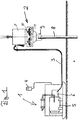
- the Fig. 1 shows the basic structure of a vibrating ram assembly, which has a hydraulic unit 1 and a vibrator 2 separated from each other, which are connected by hydraulic hoses in a hydraulic circuit and are spatially separated from each other.
- the hydraulic unit 1 has a control S, wherein the operation of the controller S can be done by means of a remote control 4 communicating by cable or wirelessly with the controller S.
- the functions for controlling the vibration ramming operation can be set by an operator.
- the hydraulic unit comprises a combustion engine 5 operated by diesel fuel as well as a hydraulic pump 6 driven by the combustion engine 5.
- the vibrator 2 is supported in the exemplary embodiment shown by a vibration isolator 7 which is suspended from a crane. On the underside of the vibrator 2, a ramming material 8 to be inserted is clamped in a hydraulic tensioning device in the form of a hydraulic collet chuck.
- the vibrator 2 on two hydraulic motors 10, with each of which two oppositely rotating imbalances 11 are driven. Due to the eccentrically mounted imbalances 11 of the vibrator 2 is vibrated in the vertical vibration vibration in the vibrating operation, which cancel the moments in the horizontal direction by an opposite movement of the imbalance 11. The drive of the imbalances 11 via not shown gears.
- the hydraulic hoses 3 are shown only schematically.
- the tensioning device 9 is supplied separately from the vibrator 2 by the hydraulic unit 1 with hydraulic oil. While a continuous flow of fluid is necessary to operate the vibrator 2, it is sufficient for the chuck 9 to build and maintain a static fluid pressure.
- At least one operating state value is interrogated by the controller S during a break in operation when the vibrator 2 is deactivated, and the internal combustion engine 5 is automatically stopped when the operating state value corresponds to a preset value.
- the controller S is further set up so that the internal combustion engine 5 starts automatically in a user signal to continue the vibration ramming operation.
- the Fig. 2 shows in a highly schematic representation of the controller S, which controls the vibrator 2, the internal combustion engine 5 and the tensioning device 9.
- the vibrator 2 and the tensioning device 9 can be controlled by providing a fluid flow or a fluid pressure with valves which can be operated by the control S.
- the query of operating state values is in the Fig. 2 indicated by dashed lines, wherein at the various devices in which the operating state value is queried, corresponding sensors may be provided.
- a check can be made as to whether the tensioning device 9 is closed. With an open clamping device 9, no vibration ramming operation is possible, so that then the internal combustion engine 5 can be stopped, for example by interrupting the fuel supply.
- an additional sensor 12 is indicated, which may be, for example, a temperature sensor in the hydraulic circuit, which determines the hydraulic oil temperature.
- a stop of the internal combustion engine 5 can also take place in a closed clamping device 9, when the vibrator 2 is not active. It is then not only the state "OPEN” and "CLOSED" of the clamping device 9, but a clamping pressure queried as operating state value. When the static clamping pressure is sufficient to keep the tensioning device 9 closed, the engine 5 can be stopped. It is also within the scope of the invention that the clamping pressure is then continuously monitored, wherein the internal combustion engine 5 is started automatically by the controller S when the clamping pressure differs from a predetermined critical value.
- the controller S can switch to a safety mode, in which case no renewed shutdown of the internal combustion engine 5 takes place. Additionally or alternatively, a user can also output a fault or error signal. If the determined Operating state value indicates a massive malfunction, the entire vibration ram assembly can be switched off.
- the condition of the vibrator can be deduced from whether it is supplied with a fluid flow.
- operating state values for example the rotational speed of the vibrator, can in principle also be interrogated on the vibrator.
Landscapes
- Engineering & Computer Science (AREA)
- General Engineering & Computer Science (AREA)
- Mechanical Engineering (AREA)
- Physics & Mathematics (AREA)
- Fluid Mechanics (AREA)
- Chemical & Material Sciences (AREA)
- Combustion & Propulsion (AREA)
- General Life Sciences & Earth Sciences (AREA)
- Life Sciences & Earth Sciences (AREA)
- Mining & Mineral Resources (AREA)
- Paleontology (AREA)
- Civil Engineering (AREA)
- Structural Engineering (AREA)
- Placing Or Removing Of Piles Or Sheet Piles, Or Accessories Thereof (AREA)
- Fluid-Pressure Circuits (AREA)
- Lubrication Of Internal Combustion Engines (AREA)
Description
- Die Erfindung betrifft ein Verfahren zum Betrieb einer Vibrationsrammanordnung umfassend ein Hydraulikaggregat mit einem Verbrennungsmotor, insbesondere einem Dieselmotor, und einer von dem Verbrennungsmotor angetriebenen Hydraulikpumpe, einen mit dem Hydraulikaggregat in einem Hydraulikkreislauf verbundenen Vibrator, der drehbar gelagerte Unwuchten und zumindest einen Hydraulikmotor als Antrieb der Unwuchten aufweist, eine an dem Vibrator angeschlossene hydraulische Spannvorrichtung für ein Rammgut und eine Steuerung mit der eine Fluidströmung durch den zumindest einen Hydraulikmotor zum Ein- und Ausschalten des Vibrator aktivierbar und deaktivierbar ist und mit der die hydraulische Spannvorrichtung geschlossen und geöffnet werden kann.
- Während des Vibrationsrammbetriebes ist die Spannvorrichtung geschlossen und der Vibrator vibriert durch eine Drehung der Unwuchten aufgrund eines Fluidstroms von Hydrauliköl durch den Hydraulikkreislauf. Eine Vibrationsrammanordnung, von der die Erfindung ausgeht, ist beispielsweise aus dem Prospekt "Müller-Vibratoren, Die perfekte Lösung zum Rammen und Ziehen", ThyssenKrupp GfT Bautechnik GmbH 5/2011 bekannt.
- Ein weiteres Beispiel einer Vibrationsrammanordnung, deren Unwuchten mittels eines hydraulischen Fluidstroms angetrieben werden, ist der
EP 2 014 835 A1 zu entnehmen. - Die Vibrationsrammung beruht auf dem Prinzip, den Boden in einen quasi flüssigen Zustand zu versetzen. Dies wird durch das Vibrieren des Rammgutes beim Auftreffen auf den Boden erreicht. Die Mantelreibung des einzutreibenden Materials wird durch das Schwingen deutlich herabgesetzt und hierdurch wird ein zügiger Eindringfortschritt ermöglicht. Die Schwingungsfrequenz kann beispielsweise zwischen 10 Hz und 60 Hz, insbesondere zwischen 30 Hz und 50 Hz betragen. Typische Rammgüter sind neben Spundwandprofilen Pfähle, Bohlen und Rohre für Gründungsstrukturen von Bauwerken und ortsfesten technischen Anlagen.
- In der Praxis ergeben sich bei dem Betrieb der Vibrationsrammanordnung häufig Betriebspausen, in denen der Vibrator deaktiviert ist, beispielsweise, wenn ein Rammgut aufgenommen und positioniert wird, wenn der Vibrator auf dem Rammgut ausgerichtet oder auch neu ausgerichtet werden muss, oder wenn der an einem Trägergerät, beispielsweise an einem Kran, angeordnete Vibrator mit oder ohne einem von der Spannvorrichtung aufgenommenen Rammgut zu einer anderen Position verfahren wird, wobei gegebenenfalls auch das Hydraulikaggregat verstellt werden muss.
- In solchen Betriebspausen kann der Verbrennungsmotor von einem Bediener angehalten, das heißt ausgeschaltet werden. In der Regel läuft der Verbrennungsmotor in Betriebspausen aber im Standgas weiter. Ein Anhalten des Verbrennungsmotors in Betriebspausen wird von einem Bediener aus mehren Gründen häufig auch überhaupt nicht in Betracht gezogen, weil dem Bediener aufgrund der räumlichen Trennung von Vibrator und Hydraulikaggregat sowie der auf einer Baustelle vorhandenen Umgebungsgeräusche nicht bewusst ist, dass der Verbrennungsmotor weiterläuft. Zusätzlich ist der Bediener in Betriebspausen oft mit anderen Aufgaben als der Bedienung der Vibrationsrammanordnung beschäftigt.
- Vor diesem Hintergrund liegt der Erfindung die Aufgabe zugrunde, ein Verfahren zum Betrieb einer Vibrationsrammanordnung anzugeben, welches ohne Einbußen an Komfort und Betriebssicherheit eine Kostenreduzierung ermöglicht. Des Weiteren soll eine Vibrationsrammanordnung angegeben werden, welche die Durchführung des Verfahren ermöglicht.
- Gegenstand der Erfindung und Lösung der Aufgabe sind ein Verfahren gemäß Patentanspruch 1 und eine Vibrationsrammanordnung gemäß Patentanspruch 8.
- Ausgehend von einem Verfahren mit den eingangs beschriebenen Merkmalen ist erfindungsgemäß vorgesehen, dass in einer Betriebspause bei einem deaktivierten Vibrator die Steuerung zumindest einen Betriebszustandswert abfragt und den Verbrennungsmotor selbsttätig anhält, wenn der Betriebszustandswert einem Vorgabewert entspricht und dass die Steuerung bei einem Benutzersignal zum Fortsetzen des Vibrationsrammbetriebes den Verbrennungsmotor selbsttätig startet.
- Erfindungsgemäß erfolgt das Anhalten des Verbrennungsmotors nicht nur unter Berücksichtigung des Aktivierungszustandes des Vibrators, sondern zusätzlich unter Berücksichtigung eines für die Vibrationsrammanordnung spezifischen Betriebszustandswertes, wobei gerade durch diese zusätzliche Abfrage ein hohes Maß an Komfort und Betriebssicherheit gewährleistet werden kann.
- Durch das Anhalten des Verbrennungsmotors in Betriebspausen kann eine erhebliche Menge an Kraftstoff, also üblicherweise Diesel, eingespart werden. Der Erfindung liegt dabei die Erkenntnis zugrunde, dass der Verbrennungsmotor oft länger ohne Last im Standgas als im eigentlichen Vibrationsrammbetrieb unter Last läuft. Abhängig von den jeweiligen Anforderungen an das Vibrationsrammen kann der Anteil der Zeit, in der der Verbrennungsmotor unter Last läuft beispielsweise nur 10% bis 20% des gesamten Betriebszeit des Hydraulikaggregates betragen.
- Die Einsparung von Kraftstoff führt zu geringeren Kosten und geringeren Abgasmengen. Des Weiteren werden auch die Geräuschemissionen insgesamt deutlich reduziert, wobei sich auch ein geringerer Verschleiß der Komponenten der Vibrationsrammanordnung ergibt. Besonders deutlich werden die Betriebsstunden des Verbrennungsmotors reduziert, welche häufig die Grundlage für die Festlegung von Wartungsintervallen und die Berechnung des Restwertes des Verbrennungsmotors bilden.
- Gemäß einer ersten Variante des erfindungsgemäßen Verfahren wird als Betriebszustandswert der Öffnungszustand der Spannvorrichtung abgefragt, wobei der Verbrennungsmotor nicht angehalten wird, wenn die Spannvorrichtung geschlossen ist. Wenn dagegen die Spannvorrichtung geöffnet ist, ist kein Eintreiben des Rammgutes möglich, so dass dann der Verbrennungsmotor angehalten werden kann, wenn keine weiteren Randbedingungen vorliegen, die einem Anhalten des Verbrennungsmotors entgegenstehen. Insbesondere können im Rahmen der Erfindung auch mehrere unterschiedliche Betriebszustandswerte abgefragt und ausgewertet werden, um zu bestimmen, ob ein Anhalten des Verbrennungsmotors vorteilhaft ist.
- Die Schaltung ist in der Regel so eingerichtet, dass die Spannvorrichtung nur geöffnet werden kann, wenn der Vibrator deaktiviert ist. Eine solche Steuerung ist leicht möglich, weil die Spannvorrichtung und der Vibrator parallel von dem Hydraulikaggregat über separate Kreisläufe bzw. Anschlüsse mit Hydrauliköl beaufschlagt werden können.
- Gemäß einer zweiten Variante des erfindungsgemäßen Verfahrens kann ein Anhalten des Verbrennungsmotors auch bei einer geschlossenen Spannvorrichtung erfolgen, solange der Vibrator deaktiviert und sichergestellt ist, dass die Spannvorrichtung geschlossen bleibt. Während der Antrieb des Vibrators einen kontinuierlichen Volumenstrom durch den Hydraulikmotor erfordert, wird bei der Spannvorrichtung vorzugsweise ein statischer Spanndruck aufgebaut und gehalten, so dass es dann nicht notwendig ist, für ein Geschlossenhalten der Spannvorrichtung Hydrauliköl mit dem Hydraulikaggregat nachzufördern.
- Der deaktivierte Zustand des Vibrators kann sich aus einer entsprechenden von einem Benutzer gewählten Einstellung an der Steuerung ergeben. Zusätzlich kann der Zustand des Vibrators auch mit einem Drehzahl- bzw. Frequenzsensor überwacht werden, wobei dann das Signal dieses Sensors im Rahmen der Erfindung als ein Betriebszustandswert berücksichtigt wird.
- Gemäß der zweiten Variante des Verfahrens ist bevorzugt vorgesehen, dass als Betriebszustandswert zumindest ein Spanndruck der Spannvorrichtung abgefragt wird, wobei der Verbrennungsmotor angehalten wird, wenn bei einer geschlossenen Spannvorrichtung der Spanndruck größer als ein Mindestdruck ist. Davon ausgehend kann des Weiteren der Spanndruck fortlaufend abgefragt werden, wobei der Verbrennungsmotor selbsttätig startet, wenn der Spanndruck kleiner als der Mindestdruck ist. Grundsätzlich kann für das Anhalten des Verbrennungsmotors ein größerer Grenzwert für den Spanndruck als für das selbsttätige Starten vorgesehen sein, um ein zu häufiges Anhalten und Starten des Verbrennungsmotors zu vermeiden.
- Bei einer Leckage an der Spannvorrichtung sowie in den Zuleitungen zu der Spannvorrichtung, bei einer Fehlfunktion eines Ventils oder einer ähnlichen Störung kann der Spanndruck bei einem angehalten Verbrennungsmotor nicht über einen längeren Zeitraum aufrechterhalten werden. Gemäß einer bevorzugten Weiterbildung der zweiten Variante des Verfahrens ist deshalb vorgesehen, dass die Steuerung in einem Sicherheitsmodus wechselt, wenn nach einem Anhalten des Verbrennungsmotors ein erneutes Starten aufgrund eines Abfalls des Spanndruckes innerhalb eines vorgegebenen Zeitintervalls erfolgt, wobei in dem Sicherheitsmodus keine erneute Abschaltung des Verbrennungsmotors erfolgt. Der Verbrennungsmotor läuft dann zumindest unabhängig von dem Aktivierungszustand des Vibrators durch, wobei aber weiterhin bei einer geöffneten Spannvorrichtung ein Anhalten des Verbrennungsmotors gemäß der ersten Variante des Verfahrens erfolgen kann.
- Durch die Überwachung des Spanndruckes kann ein besonders hohes Maß an Betriebssicherheit erreicht werden. Dabei ist es auch zweckmäßig, einem Benutzer durch eine geeignete Anzeigeeinrichtung eine Fehlermeldung bzw. eine Fehlfunktion anzuzeigen, damit dieser eine Überprüfung der Spannvorrichtung und des zugeordneten Hydraulikkreislaufes vornehmen kann. Insbesondere bei einer Leckage besteht die Gefahr einer Verschmutzung der Umgebung, welche durch die Anzeige der Fehlfunktion verhindert werden kann. Wenn die Zeit zwischen Anhalten und Starten des Verbrennungsmotors besonders kurz ist, kann dies ein Indiz für eine massive Störung sein, so dass dann die Steuerung optional auch so eingerichtet sein kann, dass die Vibrationsrammanordnung komplett abgeschaltet wird, bis eine Störung behoben oder zumindest die Steuerung zurückgesetzt ist.
- Grundsätzlich kann nach dem Vergleich des zumindest einen Betriebszustandswertes mit dem zugeordneten Vorgabewert ein Anhalten des Verbrennungsmotor erst mit einer Zeitverzögerung erfolgen, damit der Verbrennungsmotor in lediglich kurzen Betriebspausen nicht angehalten wird.
- Wenn der Verbrennungsmotor angehalten ist, wird dieser selbsttätig wieder gestartet, wenn an der Steuerung ein Benutzersignal zum Fortsetzen des Vibrationsrammbetriebs anliegt. Bei der oben beschriebenen ersten Variante des Verfahrens wird der Verbrennungsmotor zweckmäßigerweise dann gestartet, wenn ein Benutzer an der Steuerung eine Eingabe "Spannvorrichtung schließen" vornimmt. Gemäß der zweiten Variante wird der Verbrennungsmotor zweckmäßigerweise dann gestartet, wenn ein Benutzer an der Steuerung eine Eingabe "Vibrator EIN" vornimmt. Zumindest wenn der Verbrennungsmotor und das Hydrauliköl eine geeignete Betriebstemperatur aufweisen, kann der Verbrennungsmotor in der Regel unmittelbar gestartet werden, so dass ein Benutzer in der Regel überhaupt keinen Unterschied und keine Beeinträchtigung gegenüber dem aus dem Stand der Technik bekannten Verfahren wahrnimmt, bei dem der Verbrennungsmotor ohne Last im Leerlauf weiterläuft.
- Wenn das Hydrauliköl bei einer niedrigen Umgebungstemperatur und nach einer kurzen Betriebsdauer noch kalt ist, weist diese eine hohe Viskosität auf, wodurch sich bei dem Betrieb der Vibrationsrammanordnung erhöhte Reibungs- und Strömungsverluste ergeben, wobei sich auch ein erhöhter Widerstand bei einem Starten des Verbrennungsmotors ergibt. Unter diesen Umständen kann es von Vorteil sein, wenn in Betriebspausen kein Anhalten des Verbrennungsmotors erfolgt. Es kann deshalb vorgesehen sein, dass als ein zusätzlicher Betriebszustandswert eine Hydrauliköltemperatur abgefragt wird, wobei der Verbrennungsmotor nicht angehalten wird, wenn die Hydrauliköltemperatur unterhalb einer zugeordneten Mindesttemperatur liegt.
- Zusätzlich oder alternativ kann zum Schutz des Verbrennungsmotors auch eine Motoröltemperatur des Verbrennungsmotors als zusätzlicher Betriebszustandswert abgefragt werden, wobei der Verbrennungsmotor nicht angehalten wird, wenn die Motoröltemperatur unterhalb einer zugeordneten Mindesttemperatur liegt.
- Bei einem angehalten Verbrennungsmotor kann auch die Hydrauliköltemperatur und/oder die Motoröltemperatur laufend überwacht werden, wobei dann bei dem Unterschreiten einer vorgegebenen Untergrenze ein Starten des Verbrennungsmotors erfolgt, um eine übermäßige Abkühlung zu vermeiden.
- Gegenstand der Erfindung ist auch eine Vibrationsrammanordnung zur Durchführung des erfindungsgemäßen Verfahrens. Die Vibrationsrammanordnung umfasst ein Hydraulikaggregat mit einem Verbrennungsmotor und einer von dem Verbrennungsmotor angetriebenen Hydraulikpumpe, einen mit dem Hydraulikaggregat in einem Hydraulikkreislauf verbundenen Vibrator, der drehbar gelagerte Unwuchten und zumindest einen Hydraulikmotor als Antrieb der Unwuchten aufweist, eine an dem Vibrator angeschlossene hydraulische Spannvorrichtung für ein Rammgut, und eine Steuerung mit der eine Fluidströmung durch den zumindest einen Hydraulikmotor zum Ein- und Ausschalten des Vibrators aktivierbar und deaktivierbar ist und mit der die hydraulische Spannvorrichtung geschlossen und geöffnet werden kann.
- Die Vibrationsrammanordnung ist dadurch gekennzeichnet, dass die Steuerung dazu eingerichtet ist, in einer Betriebspause bei einem deaktivierten Vibrator zumindest einen Betriebszustandswert abzufragen und den Verbrennungsmotor selbsttätig anzuhalten, wenn der Betriebszustandswert einem Vorgabewert entspricht und dass die Steuerung dazu eingerichtet ist, bei einem Benutzersignal zum Fortsetzen des Vibrationsrammbetriebes den Verbrennungsmotor selbsttätig startet.
- Die Erfindung wird im Folgenden anhand einer lediglich ein Ausführungsbeispiel darstellenden Zeichnung erläutert. Es zeigen:
- Fig. 1
- eine Vibrationsrammanordnung;
- Fig. 2
- eine schematisierte Schaltung der Vibrationsrammanordnung gemäß
Fig. 1 . - Die
Fig. 1 zeigt den grundsätzlichen Aufbau einer Vibrationsrammanordnung, welche getrennt voneinander ein Hydraulikaggregat 1 und einen Vibrator 2 aufweist, die durch Hydraulikschläuche in einem Hydraulikkreislauf verbunden und so räumlich voneinander getrennt sind. Das Hydraulikaggregat 1 weist eine Steuerung S auf, wobei die Bedienung der Steuerung S mittels einer per Kabel oder kabellos mit der Steuerung S kommunizierenden Fernbedienung 4 erfolgen kann. An der Fernbedienung 4 können die Funktionen für die Steuerung des Vibrationsrammbetriebes von einem Bediener eingestellt werden. - Das Hydraulikaggregat umfasst einen mit Diesel betriebenen Verbrennungsmotor 5 sowie eine von dem Verbrennungsmotor 5 angetriebenen Hydraulikpumpe 6. Der Vibrator 2 ist in dem dargestellten Ausführungsbeispiel über einen Schwingungsisolator 7 abgestützt, der an einem Kran aufgehängt ist. An der Unterseite des Vibrators 2 ist ein einzutragendes Rammgut 8 in einer hydraulischen Spannvorrichtung in Form einer hydraulischen Spannzange eingespannt.
- In dem dargestellten Ausführungsbeispiel weist der Vibrator 2 zwei Hydraulikmotoren 10 auf, mit denen jeweils zwei entgegengesetzt rotierende Unwuchten 11 antreibbar sind. Durch die exzentrisch gelagerten Unwuchten 11 wird der Vibrator 2 bei dem Vibrationsrammbetrieb in vertikaler Richtung in Schwingungen versetzt, wobei sich durch eine gegenläufige Bewegung der Unwuchten 11 die Momente in horizontaler Richtung aufheben. Der Antrieb der Unwuchten 11 erfolgt über nicht dargestellte Zahnräder.
- Damit die Hydraulikmotoren 10 die Unwuchten 11 kontinuierlich antreiben, wird mit der von dem Verbrennungsmotor 5 angetriebenen Hydraulikpumpe 6 ein kontinuierlicher Fluidstrom von Hydrauliköl durch den Hydraulikkreislauf geführt.
- In der
Fig. 1 sind die Hydraulikschläuche 3 lediglich schematisch dargestellt. Üblicherweise wird die Spannvorrichtung 9 getrennt von dem Vibrator 2 von dem Hydraulikaggregat 1 mit Hydrauliköl versorgt. Während für den Betrieb des Vibrators 2 ein kontinuierlicher Fluidstrom notwendig ist, ist es für die Spannvorrichtung 9 ausreichend, wenn ein statischer Fluiddruck aufgebaut und gehalten wird. - Erfindungsgemäß ist vorgesehen, dass in einer Betriebspause bei einem deaktivierten Vibrator 2 von der Steuerung S zumindest ein Betriebszustandswert abgefragt und der Verbrennungsmotor 5 selbsttätig angehalten wird, wenn der Betriebszustandswert einem Vorgabewert entspricht. Die Steuerung S ist des Weiteren so eingerichtet, dass bei einem Benutzersignal zum Fortsetzen des Vibrationsrammbetriebes der Verbrennungsmotor 5 selbsttätig startet. Die
Fig. 2 zeigt in einer stark schematisierten Darstellung die Steuerung S, welche den Vibrator 2, den Verbrennungsmotor 5 und die Spannvorrichtung 9 steuert. Der Vibrator 2 sowie die Spannvorrichtung 9 können dadurch gesteuert werden, dass mit von der Steuerung S bedienbaren Ventilen ein Fluidstrom bzw. ein Fluiddruck bereitgestellt werden. - Die Abfrage von Betriebszustandswerten ist in der
Fig. 2 durch gestrichelte Linien angedeutet, wobei an den verschiedenen Einrichtungen, an denen der Betriebszustandswert abgefragt wird, entsprechende Sensoren vorgesehen sein können. - Im einfachsten Fall kann eine Überprüfung erfolgen, ob die Spannvorrichtung 9 geschlossen ist. Bei einer geöffneten Spannvorrichtung 9 ist kein Vibrationsrammbetrieb möglich, so dass dann der Verbrennungsmotor 5, beispielsweise durch eine Unterbrechung der Kraftstoffzufuhr, angehalten werden kann.
- Auch wenn die Spannvorrichtung 9 geöffnet ist, kann unter bestimmten Umständen ein Anhalten des Verbrennungsmotors 5 nachteilig sein, insbesondere wenn eine Motoröltemperatur des Verbrennungsmotors 5 oder eine Hydrauliköltemperatur des Hydrauliköls in dem Hydraulikkreislauf zu niedrig sind. Entsprechend können auch an dem Verbrennungsmotor 5 Betriebszustandswerte abgefragt werden, anhand welcher die Steuerung S entscheidet, ob ein Anhalten des Verbrennungsmotors 5 zweckmäßig ist. In der
Fig. 2 ist des Weiteren ein zusätzlicher Sensor 12 angedeutet, wobei es sich beispielsweise um einen Temperaturfühler in dem Hydraulikkreislauf handeln kann, der die Hydrauliköltemperatur bestimmt. - Gemäß einer Variante des erfindungsgemäßen Verfahrens, kann ein Anhalten des Verbrennungsmotors 5 auch bei einer geschlossenen Spannvorrichtung 9 erfolgen, wenn der Vibrator 2 nicht aktiv ist. Es wird dann nicht nur der Zustand "AUF" und "ZU" der Spannvorrichtung 9, sondern ein Spanndruck als Betriebszustandswert abgefragt. Wenn der statische Spanndruck ausreichend ist, um die Spannvorrichtung 9 geschlossen zu halten, kann der Verbrennungsmotor 5 angehalten werden. Im Rahmen der Erfindung liegt es auch, dass dann der Spanndruck laufend überwacht wird, wobei der Verbrennungsmotor 5 von der Steuerung S selbsttätig gestartet wird, wenn der Spanndruck einen vorgegebenen kritischen Wert unterscheidet.
- Falls dies bereits nach einer kurzen Zeit erfolgt, kann dieses Verhalten ein Hinweis auf eine Fehlfunktion sein, so dass dann verschiedene Sicherheitsmaßnahmen ergriffen werden können. Zunächst kann die Steuerung S in einen Sicherheitsmodus wechseln, wobei dann keine erneute Abschaltung des Verbrennungsmotors 5 erfolgt. Zusätzlich oder alternativ kann einem Benutzer auch ein Stör- oder Fehlersignal ausgegeben werden. Wenn der ermittelte Betriebszustandswert auf eine massive Fehlfunktion hinweist, kann auch die gesamte Vibrationsrammanordnung abgeschaltet werden.
- Der Zustand des Vibrators kann daraus abgeleitet werden, ob dieser mit einem Fluidstrom versorgt wird. In der
Fig. 2 ist auch angedeutet, dass aber grundsätzlich auch an dem Vibrator Betriebszustandswerte, beispielsweise die Drehzahl des Vibrators abgefragt werden können.
Claims (8)
- Verfahren zum Betrieb einer Vibrationsrammanordnung umfassendein Hydraulikaggregat (1) mit einem Verbrennungsmotor (5) und einer von dem Verbrennungsmotor (5) angetriebenen Hydraulikpumpe (6),einen mit dem Hydraulikaggregat (1) in einem Hydraulikkreislauf verbundenen Vibrator (2), der drehbar gelagerte Unwuchten (11) und zumindest einen Hydraulikmotor (10) als Antrieb der Unwuchten (11) aufweist,eine an dem Vibrator (2) angeschlossene hydraulische Spannvorrichtung (9) für ein Rammgut (8) undeine Steuerung (S), mit der eine Fluidströmung durch den zumindest einen Hydraulikmotor (10) zum Ein- und Ausschalten des Vibrators (2) aktivierbar und deaktivierbar ist und mit der die hydraulische Spannvorrichtung (9) geschlossen und geöffnet werden kann,wobei während des Vibrationsrammbetriebes die Spannvorrichtung (9) geschlossen ist und der Vibrator (2) durch eine Drehung der Unwuchten (11) aufgrund eines Fluidstroms von Hydrauliköl durch den Hydraulikkreislauf vibriert, dadurch gekennzeichnet, dass in einer Betriebspause bei einem deaktivierten Vibrator (2) die Steuerung (S) zumindest einen Betriebszustandswert abfragt und den Verbrennungsmotor (5) selbsttätig ausschaltet, wenn der Betriebszustandswert einem Vorgabewert entspricht und dass die Steuerung (S) bei einem Benutzersignal zum Fortsetzen des Vibrationsrammbetriebes den Verbrennungsmotor (5) selbsttätig startet.
- Verfahren nach Anspruch 1, dadurch gekennzeichnet, dass als Betriebszustandswert der Öffnungszustand der Spannvorrichtung (9) abgefragt wird, wobei der Verbrennungsmotor (5) nicht ausgeschaltet wird, wenn die Spannvorrichtung (9) geschlossen ist.
- Verfahren nach Anspruch 1, dadurch gekennzeichnet, dass als Betriebszustandswert ein Spanndruck der Spannvorrichtung (9) abgefragt wird, wobei der Verbrennungsmotor (5) ausgeschaltet wird, wenn bei einer geschlossenen Spannvorrichtung (9) der Spanndruck größer als ein Mindestdruck ist, wobei der Spanndruck fortlaufend abgefragt wird und wobei der Verbrennungsmotor (5) selbsttätig startet, wenn der Spanndruck kleiner als der Mindestdruck ist.
- Verfahren nach Anspruch 3, dadurch gekennzeichnet, dass die Steuerung (S) in einem Sicherheitsmodus wechselt, wenn nach einem Ausschalten des Verbrennungsmotors (5) ein erneutes Starten aufgrund eines Abfalls des Spanndruckes innerhalb eines vorgegebenen Zeitintervalls erfolgt, wobei in dem Sicherheitsmodus kein erneutes Ausschalten des Verbrennungsmotors (5) erfolgt.
- Verfahren nach einem der Ansprüche 1 bis 4, dadurch gekennzeichnet, dass nach dem Vergleich des zumindest einen Betriebszustandswertes mit dem zugeordneten Vorgabewert ein Ausschalten des Verbrennungsmotors (5) erst mit einer Zeitverzögerung erfolgt.
- Verfahren nach einem der Ansprüche 1 bis 5, dadurch gekennzeichnet, dass als ein zusätzlicher Betriebszustandswert eine Hydrauliköltemperatur abgefragt wird, wobei der Verbrennungsmotor (5) nicht ausgeschaltet wird, wenn die Hydrauliköltemperatur unterhalb einer zugeordneten Mindesttemperatur liegt.
- Verfahren nach einem der Ansprüche 1 bis 6, dadurch gekennzeichnet, dass als ein zusätzlicher Betriebszustandswert eine Motoröltemperatur des Verbrennungsmotors (5) abgefragt wird, wobei der Verbrennungsmotor (5) nicht ausgeschaltet wird, wenn die Motoröltemperatur unterhalb einer zugeordneten Mindesttemperatur liegt.
- Vibrationsrammanordnung umfassendein Hydraulikaggregat (1) mit einem Verbrennungsmotor (5) und einer von dem Verbrennungsmotor (5) angetriebenen Hydraulikpumpe,einen mit dem Hydraulikaggregat (1) in einem Hydraulikkreislauf verbundenen Vibrator (2), der drehbar gelagerte Unwuchten (11) und zumindest einen Hydraulikmotor (10) als Antrieb der Unwuchten (11) aufweist,eine an dem Vibrator (2) angeschlossene hydraulische Spannvorrichtung (9) für ein Rammgut (8) undeine Steuerung (S), mit der eine Fluidströmung durch den zumindest einen Hydraulikmotor (10) zum Ein- und Ausschalten des Vibrators (2) aktivierbar und deaktivierbar ist und mit der die hydraulische Spannvorrichtung (9) geschlossen und geöffnet werden kann,dadurch gekennzeichnet, dass die Steuerung (S) dazu eingerichtet ist, in einer Betriebspause bei einem deaktivierten Vibrator (2) zumindest einen Betriebszustandswert an einem Sensor abzufragen und den Verbrennungsmotor (5) selbsttätig auszuschalten, wenn der Betriebszustandswert einem Vorgabewert entspricht und dass die Steuerung (S) dazu eingerichtet ist, bei einem Benutzersignal zum Fortsetzen des Vibrationsrammbetriebes den Verbrennungsmotor (5) selbsttätig startet.
Applications Claiming Priority (2)
| Application Number | Priority Date | Filing Date | Title |
|---|---|---|---|
| DE102013103715.1A DE102013103715B4 (de) | 2013-04-12 | 2013-04-12 | Verfahren zum Betrieb einer Vibrationsrammanordnung |
| PCT/EP2014/000854 WO2014166605A1 (de) | 2013-04-12 | 2014-03-31 | Verfahren zum betrieb einer vibrationsrammanordnung |
Publications (2)
| Publication Number | Publication Date |
|---|---|
| EP2984240A1 EP2984240A1 (de) | 2016-02-17 |
| EP2984240B1 true EP2984240B1 (de) | 2017-05-03 |
Family
ID=50489052
Family Applications (1)
| Application Number | Title | Priority Date | Filing Date |
|---|---|---|---|
| EP14717670.5A Active EP2984240B1 (de) | 2013-04-12 | 2014-03-31 | Verfahren zum betrieb einer vibrationsrammanordnung |
Country Status (4)
| Country | Link |
|---|---|
| US (1) | US9835178B2 (de) |
| EP (1) | EP2984240B1 (de) |
| DE (1) | DE102013103715B4 (de) |
| WO (1) | WO2014166605A1 (de) |
Families Citing this family (2)
| Publication number | Priority date | Publication date | Assignee | Title |
|---|---|---|---|---|
| EP3696327B1 (de) | 2019-02-15 | 2021-02-24 | ABI Anlagentechnik-Baumaschinen-Industriebedarf Maschinenfabrik und Vertriebsgesellschaft mbH | Tiefbaugerät |
| CN113464507B (zh) * | 2020-03-31 | 2025-04-15 | 徐州徐工挖掘机械有限公司 | 打桩机液压控制系统 |
Family Cites Families (9)
| Publication number | Priority date | Publication date | Assignee | Title |
|---|---|---|---|---|
| DE2236134A1 (de) | 1972-07-22 | 1974-02-07 | Rexroth Gmbh G L | Aus einer verstellbaren hydropumpe und einem hydromotor gebildetes getriebe |
| DE2700803C2 (de) | 1977-01-11 | 1982-10-28 | Sauer Getriebe KG, 2350 Neumünster | Regelungssystem für eine Antriebseinrichtung |
| DE3806194A1 (de) | 1988-01-14 | 1989-08-03 | Hydromatik Gmbh | Automotive antriebseinrichtung fuer maschinen und fahrzeuge |
| JP4010255B2 (ja) * | 2003-02-07 | 2007-11-21 | コベルコ建機株式会社 | 建設機械の制御装置 |
| DE102005021687A1 (de) * | 2005-05-11 | 2006-11-16 | Thyssenkrupp Gft Tiefbautechnik Gmbh | Hydraulische Steuereinheit für ein Ramm-oder Ziehgerät |
| FR2918473B1 (fr) * | 2007-07-03 | 2009-10-30 | Ptc Sa | Systeme d'asservissement d'un groupe hydraulique alimentant en fluide hydraulique un vibrateur. |
| DE202007014676U1 (de) | 2007-10-19 | 2009-02-26 | Liebherr-Machines Bulle S.A. | Hydraulisches Antriebssystem |
| EP2557233B2 (de) | 2011-08-12 | 2022-06-01 | ABI Anlagentechnik-Baumaschinen-Industriebedarf Maschinenfabrik und Vertriebsgesellschaft mbH | Arbeitsgerät mit hydraulischem Antrieb für Tiefbauarbeiten |
| US8727233B2 (en) * | 2011-10-17 | 2014-05-20 | Champion Power Equipment, Inc. | Pressure spray washer and control |
-
2013
- 2013-04-12 DE DE102013103715.1A patent/DE102013103715B4/de active Active
-
2014
- 2014-03-31 EP EP14717670.5A patent/EP2984240B1/de active Active
- 2014-03-31 WO PCT/EP2014/000854 patent/WO2014166605A1/de not_active Ceased
- 2014-03-31 US US14/784,016 patent/US9835178B2/en active Active
Also Published As
| Publication number | Publication date |
|---|---|
| EP2984240A1 (de) | 2016-02-17 |
| WO2014166605A1 (de) | 2014-10-16 |
| US9835178B2 (en) | 2017-12-05 |
| US20160069357A1 (en) | 2016-03-10 |
| DE102013103715A1 (de) | 2014-10-16 |
| DE102013103715B4 (de) | 2016-12-08 |
Similar Documents
| Publication | Publication Date | Title |
|---|---|---|
| EP2984241B1 (de) | Vibrationsrammanordnung sowie verfahren zum betrieb der vibrationsrammanordnung | |
| AT511612B1 (de) | Verfahren zum starten einer brennkraftmaschine | |
| DE112007001729B4 (de) | Verfahren zum Betreiben einer Fluidarbeitsmaschine und eine Fluidarbeitsmaschine | |
| DE102006000021A1 (de) | Kraftstoffeinspritzsystem, das einen Betrieb im Falle einer unüblichen Bedingung sicherstellt | |
| DE102007005284A1 (de) | Verfahren zum Zusammenfügen von Bauteilen durch Spannbolzen | |
| EP3242033B1 (de) | Verfahren zum betreiben eines elektronisch gesteuerten pumpenaggregates | |
| DE112007002011T5 (de) | System zur dynamischen Detektion einer Brennstoffleckage | |
| EP2918874A1 (de) | Verfahren zum Betreiben eines Hydrauliksystems eines Automatikgetriebes | |
| DE102013103715B4 (de) | Verfahren zum Betrieb einer Vibrationsrammanordnung | |
| EP3696327B1 (de) | Tiefbaugerät | |
| DE102004005851B4 (de) | Vorrichtung und Verfahren zum Überwachen einer Kraftstofffördervorrichtung | |
| EP3591180B1 (de) | Betriebsverfahren und steuereinheit für einen aktiven ölabscheider, aktiver ölabscheider und arbeitsvorrichtung | |
| EP1722036A2 (de) | Bodenverdichtungsgerät | |
| DE10031892A1 (de) | Verfahren zur Steuerung der Geschwindigkeit eines elektrohydraulischen Hubantriebs | |
| EP1595073B1 (de) | Verfahren zum betreiben eines einspritzventils einer brennkraftmaschine | |
| WO2017186712A1 (de) | Hydraulische achse für eine presse | |
| DE102008042980A1 (de) | Verfahren zur Bestimmung der Lage eines oberen Totpunkts einer Brennkraftmaschine | |
| AT515056A2 (de) | Motorsteuergerät | |
| DE102015219152B4 (de) | Schwingungsdämpfer für eine Kraftstoffhochdruckpumpe, Kraftstoffhochdruckpumpe mit Schwingungsdämpfer und Verfahren zur Steuerung eines solchen Schwingungsdämpfers | |
| EP2053249A2 (de) | Anordnung mit Vakuumpumpe und Verfahren | |
| DE10353141A1 (de) | Verfahren zum Entleeren des Kraftstoffspeichers eines Einspritzsystems einer Brennkraftmaschine | |
| DE102013103675B4 (de) | Hydraulisch angetriebene Arbeitsmaschine sowie Anordnung mit Arbeitsmaschine und Hydraulikaggregat | |
| DE159674C (de) | ||
| DE102012014252B3 (de) | Verfahren zum Betreiben einer Kraftstofftankeinrichtung sowie entsprechende Kraftstofftankeinrichtung | |
| DE102010062880A1 (de) | Verfahren zum Betreiben eines Abtriebsaggregats |
Legal Events
| Date | Code | Title | Description |
|---|---|---|---|
| PUAI | Public reference made under article 153(3) epc to a published international application that has entered the european phase |
Free format text: ORIGINAL CODE: 0009012 |
|
| 17P | Request for examination filed |
Effective date: 20151009 |
|
| AK | Designated contracting states |
Kind code of ref document: A1 Designated state(s): AL AT BE BG CH CY CZ DE DK EE ES FI FR GB GR HR HU IE IS IT LI LT LU LV MC MK MT NL NO PL PT RO RS SE SI SK SM TR |
|
| AX | Request for extension of the european patent |
Extension state: BA ME |
|
| DAX | Request for extension of the european patent (deleted) | ||
| 17Q | First examination report despatched |
Effective date: 20160729 |
|
| REG | Reference to a national code |
Ref country code: DE Ref legal event code: R079 Free format text: PREVIOUS MAIN CLASS: E02D0007100000 Ipc: E02D0007180000 |
|
| GRAP | Despatch of communication of intention to grant a patent |
Free format text: ORIGINAL CODE: EPIDOSNIGR1 |
|
| RIC1 | Information provided on ipc code assigned before grant |
Ipc: E02D 7/18 20060101AFI20161129BHEP |
|
| INTG | Intention to grant announced |
Effective date: 20161215 |
|
| RBV | Designated contracting states (corrected) |
Designated state(s): AL AT BE BG CH CY CZ DK EE ES FI FR GB GR HR HU IE IS IT LI LT LU LV MC MK MT NL NO PL PT RO RS SE SI SK SM TR |
|
| REG | Reference to a national code |
Ref country code: DE Ref legal event code: R108 |
|
| GRAS | Grant fee paid |
Free format text: ORIGINAL CODE: EPIDOSNIGR3 |
|
| GRAA | (expected) grant |
Free format text: ORIGINAL CODE: 0009210 |
|
| RAP1 | Party data changed (applicant data changed or rights of an application transferred) |
Owner name: THYSSENKRUPP INFRASTRUCTURE GMBH |
|
| AK | Designated contracting states |
Kind code of ref document: B1 Designated state(s): AL AT BE BG CH CY CZ DK EE ES FI FR GB GR HR HU IE IS IT LI LT LU LV MC MK MT NL NO PL PT RO RS SE SI SK SM TR |
|
| REG | Reference to a national code |
Ref country code: GB Ref legal event code: FG4D Free format text: NOT ENGLISH |
|
| REG | Reference to a national code |
Ref country code: AT Ref legal event code: REF Ref document number: 890144 Country of ref document: AT Kind code of ref document: T Effective date: 20170515 Ref country code: CH Ref legal event code: EP |
|
| REG | Reference to a national code |
Ref country code: IE Ref legal event code: FG4D Free format text: LANGUAGE OF EP DOCUMENT: GERMAN |
|
| REG | Reference to a national code |
Ref country code: NL Ref legal event code: FP |
|
| REG | Reference to a national code |
Ref country code: CH Ref legal event code: NV Representative=s name: FIAMMENGHI-FIAMMENGHI, CH Ref country code: CH Ref legal event code: PK Free format text: BERICHTIGUNG INHABER |
|
| REG | Reference to a national code |
Ref country code: LT Ref legal event code: MG4D |
|
| PG25 | Lapsed in a contracting state [announced via postgrant information from national office to epo] |
Ref country code: FI Free format text: LAPSE BECAUSE OF FAILURE TO SUBMIT A TRANSLATION OF THE DESCRIPTION OR TO PAY THE FEE WITHIN THE PRESCRIBED TIME-LIMIT Effective date: 20170503 Ref country code: NO Free format text: LAPSE BECAUSE OF FAILURE TO SUBMIT A TRANSLATION OF THE DESCRIPTION OR TO PAY THE FEE WITHIN THE PRESCRIBED TIME-LIMIT Effective date: 20170803 Ref country code: HR Free format text: LAPSE BECAUSE OF FAILURE TO SUBMIT A TRANSLATION OF THE DESCRIPTION OR TO PAY THE FEE WITHIN THE PRESCRIBED TIME-LIMIT Effective date: 20170503 Ref country code: GR Free format text: LAPSE BECAUSE OF FAILURE TO SUBMIT A TRANSLATION OF THE DESCRIPTION OR TO PAY THE FEE WITHIN THE PRESCRIBED TIME-LIMIT Effective date: 20170804 Ref country code: ES Free format text: LAPSE BECAUSE OF FAILURE TO SUBMIT A TRANSLATION OF THE DESCRIPTION OR TO PAY THE FEE WITHIN THE PRESCRIBED TIME-LIMIT Effective date: 20170503 Ref country code: LT Free format text: LAPSE BECAUSE OF FAILURE TO SUBMIT A TRANSLATION OF THE DESCRIPTION OR TO PAY THE FEE WITHIN THE PRESCRIBED TIME-LIMIT Effective date: 20170503 |
|
| PG25 | Lapsed in a contracting state [announced via postgrant information from national office to epo] |
Ref country code: PL Free format text: LAPSE BECAUSE OF FAILURE TO SUBMIT A TRANSLATION OF THE DESCRIPTION OR TO PAY THE FEE WITHIN THE PRESCRIBED TIME-LIMIT Effective date: 20170503 Ref country code: BG Free format text: LAPSE BECAUSE OF FAILURE TO SUBMIT A TRANSLATION OF THE DESCRIPTION OR TO PAY THE FEE WITHIN THE PRESCRIBED TIME-LIMIT Effective date: 20170803 Ref country code: SE Free format text: LAPSE BECAUSE OF FAILURE TO SUBMIT A TRANSLATION OF THE DESCRIPTION OR TO PAY THE FEE WITHIN THE PRESCRIBED TIME-LIMIT Effective date: 20170503 Ref country code: IS Free format text: LAPSE BECAUSE OF FAILURE TO SUBMIT A TRANSLATION OF THE DESCRIPTION OR TO PAY THE FEE WITHIN THE PRESCRIBED TIME-LIMIT Effective date: 20170903 Ref country code: LV Free format text: LAPSE BECAUSE OF FAILURE TO SUBMIT A TRANSLATION OF THE DESCRIPTION OR TO PAY THE FEE WITHIN THE PRESCRIBED TIME-LIMIT Effective date: 20170503 Ref country code: RS Free format text: LAPSE BECAUSE OF FAILURE TO SUBMIT A TRANSLATION OF THE DESCRIPTION OR TO PAY THE FEE WITHIN THE PRESCRIBED TIME-LIMIT Effective date: 20170503 |
|
| PG25 | Lapsed in a contracting state [announced via postgrant information from national office to epo] |
Ref country code: RO Free format text: LAPSE BECAUSE OF FAILURE TO SUBMIT A TRANSLATION OF THE DESCRIPTION OR TO PAY THE FEE WITHIN THE PRESCRIBED TIME-LIMIT Effective date: 20170503 Ref country code: DK Free format text: LAPSE BECAUSE OF FAILURE TO SUBMIT A TRANSLATION OF THE DESCRIPTION OR TO PAY THE FEE WITHIN THE PRESCRIBED TIME-LIMIT Effective date: 20170503 Ref country code: EE Free format text: LAPSE BECAUSE OF FAILURE TO SUBMIT A TRANSLATION OF THE DESCRIPTION OR TO PAY THE FEE WITHIN THE PRESCRIBED TIME-LIMIT Effective date: 20170503 Ref country code: CZ Free format text: LAPSE BECAUSE OF FAILURE TO SUBMIT A TRANSLATION OF THE DESCRIPTION OR TO PAY THE FEE WITHIN THE PRESCRIBED TIME-LIMIT Effective date: 20170503 Ref country code: SK Free format text: LAPSE BECAUSE OF FAILURE TO SUBMIT A TRANSLATION OF THE DESCRIPTION OR TO PAY THE FEE WITHIN THE PRESCRIBED TIME-LIMIT Effective date: 20170503 |
|
| PG25 | Lapsed in a contracting state [announced via postgrant information from national office to epo] |
Ref country code: SM Free format text: LAPSE BECAUSE OF FAILURE TO SUBMIT A TRANSLATION OF THE DESCRIPTION OR TO PAY THE FEE WITHIN THE PRESCRIBED TIME-LIMIT Effective date: 20170503 |
|
| PLBE | No opposition filed within time limit |
Free format text: ORIGINAL CODE: 0009261 |
|
| STAA | Information on the status of an ep patent application or granted ep patent |
Free format text: STATUS: NO OPPOSITION FILED WITHIN TIME LIMIT |
|
| REG | Reference to a national code |
Ref country code: FR Ref legal event code: PLFP Year of fee payment: 5 |
|
| 26N | No opposition filed |
Effective date: 20180206 |
|
| PG25 | Lapsed in a contracting state [announced via postgrant information from national office to epo] |
Ref country code: SI Free format text: LAPSE BECAUSE OF FAILURE TO SUBMIT A TRANSLATION OF THE DESCRIPTION OR TO PAY THE FEE WITHIN THE PRESCRIBED TIME-LIMIT Effective date: 20170503 |
|
| PG25 | Lapsed in a contracting state [announced via postgrant information from national office to epo] |
Ref country code: MT Free format text: LAPSE BECAUSE OF FAILURE TO SUBMIT A TRANSLATION OF THE DESCRIPTION OR TO PAY THE FEE WITHIN THE PRESCRIBED TIME-LIMIT Effective date: 20170503 |
|
| PG25 | Lapsed in a contracting state [announced via postgrant information from national office to epo] |
Ref country code: MC Free format text: LAPSE BECAUSE OF FAILURE TO SUBMIT A TRANSLATION OF THE DESCRIPTION OR TO PAY THE FEE WITHIN THE PRESCRIBED TIME-LIMIT Effective date: 20170503 |
|
| REG | Reference to a national code |
Ref country code: BE Ref legal event code: MM Effective date: 20180331 |
|
| REG | Reference to a national code |
Ref country code: IE Ref legal event code: MM4A |
|
| PG25 | Lapsed in a contracting state [announced via postgrant information from national office to epo] |
Ref country code: LU Free format text: LAPSE BECAUSE OF NON-PAYMENT OF DUE FEES Effective date: 20180331 |
|
| PG25 | Lapsed in a contracting state [announced via postgrant information from national office to epo] |
Ref country code: IE Free format text: LAPSE BECAUSE OF NON-PAYMENT OF DUE FEES Effective date: 20180331 |
|
| PG25 | Lapsed in a contracting state [announced via postgrant information from national office to epo] |
Ref country code: BE Free format text: LAPSE BECAUSE OF NON-PAYMENT OF DUE FEES Effective date: 20180331 |
|
| PG25 | Lapsed in a contracting state [announced via postgrant information from national office to epo] |
Ref country code: TR Free format text: LAPSE BECAUSE OF FAILURE TO SUBMIT A TRANSLATION OF THE DESCRIPTION OR TO PAY THE FEE WITHIN THE PRESCRIBED TIME-LIMIT Effective date: 20170503 |
|
| PG25 | Lapsed in a contracting state [announced via postgrant information from national office to epo] |
Ref country code: PT Free format text: LAPSE BECAUSE OF FAILURE TO SUBMIT A TRANSLATION OF THE DESCRIPTION OR TO PAY THE FEE WITHIN THE PRESCRIBED TIME-LIMIT Effective date: 20170503 |
|
| PG25 | Lapsed in a contracting state [announced via postgrant information from national office to epo] |
Ref country code: CY Free format text: LAPSE BECAUSE OF FAILURE TO SUBMIT A TRANSLATION OF THE DESCRIPTION OR TO PAY THE FEE WITHIN THE PRESCRIBED TIME-LIMIT Effective date: 20170503 Ref country code: MK Free format text: LAPSE BECAUSE OF NON-PAYMENT OF DUE FEES Effective date: 20170503 Ref country code: HU Free format text: LAPSE BECAUSE OF FAILURE TO SUBMIT A TRANSLATION OF THE DESCRIPTION OR TO PAY THE FEE WITHIN THE PRESCRIBED TIME-LIMIT; INVALID AB INITIO Effective date: 20140331 |
|
| PG25 | Lapsed in a contracting state [announced via postgrant information from national office to epo] |
Ref country code: AL Free format text: LAPSE BECAUSE OF FAILURE TO SUBMIT A TRANSLATION OF THE DESCRIPTION OR TO PAY THE FEE WITHIN THE PRESCRIBED TIME-LIMIT Effective date: 20170503 |
|
| REG | Reference to a national code |
Ref country code: GB Ref legal event code: 732E Free format text: REGISTERED BETWEEN 20220616 AND 20220622 |
|
| REG | Reference to a national code |
Ref country code: NL Ref legal event code: PD Owner name: TERRA INFRASTRUCTURE GMBH; DE Free format text: DETAILS ASSIGNMENT: CHANGE OF OWNER(S), ASSIGNMENT; FORMER OWNER NAME: THYSSENKRUPP INFRASTRUCTURE GMBH Effective date: 20220713 |
|
| REG | Reference to a national code |
Ref country code: AT Ref legal event code: PC Ref document number: 890144 Country of ref document: AT Kind code of ref document: T Owner name: TERRA INFRASTRUCTURE GMBH, DE Effective date: 20220830 |
|
| P01 | Opt-out of the competence of the unified patent court (upc) registered |
Effective date: 20230529 |
|
| PGFP | Annual fee paid to national office [announced via postgrant information from national office to epo] |
Ref country code: NL Payment date: 20240320 Year of fee payment: 11 |
|
| PGFP | Annual fee paid to national office [announced via postgrant information from national office to epo] |
Ref country code: IT Payment date: 20250331 Year of fee payment: 12 |
|
| PGFP | Annual fee paid to national office [announced via postgrant information from national office to epo] |
Ref country code: CH Payment date: 20250401 Year of fee payment: 12 |
|
| REG | Reference to a national code |
Ref country code: NL Ref legal event code: MM Effective date: 20250401 |
|
| PG25 | Lapsed in a contracting state [announced via postgrant information from national office to epo] |
Ref country code: NL Free format text: LAPSE BECAUSE OF NON-PAYMENT OF DUE FEES Effective date: 20250401 |
|
| REG | Reference to a national code |
Ref country code: CH Ref legal event code: U11 Free format text: ST27 STATUS EVENT CODE: U-0-0-U10-U11 (AS PROVIDED BY THE NATIONAL OFFICE) Effective date: 20260401 |
|
| PGFP | Annual fee paid to national office [announced via postgrant information from national office to epo] |
Ref country code: GB Payment date: 20260324 Year of fee payment: 13 |
|
| PGFP | Annual fee paid to national office [announced via postgrant information from national office to epo] |
Ref country code: AT Payment date: 20260319 Year of fee payment: 13 |
|
| PGFP | Annual fee paid to national office [announced via postgrant information from national office to epo] |
Ref country code: FR Payment date: 20260324 Year of fee payment: 13 |