EP2982899A1 - Flächige ausstellungsleuchte - Google Patents
Flächige ausstellungsleuchte Download PDFInfo
- Publication number
- EP2982899A1 EP2982899A1 EP15179811.3A EP15179811A EP2982899A1 EP 2982899 A1 EP2982899 A1 EP 2982899A1 EP 15179811 A EP15179811 A EP 15179811A EP 2982899 A1 EP2982899 A1 EP 2982899A1
- Authority
- EP
- European Patent Office
- Prior art keywords
- light
- light guide
- face
- reflector
- luminaire
- Prior art date
- Legal status (The legal status is an assumption and is not a legal conclusion. Google has not performed a legal analysis and makes no representation as to the accuracy of the status listed.)
- Granted
Links
Images

Classifications
-
- F—MECHANICAL ENGINEERING; LIGHTING; HEATING; WEAPONS; BLASTING
- F21—LIGHTING
- F21V—FUNCTIONAL FEATURES OR DETAILS OF LIGHTING DEVICES OR SYSTEMS THEREOF; STRUCTURAL COMBINATIONS OF LIGHTING DEVICES WITH OTHER ARTICLES, NOT OTHERWISE PROVIDED FOR
- F21V7/00—Reflectors for light sources
- F21V7/0091—Reflectors for light sources using total internal reflection
-
- F—MECHANICAL ENGINEERING; LIGHTING; HEATING; WEAPONS; BLASTING
- F21—LIGHTING
- F21S—NON-PORTABLE LIGHTING DEVICES; SYSTEMS THEREOF; VEHICLE LIGHTING DEVICES SPECIALLY ADAPTED FOR VEHICLE EXTERIORS
- F21S8/00—Lighting devices intended for fixed installation
-
- F—MECHANICAL ENGINEERING; LIGHTING; HEATING; WEAPONS; BLASTING
- F21—LIGHTING
- F21S—NON-PORTABLE LIGHTING DEVICES; SYSTEMS THEREOF; VEHICLE LIGHTING DEVICES SPECIALLY ADAPTED FOR VEHICLE EXTERIORS
- F21S8/00—Lighting devices intended for fixed installation
- F21S8/04—Lighting devices intended for fixed installation intended only for mounting on a ceiling or the like overhead structures
- F21S8/06—Lighting devices intended for fixed installation intended only for mounting on a ceiling or the like overhead structures by suspension
- F21S8/066—Lighting devices intended for fixed installation intended only for mounting on a ceiling or the like overhead structures by suspension from a light track
-
- F—MECHANICAL ENGINEERING; LIGHTING; HEATING; WEAPONS; BLASTING
- F21—LIGHTING
- F21V—FUNCTIONAL FEATURES OR DETAILS OF LIGHTING DEVICES OR SYSTEMS THEREOF; STRUCTURAL COMBINATIONS OF LIGHTING DEVICES WITH OTHER ARTICLES, NOT OTHERWISE PROVIDED FOR
- F21V11/00—Screens not covered by groups F21V1/00, F21V3/00, F21V7/00 or F21V9/00
- F21V11/02—Screens not covered by groups F21V1/00, F21V3/00, F21V7/00 or F21V9/00 using parallel laminae or strips, e.g. of Venetian-blind type
-
- F—MECHANICAL ENGINEERING; LIGHTING; HEATING; WEAPONS; BLASTING
- F21—LIGHTING
- F21V—FUNCTIONAL FEATURES OR DETAILS OF LIGHTING DEVICES OR SYSTEMS THEREOF; STRUCTURAL COMBINATIONS OF LIGHTING DEVICES WITH OTHER ARTICLES, NOT OTHERWISE PROVIDED FOR
- F21V7/00—Reflectors for light sources
- F21V7/0008—Reflectors for light sources providing for indirect lighting
-
- G—PHYSICS
- G02—OPTICS
- G02B—OPTICAL ELEMENTS, SYSTEMS OR APPARATUS
- G02B6/00—Light guides; Structural details of arrangements comprising light guides and other optical elements, e.g. couplings
- G02B6/0001—Light guides; Structural details of arrangements comprising light guides and other optical elements, e.g. couplings specially adapted for lighting devices or systems
- G02B6/0005—Light guides; Structural details of arrangements comprising light guides and other optical elements, e.g. couplings specially adapted for lighting devices or systems the light guides being of the fibre type
- G02B6/001—Light guides; Structural details of arrangements comprising light guides and other optical elements, e.g. couplings specially adapted for lighting devices or systems the light guides being of the fibre type the light being emitted along at least a portion of the lateral surface of the fibre
-
- G—PHYSICS
- G02—OPTICS
- G02B—OPTICAL ELEMENTS, SYSTEMS OR APPARATUS
- G02B6/00—Light guides; Structural details of arrangements comprising light guides and other optical elements, e.g. couplings
- G02B6/0001—Light guides; Structural details of arrangements comprising light guides and other optical elements, e.g. couplings specially adapted for lighting devices or systems
- G02B6/0011—Light guides; Structural details of arrangements comprising light guides and other optical elements, e.g. couplings specially adapted for lighting devices or systems the light guides being planar or of plate-like form
-
- G—PHYSICS
- G02—OPTICS
- G02B—OPTICAL ELEMENTS, SYSTEMS OR APPARATUS
- G02B6/00—Light guides; Structural details of arrangements comprising light guides and other optical elements, e.g. couplings
- G02B6/0001—Light guides; Structural details of arrangements comprising light guides and other optical elements, e.g. couplings specially adapted for lighting devices or systems
- G02B6/0011—Light guides; Structural details of arrangements comprising light guides and other optical elements, e.g. couplings specially adapted for lighting devices or systems the light guides being planar or of plate-like form
- G02B6/0033—Means for improving the coupling-out of light from the light guide
- G02B6/005—Means for improving the coupling-out of light from the light guide provided by one optical element, or plurality thereof, placed on the light output side of the light guide
- G02B6/0055—Reflecting element, sheet or layer
-
- F—MECHANICAL ENGINEERING; LIGHTING; HEATING; WEAPONS; BLASTING
- F21—LIGHTING
- F21V—FUNCTIONAL FEATURES OR DETAILS OF LIGHTING DEVICES OR SYSTEMS THEREOF; STRUCTURAL COMBINATIONS OF LIGHTING DEVICES WITH OTHER ARTICLES, NOT OTHERWISE PROVIDED FOR
- F21V2200/00—Use of light guides, e.g. fibre optic devices, in lighting devices or systems
-
- F—MECHANICAL ENGINEERING; LIGHTING; HEATING; WEAPONS; BLASTING
- F21—LIGHTING
- F21V—FUNCTIONAL FEATURES OR DETAILS OF LIGHTING DEVICES OR SYSTEMS THEREOF; STRUCTURAL COMBINATIONS OF LIGHTING DEVICES WITH OTHER ARTICLES, NOT OTHERWISE PROVIDED FOR
- F21V2200/00—Use of light guides, e.g. fibre optic devices, in lighting devices or systems
- F21V2200/10—Use of light guides, e.g. fibre optic devices, in lighting devices or systems of light guides of the optical fibres type
- F21V2200/13—Use of light guides, e.g. fibre optic devices, in lighting devices or systems of light guides of the optical fibres type the light being emitted at the end of the guide
-
- F—MECHANICAL ENGINEERING; LIGHTING; HEATING; WEAPONS; BLASTING
- F21—LIGHTING
- F21V—FUNCTIONAL FEATURES OR DETAILS OF LIGHTING DEVICES OR SYSTEMS THEREOF; STRUCTURAL COMBINATIONS OF LIGHTING DEVICES WITH OTHER ARTICLES, NOT OTHERWISE PROVIDED FOR
- F21V2200/00—Use of light guides, e.g. fibre optic devices, in lighting devices or systems
- F21V2200/10—Use of light guides, e.g. fibre optic devices, in lighting devices or systems of light guides of the optical fibres type
- F21V2200/15—Use of light guides, e.g. fibre optic devices, in lighting devices or systems of light guides of the optical fibres type the light being emitted along at least a portion of the outer surface of the guide
-
- F—MECHANICAL ENGINEERING; LIGHTING; HEATING; WEAPONS; BLASTING
- F21—LIGHTING
- F21V—FUNCTIONAL FEATURES OR DETAILS OF LIGHTING DEVICES OR SYSTEMS THEREOF; STRUCTURAL COMBINATIONS OF LIGHTING DEVICES WITH OTHER ARTICLES, NOT OTHERWISE PROVIDED FOR
- F21V2200/00—Use of light guides, e.g. fibre optic devices, in lighting devices or systems
- F21V2200/20—Use of light guides, e.g. fibre optic devices, in lighting devices or systems of light guides of a generally planar shape
-
- F—MECHANICAL ENGINEERING; LIGHTING; HEATING; WEAPONS; BLASTING
- F21—LIGHTING
- F21V—FUNCTIONAL FEATURES OR DETAILS OF LIGHTING DEVICES OR SYSTEMS THEREOF; STRUCTURAL COMBINATIONS OF LIGHTING DEVICES WITH OTHER ARTICLES, NOT OTHERWISE PROVIDED FOR
- F21V23/00—Arrangement of electric circuit elements in or on lighting devices
- F21V23/003—Arrangement of electric circuit elements in or on lighting devices the elements being electronics drivers or controllers for operating the light source, e.g. for a LED array
- F21V23/007—Arrangement of electric circuit elements in or on lighting devices the elements being electronics drivers or controllers for operating the light source, e.g. for a LED array enclosed in a casing
- F21V23/008—Arrangement of electric circuit elements in or on lighting devices the elements being electronics drivers or controllers for operating the light source, e.g. for a LED array enclosed in a casing the casing being outside the housing of the lighting device
-
- F—MECHANICAL ENGINEERING; LIGHTING; HEATING; WEAPONS; BLASTING
- F21—LIGHTING
- F21V—FUNCTIONAL FEATURES OR DETAILS OF LIGHTING DEVICES OR SYSTEMS THEREOF; STRUCTURAL COMBINATIONS OF LIGHTING DEVICES WITH OTHER ARTICLES, NOT OTHERWISE PROVIDED FOR
- F21V23/00—Arrangement of electric circuit elements in or on lighting devices
- F21V23/02—Arrangement of electric circuit elements in or on lighting devices the elements being transformers, impedances or power supply units, e.g. a transformer with a rectifier
- F21V23/023—Power supplies in a casing
-
- F—MECHANICAL ENGINEERING; LIGHTING; HEATING; WEAPONS; BLASTING
- F21—LIGHTING
- F21Y—INDEXING SCHEME ASSOCIATED WITH SUBCLASSES F21K, F21L, F21S and F21V, RELATING TO THE FORM OR THE KIND OF THE LIGHT SOURCES OR OF THE COLOUR OF THE LIGHT EMITTED
- F21Y2105/00—Planar light sources
-
- F—MECHANICAL ENGINEERING; LIGHTING; HEATING; WEAPONS; BLASTING
- F21—LIGHTING
- F21Y—INDEXING SCHEME ASSOCIATED WITH SUBCLASSES F21K, F21L, F21S and F21V, RELATING TO THE FORM OR THE KIND OF THE LIGHT SOURCES OR OF THE COLOUR OF THE LIGHT EMITTED
- F21Y2115/00—Light-generating elements of semiconductor light sources
- F21Y2115/10—Light-emitting diodes [LED]
Definitions
- the invention relates to a luminaire, in particular a luminaire for the simultaneous delivery of diffused and directed light.
- the light introduced laterally into the light guide unless it is emitted as diffused light via the light emission side, is guided through the entire light guide by total reflection and finally arrives at the opposite side of the light guide with respect to the light input side. There it is usually sent by means of reflector elements back into the light guide to stand by there for the diffused light output. The light can partially escape on the opposite side, without being used directly for the light output. This ensures a low efficiency of the entire system.
- radiators are known for providing directional light.
- reflectors for targeted lighting is known.
- the invention is based on the object to provide a lamp which can emit simultaneously diffused and directed light.
- a luminaire according to the invention has a planar light guide, a reflector and a light source.
- the light source is preferably one LED or several LEDs.
- the light source is arranged on a first end face of the light guide such that light generated by the light source enters the light guide at the first end face and is diffusely scattered by the light guide via a flat light output side of the light guide of a light output side of the light.
- the reflector is arranged on a second end face of the light guide, which is preferably opposite the first end face, which light of the light source emerging from the light guide at the second end face is reflected by the reflector and emitted via the light output side of the light fixture. It is thus possible, by using only a single lamp with only a single bulb simultaneously to achieve a diffused and directed light output.
- the luminaire has a luminaire housing, in which the light guide, the lighting means and the reflector are arranged.
- An inner side of the luminaire housing is designed to be reflective in the region of the optical waveguide such that it reflects light emitted by the optical waveguide back into the optical waveguide.
- the reflector may be formed as part of the lamp housing.
- the optical waveguide preferably has, on its side facing and / or facing away from the light output side, a decoupling element, such as a roughened or reflective surface or a structured surface or a decoupling layer.
- the light guide has on the second end face via a, the light exit promoting surface structure, preferably a polished surface.
- the reflector has a lamellar grid, which is designed to perform a glare of the directed laterally reflected light. This ensures that no glare occurs despite the directional characteristic of the reflected light.
- the luminaire preferably has a further luminous means, preferably an LED or a plurality of LEDs, which is attached to the second end face of the light guide.
- the luminaire then has a further reflector, which is attached to the first end face of the light guide.
- the further illuminant is preferably arranged on the second end face of the light guide such that light generated by the further illuminant enters the light guide at the second end face and is diffusely scattered by the light guide via the flat light output side.
- the further reflector is arranged on the first end side such that light emerging from the light guide on the first end side of the further light source is reflected by the further reflector and emitted via the light output side of the luminaire.
- the first end face of the light source is preferably only partially covered, so that light emitted from the further light source into the light guide and light emerging at the first end face is at least partially reflected by the further reflector and emitted via the light output side of the light.
- the second end face is only partially covered by the further illuminant, so that light emitted by the illuminant into the light guide and exiting at the second end face is at least partially offset from the reflector is reflected and directed via the light output side of the lamp. This ensures that not all the light generated by the light sources and exiting laterally from the light guide light is swallowed by the opposite bulbs, but reaches the reflectors. An increased light output is achieved in this way.
- the lamp is constructed such that the reflector and / or the further reflector are interchangeable.
- the reflector and / or the further reflector are interchangeable.
- different desired directional characteristics of the reflected light from the reflectors can be realized.
- a great flexibility of the use of the lamp is achieved.
- a preferred luminaire arrangement includes two lamps described above.
- the lights are arranged in a plane such that the bulbs emit light in opposite directions and that the light guides and reflectors of the lights emit light on a common side of the plane.
- a preferred lighting system includes a busbar, an electronics unit, a holder and a previously described luminaire or a previously described luminaire arrangement.
- the busbar is attached to a surface such as a ceiling and carries the electronics unit.
- the electronics unit carries by means of the holder the lamp or lighting arrangement.
- the light guide is preferably made of polymethyl methacrylate (PMMA).
- Fig. 1 an embodiment of the lighting system 1 according to the invention is shown.
- the top view shows a side view.
- a three-dimensional representation is shown.
- the lower right view shows a top view.
- the lighting system 1 includes a bus bar 2, which is connected to an electronic unit 3, which carries a lamp 5 by means of a holder 4.
- the lamp 5 is arranged flat and emits light downwards. That is, the lamp 5 emits light in the holder 4, the electronics unit 3 and busbar 2 facing away from. With regard to the exact structure of the lamp 5 is on the comments too Fig. 2-4 directed.
- the lamp 5a includes a housing 13, for example, an aluminum housing.
- the housing 13 in this case comprises a profile 10, preferably an aluminum profile, by means of which the light 5 a on the holder 4 Fig. 1 can be attached.
- a light source 11 preferably an LED or an LED module with a plurality of LEDs is arranged.
- a (planar) light guide 12 is arranged with flat light output side FA.
- the housing 13 comprises a reflector 16 and a louver grid 5.
- the reflector 16th can be formed as part of the housing 13 or detachably connected to the housing 13.
- Light emitted by the luminous means 11 enters the light guide 12.
- the light guide 12 directs the light and emits it in the direction of radiation - to the right - from.
- the light guide 12 preferably has a decoupling element or a decoupling structure, such as a roughened surface or a structured surface or a decoupling layer or a (at least partially) reflective surface on its side facing the light output side A and / or. or opposite side or surface.
- the light-emitting means 11 is arranged on a first end side of the light guide 12.
- the reflector 16 thus generates directed light in the emission direction, while the light guide 12 generates diffused light in the emission direction. Thus, both diffused and directed light can be emitted via the light output side A of the lamp 5a.
- the reflector 16 also preferably has a louver grid 15.
- the reflectors are in all embodiments optionally designed interchangeable, so that the directional characteristic can be adjusted by using a suitable reflector.
- Fig. 3 is a further embodiment of the lamp 5b according to the invention shown.
- the lamp 5b has a housing 23 and a light guide 22.
- the light 5b has a first light-emitting means 21a on a first end face of the light-end face of the light guide 22 and a second light-emitting means 21b on a second end face of the light guide 22.
- These illuminants 21a, 21b are each preferably at least one LED or an LED module with a plurality of LEDs.
- the luminaire 5b further has on the first end face of the light guide 22 a surface 24b which promotes the exit of light and on the second end face of the light guide 22 a surface 24a which promotes the exit of light. Again, these are preferably polished surfaces.
- the light 5b has on both sides of the light guide 22 in each case a reflector 26a, 26b preferably each with a fin element 25a, 25b.
- light is generated by both light sources 21a and 21b and irradiated in the opposite direction in the light guide 22.
- the light guide 22 emits diffused light in the emission direction.
- the inner side of the housing 23 is preferably designed to be reflective in the region of the optical waveguide 22.
- Light of the first luminous means 21a which reaches the second end face of the light guide 22, leaves there the light guide over the surface 24a and is reflected by the reflector 26a as directed light in the emission direction.
- Light generated by the second light source 21b which reaches the surface 24b through the light guide 22, leaves the light guide 22 there and is reflected by the reflector 26b in the emission direction as directed light.
- the light sources 21a and 21b are designed such that they occupy only a small part of the cross section of the light 5b. That a significant portion of the light emerging from the light guide 22 at the surfaces 24a and 24b may pass through the bulbs 21a and 21b and be reflected by the reflectors 26a and 26b.
- the luminaires 5c, 5d form a luminaire arrangement 6.
- the luminaire 5c comprises a profile 30, a luminous means 31a, an optimum housing 33a, a light guide 32a, an optoelectronic surface 34a, a reflector 36a and an optimal fin element 35a.
- the function corresponds to the function of the lamp 5a Fig. 2 ,
- the luminaire 5c shares a common profile 30, preferably an aluminum profile with the luminaire 5d, which has a lighting means 31b, a housing 33b, a light guide 32b, a reflector 36b, a surface 34b facilitating the light exit, and a fin member 35b.
- the function of the lamp 5d corresponds to the function of the lamp 5a Fig. 2 .
- the light output of the light assembly is compared to the light output of a single lamp doubled.
- a symmetrical construction is achieved, which is desirable for many applications.
- the loss of efficiency, as in a luminaire 5b according to Fig. 3 due to the occlusion of a part of the end faces of the light guide 22 occurs, avoided.
- the invention is not limited to the illustrated embodiment.
- LEDs as bulbs and conventional incandescent lamps, halogen lamps, fluorescent tubes, etc. can be used.
- halogen lamps instead of a lamellar grid, an alternative optimal glare element can be used.
Landscapes
- Engineering & Computer Science (AREA)
- General Engineering & Computer Science (AREA)
- Physics & Mathematics (AREA)
- General Physics & Mathematics (AREA)
- Optics & Photonics (AREA)
- Planar Illumination Modules (AREA)
- Non-Portable Lighting Devices Or Systems Thereof (AREA)
Abstract
Description
- Die Erfindung betrifft eine Leuchte, insbesondere eine Leuchte zur gleichzeitigen Abgabe von diffusem und gerichtetem Licht.
- Herkömmlicherweise werden getrennte Leuchten zur Bereitstellung von diffusem und gerichtetem Licht genutzt. Zur Bereitstellung von diffusem Licht ist es bekannt, einen Lichtleiter seitlich anzustrahlen, dessen Oberfläche z.B. aufgeraut ist, um einen diffusen Lichtaustritt zu ermöglichen. So zeigt beispielsweise das deutsche Gebrauchsmuster
DE 20 2007 003 819 U1 eine zuvor beschriebene Leuchte zur Bereitstellung von diffusem Licht. - Das seitlich in den Lichtleiter eingeleitete Licht wird in der Regel, sofern es nicht als diffuses Licht über die Lichtabgabeseite abgestrahlt wird, mittels Totalreflektion durch den gesamten Lichtleiter geleitet und kommt schließlich an der gegenüberliegenden Seite des Lichtleiters bezüglich der Lichteinkoppelseite an. Dort wird es in der Regel mittels Reflektorelementen zurück in den Lichtleiter geschickt, um dort für die diffuse Lichtabgabe bereitzustehen. Dabei kann das Licht zum Teil an der gegenüberliegenden Seite austreten, ohne für die Lichtabgabe direkt genutzt zu werden. Dies sorgt für eine geringe Effizienz des Gesamtsystems.
- Zur Bereitstellung gerichteten Lichts ist darüber hinaus der Einsatz von Strahlern bekannt. Auch der Einsatz von Reflektoren zur gezielten Beleuchtung ist bekannt.
- Um jedoch eine Kombination von diffusem und gerichtetem Licht zu erzielen, ist es bislang notwendig, zumindest eine Leuchte zur Bereitstellung diffusen Lichts und eine Leuchte zur Bereitstellung gerichteten Lichts gleichzeitig zu nutzen. Dies erzeugt einen nennenswerten Aufwand.
- Der Erfindung liegt die Aufgabe zu Grunde, eine Leuchte zu schaffen, welche gleichzeitig diffuses und gerichtetes Licht abgeben kann.
- Die Aufgabe wird erfindungsgemäß für die Vorrichtung durch die Merkmale des unabhängigen Anspruchs 1 gelöst. Vorteilhafte Weiterbildungen sind Gegenstand der hierauf rückbezogenen Unteransprüche.
- Eine erfindungsgemäße Leuchte verfügt über einen flächigen Lichtleiter, einen Reflektor und ein Leuchtmittel. Bei dem Leuchtmittel handelt es sich bevorzugt um eine LED oder mehrere LEDs. Das Leuchtmittel ist dabei derart an einer ersten Stirnseite des Lichtleiters angeordnet, dass von dem Leuchtmittel erzeugtes Licht an der ersten Stirnseite in den Lichtleiter eintritt und von dem Lichtleiter diffus gestreut über eine flächige Lichtabgabeseite des Lichtleiters einer Lichtabgabeseite der Leuchte abgegeben wird. Der Reflektor ist dabei derart an einer, der ersten Stirnseite vorzugsweise gegenüberliegenden zweiten Stirnseite des Lichtleiters angeordnet, das an der zweiten Stirnseite aus dem Lichtleiter austretendes Licht des Leuchtmittels von dem Reflektor reflektiert und gerichtet über die Lichtabgabeseite der Leuchte abgegeben wird. Es ist somit möglich, durch Nutzung lediglich einer einzelnen Leuchte mit lediglich einem einzelnen Leuchtmittel gleichzeitig eine diffuse und gerichtete Lichtabgabe zu erzielen.
- Vorzugsweise verfügt die Leuchte dabei über ein Leuchtengehäuse, in welchem der Lichtleiter, das Leuchtmittel und der Reflektor angeordnet sind. Eine Innenseite des Leuchtengehäuses ist dabei im Bereich des Lichtleiters derart reflektierend ausgebildet, dass sie von dem Lichtleiter abgestrahltes Licht des Leuchtmittels zurück in den Lichtleiter reflektiert. Optional kann dabei der Reflektor als Teil des Leuchtengehäuses ausgebildet sein. So lässt sich eine Erhöhung der Lichtausbeute und damit der Gesamteffizienz der Leuchte erzielen.
- Bevorzugt verfügt dabei der Lichtleiter auf seiner der Lichtabgabeseite zugewandten und/oder abgewandten Seite über ein Auskoppelelement, wie eine aufgeraute oder reflektierende Oberfläche oder eine strukturierte Oberfläche oder eine Auskoppelschicht. Zusätzlich oder alternativ verfügt der Lichtleiter an der zweiten Stirnseite über eine, den Lichtaustritt fördernde Oberflächenstruktur, bevorzugt eine polierte Oberfläche. Durch beide Maßnahmen wird eine weitere Erhöhung der Lichtausbeute erzielt.
- Bevorzugt verfügt der Reflektor über ein Lamellenraster, welches ausgebildet ist, um eine Entblendung des gerichtet seitlich reflektierten Lichts durchzuführen. So wird erreicht, dass trotz der Richtcharakteristik des reflektierten Lichts, keine Blendung auftritt.
- Vorzugsweise weist die Leuchte dabei ein weiteres Leuchtmittel, bevorzugt eine LED oder mehrere LEDs auf, welches an der zweiten Stirnseite des Lichtleiters angebracht ist. Die Leuchte weist dann einen weiteren Reflektor auf, welcher an der ersten Stirnseite des Lichtleiters angebracht ist. So lässt sich die Lichtabgabe erhöhen und gleichzeitig die Homogenität der diffusen Lichtabgabe steigern.
- Vorzugsweise ist das weitere Leuchtmittel dabei derart an der zweiten Stirnseite des Lichtleiters angeordnet, dass von dem weiteren Leuchtmittel erzeugtes Licht an der zweiten Stirnseite in den Lichtleiter eintritt und von dem Lichtleiter diffus gestreut über die flächige Lichtabgabeseite abgegeben wird. Der weitere Reflektor ist dabei derart an der ersten Stirnseite angeordnet, dass an der ersten Stirnseite aus dem Lichtleiter austretendes Licht des weiteren Leuchtmittels von dem weiteren Reflektor reflektiert und gerichtet über die Lichtabgabeseite der Leuchte abgegeben wird. Auch durch diese Maßnahmen wird die Beleuchtungsstärke erhöht und gleichzeitig die Homogenität der diffusen Beleuchtung verbessert.
- Bevorzugt ist dabei die erste Stirnseite von dem Leuchtmittel lediglich teilweise verdeckt, sodass von dem weiteren Leuchtmittel in den Lichtleiter abgestrahltes Licht und an der ersten Stirnseite austretendes Licht zumindest teilweise von dem weiteren Reflektor reflektiert und gerichtet über die Lichtabgabeseite der Leuchte abgegeben wird. Weiterhin ist die zweite Stirnseite von dem weiteren Leuchtmittel lediglich teilweise verdeckt, sodass von dem Leuchtmittel in den Lichtleiter abgestrahltes und an der zweiten Stirnseite austretendes Licht zumindest teilweise von dem Reflektor reflektiert und gerichtet über die Lichtabgabeseite der Leuchte abgegeben wird. So wird sichergestellt, dass nicht sämtliches von den Leuchtmitteln erzeugtes und seitlich aus dem Lichtleiter austretendes Licht von den gegenüberliegenden Leuchtmitteln geschluckt wird, sondern zu den Reflektoren gelangt. Eine erhöhte Lichtausbeute wird so erreicht.
- Bevorzugt ist die Leuchte dabei derart aufgebaut, dass der Reflektor und/oder der weitere Reflektor austauschbar sind. Mittels unterschiedlich gestalteter Reflektoren können dabei unterschiedliche gewünschte Richtcharakteristiken des von den Reflektoren reflektierten Lichts realisiert werden. Eine große Flexibilität des Einsatzes der Leuchte wird so erreicht.
- Eine bevorzugte Leuchtenanordnung beinhaltet zwei zuvor beschriebene Leuchten. Die Leuchten sind dabei in einer Ebene derart angeordnet, dass die Leuchtmittel Licht in entgegengesetzte Richtungen abstrahlen und dass die Lichtleiter und Reflektoren der Leuchten Licht auf einer gemeinsamen Seite der Ebene ausgeben.
- Ein bevorzugtes Beleuchtungssystem beinhaltet dabei eine Stromschiene, eine Elektronikeinheit, eine Halterung und eine zuvor beschriebene Leuchte oder eine zuvor beschriebene Leuchtenanordnung. Die Stromschiene wird dabei an einer Oberfläche z.B. einer Decke befestigt und trägt die Elektronikeinheit. Die Elektronikeinheit trägt mittels der Halterung die Leuchte bzw. Leuchtenanordnung. So kann eine sehr einfache Herstellung des Leuchtensystems erreicht werden.
- Der Lichtleiter ist vorzugsweise, aus Polymethylmethacrylat (PMMA) hergestellt.
- Nachfolgend wird die Erfindung anhand der Figuren der Zeichnungen, in der vorteilhafte Ausführungsbeispiele der Erfindung dargestellt sind, beispielhaft beschrieben. In den Zeichnungen zeigen:
- Fig. 1
- ein erstes Ausführungsbeispiel des erfindungsgemäßen Leuchtensystems mit einem ersten Ausführungsbeispiel der erfindungsgemäßen Leuchte in verschiedenen Ansichten;
- Fig. 2
- ein zweites Ausführungsbeispiel der erfindungsgemäßen Leuchte in einer Schnittdarstellung;
- Fig. 3
- ein drittes Ausführungsbeispiel der erfindungsgemäßen Leuchte in einer Schnittdarstellung, und
- Fig. 4
- ein erstes Ausführungsbeispiel der erfindungsgemäßen Leuchtenanordnung mit einem vierten Ausführungsbeispiel der erfindungsgemäßen Leuchte in einer Schnittdarstellung.
- Zunächst wird anhand von
Fig. 1 der generelle Aufbau und die generelle Funktionsweise eines Ausführungsbeispiels des erfindungsgemäßen Leuchtensystems erläutert. Anhand vonFig. 2 - 4 wird anschließend auf die Funktionsweise und den Aufbau verschiedener Ausführungsbeispiele der erfindungsgemäßen Leuchte bzw. Leuchtenanordnung eingegangen. Identische Elemente wurden in ähnlichen Abbildungen z.T. nicht wiederholt dargestellt und beschrieben. - In
Fig. 1 ist ein Ausführungsbeispiel des erfindungsgemäßen Leuchtensystems 1 dargestellt. In der oberen Ansicht ist eine seitliche Darstellung gezeigt. In der linken unteren Ansicht ist eine dreidimensionale Darstellung gezeigt. In der rechten unteren Ansicht ist eine Draufsicht gezeigt. Das Leuchtensystem 1 beinhaltet eine Stromschiene 2, welche mit einer Elektronikeinheit 3 verbunden ist, welche mittels einer Halterung 4 eine Leuchte 5 trägt. Die Leuchte 5 ist dabei flächig angeordnet und strahlt Licht nach unten ab. D.h. die Leuchte 5 strahlt Licht in die der Halterung 4, der Elektronikeinheit 3 und Stromschiene 2 abgewandte Richtung ab. Hinsichtlich des genauen Aufbaus der Leuchte 5 wird auf die Ausführungen zuFig. 2 - 4 verwiesen. - In
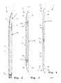
Fig. 2 ist ein Ausführungsbeispiel der erfindungsgemäßen Leuchte 5a dargestellt. Hier gezeigt ist eine Schnittansicht. Die Lichtabstrahlrichtung ist dabei nach rechts. Die Leuchte 5a beinhaltet dabei ein Gehäuse 13, beispielsweise ein Aluminiumgehäuse. Das Gehäuse 13 umfasst dabei ein Profil 10, vorzugsweise ein Aluminiumprofil, mittels welchem die Leuchte 5a an der Halterung 4 ausFig. 1 befestigt werden kann. Innerhalb des Gehäuses 13 ist dabei ein Leuchtmittel 11, bevorzugt eine LED oder ein LED-Modul mit mehreren LEDs angeordnet. Darüber hinaus ist innerhalb des Gehäuses 13 ein (flächiger) Lichtleiter 12 mit flächiger Lichtabgabeseite FA angeordnet. Weiterhin umfasst das Gehäuse 13 einen Reflektor 16 und ein Lamellenraster 5. Der Reflektor 16 kann dabei als Teil des Gehäuses 13 ausgebildet oder lösbar mit dem Gehäuse 13 verbunden sein. - Von dem Leuchtmittel 11 abgestrahltes Licht tritt in den Lichtleiter 12 ein. Der Lichtleiter 12 leitet das Licht und strahlt es in Abstrahlrichtung - nach rechts - ab. Um die diffuse Lichtabstrahlung durch den Lichtleiter 12 zu fördern, weist der Lichtleiter 12 vorzugsweise ein Auskoppelelement bzw. eine Auskoppelstruktur, wie eine aufgeraute Oberfläche oder eine strukturierte Oberfläche oder eine Auskoppelschicht oder eine (wenigstens teilweise) reflektierende Oberfläche auf seiner der Lichtabgabeseite A zugewandten und/oder abgewandten Seite bzw. Oberfläche auf. Zur Verbesserung der Lichtausbeute ist dabei die Innenseite des Gehäuses 13 im Bereich des Lichtleiters 12 - also dort, wo Gehäuseinnenseite und Lichtleiter in flächigem Kontakt stehen - reflektierend ausgebildet, so dass von dem Leuchtmittel 11 erzeugtes und gegen das Gehäuse 13 strahlendes Licht erneut zurück in den Lichtleiter 12 reflektiert wird.
- Das Leuchtmittel 11 ist dabei an einer ersten Stirnseite des Lichtleiters 12 angeordnet. An einer zweiten Stirnseite des Lichtleiters 12, welche vorzugsweise auf einer der ersten Stirnseite gegenüberliegenden Seite des Lichtleiters 12 angeordnet ist, befindet sich vorzugsweise eine den Lichtaustritt fördernde Oberflächenstruktur 14, bevorzugt eine polierte Oberflächenstruktur. Dies sorgt dafür, dass an der zweiten Stirnfläche aus dem Lichtleiter 12 austretendes Restlicht von dem Reflektor 16 in Abstrahlrichtung reflektiert werden kann.
- Der Reflektor 16 erzeugt somit gerichtetes Licht in Abstrahlrichtung, während der Lichtleiter 12 diffuses Licht in Abstrahlrichtung erzeugt. Somit kann sowohl diffuses als auch gerichtetes Licht über die Lichtabgabeseite A der Leuchte 5a abgegeben werden. Zur Vermeidung von Blendungseffekten weist der Reflektor 16 darüber hinaus vorzugsweise ein Lamellenraster 15 auf.
- Die Reflektoren sind dabei in sämtlichen Ausführungsbeispielen optional austauschbar gestaltet, sodass die Richtcharakteristik durch Einsatz eines geeigneten Reflektors eingestellt werden kann.
- In
Fig. 3 ist ein weiteres Ausführungsbeispiel der erfindungsgemäßen Leuchte 5b dargestellt. Die Leuchte 5b weist dabei ein Gehäuse 23 und einen Lichtleiter 22 auf. Weiterhin weist die Leuchte 5b an einer ersten Stirnseite des Lichtstirnseite des Lichtleiters 22 ein erstes Leuchtmittel 21a und an einer zweiten Stirnseite des Lichtleiters 22 ein zweites Leuchtmittel 21b auf. Auch bei diesen Leuchtmitteln 21a, 21b handelt es sich jeweils bevorzugt um zumindest eine LED oder ein LED-Modul mit mehreren LEDs. Die Leuchte 5b weist weiterhin auf der ersten Stirnseite des Lichtleiters 22 eine den Lichtaustritt fördernde Oberfläche 24b und auf der zweiten Stirnseite des Lichtleiters 22 eine den Lichtaustritt fördernde Oberfläche 24a auf. Auch hierbei handelt es sich bevorzugt um polierte Oberflächen. Darüber hinaus weist die Leuchte 5b auf beiden Seiten des Lichtleiters 22 jeweils einen Reflektor 26a, 26b vorzugsweise mit jeweils einem Lamellenelement 25a, 25b auf. - Im Betrieb wird von beiden Leuchtmitteln 21a und 21b Licht erzeugt und in entgegengesetzter Richtung in den Lichtleiter 22 eingestrahlt. Der Lichtleiter 22 strahlt dabei diffuses Licht in Abstrahlrichtung ab. Auch hier ist bevorzugt die Innenseite des Gehäuses 23 im Bereich des Lichtleiters 22 reflektierend ausgebildet. Licht des ersten Leuchtmittels 21a, welches die zweite Stirnseite des Lichtleiters 22 erreicht, verlässt dort den Lichtleiter über die Oberfläche 24a und wird von dem Reflektor 26a als gerichtetes Licht in Abstrahlrichtung reflektiert. Von dem zweiten Leuchtmittel 21b erzeugtes Licht, welches durch den Lichtleiter 22 die Oberfläche 24b erreicht, verlässt dort den Lichtleiter 22 und wird von dem Reflektor 26b in Abstrahlrichtung als gerichtetes Licht reflektiert. Damit eine nennenswerte Lichtausbeute des gerichteten Lichts erreicht werden kann, sind dabei die Leuchtmittel 21a und 21b so ausgeführt, dass sie lediglich einen geringen Teil des Querschnitts der Leuchte 5b einnehmen. D.h. ein nennenswerter Teil des aus dem Lichtleiter 22 an den Oberflächen 24a und 24b austretenden Lichts kann die Leuchtmittel 21a und 21b passieren und von den Reflektoren 26a und 26b reflektiert werden.
- In
Fig. 4 sind zwei Leuchten 5c, 5d gemäß eines weiteren Ausführungsbeispiels dargestellt. Die Leuchten 5c, 5d bilden eine Leuchtenanordnung 6. Die Leuchte 5c umfasst dabei ein Profil 30, ein Leuchtmittel 31a, ein optimales Gehäuse 33a, einen Lichtleiter 32a, eine den Lichtaustritt fördernde optimale Oberfläche 34a, einen Reflektor 36a und ein optimales Lamellenelement 35a. Die Funktion entspricht dabei der Funktion der Leuchte 5a ausFig. 2 . Die Leuchte 5c teilt sich dabei ein gemeinsames Profil 30, vorzugsweise ein Aluminiumprofil mit der Leuchte 5d, welche über ein Leuchtmittel 31b, ein Gehäuse 33b, einen Lichtleiter 32b, einen Reflektor 36b, eine den Lichtaustritt fördernde Oberfläche 34b und ein Lamellenelement 35b verfügt. Auch die Funktion der Leuchte 5d entspricht dabei der Funktion der Leuchte 5a ausFig. 2 . Durch die "Rücken-an-Rücken"-Montage zweier Leuchten 5c, 5d wird die Lichtleistung der Leuchtenanordnung gegenüber der Lichtleistung einer einzigen Leuchte verdoppelt. Gleichzeitig wird ein symmetrischer Aufbau erreicht, welcher für zahlreiche Anwendungen wünschenswert ist. Darüber hinaus wird der Effizienzverlust, wie er bei einer Leuchte 5b gemäßFig. 3 aufgrund der Verdeckung eines Teils der Stirnseiten des Lichtleiters 22 auftritt, vermieden. - Die Erfindung ist dabei nicht auf das dargestellte Ausführungsbeispiel beschränkt. Neben LEDs als Leuchtmitteln können auch herkömmliche Glühlampen, Halogenlampen, Leuchtstoffröhren, etc. eingesetzt werden. Auch kann anstatt eines Lamellenrasters ein alternatives optimales Entblendungselement genutzt werden.
- Alle vorstehend beschriebenen Merkmale oder in den Figuren gezeigten Merkmale sind im Rahmen der Erfindung beliebig vorteilhaft miteinander kombinierbar, soweit sie vom Gegenstand der folgenden Ansprüche erfasst sind und insbesondere eine kombinierte Lichtabgabe von diffusem und gerichtetem Licht ermöglichen.
Claims (10)
- Leuchte (5, 5a, 5b, 5c, 5d) mit einem flächigen Lichtleiter (12, 22, 32a, 32b), einem Reflektor (16, 26a, 26b, 36a, 36b) und einem Leuchtmittel (11, 21a, 21b, 31a, 31b), bevorzugt zumindest einer LED,
wobei das Leuchtmittel (11, 21a, 21b, 31a, 31b) derart an einer ersten Stirnseite des Lichtleiters (12, 22, 32a, 32b) angeordnet ist, dass von dem Leuchtmittel (11, 21a, 21b, 31a, 31b) erzeugtes Licht an der ersten Stirnseite in den Lichtleiter (12, 22, 32a, 32b) eintritt und von dem Lichtleiter (12, 22, 32a, 32b) diffus gestreut über eine flächige Lichtabgabeseite (FA) des Lichtleiters (12, 22, 32a, 32b) einer Lichtabgabeseite (A) der Leuchte (5, 5a, 5b, 5c, 5d) abgegeben wird,
wobei der Reflektor (16, 26a, 26b, 36a, 36b) derart an einer, der ersten Stirnseite vorzugsweise gegenübergelegenen zweiten Stirnseite des Lichtleiters (12, 22, 32a, 32b) angeordnet ist, dass an der zweiten Stirnseite aus dem Lichtleiter (12, 22, 32a, 32b) austretendes Licht des Leuchtmittels (11, 21a, 21b, 31a, 31b) von dem Reflektor (16, 26a, 26b, 36a, 36b) reflektiert und gerichtet über die Lichtabgabeseite (A) der Leuchte (5, 5a, 5b, 5c, 5d) wird. - Leuchte (5, 5a, 5b, 5c, 5d) nach Anspruch 1,
dadurch gekennzeichnet,
dass die Leuchte (5, 5a, 5b, 5c, 5d) über ein Leuchtengehäuse (13, 23, 33a, 33b) verfügt, in welchem der Lichtleiter (12, 22, 32a, 32b), das Leuchtmittel (11, 21a, 21b, 31a, 31b) und der Reflektor (16, 26a, 26b, 36a, 36b) angeordnet sind, und
dass eine Innenseite des Leuchtengehäuses (13, 23, 33a, 33b) im Bereich des Lichtleiters (12, 22, 32a, 32b) derart reflektierend ausgebildet ist, dass sie von dem Lichtleiter (12, 22, 32a, 32b) abgestrahltes Licht des Leuchtmittels (11, 21a, 21b, 31a, 31b) zurück in den Lichtleiter (12, 22, 32a, 32b) reflektiert. - Leuchte (5, 5a, 5b, 5c, 5d) nach Anspruch 1 oder 2,
dadurch gekennzeichnet,
dass der Lichtleiter (12, 22, 32a, 32b) auf seiner der Lichtabgabeseite (FA) zugewandten oder abgewandten Seite ein Auskoppelelement, wie eine aufgeraute Oberfläche oder eine strukturierte Oberfläche oder eine Auskoppelschicht oder eine reflektierende Oberfläche, aufweist, und/oder dass der Lichtleiter (12, 22, 32a, 32b) an der zweiten Stirnseite eine, den Lichtaustritt fördernde Oberflächenstruktur, bevorzugt eine polierte Oberfläche (14, 24a, 24b, 34a, 34b) aufweist. - Leuchte (5, 5a, 5b, 5c, 5d) nach einem der Ansprüche 1 bis 3,
dadurch gekennzeichnet,
dass der Reflektor (16, 26a, 26b, 36a, 36b) ein Lamellenraster aufweist, welches ausgebildet ist, um eine Entblendung des gerichtet seitlich reflektierten Lichts durchzuführen. - Leuchte (5a, 5b, 5c, 5d) nach einem der Ansprüche 1 bis 4,
dadurch gekennzeichnet,
dass die Leuchte (5b) ein weiteres Leuchtmittel (21b), bevorzugt zumindest eine LED, aufweist, welches an der zweiten Stirnseite des Lichtleiters (22) angebracht ist, dass die Leuchte (5b) einen weiteren Reflektor (26b) aufweist, welcher an der ersten Stirnseite des Lichtleiters (22) angebracht ist. - Leuchte (5b) nach Anspruch 5,
dadurch gekennzeichnet,
dass das weitere Leuchtmittel (21b) derart an der zweiten Stirnseite des Lichtleiters (22) angeordnet ist, dass von dem weiteren Leuchtmittel (21b) erzeugtes Licht an der zweiten Stirnseite in den Lichtleiter (22) eintritt und von dem Lichtleiter (22) diffus gestreut über die flächige Lichtabgabeseite (FA) abgegeben wird,
dass der weitere Reflektor (26b) derart an der ersten Stirnseite angeordnet ist, dass an der ersten Stirnseite aus dem Lichtleiter (22) austretendes Licht des weiteren Leuchtmittels (21b) von dem weiteren Reflektor (26b) gerichtet seitlich reflektiert und gerichtet über die Lichtabgabeseite (A) der Leuchte (5b) abgegeben wird. - Leuchte (5b) nach Anspruch 5 oder 6,
dadurch gekennzeichnet,
dass die erste Stirnseite von dem Leuchtmittel (21a) lediglich teilweise verdeckt ist, sodass von dem weiteren Leuchtmittel (21b) in den Lichtleiter (22) abgestrahltes und an der ersten Stirnseite austretendes Licht zumindest teilweise von dem weiteren Reflektor (26b) reflektiert und gerichtet über die Lichtabgabeseite (A) der Leuchte (5b) abgegeben wird, und
dass die zweite Stirnseite von dem weiteren Leuchtmittel (21b) lediglich teilweise verdeckt ist, sodass von dem Leuchtmittel (21a) in den Lichtleiter (22) abgestrahltes und an der zweiten Stirnseite austretendes Licht zumindest teilweise von dem Reflektor (26a) und gerichtet über die Lichtabgabeseite (A) der Leuchte (5b) abgegeben reflektiert wird. - Leuchte (5, 5a, 5b, 5c, 5d) nach einem der Ansprüche 1 bis 7,
dadurch gekennzeichnet,
dass die Leuchte (5, 5a, 5b, 5c, 5d) derart aufgebaut ist, dass der Reflektor (16, 26a, 26b, 36a, 36b) und/oder der weitere Reflektor (16, 26a, 26b, 36a, 36b) austauschbar sind, und
dass mittels unterschiedlich gestalteter Reflektoren (16, 26a, 26b, 36a, 36b) unterschiedliche Richtcharakteristiken des von den Reflektoren reflektierten Lichts realisierbar sind. - Leuchtenanordnung (6) mit zwei Leuchten (5c, 5d) nach einem der Ansprüche 1 bis 4,
dadurch gekennzeichnet,
dass die zwei Leuchten (5c, 5d) in einer Ebene derart angeordnet sind, dass die Leuchtmittel (31a, 31b) der Leuchten (5c, 5d) Licht in entgegengesetzte Richtungen abstrahlen, und dass die Lichtleiter (32a, 32b) und Reflektoren (36a, 36b) der Leuchten (5c, 5d) Licht auf einer gemeinsamen Seite der Ebene ausgeben. - Leuchtensystem (1) mit einer Stromschiene (2), einer Elektronikeinheit (3), einer Halterung (4) und einer Leuchte (5) nach einem der Ansprüche 1 bis 8 oder einer Leuchtenanordnung (6) nach Anspruch 9,
dadurch gekennzeichnet,
dass die Stromschiene (2) die Elektronikeinheit (3) trägt, und
dass die Elektronikeinheit (3) mittels der Halterung (4) die Leuchte (5) bzw. Leuchtenanordnung (6) trägt.
Applications Claiming Priority (1)
| Application Number | Priority Date | Filing Date | Title |
|---|---|---|---|
| DE202014103671.7U DE202014103671U1 (de) | 2014-08-07 | 2014-08-07 | Flächige Ausstellungsleuchte |
Publications (2)
| Publication Number | Publication Date |
|---|---|
| EP2982899A1 true EP2982899A1 (de) | 2016-02-10 |
| EP2982899B1 EP2982899B1 (de) | 2017-05-17 |
Family
ID=53835909
Family Applications (1)
| Application Number | Title | Priority Date | Filing Date |
|---|---|---|---|
| EP15179811.3A Not-in-force EP2982899B1 (de) | 2014-08-07 | 2015-08-05 | Flächige ausstellungsleuchte |
Country Status (3)
| Country | Link |
|---|---|
| EP (1) | EP2982899B1 (de) |
| AT (1) | AT16995U1 (de) |
| DE (1) | DE202014103671U1 (de) |
Cited By (2)
| Publication number | Priority date | Publication date | Assignee | Title |
|---|---|---|---|---|
| US20220221642A1 (en) * | 2019-09-10 | 2022-07-14 | HLI Solutions, Inc. | Canopy luminaire |
| WO2024041889A1 (en) * | 2022-08-22 | 2024-02-29 | Signify Holding B.V. | A track-lighting system |
Families Citing this family (1)
| Publication number | Priority date | Publication date | Assignee | Title |
|---|---|---|---|---|
| DE202018102168U1 (de) * | 2018-04-19 | 2019-07-22 | Zumtobel Lighting Gmbh | Flache LED-Leuchte |
Citations (7)
| Publication number | Priority date | Publication date | Assignee | Title |
|---|---|---|---|---|
| DE4205137A1 (de) * | 1992-02-20 | 1993-08-26 | Willing Gmbh Dr Ing | Scheibenfoermige leuchte |
| EP0697560A1 (de) * | 1994-08-17 | 1996-02-21 | Siemens Aktiengesellschaft | Langgestreckte Innenleuchte für arbeitsplatzorientierte Beleuchtung |
| US20040213003A1 (en) * | 2003-04-23 | 2004-10-28 | Bruce Lauderdale | Suspended ceiling lighting system incorporating T-bar component |
| DE202007003819U1 (de) | 2007-03-08 | 2008-07-10 | Pöllet, Wilfried | Leuchtendes plattenförmiges Einrichtungs-Element |
| WO2012152536A1 (en) * | 2011-05-12 | 2012-11-15 | Osram Ag | A lighting apparatus and a lighting system having the lighting apparatus |
| WO2013128761A1 (ja) * | 2012-02-29 | 2013-09-06 | シャープ株式会社 | 照明モジュールおよびそれを備えた照明装置 |
| WO2014021456A1 (ja) * | 2012-08-02 | 2014-02-06 | シャープ株式会社 | 照明装置 |
Family Cites Families (7)
| Publication number | Priority date | Publication date | Assignee | Title |
|---|---|---|---|---|
| DE19910273C2 (de) * | 1999-03-08 | 2002-12-19 | Poellet Wilfried | Beleuchtungsanordnung |
| DE19942513A1 (de) * | 1999-09-07 | 2001-03-08 | Gerhard Karl | Leuchtkörper für durchleuchtungsfähige Bilder |
| DE10229064B4 (de) * | 2002-06-28 | 2008-08-14 | Osram Gesellschaft mit beschränkter Haftung | Flüssigkristall-Display |
| DE102004042821A1 (de) * | 2004-09-03 | 2006-03-30 | Engel, Hartmut S. | Strahler |
| CZ307329B6 (cs) * | 2006-05-15 | 2018-06-13 | Varroc Lighting Systems, s.r.o. | Světelné zařízení pro motorové vozidlo, obsahující planární světlovod |
| DE102008060874A1 (de) * | 2008-12-09 | 2010-06-10 | Manfred Grimm | Leuchte |
| DE102014102355A1 (de) * | 2014-02-24 | 2015-08-27 | Hella Kgaa Hueck & Co. | Beleuchtungsvorrichtung für Fahrzeuge |
-
2014
- 2014-08-07 DE DE202014103671.7U patent/DE202014103671U1/de not_active Expired - Lifetime
- 2014-09-08 AT ATGM316/2014U patent/AT16995U1/de not_active IP Right Cessation
-
2015
- 2015-08-05 EP EP15179811.3A patent/EP2982899B1/de not_active Not-in-force
Patent Citations (7)
| Publication number | Priority date | Publication date | Assignee | Title |
|---|---|---|---|---|
| DE4205137A1 (de) * | 1992-02-20 | 1993-08-26 | Willing Gmbh Dr Ing | Scheibenfoermige leuchte |
| EP0697560A1 (de) * | 1994-08-17 | 1996-02-21 | Siemens Aktiengesellschaft | Langgestreckte Innenleuchte für arbeitsplatzorientierte Beleuchtung |
| US20040213003A1 (en) * | 2003-04-23 | 2004-10-28 | Bruce Lauderdale | Suspended ceiling lighting system incorporating T-bar component |
| DE202007003819U1 (de) | 2007-03-08 | 2008-07-10 | Pöllet, Wilfried | Leuchtendes plattenförmiges Einrichtungs-Element |
| WO2012152536A1 (en) * | 2011-05-12 | 2012-11-15 | Osram Ag | A lighting apparatus and a lighting system having the lighting apparatus |
| WO2013128761A1 (ja) * | 2012-02-29 | 2013-09-06 | シャープ株式会社 | 照明モジュールおよびそれを備えた照明装置 |
| WO2014021456A1 (ja) * | 2012-08-02 | 2014-02-06 | シャープ株式会社 | 照明装置 |
Cited By (3)
| Publication number | Priority date | Publication date | Assignee | Title |
|---|---|---|---|---|
| US20220221642A1 (en) * | 2019-09-10 | 2022-07-14 | HLI Solutions, Inc. | Canopy luminaire |
| US11686894B2 (en) * | 2019-09-10 | 2023-06-27 | HLI Solutions, Inc. | Canopy luminaire |
| WO2024041889A1 (en) * | 2022-08-22 | 2024-02-29 | Signify Holding B.V. | A track-lighting system |
Also Published As
| Publication number | Publication date |
|---|---|
| AT16995U1 (de) | 2021-02-15 |
| DE202014103671U1 (de) | 2015-11-10 |
| EP2982899B1 (de) | 2017-05-17 |
Similar Documents
| Publication | Publication Date | Title |
|---|---|---|
| EP1378771B1 (de) | Innenraumleuchte | |
| EP2986893B1 (de) | Leuchte | |
| DE102004002251A1 (de) | Leuchte mit verschiedenfarbigen Lichtquellen sowie einer Lichtleiterplatte zum Abgeben von Mischlicht | |
| DE102010062454A1 (de) | Anordnung zur Lichtabgabe | |
| EP2360427A2 (de) | Drei-Zonen Reflektor | |
| DE102014004472B4 (de) | Leuchtmodul aufweisend ein optisches Element | |
| EP3186543B1 (de) | Rahmenlose pendelleuchte | |
| EP3037719A1 (de) | Led-linsenkörper zur erzeugung eines direkt- und indirektlichtanteils | |
| EP2982899B1 (de) | Flächige ausstellungsleuchte | |
| DE102010041477A1 (de) | Anordnung zur Lichtabgabe | |
| EP3748223B1 (de) | Anordnung zur lichtabgabe | |
| EP2895790B1 (de) | Rasterleuchte mit led-lichtquellen | |
| DE102012217293A1 (de) | LED-Leuchte mit Lichtleiterplatte | |
| EP2426408B1 (de) | Flexible Beleuchtungsanordnung | |
| WO2016166203A1 (de) | Optisches system sowie anordnung zur lichtabgabe | |
| DE102023121516A1 (de) | Beleuchtungsvorrichtung | |
| EP2989378B1 (de) | Led-leuchte mit unterschiedlich einstellbaren lichtverteilungen | |
| AT11430U1 (de) | Leuchte | |
| AT17328U1 (de) | Flache LED-Leuchte | |
| DE102018119606A1 (de) | Optisches Element für eine Leuchte, insbesondere Büroleuchte, sowie Leuchte | |
| DE102012211451B4 (de) | Leuchte mit zumindest einer leuchtstofflampe und einer leuchtdiodenanordnung sowie display-hinterleuchtungsvorrichtung mit zumindest einer derartigen leuchte | |
| AT13883U1 (de) | Leuchte mit leuchtendem Gehäuse | |
| WO2021254682A1 (de) | Anordnung zur lichtabgabe und leuchte | |
| DE102005029954A1 (de) | Leuchte mit einem Leuchtengehäuse aus einem thermoplastischen Kunststoff | |
| DE202018103783U1 (de) | Leuchte |
Legal Events
| Date | Code | Title | Description |
|---|---|---|---|
| PUAI | Public reference made under article 153(3) epc to a published international application that has entered the european phase |
Free format text: ORIGINAL CODE: 0009012 |
|
| AK | Designated contracting states |
Kind code of ref document: A1 Designated state(s): AL AT BE BG CH CY CZ DE DK EE ES FI FR GB GR HR HU IE IS IT LI LT LU LV MC MK MT NL NO PL PT RO RS SE SI SK SM TR |
|
| AX | Request for extension of the european patent |
Extension state: BA ME |
|
| 17P | Request for examination filed |
Effective date: 20160425 |
|
| RBV | Designated contracting states (corrected) |
Designated state(s): AL AT BE BG CH CY CZ DE DK EE ES FI FR GB GR HR HU IE IS IT LI LT LU LV MC MK MT NL NO PL PT RO RS SE SI SK SM TR |
|
| GRAP | Despatch of communication of intention to grant a patent |
Free format text: ORIGINAL CODE: EPIDOSNIGR1 |
|
| STAA | Information on the status of an ep patent application or granted ep patent |
Free format text: STATUS: GRANT OF PATENT IS INTENDED |
|
| INTG | Intention to grant announced |
Effective date: 20161215 |
|
| GRAS | Grant fee paid |
Free format text: ORIGINAL CODE: EPIDOSNIGR3 |
|
| GRAA | (expected) grant |
Free format text: ORIGINAL CODE: 0009210 |
|
| STAA | Information on the status of an ep patent application or granted ep patent |
Free format text: STATUS: THE PATENT HAS BEEN GRANTED |
|
| AK | Designated contracting states |
Kind code of ref document: B1 Designated state(s): AL AT BE BG CH CY CZ DE DK EE ES FI FR GB GR HR HU IE IS IT LI LT LU LV MC MK MT NL NO PL PT RO RS SE SI SK SM TR |
|
| REG | Reference to a national code |
Ref country code: GB Ref legal event code: FG4D Free format text: NOT ENGLISH |
|
| REG | Reference to a national code |
Ref country code: CH Ref legal event code: EP Ref country code: CH Ref legal event code: NV Representative=s name: FELBER UND PARTNER AG, CH |
|
| REG | Reference to a national code |
Ref country code: IE Ref legal event code: FG4D Free format text: LANGUAGE OF EP DOCUMENT: GERMAN |
|
| REG | Reference to a national code |
Ref country code: AT Ref legal event code: REF Ref document number: 894798 Country of ref document: AT Kind code of ref document: T Effective date: 20170615 |
|
| REG | Reference to a national code |
Ref country code: DE Ref legal event code: R096 Ref document number: 502015001067 Country of ref document: DE |
|
| REG | Reference to a national code |
Ref country code: FR Ref legal event code: PLFP Year of fee payment: 3 |
|
| REG | Reference to a national code |
Ref country code: NL Ref legal event code: MP Effective date: 20170517 |
|
| REG | Reference to a national code |
Ref country code: LT Ref legal event code: MG4D |
|
| PG25 | Lapsed in a contracting state [announced via postgrant information from national office to epo] |
Ref country code: LT Free format text: LAPSE BECAUSE OF FAILURE TO SUBMIT A TRANSLATION OF THE DESCRIPTION OR TO PAY THE FEE WITHIN THE PRESCRIBED TIME-LIMIT Effective date: 20170517 Ref country code: NO Free format text: LAPSE BECAUSE OF FAILURE TO SUBMIT A TRANSLATION OF THE DESCRIPTION OR TO PAY THE FEE WITHIN THE PRESCRIBED TIME-LIMIT Effective date: 20170817 Ref country code: FI Free format text: LAPSE BECAUSE OF FAILURE TO SUBMIT A TRANSLATION OF THE DESCRIPTION OR TO PAY THE FEE WITHIN THE PRESCRIBED TIME-LIMIT Effective date: 20170517 Ref country code: GR Free format text: LAPSE BECAUSE OF FAILURE TO SUBMIT A TRANSLATION OF THE DESCRIPTION OR TO PAY THE FEE WITHIN THE PRESCRIBED TIME-LIMIT Effective date: 20170818 Ref country code: ES Free format text: LAPSE BECAUSE OF FAILURE TO SUBMIT A TRANSLATION OF THE DESCRIPTION OR TO PAY THE FEE WITHIN THE PRESCRIBED TIME-LIMIT Effective date: 20170517 Ref country code: HR Free format text: LAPSE BECAUSE OF FAILURE TO SUBMIT A TRANSLATION OF THE DESCRIPTION OR TO PAY THE FEE WITHIN THE PRESCRIBED TIME-LIMIT Effective date: 20170517 |
|
| PG25 | Lapsed in a contracting state [announced via postgrant information from national office to epo] |
Ref country code: RS Free format text: LAPSE BECAUSE OF FAILURE TO SUBMIT A TRANSLATION OF THE DESCRIPTION OR TO PAY THE FEE WITHIN THE PRESCRIBED TIME-LIMIT Effective date: 20170517 Ref country code: BG Free format text: LAPSE BECAUSE OF FAILURE TO SUBMIT A TRANSLATION OF THE DESCRIPTION OR TO PAY THE FEE WITHIN THE PRESCRIBED TIME-LIMIT Effective date: 20170817 Ref country code: NL Free format text: LAPSE BECAUSE OF FAILURE TO SUBMIT A TRANSLATION OF THE DESCRIPTION OR TO PAY THE FEE WITHIN THE PRESCRIBED TIME-LIMIT Effective date: 20170517 Ref country code: SE Free format text: LAPSE BECAUSE OF FAILURE TO SUBMIT A TRANSLATION OF THE DESCRIPTION OR TO PAY THE FEE WITHIN THE PRESCRIBED TIME-LIMIT Effective date: 20170517 Ref country code: LV Free format text: LAPSE BECAUSE OF FAILURE TO SUBMIT A TRANSLATION OF THE DESCRIPTION OR TO PAY THE FEE WITHIN THE PRESCRIBED TIME-LIMIT Effective date: 20170517 Ref country code: PL Free format text: LAPSE BECAUSE OF FAILURE TO SUBMIT A TRANSLATION OF THE DESCRIPTION OR TO PAY THE FEE WITHIN THE PRESCRIBED TIME-LIMIT Effective date: 20170517 Ref country code: IS Free format text: LAPSE BECAUSE OF FAILURE TO SUBMIT A TRANSLATION OF THE DESCRIPTION OR TO PAY THE FEE WITHIN THE PRESCRIBED TIME-LIMIT Effective date: 20170917 |
|
| PG25 | Lapsed in a contracting state [announced via postgrant information from national office to epo] |
Ref country code: EE Free format text: LAPSE BECAUSE OF FAILURE TO SUBMIT A TRANSLATION OF THE DESCRIPTION OR TO PAY THE FEE WITHIN THE PRESCRIBED TIME-LIMIT Effective date: 20170517 Ref country code: DK Free format text: LAPSE BECAUSE OF FAILURE TO SUBMIT A TRANSLATION OF THE DESCRIPTION OR TO PAY THE FEE WITHIN THE PRESCRIBED TIME-LIMIT Effective date: 20170517 Ref country code: SK Free format text: LAPSE BECAUSE OF FAILURE TO SUBMIT A TRANSLATION OF THE DESCRIPTION OR TO PAY THE FEE WITHIN THE PRESCRIBED TIME-LIMIT Effective date: 20170517 Ref country code: CZ Free format text: LAPSE BECAUSE OF FAILURE TO SUBMIT A TRANSLATION OF THE DESCRIPTION OR TO PAY THE FEE WITHIN THE PRESCRIBED TIME-LIMIT Effective date: 20170517 Ref country code: RO Free format text: LAPSE BECAUSE OF FAILURE TO SUBMIT A TRANSLATION OF THE DESCRIPTION OR TO PAY THE FEE WITHIN THE PRESCRIBED TIME-LIMIT Effective date: 20170517 |
|
| REG | Reference to a national code |
Ref country code: DE Ref legal event code: R097 Ref document number: 502015001067 Country of ref document: DE |
|
| PG25 | Lapsed in a contracting state [announced via postgrant information from national office to epo] |
Ref country code: SM Free format text: LAPSE BECAUSE OF FAILURE TO SUBMIT A TRANSLATION OF THE DESCRIPTION OR TO PAY THE FEE WITHIN THE PRESCRIBED TIME-LIMIT Effective date: 20170517 Ref country code: IT Free format text: LAPSE BECAUSE OF FAILURE TO SUBMIT A TRANSLATION OF THE DESCRIPTION OR TO PAY THE FEE WITHIN THE PRESCRIBED TIME-LIMIT Effective date: 20170517 |
|
| PLBE | No opposition filed within time limit |
Free format text: ORIGINAL CODE: 0009261 |
|
| STAA | Information on the status of an ep patent application or granted ep patent |
Free format text: STATUS: NO OPPOSITION FILED WITHIN TIME LIMIT |
|
| PG25 | Lapsed in a contracting state [announced via postgrant information from national office to epo] |
Ref country code: MC Free format text: LAPSE BECAUSE OF FAILURE TO SUBMIT A TRANSLATION OF THE DESCRIPTION OR TO PAY THE FEE WITHIN THE PRESCRIBED TIME-LIMIT Effective date: 20170517 |
|
| 26N | No opposition filed |
Effective date: 20180220 |
|
| REG | Reference to a national code |
Ref country code: BE Ref legal event code: MM Effective date: 20170831 |
|
| REG | Reference to a national code |
Ref country code: IE Ref legal event code: MM4A |
|
| PG25 | Lapsed in a contracting state [announced via postgrant information from national office to epo] |
Ref country code: SI Free format text: LAPSE BECAUSE OF FAILURE TO SUBMIT A TRANSLATION OF THE DESCRIPTION OR TO PAY THE FEE WITHIN THE PRESCRIBED TIME-LIMIT Effective date: 20170517 |
|
| PG25 | Lapsed in a contracting state [announced via postgrant information from national office to epo] |
Ref country code: LU Free format text: LAPSE BECAUSE OF NON-PAYMENT OF DUE FEES Effective date: 20170805 |
|
| PG25 | Lapsed in a contracting state [announced via postgrant information from national office to epo] |
Ref country code: IE Free format text: LAPSE BECAUSE OF NON-PAYMENT OF DUE FEES Effective date: 20170805 |
|
| REG | Reference to a national code |
Ref country code: FR Ref legal event code: PLFP Year of fee payment: 4 |
|
| PG25 | Lapsed in a contracting state [announced via postgrant information from national office to epo] |
Ref country code: BE Free format text: LAPSE BECAUSE OF NON-PAYMENT OF DUE FEES Effective date: 20170831 |
|
| PG25 | Lapsed in a contracting state [announced via postgrant information from national office to epo] |
Ref country code: MT Free format text: LAPSE BECAUSE OF FAILURE TO SUBMIT A TRANSLATION OF THE DESCRIPTION OR TO PAY THE FEE WITHIN THE PRESCRIBED TIME-LIMIT Effective date: 20170517 |
|
| PG25 | Lapsed in a contracting state [announced via postgrant information from national office to epo] |
Ref country code: HU Free format text: LAPSE BECAUSE OF FAILURE TO SUBMIT A TRANSLATION OF THE DESCRIPTION OR TO PAY THE FEE WITHIN THE PRESCRIBED TIME-LIMIT; INVALID AB INITIO Effective date: 20150805 |
|
| PG25 | Lapsed in a contracting state [announced via postgrant information from national office to epo] |
Ref country code: CY Free format text: LAPSE BECAUSE OF FAILURE TO SUBMIT A TRANSLATION OF THE DESCRIPTION OR TO PAY THE FEE WITHIN THE PRESCRIBED TIME-LIMIT Effective date: 20170517 |
|
| PGFP | Annual fee paid to national office [announced via postgrant information from national office to epo] |
Ref country code: FR Payment date: 20190827 Year of fee payment: 5 |
|
| PG25 | Lapsed in a contracting state [announced via postgrant information from national office to epo] |
Ref country code: MK Free format text: LAPSE BECAUSE OF FAILURE TO SUBMIT A TRANSLATION OF THE DESCRIPTION OR TO PAY THE FEE WITHIN THE PRESCRIBED TIME-LIMIT Effective date: 20170517 |
|
| PGFP | Annual fee paid to national office [announced via postgrant information from national office to epo] |
Ref country code: CH Payment date: 20190827 Year of fee payment: 5 |
|
| PG25 | Lapsed in a contracting state [announced via postgrant information from national office to epo] |
Ref country code: TR Free format text: LAPSE BECAUSE OF FAILURE TO SUBMIT A TRANSLATION OF THE DESCRIPTION OR TO PAY THE FEE WITHIN THE PRESCRIBED TIME-LIMIT Effective date: 20170517 |
|
| PG25 | Lapsed in a contracting state [announced via postgrant information from national office to epo] |
Ref country code: PT Free format text: LAPSE BECAUSE OF FAILURE TO SUBMIT A TRANSLATION OF THE DESCRIPTION OR TO PAY THE FEE WITHIN THE PRESCRIBED TIME-LIMIT Effective date: 20170517 |
|
| PG25 | Lapsed in a contracting state [announced via postgrant information from national office to epo] |
Ref country code: AL Free format text: LAPSE BECAUSE OF FAILURE TO SUBMIT A TRANSLATION OF THE DESCRIPTION OR TO PAY THE FEE WITHIN THE PRESCRIBED TIME-LIMIT Effective date: 20170517 |
|
| REG | Reference to a national code |
Ref country code: CH Ref legal event code: PL |
|
| PG25 | Lapsed in a contracting state [announced via postgrant information from national office to epo] |
Ref country code: CH Free format text: LAPSE BECAUSE OF NON-PAYMENT OF DUE FEES Effective date: 20200831 Ref country code: LI Free format text: LAPSE BECAUSE OF NON-PAYMENT OF DUE FEES Effective date: 20200831 |
|
| PG25 | Lapsed in a contracting state [announced via postgrant information from national office to epo] |
Ref country code: FR Free format text: LAPSE BECAUSE OF NON-PAYMENT OF DUE FEES Effective date: 20200831 |
|
| PGFP | Annual fee paid to national office [announced via postgrant information from national office to epo] |
Ref country code: GB Payment date: 20220823 Year of fee payment: 8 |
|
| P01 | Opt-out of the competence of the unified patent court (upc) registered |
Effective date: 20230530 |
|
| REG | Reference to a national code |
Ref country code: DE Ref legal event code: R084 Ref document number: 502015001067 Country of ref document: DE |
|
| PGFP | Annual fee paid to national office [announced via postgrant information from national office to epo] |
Ref country code: DE Payment date: 20230828 Year of fee payment: 9 |
|
| GBPC | Gb: european patent ceased through non-payment of renewal fee |
Effective date: 20230805 |
|
| PG25 | Lapsed in a contracting state [announced via postgrant information from national office to epo] |
Ref country code: GB Free format text: LAPSE BECAUSE OF NON-PAYMENT OF DUE FEES Effective date: 20230805 |
|
| PG25 | Lapsed in a contracting state [announced via postgrant information from national office to epo] |
Ref country code: GB Free format text: LAPSE BECAUSE OF NON-PAYMENT OF DUE FEES Effective date: 20230805 |
|
| PGFP | Annual fee paid to national office [announced via postgrant information from national office to epo] |
Ref country code: AT Payment date: 20240819 Year of fee payment: 10 |
|
| REG | Reference to a national code |
Ref country code: DE Ref legal event code: R119 Ref document number: 502015001067 Country of ref document: DE |
|
| PG25 | Lapsed in a contracting state [announced via postgrant information from national office to epo] |
Ref country code: DE Free format text: LAPSE BECAUSE OF NON-PAYMENT OF DUE FEES Effective date: 20250301 |
|
| PG25 | Lapsed in a contracting state [announced via postgrant information from national office to epo] |
Ref country code: AT Free format text: LAPSE BECAUSE OF NON-PAYMENT OF DUE FEES Effective date: 20250805 |
|
| REG | Reference to a national code |
Ref country code: AT Ref legal event code: MM01 Ref document number: 894798 Country of ref document: AT Kind code of ref document: T Effective date: 20250805 |