EP2982490A1 - Verfahren zur montage eines vortexgenerators sowie eine montagevorrichtung zur durchführung des verfahrens - Google Patents
Verfahren zur montage eines vortexgenerators sowie eine montagevorrichtung zur durchführung des verfahrens Download PDFInfo
- Publication number
- EP2982490A1 EP2982490A1 EP15177565.7A EP15177565A EP2982490A1 EP 2982490 A1 EP2982490 A1 EP 2982490A1 EP 15177565 A EP15177565 A EP 15177565A EP 2982490 A1 EP2982490 A1 EP 2982490A1
- Authority
- EP
- European Patent Office
- Prior art keywords
- adhesive surface
- adhesive
- attachment
- gap
- rotor blade
- Prior art date
- Legal status (The legal status is an assumption and is not a legal conclusion. Google has not performed a legal analysis and makes no representation as to the accuracy of the status listed.)
- Granted
Links
- 238000000034 method Methods 0.000 title claims abstract description 47
- 239000000853 adhesive Substances 0.000 claims abstract description 177
- 230000001070 adhesive effect Effects 0.000 claims abstract description 177
- 150000001875 compounds Chemical class 0.000 claims abstract description 4
- 238000003825 pressing Methods 0.000 claims description 31
- 230000001681 protective effect Effects 0.000 claims description 30
- 238000002347 injection Methods 0.000 claims description 28
- 239000007924 injection Substances 0.000 claims description 28
- 239000002390 adhesive tape Substances 0.000 claims description 18
- 230000002093 peripheral effect Effects 0.000 claims description 8
- KFZMGEQAYNKOFK-UHFFFAOYSA-N Isopropanol Chemical compound CC(C)O KFZMGEQAYNKOFK-UHFFFAOYSA-N 0.000 description 18
- 239000003570 air Substances 0.000 description 13
- 239000004820 Pressure-sensitive adhesive Substances 0.000 description 9
- 239000007788 liquid Substances 0.000 description 9
- 238000004519 manufacturing process Methods 0.000 description 6
- 238000004026 adhesive bonding Methods 0.000 description 5
- 239000004576 sand Substances 0.000 description 4
- 230000015572 biosynthetic process Effects 0.000 description 3
- 238000004140 cleaning Methods 0.000 description 3
- 239000002131 composite material Substances 0.000 description 3
- 230000001154 acute effect Effects 0.000 description 2
- 239000000428 dust Substances 0.000 description 2
- 239000012535 impurity Substances 0.000 description 2
- 239000000203 mixture Substances 0.000 description 2
- 239000004814 polyurethane Substances 0.000 description 2
- 230000009467 reduction Effects 0.000 description 2
- XLYOFNOQVPJJNP-UHFFFAOYSA-N water Substances O XLYOFNOQVPJJNP-UHFFFAOYSA-N 0.000 description 2
- CERQOIWHTDAKMF-UHFFFAOYSA-M Methacrylate Chemical compound CC(=C)C([O-])=O CERQOIWHTDAKMF-UHFFFAOYSA-M 0.000 description 1
- NIXOWILDQLNWCW-UHFFFAOYSA-N acrylic acid group Chemical group C(C=C)(=O)O NIXOWILDQLNWCW-UHFFFAOYSA-N 0.000 description 1
- 239000012080 ambient air Substances 0.000 description 1
- 238000010276 construction Methods 0.000 description 1
- 229920006332 epoxy adhesive Polymers 0.000 description 1
- 239000004744 fabric Substances 0.000 description 1
- 230000002349 favourable effect Effects 0.000 description 1
- 239000006260 foam Substances 0.000 description 1
- 239000011888 foil Substances 0.000 description 1
- 239000003292 glue Substances 0.000 description 1
- 238000001746 injection moulding Methods 0.000 description 1
- 239000002245 particle Substances 0.000 description 1
- 230000035515 penetration Effects 0.000 description 1
- 239000004033 plastic Substances 0.000 description 1
- 229920003023 plastic Polymers 0.000 description 1
- 229920002635 polyurethane Polymers 0.000 description 1
- 238000000926 separation method Methods 0.000 description 1
- 238000010998 test method Methods 0.000 description 1
Images


Classifications
-
- B—PERFORMING OPERATIONS; TRANSPORTING
- B29—WORKING OF PLASTICS; WORKING OF SUBSTANCES IN A PLASTIC STATE IN GENERAL
- B29C—SHAPING OR JOINING OF PLASTICS; SHAPING OF MATERIAL IN A PLASTIC STATE, NOT OTHERWISE PROVIDED FOR; AFTER-TREATMENT OF THE SHAPED PRODUCTS, e.g. REPAIRING
- B29C65/00—Joining or sealing of preformed parts, e.g. welding of plastics materials; Apparatus therefor
- B29C65/48—Joining or sealing of preformed parts, e.g. welding of plastics materials; Apparatus therefor using adhesives, i.e. using supplementary joining material; solvent bonding
-
- B—PERFORMING OPERATIONS; TRANSPORTING
- B29—WORKING OF PLASTICS; WORKING OF SUBSTANCES IN A PLASTIC STATE IN GENERAL
- B29C—SHAPING OR JOINING OF PLASTICS; SHAPING OF MATERIAL IN A PLASTIC STATE, NOT OTHERWISE PROVIDED FOR; AFTER-TREATMENT OF THE SHAPED PRODUCTS, e.g. REPAIRING
- B29C65/00—Joining or sealing of preformed parts, e.g. welding of plastics materials; Apparatus therefor
- B29C65/48—Joining or sealing of preformed parts, e.g. welding of plastics materials; Apparatus therefor using adhesives, i.e. using supplementary joining material; solvent bonding
- B29C65/50—Joining or sealing of preformed parts, e.g. welding of plastics materials; Apparatus therefor using adhesives, i.e. using supplementary joining material; solvent bonding using adhesive tape, e.g. thermoplastic tape; using threads or the like
- B29C65/5057—Joining or sealing of preformed parts, e.g. welding of plastics materials; Apparatus therefor using adhesives, i.e. using supplementary joining material; solvent bonding using adhesive tape, e.g. thermoplastic tape; using threads or the like positioned between the surfaces to be joined
-
- B—PERFORMING OPERATIONS; TRANSPORTING
- B29—WORKING OF PLASTICS; WORKING OF SUBSTANCES IN A PLASTIC STATE IN GENERAL
- B29C—SHAPING OR JOINING OF PLASTICS; SHAPING OF MATERIAL IN A PLASTIC STATE, NOT OTHERWISE PROVIDED FOR; AFTER-TREATMENT OF THE SHAPED PRODUCTS, e.g. REPAIRING
- B29C65/00—Joining or sealing of preformed parts, e.g. welding of plastics materials; Apparatus therefor
- B29C65/48—Joining or sealing of preformed parts, e.g. welding of plastics materials; Apparatus therefor using adhesives, i.e. using supplementary joining material; solvent bonding
- B29C65/52—Joining or sealing of preformed parts, e.g. welding of plastics materials; Apparatus therefor using adhesives, i.e. using supplementary joining material; solvent bonding characterised by the way of applying the adhesive
- B29C65/54—Joining or sealing of preformed parts, e.g. welding of plastics materials; Apparatus therefor using adhesives, i.e. using supplementary joining material; solvent bonding characterised by the way of applying the adhesive between pre-assembled parts
- B29C65/542—Joining or sealing of preformed parts, e.g. welding of plastics materials; Apparatus therefor using adhesives, i.e. using supplementary joining material; solvent bonding characterised by the way of applying the adhesive between pre-assembled parts by injection
-
- B—PERFORMING OPERATIONS; TRANSPORTING
- B29—WORKING OF PLASTICS; WORKING OF SUBSTANCES IN A PLASTIC STATE IN GENERAL
- B29C—SHAPING OR JOINING OF PLASTICS; SHAPING OF MATERIAL IN A PLASTIC STATE, NOT OTHERWISE PROVIDED FOR; AFTER-TREATMENT OF THE SHAPED PRODUCTS, e.g. REPAIRING
- B29C65/00—Joining or sealing of preformed parts, e.g. welding of plastics materials; Apparatus therefor
- B29C65/78—Means for handling the parts to be joined, e.g. for making containers or hollow articles, e.g. means for handling sheets, plates, web-like materials, tubular articles, hollow articles or elements to be joined therewith; Means for discharging the joined articles from the joining apparatus
- B29C65/7802—Positioning the parts to be joined, e.g. aligning, indexing or centring
- B29C65/7805—Positioning the parts to be joined, e.g. aligning, indexing or centring the parts to be joined comprising positioning features
- B29C65/7814—Positioning the parts to be joined, e.g. aligning, indexing or centring the parts to be joined comprising positioning features in the form of inter-cooperating positioning features, e.g. tenons and mortises
-
- B—PERFORMING OPERATIONS; TRANSPORTING
- B29—WORKING OF PLASTICS; WORKING OF SUBSTANCES IN A PLASTIC STATE IN GENERAL
- B29C—SHAPING OR JOINING OF PLASTICS; SHAPING OF MATERIAL IN A PLASTIC STATE, NOT OTHERWISE PROVIDED FOR; AFTER-TREATMENT OF THE SHAPED PRODUCTS, e.g. REPAIRING
- B29C66/00—General aspects of processes or apparatus for joining preformed parts
- B29C66/01—General aspects dealing with the joint area or with the area to be joined
- B29C66/02—Preparation of the material, in the area to be joined, prior to joining or welding
- B29C66/022—Mechanical pre-treatments, e.g. reshaping
- B29C66/0224—Mechanical pre-treatments, e.g. reshaping with removal of material
- B29C66/02245—Abrading, e.g. grinding, sanding, sandblasting or scraping
-
- B—PERFORMING OPERATIONS; TRANSPORTING
- B29—WORKING OF PLASTICS; WORKING OF SUBSTANCES IN A PLASTIC STATE IN GENERAL
- B29C—SHAPING OR JOINING OF PLASTICS; SHAPING OF MATERIAL IN A PLASTIC STATE, NOT OTHERWISE PROVIDED FOR; AFTER-TREATMENT OF THE SHAPED PRODUCTS, e.g. REPAIRING
- B29C66/00—General aspects of processes or apparatus for joining preformed parts
- B29C66/01—General aspects dealing with the joint area or with the area to be joined
- B29C66/05—Particular design of joint configurations
- B29C66/10—Particular design of joint configurations particular design of the joint cross-sections
- B29C66/11—Joint cross-sections comprising a single joint-segment, i.e. one of the parts to be joined comprising a single joint-segment in the joint cross-section
- B29C66/112—Single lapped joints
- B29C66/1122—Single lap to lap joints, i.e. overlap joints
-
- B—PERFORMING OPERATIONS; TRANSPORTING
- B29—WORKING OF PLASTICS; WORKING OF SUBSTANCES IN A PLASTIC STATE IN GENERAL
- B29C—SHAPING OR JOINING OF PLASTICS; SHAPING OF MATERIAL IN A PLASTIC STATE, NOT OTHERWISE PROVIDED FOR; AFTER-TREATMENT OF THE SHAPED PRODUCTS, e.g. REPAIRING
- B29C66/00—General aspects of processes or apparatus for joining preformed parts
- B29C66/50—General aspects of joining tubular articles; General aspects of joining long products, i.e. bars or profiled elements; General aspects of joining single elements to tubular articles, hollow articles or bars; General aspects of joining several hollow-preforms to form hollow or tubular articles
- B29C66/51—Joining tubular articles, profiled elements or bars; Joining single elements to tubular articles, hollow articles or bars; Joining several hollow-preforms to form hollow or tubular articles
- B29C66/53—Joining single elements to tubular articles, hollow articles or bars
- B29C66/532—Joining single elements to the wall of tubular articles, hollow articles or bars
- B29C66/5326—Joining single elements to the wall of tubular articles, hollow articles or bars said single elements being substantially flat
-
- B—PERFORMING OPERATIONS; TRANSPORTING
- B29—WORKING OF PLASTICS; WORKING OF SUBSTANCES IN A PLASTIC STATE IN GENERAL
- B29C—SHAPING OR JOINING OF PLASTICS; SHAPING OF MATERIAL IN A PLASTIC STATE, NOT OTHERWISE PROVIDED FOR; AFTER-TREATMENT OF THE SHAPED PRODUCTS, e.g. REPAIRING
- B29C66/00—General aspects of processes or apparatus for joining preformed parts
- B29C66/80—General aspects of machine operations or constructions and parts thereof
- B29C66/82—Pressure application arrangements, e.g. transmission or actuating mechanisms for joining tools or clamps
- B29C66/824—Actuating mechanisms
- B29C66/8242—Pneumatic or hydraulic drives
- B29C66/82423—Pneumatic or hydraulic drives using vacuum
-
- B—PERFORMING OPERATIONS; TRANSPORTING
- B29—WORKING OF PLASTICS; WORKING OF SUBSTANCES IN A PLASTIC STATE IN GENERAL
- B29C—SHAPING OR JOINING OF PLASTICS; SHAPING OF MATERIAL IN A PLASTIC STATE, NOT OTHERWISE PROVIDED FOR; AFTER-TREATMENT OF THE SHAPED PRODUCTS, e.g. REPAIRING
- B29C66/00—General aspects of processes or apparatus for joining preformed parts
- B29C66/90—Measuring or controlling the joining process
- B29C66/92—Measuring or controlling the joining process by measuring or controlling the pressure, the force, the mechanical power or the displacement of the joining tools
- B29C66/924—Measuring or controlling the joining process by measuring or controlling the pressure, the force, the mechanical power or the displacement of the joining tools by controlling or regulating the pressure, the force, the mechanical power or the displacement of the joining tools
- B29C66/9261—Measuring or controlling the joining process by measuring or controlling the pressure, the force, the mechanical power or the displacement of the joining tools by controlling or regulating the pressure, the force, the mechanical power or the displacement of the joining tools by controlling or regulating the displacement of the joining tools
- B29C66/92651—Measuring or controlling the joining process by measuring or controlling the pressure, the force, the mechanical power or the displacement of the joining tools by controlling or regulating the pressure, the force, the mechanical power or the displacement of the joining tools by controlling or regulating the displacement of the joining tools by using stops
- B29C66/92653—Measuring or controlling the joining process by measuring or controlling the pressure, the force, the mechanical power or the displacement of the joining tools by controlling or regulating the pressure, the force, the mechanical power or the displacement of the joining tools by controlling or regulating the displacement of the joining tools by using stops said stops being adjustable
-
- F—MECHANICAL ENGINEERING; LIGHTING; HEATING; WEAPONS; BLASTING
- F03—MACHINES OR ENGINES FOR LIQUIDS; WIND, SPRING, OR WEIGHT MOTORS; PRODUCING MECHANICAL POWER OR A REACTIVE PROPULSIVE THRUST, NOT OTHERWISE PROVIDED FOR
- F03D—WIND MOTORS
- F03D1/00—Wind motors with rotation axis substantially parallel to the air flow entering the rotor
- F03D1/06—Rotors
- F03D1/065—Rotors characterised by their construction elements
- F03D1/0675—Rotors characterised by their construction elements of the blades
-
- F—MECHANICAL ENGINEERING; LIGHTING; HEATING; WEAPONS; BLASTING
- F16—ENGINEERING ELEMENTS AND UNITS; GENERAL MEASURES FOR PRODUCING AND MAINTAINING EFFECTIVE FUNCTIONING OF MACHINES OR INSTALLATIONS; THERMAL INSULATION IN GENERAL
- F16B—DEVICES FOR FASTENING OR SECURING CONSTRUCTIONAL ELEMENTS OR MACHINE PARTS TOGETHER, e.g. NAILS, BOLTS, CIRCLIPS, CLAMPS, CLIPS OR WEDGES; JOINTS OR JOINTING
- F16B11/00—Connecting constructional elements or machine parts by sticking or pressing them together, e.g. cold pressure welding
- F16B11/006—Connecting constructional elements or machine parts by sticking or pressing them together, e.g. cold pressure welding by gluing
-
- B—PERFORMING OPERATIONS; TRANSPORTING
- B29—WORKING OF PLASTICS; WORKING OF SUBSTANCES IN A PLASTIC STATE IN GENERAL
- B29C—SHAPING OR JOINING OF PLASTICS; SHAPING OF MATERIAL IN A PLASTIC STATE, NOT OTHERWISE PROVIDED FOR; AFTER-TREATMENT OF THE SHAPED PRODUCTS, e.g. REPAIRING
- B29C65/00—Joining or sealing of preformed parts, e.g. welding of plastics materials; Apparatus therefor
- B29C65/78—Means for handling the parts to be joined, e.g. for making containers or hollow articles, e.g. means for handling sheets, plates, web-like materials, tubular articles, hollow articles or elements to be joined therewith; Means for discharging the joined articles from the joining apparatus
- B29C65/7802—Positioning the parts to be joined, e.g. aligning, indexing or centring
- B29C65/782—Positioning the parts to be joined, e.g. aligning, indexing or centring by setting the gap between the parts to be joined
- B29C65/7823—Positioning the parts to be joined, e.g. aligning, indexing or centring by setting the gap between the parts to be joined by using distance pieces, i.e. by using spacers positioned between the parts to be joined and forming a part of the joint
- B29C65/7826—Positioning the parts to be joined, e.g. aligning, indexing or centring by setting the gap between the parts to be joined by using distance pieces, i.e. by using spacers positioned between the parts to be joined and forming a part of the joint said distance pieces being non-integral with the parts to be joined, e.g. particles
-
- B—PERFORMING OPERATIONS; TRANSPORTING
- B29—WORKING OF PLASTICS; WORKING OF SUBSTANCES IN A PLASTIC STATE IN GENERAL
- B29C—SHAPING OR JOINING OF PLASTICS; SHAPING OF MATERIAL IN A PLASTIC STATE, NOT OTHERWISE PROVIDED FOR; AFTER-TREATMENT OF THE SHAPED PRODUCTS, e.g. REPAIRING
- B29C66/00—General aspects of processes or apparatus for joining preformed parts
- B29C66/01—General aspects dealing with the joint area or with the area to be joined
- B29C66/02—Preparation of the material, in the area to be joined, prior to joining or welding
- B29C66/026—Chemical pre-treatments
-
- B—PERFORMING OPERATIONS; TRANSPORTING
- B29—WORKING OF PLASTICS; WORKING OF SUBSTANCES IN A PLASTIC STATE IN GENERAL
- B29C—SHAPING OR JOINING OF PLASTICS; SHAPING OF MATERIAL IN A PLASTIC STATE, NOT OTHERWISE PROVIDED FOR; AFTER-TREATMENT OF THE SHAPED PRODUCTS, e.g. REPAIRING
- B29C66/00—General aspects of processes or apparatus for joining preformed parts
- B29C66/70—General aspects of processes or apparatus for joining preformed parts characterised by the composition, physical properties or the structure of the material of the parts to be joined; Joining with non-plastics material
- B29C66/73—General aspects of processes or apparatus for joining preformed parts characterised by the composition, physical properties or the structure of the material of the parts to be joined; Joining with non-plastics material characterised by the intensive physical properties of the material of the parts to be joined, by the optical properties of the material of the parts to be joined, by the extensive physical properties of the parts to be joined, by the state of the material of the parts to be joined or by the material of the parts to be joined being a thermoplastic or a thermoset
- B29C66/731—General aspects of processes or apparatus for joining preformed parts characterised by the composition, physical properties or the structure of the material of the parts to be joined; Joining with non-plastics material characterised by the intensive physical properties of the material of the parts to be joined, by the optical properties of the material of the parts to be joined, by the extensive physical properties of the parts to be joined, by the state of the material of the parts to be joined or by the material of the parts to be joined being a thermoplastic or a thermoset characterised by the intensive physical properties of the material of the parts to be joined
- B29C66/7316—Surface properties
- B29C66/73161—Roughness or rugosity
-
- B—PERFORMING OPERATIONS; TRANSPORTING
- B29—WORKING OF PLASTICS; WORKING OF SUBSTANCES IN A PLASTIC STATE IN GENERAL
- B29C—SHAPING OR JOINING OF PLASTICS; SHAPING OF MATERIAL IN A PLASTIC STATE, NOT OTHERWISE PROVIDED FOR; AFTER-TREATMENT OF THE SHAPED PRODUCTS, e.g. REPAIRING
- B29C66/00—General aspects of processes or apparatus for joining preformed parts
- B29C66/80—General aspects of machine operations or constructions and parts thereof
- B29C66/87—Auxiliary operations or devices
- B29C66/876—Maintenance or cleaning
-
- B—PERFORMING OPERATIONS; TRANSPORTING
- B29—WORKING OF PLASTICS; WORKING OF SUBSTANCES IN A PLASTIC STATE IN GENERAL
- B29L—INDEXING SCHEME ASSOCIATED WITH SUBCLASS B29C, RELATING TO PARTICULAR ARTICLES
- B29L2031/00—Other particular articles
- B29L2031/08—Blades for rotors, stators, fans, turbines or the like, e.g. screw propellers
-
- B—PERFORMING OPERATIONS; TRANSPORTING
- B29—WORKING OF PLASTICS; WORKING OF SUBSTANCES IN A PLASTIC STATE IN GENERAL
- B29L—INDEXING SCHEME ASSOCIATED WITH SUBCLASS B29C, RELATING TO PARTICULAR ARTICLES
- B29L2031/00—Other particular articles
- B29L2031/08—Blades for rotors, stators, fans, turbines or the like, e.g. screw propellers
- B29L2031/082—Blades, e.g. for helicopters
- B29L2031/085—Wind turbine blades
-
- F—MECHANICAL ENGINEERING; LIGHTING; HEATING; WEAPONS; BLASTING
- F05—INDEXING SCHEMES RELATING TO ENGINES OR PUMPS IN VARIOUS SUBCLASSES OF CLASSES F01-F04
- F05B—INDEXING SCHEME RELATING TO WIND, SPRING, WEIGHT, INERTIA OR LIKE MOTORS, TO MACHINES OR ENGINES FOR LIQUIDS COVERED BY SUBCLASSES F03B, F03D AND F03G
- F05B2240/00—Components
- F05B2240/10—Stators
- F05B2240/12—Fluid guiding means, e.g. vanes
- F05B2240/122—Vortex generators, turbulators, or the like, for mixing
-
- F—MECHANICAL ENGINEERING; LIGHTING; HEATING; WEAPONS; BLASTING
- F05—INDEXING SCHEMES RELATING TO ENGINES OR PUMPS IN VARIOUS SUBCLASSES OF CLASSES F01-F04
- F05B—INDEXING SCHEME RELATING TO WIND, SPRING, WEIGHT, INERTIA OR LIKE MOTORS, TO MACHINES OR ENGINES FOR LIQUIDS COVERED BY SUBCLASSES F03B, F03D AND F03G
- F05B2240/00—Components
- F05B2240/20—Rotors
- F05B2240/30—Characteristics of rotor blades, i.e. of any element transforming dynamic fluid energy to or from rotational energy and being attached to a rotor
- F05B2240/306—Surface measures
- F05B2240/3062—Vortex generators
-
- F—MECHANICAL ENGINEERING; LIGHTING; HEATING; WEAPONS; BLASTING
- F05—INDEXING SCHEMES RELATING TO ENGINES OR PUMPS IN VARIOUS SUBCLASSES OF CLASSES F01-F04
- F05B—INDEXING SCHEME RELATING TO WIND, SPRING, WEIGHT, INERTIA OR LIKE MOTORS, TO MACHINES OR ENGINES FOR LIQUIDS COVERED BY SUBCLASSES F03B, F03D AND F03G
- F05B2260/00—Function
- F05B2260/96—Preventing, counteracting or reducing vibration or noise
-
- Y—GENERAL TAGGING OF NEW TECHNOLOGICAL DEVELOPMENTS; GENERAL TAGGING OF CROSS-SECTIONAL TECHNOLOGIES SPANNING OVER SEVERAL SECTIONS OF THE IPC; TECHNICAL SUBJECTS COVERED BY FORMER USPC CROSS-REFERENCE ART COLLECTIONS [XRACs] AND DIGESTS
- Y02—TECHNOLOGIES OR APPLICATIONS FOR MITIGATION OR ADAPTATION AGAINST CLIMATE CHANGE
- Y02E—REDUCTION OF GREENHOUSE GAS [GHG] EMISSIONS, RELATED TO ENERGY GENERATION, TRANSMISSION OR DISTRIBUTION
- Y02E10/00—Energy generation through renewable energy sources
- Y02E10/70—Wind energy
- Y02E10/72—Wind turbines with rotation axis in wind direction
-
- Y—GENERAL TAGGING OF NEW TECHNOLOGICAL DEVELOPMENTS; GENERAL TAGGING OF CROSS-SECTIONAL TECHNOLOGIES SPANNING OVER SEVERAL SECTIONS OF THE IPC; TECHNICAL SUBJECTS COVERED BY FORMER USPC CROSS-REFERENCE ART COLLECTIONS [XRACs] AND DIGESTS
- Y02—TECHNOLOGIES OR APPLICATIONS FOR MITIGATION OR ADAPTATION AGAINST CLIMATE CHANGE
- Y02P—CLIMATE CHANGE MITIGATION TECHNOLOGIES IN THE PRODUCTION OR PROCESSING OF GOODS
- Y02P70/00—Climate change mitigation technologies in the production process for final industrial or consumer products
- Y02P70/50—Manufacturing or production processes characterised by the final manufactured product
Definitions
- the invention relates to a method for fastening an attachment to an adhesive surface of a component, in particular a rotor blade.
- the invention also relates to a mounting device for carrying out the method according to the invention.
- vortex generators are usually triangular wings in cross section, which protrude substantially perpendicularly from a suction side of the rotor blade outer skin.
- the triangle is formed at right angles to the rotor blade trailing edge with a vertically sloping side of the triangle and the rotor blade nose sloping at an acute angle.
- Vortex generators can be arranged obliquely or exactly parallel to each other to the air flow direction on the rotor blade outer skin. As the rotor blade flows around, each vortex generator generates a vortex downstream, which releases downstream from the vertical edge of the vortex generator.
- vortices prevent the formation of an excessive and too thick turbulent boundary layer between the outer skin of the rotor blade and the rotor blade flowing around the laminar air flow. This counteracts tearing or detachment of the laminar flow from the rotor blade, and higher and stronger buoyant forces can act and form on the rotor blade.
- the attachments are attached to the rotor blade with various bonds or screw connections or rivets.
- the two adhesive surfaces of the attachment and the rotor blade are coated in advance with the adhesive and the attachment is kept fixed on the rotor blade until the adhesive is cured or at least has sufficient strength so that the component no longer slip and / or fall off can.
- epoxy adhesives, PU adhesives, ie polyurethane-based adhesives are used for producing the adhesive bond
- MA adhesives ie adhesives based on methacrylate
- the inventive method is particularly suitable for attachment of an attachment to a component, in particular on a rotor blade.
- a component in particular on a rotor blade.
- inventive method is not limited to rotor blades, but is also suitable for attachment of attachments to other facilities of a wind turbine. It is even conceivable to use the inventive method, for example, for attaching attachments to motorcycle helmets.
- the method according to the invention is particularly suitable for adhering add-on parts to laminate composites, wherein the attachment itself is also conveniently a laminate or laminate composite.
- the component is provided with an adhesive surface and the attachment with a corresponding adhesive surface.
- the fastening method is basically a Bonding process.
- the adhesive surface and the corresponding adhesive surface are put together, but without touching the entire surface.
- a gap between the adhesive surface and the corresponding adhesive surface is formed, which makes up the largest surface of the adhesive surface.
- the attachment is pressed with its adhesive surface against the corresponding adhesive surface to maintain at least a time a fixed position. At the same time, glue is injected into the gap.
- the attachment is pressed against the component until the adhesive is completely set or at least has set so far until the attachment forms a firm adhesive bond with the component.
- an adhesive tape can be used for pressing an adhesive tape.
- the attachment is provided with openings which have an adhesive-conducting connection to the corresponding adhesive surface.
- the preferably liquid adhesive is passed through the openings of the attachment to its corresponding adhesive surface. From there, the liquid adhesive enters the gap and fills the gap between the adhesive surface and corresponding adhesive surface completely and preferably free of air and bubbles. When the gap is completely filled with adhesive, free of air and bubbles, the supply of adhesive is stopped and the adhesive begins to cure and establish a firm bond between attachment and component.
- the gap between the adhesive surface and the corresponding adhesive surface is circumferentially sealed adhesive.
- the gap extends almost the entire extent of the adhesive surface and the adhesive surface corresponding to it.
- a seal is provided at the edges of the adhesive surface, which advantageously seals the gap adhesive-tight, preferably airtight to the environment. As a result, the liquid adhesive conducted into the gap is prevented from exiting the gap.
- the corresponding adhesive surface is conveniently coated circumferentially with a double-sided pressure-sensitive adhesive tape, and provided with the double-sided adhesive tape adhesive surface of the attachment is attached to the corresponding adhesive surface, and it forms by the pressure-sensitive adhesive bond of the double-sided pressure-sensitive adhesive tape between the adhesive surface and the corresponding adhesive surface adhesive-tight seal, which seals the gap circumferentially.
- care must be taken to ensure that portions of the adhesive tape that are cut off from a roll are glued to each other without overlaps or steps, one at a time Form adhesive surface at the same height and without gaps surrounding pressure-sensitive adhesive tape strips.
- the pressure-sensitive adhesive tape has, on the one hand, the function of fixing the attachment to the component for at least a short time in order to allow the actual adhesion process by injection of the liquid adhesive in a stabilized relative arrangement, on the other hand, the circumferential pressure-sensitive adhesive tape produces an adhesive-tight seal, which retards the gap seals on the outside and counteracts leakage of adhesive from the gap out.
- openings are made in the attachment, unless openings are already provided in the attachment during the manufacturing process of the attachment.
- the areas of an outer wall of the attachment which lie opposite the corresponding adhesive surface are covered with a protective tape, and the openings are introduced through the respective protective tape into the attachment.
- the protective tape is preferably arranged only via outlet openings; Inlets may but need not be covered with the protective tape.
- the protective tapes prevent direct contact of the outer wall of the attachment with excess, introduced into the gap and from the outlet openings and possibly also the inlet opening exiting adhesive.
- the protective tapes can be removed again after the penetration of the adhesive into the gap and its slight escape from the outlet openings of the outer wall and leave an adhesive-free outer wall of the attachment.
- a pressing tool is temporarily arranged on or above the attachment, which sucks against an outer wall of the device and presses the attachment to the outer wall of the component.
- the component may be a wind turbine, in particular a rotor blade.
- the pressing tool preferably touches the attachment to its peripheral edge and presses the peripheral edge of the corresponding adhesive surface of the device, in particular of the rotor blade.
- the attachment is usually elastic. Nevertheless, it is sufficient to press the attachment to a peripheral edge to generate a sufficiently large contact pressure of the attachment to the device. By the contact pressure along the peripheral edge, the edge on the device can not slip, and the attachment retains its original shape during the process substantially or completely.
- adhesive is injected through at least one of the openings in the gap.
- an injection device is provided which communicates with the at least one inlet opening and presses liquid adhesive under pressure through the at least one inlet opening into the gap.
- the pressure can be built up by means of an adhesive pump, for example in the form of a movable piston.
- the adhesive introduced under pressure through the at least one inlet opening is distributed in the gap between the adhesive surface and the corresponding adhesive surface and exits the gap from the at least one outlet opening.
- Adhesive is pressed into the gap until at least some of the adhesive has leaked from all the outlet openings, whereby it can be visually checked that the entire gap is filled with adhesive. This allows a full-surface bonding without air trapping between attachment and device. This saves expensive test procedures.
- a negative pressure is generated in the gap through at least one of the openings and injected through at least one other opening adhesive in the gap.
- no pressure is built up in the adhesive supply, but the adhesive is sucked by a vacuum in the gap from an adhesive reservoir and thus distributed so completely in the gap.
- the peripheral seal of the gap must not only be adhesive-proof, but also airtight.
- the adhesive surface and more preferably also the corresponding adhesive surface, are prepared or prepared as regions of the component or of the attachment before application of the adhesive to the component or the attachment.
- the areas are roughened to the adhesive surface or corresponding adhesive surface to produce the strongest possible adhesive bond between the adhesive and the respective adhesive surface.
- the adhesive surface and the corresponding adhesive surface are also cleaned before applying the adhesive.
- the mounting device comprises a pressing tool and an injection device.
- the pressing tool is for pressing an attachment with an adhesive surface to a corresponding adhesive surface of a component, in particular a rotor blade determined.
- the pressing tool comprises at least one suction device, with which the pressing tool on a wall of the component is temporarily sucked, and a pressing device, sealed with the attachment, pressed to form a gap between the adhesive surface and the corresponding adhesive surface to the corresponding adhesive surface and thereby simultaneously sealed becomes.
- the Anpresstechnikzeug prevents inflation of the component by the pressed adhesive, and it keeps the attachment in its original form.
- the mounting device also has the injection device for adhesive in the gap between the adhesive surface and the corresponding adhesive surface.
- the entire mounting device is intended to carry out one of the aforementioned methods according to the invention, but it is not intended to remain on the component. It is removed after performing the gluing process again from the component and leaves a firmly adhered to the component attachment.
- the suction device is designed as at least one suction pad.
- a suction pad is a flat, area-shaped suction surface, which is favorably connected to a vacuum line, preferably a vacuum line.
- a vacuum line preferably a vacuum line.
- the Anpresswerkmaschinecht the mounting device on two or more suction pads to an at least temporary non-slip connection between the assembly tool and manufacture component so that the attachment can be pressed firmly against the component by the Anpresstechnikzeug the mounting device and fixed.
- the pressing device has a Anpresskuppel with a circumferential contact surface.
- the attachment which is preferably the base plate of a vortex generator, is pressed along its circumference against the outer wall, preferably the rotor blade outer skin.
- the Anpresskuppel has at least one reduction up to the level of the contact surface of the Anpresskuppel, which allows actuation through the lowering through the pressed-on attachment.
- the actuation can be, for example, the attachment of an injection nose of an injection hose to the at least one inlet opening of the attachment or else the attachment of vacuum lines to all outlet openings of the attachment in order to generate a negative pressure in the gap between the corresponding adhesive surface and adhesive surface.
- the pressing device is designed to be height-adjustable parallel to the suction pad. As a result, a subsequent adjustment of the contact pressure of the attachment to the component is possible.
- the mounting device advantageously has an injection device with an injection nose for connection to at least one inlet opening of the attachment.
- the injection nose is conveniently connected by the installer by lowering the Anpresskuppel to the at least one inlet opening.
- the at least one inlet opening has a connection corresponding to the injection nose, which allows an adhesive-tight connection.
- the injection device has a vacuum pump which can be connected to the at least one, preferably all, outlet openings on the component and which generates a negative pressure in the gap.
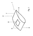
- Fig. 1 shows a prepared for carrying out the method according to the invention portion of a rotor blade 1.
- the to a rotor blade section 2 in Fig. 1 belonging rotor blade 1 is part of a (not shown) wind turbine. It is common in wind turbines to provide the rotor blade 1 with vortex generators 3 to increase the buoyancy of the rotor blade 1.
- vortex generators 3 according to FIGS. 2a . 2 B and Fig. 3
- these are wings which are triangular in cross section and protrude perpendicularly from a suction side 4 of a rotor blade outer skin 6.
- the triangular-shaped wing is perpendicular to a rotor blade trailing edge 7 at right angles with a vertically sloping side of the triangle 31 and a rotor blade nose 8 toward acute sloping flat.
- Vortex generators 3 can be oblique, like Fig. 3 shows, or be arranged exactly parallel to an air flow direction S on the rotor blade outer skin 6. As the rotor blade 1 flows around, each vortex generator 3 generates downstream a vortex which releases downstream from the vertical edge 31 of the vortex generator 3. The vortex avoids the formation of an excessive and too thick turbulent boundary layer between the rotor blade outer skin 6 of the rotor blade 1 and the laminar air flow S flowing around the rotor blade 1. This prevents a tearing off of the laminar flow from the rotor blade 1, and higher and stronger forces can occur Buoyancy forces act on the rotor blade 1 and form.
- Vortex generators 3 are often in a base plate 33 according to FIGS. 2a and 2 B integrated. In the arrangement of vortex generator 3 and base plate 33 is according to FIGS. 2a and 2 B to an integrated component, which is made in one piece, for example, in an injection molding of a plastic.
- the base plate 33 in the FIGS. 2a and 2 B is placed on a corresponding adhesive surface 9, which in Fig. 1 spaced from the rotor blade nose 8 is provided, glued. The sticking is done in the method according to the invention.
- the corresponding adhesive surface 9 of the rotor blade outer skin 6 is first prepared.
- the corresponding adhesive surface 9 is brought into a rough and clean state.
- the corresponding adhesive surface 9 can either be sandblasted or abraded beforehand with sand.
- the rotor blade 1 is already manufactured during its manufacture with a protective foil surrounding the rotor blade outer skin 6, in particular in the region of the corresponding adhesive surface 9.
- the protective film is introduced as a first layer into a manufacturing mold of a rotor blade half shell, and subsequently the laminate structure is introduced over the protective film into the rotor blade half shell.
- the finished rotor blade half shell is taken from the manufacturing mold, and the protective film represents the outermost skin of the rotor blade outer skin 6.
- the protective film can be removed from the laminate composite of the rotor blade 1 and leaves the rough and clean corresponding adhesive surface 9.
- the protective film must be removed directly before gluing the base plate 33 of the vortex generator 3.
- no subsequent treatment of the corresponding adhesive surface 9 may take place, for example, by sand or other impurities. Between the removal of the protective film and the gluing of the base plate 33 on the corresponding adhesive surface 9 may not be more than half an hour, since otherwise the freed from the protective film corresponding adhesive surface 9 is already contaminated with dust particles that are present in the ambient air.
- the corresponding adhesive surface 9 is treated with sand prior to the actual adhering of the base plate 33.
- the corresponding adhesive surface 9 is sandblasted with a grit of 80 to 200 grit. After the sand treatment, the corresponding adhesive surface 9 is cleaned of dust and other impurities.
- the corresponding adhesive surface 9 is cleaned, for example, with VHB® surface cleaner from 3M. VHB® surface cleaner is generally available for purchase under this name.
- the isopropyl alcohol may be mixed with water, the isopropyl alcohol accepting less than 50% by volume of the mixture.
- the base plate 33 After cleaning, the base plate 33 should be glued at most within half an hour.
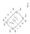
- FIGS. 2a and 2 B the conventional base plate 33 with two vortex generators 3 processed for the method according to the invention is glued on the upper side of the base plate 33 at the four corners, in each case a portion of a protective band 33a, 33b, 33c, 33b and centrally a portion of a protective band 34. which are withdrawn after completion of the attachment process.
- the sections of the protective tapes 33a, 33b, 33c, 33b, 34 can each be a section of a single-sided adhesive tape. He does not remain at the top of the base plate 33rd
- a hole is bored through the five sections of the protective tapes 33a, 33b, 33c, 33d, 34 and through the base plate 33 at the four corners and centrally.
- the hole is preferably circular and penetrates the base plate 33 completely.
- other hole cross sections are conceivable.
- inlet opening 34 ' has a diameter of 5.5 mm and has an equal distance to each of the four corners, while four outlet openings 33'a, 33'b, 33'c, 33'd, which are bored through the four portions of the protective tapes 33a, 33b, 33c, 33d and the corners of the base plate 33, each have an inner diameter of 2.5 mm.
- Fig. 2b shows the base plate 33 with the two vortex generators 3 in a view from below.
- These five openings 33'a, 33'b, 33'c, 33'd, 34 ' are here designed as circular cross-section bores.
- the base plate 33 is attached to its in Fig. 2b illustrated bottom, which acts as an adhesive surface 36, circumferentially taped along its outer edge with a double-sided adhesive tape 37.
- a double-sided adhesive tape 37 When gluing the double-sided adhesive tape 37 onto the edge of the adhesive surface 36, make sure that the circumferential double-sided adhesive tape 37 rotates the base plate 33 levelly and without step formation, since the adhesive surface 36 for provisionally fixing the base plate 33 on the corresponding adhesive surface 9 of the rotor blade outer skin 6 is glued by means of the circumferential double-sided adhesive tape 37 and the double-sided adhesive tape 37 acts as a seal in the further course of the process.
- the provisional adhesive bond between the base plate 33 and the rotor blade outer skin 6 must be adhesive-tight in some processes, but air-tight in other processes, so that the double-sided adhesive tape 37 is adhered carefully and without gaps or overlaps circumferentially along the edge of the underside of the base plate 33.
- the distance of the outlet openings 33'a, 33'b, 33'c, 33'd from the double-sided adhesive tape 37 should be at most 5 mm.
- a SAFT® 3230 (VHB 4991) acrylic foam adhesive tape from 3M with a thickness of 2.3 mm and a width of 10 mm can be used.
- the underside of the base plate 33 was also cleaned with 3M VHB® surface cleaner or isopropyl alcohol, also here for safety reasons, the isopropyl alcohol is diluted with water, the isopropyl alcohol makes up less than 50 vol.% Of the mixture.
- the adhesive surface 36 is cleaned with a dry, clean cloth to remove cleaning residues.
- neither the adhesive surface 36 of the base plate 33 nor the corresponding adhesive surface 9 of the rotor blade outer skin 6 may be touched without gloves.
- the adhesive surface 36 and the corresponding adhesive surface 9 are the same size and have a same circumferential outer shape. They fit together form-fitting.
- the Fig. 3 shows the already glued to the rotor blade outer skin 6 base plate 33. After sticking the base plate 33, the two vortex generators 3 are perpendicular from the rotor blade outer skin 6 to, as described above, respectively to generate the buoyancy increasing air vortex.
- FIGS. 4 and 5 show an inventive Anpresswerkmaschine 40, with the base plate 33 according to the invention with its adhesive surface 36 on the corresponding adhesive surface 9 of the rotor blade outer skin 6 safely and firmly sticking.
- the pressing tool 40 is in Fig. 4 represented over the base plate 33 with the vortex generators 3 across.
- the pressing tool 40 has two suction pads 41, from each of which a vacuum hose 42 goes off, which generates a negative pressure on the rotor blade side of the suction pads 41, thereby sucking the suction pads 41 safely and slip-resistant on the rotor blade outer skin 6.
- a vacuum hose 42 goes off, which generates a negative pressure on the rotor blade side of the suction pads 41, thereby sucking the suction pads 41 safely and slip-resistant on the rotor blade outer skin 6.
- the suction pads 41 immediately lose their suction power, and the pressing tool 40 can easily be removed again from the rotor blade outer skin 6 after the end of the process.
- the pressing tool 40 further has a Anpresskuppel 44.
- the Anpresskuppel 44 has in this embodiment, an inner height which is greater than the highest height of the recorded vortex generators 3 on the outside of the base plate 33.
- a peripheral edge of the Anpresskuppel 44 which serves as a circumferential contact surface 46, dimensions that the dimensions of the circumference of the base plate 33 are adjusted.
- a width spacing of opposite portions of the circumferential contact surface 46 is formed about 1 cm smaller than the width of the base plate 33, while a longitudinal distance between opposing portions of the circumferential contact surface 46 also slightly lower, d. H. 1 cm less than the length of the base plate 33 is formed.
- the Anpresskuppel 44 is connected to two transverse rods 50 height adjustable relative to them by means of a height adjustment device 47.
- the two transverse rods 50 are connected by vertical rods 51 with the two suction pads 41.
- From each of the cross bars 50 is a respective grab bar 52, with which the entire Anpresstechnikmaschine 40 can be brought.
- the height adjustment device 47 between Anpresskuppel 44 and cross bar 50 makes it possible to change the distance of the Anpresskuppel 44 to the rotor blade outer skin 6 and thus to change a contact pressure of the Anpresstechnikmaschines 40 against the base plate 33.
- the base plate 33 is according to Fig. 4 not positively on the rotor blade outer skin 6, but it is, as in the Fig. 2b shown by means of the circumferential double-sided adhesive tape 37 along the entire adhesive surface 36 by a gap 53 spaced from the rotor blade outer skin 6 is arranged.
- the adhesive surface 36 and the corresponding adhesive surface 9 have over their entire extent a substantially equal distance from each other, which corresponds to a height of the gap 53.
- the Anpresskuppel 44 has four depressions 60a, 60b, 60c, 60d at its four rounded corners and a central lowering 61.
- the reductions 60a, 60b, 60c, 60d, 61 are open to the base plate 33 and enter with proper adjustment of the Anpresskuppel 44th above the Base plate 33 the view and the passage on the inlet port 34 'and the four outlet ports 33'a, 33'b, 33'c, 33'd free, ie, the inlet opening 34' can be operated by the central sink 61 in the Anpresskuppel 44 ,
- Fig. 4 shows an injection tube 70 with an injection nose 71, which is inserted into the inlet opening 34 '.
- the injection tube 70 can be inserted into the inlet opening 34 'through the central depression 61 of the pressure-applying dome 44.
- the injection tube 70 has at its end opposite the injection nose 71 a pump 72, with the liquid adhesive 80 can be pressed through the injection tube 70 and the injection nose 71 in the gap 53 and is also pressed. As much liquid adhesive 80 is pressed into the gap 53 until at least some adhesive 80 swells out of all four outlet openings 33'a, 33'b, 33'c, 33'd.
- outlet openings 33'a, 33'b, 33'c, 33'd are also visible via the four depressions 60a, 60b, 60c, 60d of the pressure dome 44, so that it can be visually recognized when the gap 53 is completely filled with adhesive 80 is filled.
- the adhesive 80 is not pressed in by means of the pump 72, but in each case a vacuum hose is connected to the four outlet openings 33'a, 33'b, 33'c, 33'd, and A negative pressure is generated by a vacuum pump in the gap 53.
- a vacuum hose is connected to the four outlet openings 33'a, 33'b, 33'c, 33'd, and A negative pressure is generated by a vacuum pump in the gap 53.
- liquid adhesive 80 is sucked homogeneously into the gap 53 by the vacuum and is distributed there.
- the vacuum device for generating the vacuum in the gap 53 and the vacuum device for generating the negative pressure of the suction pads 41 are decoupled from each other.
- Fig. 5 shows the pressing tool 40 of Fig. 4 in a top view.
- the same reference numerals here mean the same components as in Fig. 4 ,
- the two horizontally extending transverse rods 50 at one end of which one of the two suction pads 41 and at the other end of which the other of the two suction pads 41 are arranged above the vertical rods 51. From each of the two suction pads 41, the vacuum hose 42 goes off.
- the two transverse rods 50 are provided with the two handles 52, which make it possible, the entire Anpresswerkmaschine 40 of Fig. 5 to grab and raise and spend.
- the central depression 61 points towards the inlet opening 34 'and the four depressions 60a, 60b, 60c, 60d at the rounded corners of the pressure dome 44 towards the four outlet openings 33'a, 33'b, 33'c, 33'd.
- the respective outlet openings 33'a, 33'b, 33'c, 33'd of the base plate 33 are visible when the pressing tool 40 is adjusted and placed on the base plate 33.
- the pressing tool 40 makes it possible according to the invention, the base plate 33 firmly on the To press corresponding adhesive surface 9 and also to distribute the liquid adhesive 80 in a very homogeneous manner, without inclusion of air bubbles, in the gap 53 between the adhesive surface 36 and corresponding adhesive surface 9, so as to produce a particularly strong and durable adhesive bond.
Landscapes
- Engineering & Computer Science (AREA)
- Mechanical Engineering (AREA)
- General Engineering & Computer Science (AREA)
- Sustainable Development (AREA)
- Fluid Mechanics (AREA)
- Life Sciences & Earth Sciences (AREA)
- Physics & Mathematics (AREA)
- Sustainable Energy (AREA)
- Chemical & Material Sciences (AREA)
- Combustion & Propulsion (AREA)
- Wind Motors (AREA)
- Lining Or Joining Of Plastics Or The Like (AREA)
- Adhesives Or Adhesive Processes (AREA)
- Structures Of Non-Positive Displacement Pumps (AREA)
Abstract
Description
- Die Erfindung betrifft ein Verfahren zur Befestigung eines Anbauteils an einer Klebefläche eines Bauteils, insbesondere eines Rotorblattes. Die Erfindung betrifft auch eine Montagevorrichtung zur Durchführung des erfindungsgemäßen Verfahrens.
- Verfahren zur Befestigung von Anbauteilen an einem Bauteil sind im Stand der Technik natürlich hinlänglich bekannt. Insbesondere ist es auch bekannt, Vortexgeneratoren an Bauteile einer Windenergieanlage, insbesondere an einem Rotorblatt zu befestigen.
- Auf ein Rotorblatt müssen, je nach Typ des Rotorblattes, unterschiedliche Anbauteile noch während des Herstellungsverfahrens oder auch auf der Baustelle angebracht werden. Bei diesen Anbauteilen handelt es sich beispielsweise um Regenabweiser, Vortexgeneratoren oder sogenannte Stall-Strips. Sogenannte Stall-Strips werden an der Rotorblattnase angebracht. Sie bewirken ein früheres Einsetzen der Strömungsablösung des um das Rotorblatt strömenden Luftstromes. Dadurch kann die maximale Leistungsaufnahme der Windenergieanlage begrenzt werden.
- Bei Vortexgeneratoren hingegen handelt es sich in der Regel um im Querschnitt dreieckförmige Flügel, die von einer Saugseite der Rotorblattaußenhaut im Wesentlichen senkrecht abstehen. Das Dreieck ist zur Rotorblatthinterkante hin rechtwinkelig mit einer senkrecht abfallenden Dreieckseite und zur Rotorblattnase hin spitzwinkelig abfallend ausgebildet. Vortexgeneratoren können zueinander schräg oder exakt parallel zueinander zur Luftstromrichtung auf der Rotorblattaußenhaut angeordnet sein. Bei Umströmung des Rotorblattes erzeugt jeder Vortexgenerator stromabwärts einen Wirbel, der sich stromabwärts von der senkrechten Kante des Vortexgenerators löst. Diese Wirbel oder auch Vortices genannt, verhindern das Ausbilden einer zu starken und zu dicken turbulenten Grenzschicht zwischen der Außenhaut des Rotorblattes und der das Rotorblatt umströmenden laminaren Luftströmung. Dadurch wird einem Abreißen oder Ablösen der laminaren Strömung vom Rotorblatt entgegengewirkt, und es können höhere und stärkere Auftriebskräfte am Rotorblatt wirken und sich ausbilden.
- Welches Anbauteil auch immer an das Rotorblatt angebracht werden muss, ist es in der Regel immer von Wichtigkeit, dass die Montage möglichst schnell und zuverlässig erfolgt und dass das Anbauteil dauerhaft mit dem Rotorblatt verklebt wird.
- Gemäß dem Stand der Technik werden die Anbauteile mit verschiedenen Verklebungen oder Verschraubungen oder auch Nieten am Rotorblatt befestigt. Zur Herstellung der Klebverbindung werden die beiden Klebeflächen des Anbauteils und des Rotorblattes vorab mit dem Kleber bestrichen und das Anbauteil wird so lange am Rotorblatt fixiert gehalten, bis der Kleber ausgehärtet ist oder zumindest genügend Festigkeit besitzt, damit das Bauteil nicht mehr verrutschen und/oder abfallen kann. Zur Herstellung der Klebverbindung werden insbesondere Epoxidharzkleber, PU-Kleber, das sind Klebstoffe, die auf Polyurethan basieren, MA-Kleber, das sind Kleber, die auf Methacrylat basieren, verwendet.
- Es hat sich gezeigt, dass die genannten Verbindungen nicht dauerhaft sind. Die Anbauteile müssen von Zeit zu Zeit vollständig abgelöst und neu angeklebt werden. Zur Verlängerung der Standzeiten ist es zwar möglich, Kleber mit langen Fixier- und Aushärtezeiten zu verwenden, dieses hat jedoch den erheblichen Nachteil, dass die Anbauteile während des Klebevorganges lange fixiert gehalten werden müssen. Es hat sich auch gezeigt, dass es in der Praxis schwierig ist, zwei Klebeflächen homogen mit Klebstoff zu bestreichen, da das Auftreten von Lufteinschlüssen, Luftblasen u. Ä. in erheblichem Maße auftritt.
- Es ist daher Aufgabe der vorliegenden Erfindung, ein eingangs genanntes Verfahren zur Befestigung eines Anbauteils an einem Bauteil zur Verfügung zu stellen, das eine dauerhafte Klebverbindung hervorbringt und bei dem der Monteur das Anbauteil dennoch nicht lange fixiert halten muss. Es ist auch Aufgabe der vorliegenden Erfindung, eine Montagevorrichtung zur Verfügung zu stellen, die die Durchführung eines derartigen Verfahrens ermöglicht.
- Die Aufgabe wird in ihrem ersten Aspekt durch ein Verfahren mit den Merkmalen des Anspruchs 1 gelöst.
- Das erfindungsgemäße Verfahren eignet sich insbesondere zur Befestigung eines Anbauteils an einem Bauteil, insbesondere an einem Rotorblatt. Es ist jedoch nicht auf Rotorblätter beschränkt, sondern eignet sich auch zur Befestigung von Anbauteilen auch an anderen Einrichtungen einer Windenergieanlage. Es ist sogar denkbar, das erfindungsgemäße Verfahren beispielsweise zum Anbringen von Anbauteilen an Motorradhelmen zu verwenden. Das erfindungsgemäße Verfahren eignet sich insbesondere dazu, Anbauteile an Laminatverbunde anzukleben, wobei das Anbauteil selbst günstigerweise ebenfalls ein Laminat oder Laminatverbund ist.
- Erfindungsgemäß werden das Bauteil mit einer Klebefläche und das Anbauteil mit einer korrespondierenden Klebefläche versehen. Das Befestigungsverfahren ist im Kern ein Klebverfahren. Zur Befestigung werden die Klebefläche und die korrespondierende Klebefläche aneinandergesetzt, ohne sich jedoch dabei vollflächig zu berühren. Erfindungsgemäß ist ein Spalt zwischen der Klebefläche und der korrespondierenden Klebefläche ausgebildet, der die größte Fläche der Klebefläche ausmacht. Das Anbauteil wird mit seiner Klebefläche gegen die korrespondierende Klebefläche gepresst, um zumindest eine Zeitlang eine fixierte Position beizubehalten. Gleichzeitig wird Klebstoff in den Spalt injiziert. Das Anbauteil wird so lange gegen das Bauteil gepresst, bis der Klebstoff vollständig abgebunden ist oder zumindest soweit abgebunden ist, bis das Anbauteil mit dem Bauteil eine feste Klebverbindung ausbildet. Zum Anpressen kann ein Klebeband verwendet werden.
- Zur Durchführung des erfindungsgemäßen Verfahrens wird das Anbauteil mit Öffnungen versehen, die eine klebstoffleitende Verbindung zu der korrespondierenden Klebefläche aufweisen. Erfindungsgemäß wird der vorzugsweise flüssige Klebstoff durch die Öffnungen des Anbauteils zu dessen korrespondierender Klebefläche geleitet. Von dort gelangt der flüssige Klebstoff in den Spalt und füllt den Spalt zwischen Klebefläche und korrespondierender Klebefläche vollständig und vorzugsweise luft- und blasenfrei aus. Wenn der Spalt vollständig luft- und blasenfrei mit Klebstoff ausgefüllt ist, wird die Zufuhr von Klebstoff gestoppt, und der Klebstoff beginnt auszuhärten und eine feste Klebverbindung zwischen Anbauteil und Bauteil herzustellen.
- In einer bevorzugten Variante des erfindungsgemäßen Verfahrens ist der Spalt zwischen der Klebefläche und der korrespondierenden Klebefläche umlaufend klebstoffdicht abgeschlossen. Der Spalt erstreckt sich günstigerweise beinahe über die gesamte Ausdehnung der Klebefläche und der mit ihr korrespondierenden Klebefläche. Günstigerweise ist an den Rändern der Klebefläche eine Dichtung vorgesehen, die den Spalt günstigerweise klebstoffdicht, vorzugsweise luftdicht gegen die Umgebung abdichtet. Dadurch wird der in den Spalt geleitete flüssige Klebstoff am Austreten aus dem Spalt gehindert.
- Bei dieser Variante des Verfahrens ist die korrespondierende Klebefläche günstigerweise umlaufend mit einem doppelseitigen Haftklebeband beklebt, und die mit dem doppelseitigen Klebeband versehene Klebefläche des Anbauteils wird auf die korrespondierende Klebefläche angesetzt, und es bildet sich durch die Haftklebeverbindung des doppelseitigen Haftklebebandes zwischen Klebefläche und korrespondierender Klebefläche die klebstoffdichte Dichtung aus, die den Spalt umlaufend abdichtet. Beim Aufbringen des doppelseitigen Haftklebebandes auf das Anbauteil ist darauf zu achten, dass Abschnitte des Klebebandes, die von einer Rolle abgeschnitten werden, ohne Überlappungen oder Stufen, sondern aneinander auf Stoß geklebt werden, um einen die gesamte korrespondierende Klebefläche in gleicher Höhe und ohne Lücken umlaufenden Haftklebebandstreifen auszubilden. Nach dem Aufbringen des Haftklebebandes auf die korrespondierende Klebefläche entlang deren gesamten Umfanges wird eine Schutzfolie der freien Seite des Haftklebebandes abgezogen, und das Anbauteil wird exakt positioniert gegen die Klebefläche des Bauteils gedrückt.
- Das Haftklebeband hat zum einen die Funktion, dass es das Anbauteil zumindest kurzzeitig an dem Bauteil fixiert, um den eigentlichen Klebvorgang durch Injektion des flüssigen Klebstoffes bei einer stabilisierten relativen Anordnung zu ermöglichen, zum anderen erzeugt das umlaufende Haftklebeband einen klebstoffdichten Abschluss, der den Spalt nach außen abdichtet und einem Austritt von Klebstoff aus dem Spalt heraus entgegenwirkt.
- Erfindungsgemäß werden in das Anbauteil Öffnungen eingebracht, soweit nicht bereits während des Herstellungsverfahrens des Anbauteils Öffnungen in dem Anbauteil vorgesehen werden.
- Vorzugsweise werden die der korrespondierenden Klebefläche gegenüberliegenden Bereiche einer Außenwandung des Anbauteils mit einem Schutzband abgedeckt, und die Öffnungen werden durch das jeweilige Schutzband hindurch in das Anbauteil eingebracht. Dabei wird das Schutzband vorzugsweise nur über Austrittsöffnungen angeordnet; Eintrittsöffnungen können, müssen aber nicht mit dem Schutzband abgedeckt werden.
- Günstigerweise verhindern die Schutzbänder einen direkten Kontakt der Außenwandung des Anbauteils mit überschüssigem, in den Spalt eingebrachtem und aus den Austrittsöffnungen und ggf. auch der Eintrittsöffnung heraustretendem Klebstoff. Die Schutzbänder können nach dem Eindringen des Klebstoffs in den Spalt und dessen geringfügigem Austreten aus den Austrittsöffnungen wieder von der Außenwand abgezogen werden und hinterlassen eine klebstofffreie Außenwandung des Anbauteils.
- Zur Herstellung einer festen Klebverbindung zwischen Anbauteil und Bauteil ist es notwendig, dass das Anbauteil nicht nur fixiert an dem Bauteil gehalten wird, sondern auch angepresst wird. Erfindungsgemäß wird ein Anpresswerkzeug vorübergehend an oder über dem Anbauteil angeordnet, das sich an einer Außenwandung der Einrichtung ansaugt und das Anbauteil an die Außenwandung des Bauteils drückt. Bei dem Bauteil kann es sich um eine Windenergieanlage, insbesondere um ein Rotorblatt handeln.
- Um den Anpressvorgang des Anbauteils an das Bauteil zu ermöglichen, berührt das Anpresswerkzeug das Anbauteil vorzugsweise an dessen umlaufendem Rand und drückt den umlaufenden Rand an die korrespondierende Klebefläche der Einrichtung, insbesondere des Rotorblattes. Das Anbauteil ist in der Regel elastisch. Dennoch ist es hinreichend, zur Erzeugung eines genügend großen Anpressdruckes des Anbauteils an die Einrichtung, das Anbauteil an einem umlaufenden Rand anzudrücken. Durch den Anpressdruck entlang des umlaufenden Randes kann der Rand auf der Einrichtung nicht verrutschen, und das Anbauteil behält seine Ursprungsform während des Verfahrens im Wesentlichen oder vollständig bei.
- Günstigerweise wird Klebstoff durch wenigstens eine der Öffnungen in den Spalt eingepresst. Dazu ist eine Injektionsvorrichtung vorgesehen, die mit der wenigstens einen Einlassöffnung in Verbindung steht und flüssigen Klebstoff unter Druck durch die wenigstens eine Einlassöffnung in den Spalt einpresst. Es können genau eine oder zwei oder auch jede höhere Anzahl an Einlassöffnungen vorliegen. Der Druck kann mittels einer Klebstoffpumpe, beispielsweise in Form eines verfahrbaren Kolbens, aufgebaut werden. Der unter Druck durch die wenigstens eine Einlassöffnung eingebrachte Klebstoff verteilt sich im Spalt zwischen Klebefläche und korrespondierender Klebefläche und tritt aus der wenigstens einen Auslassöffnung wieder aus dem Spalt aus. Es wird so lange Klebstoff in den Spalt eingepresst, bis aus allen Austrittsöffnungen zumindest etwas Klebstoff ausgetreten ist, wodurch visuell kontrolliert werden kann, dass der gesamte Spalt mit Klebstoff gefüllt ist. Dadurch wird eine vollflächige Klebverbindung ohne Lufteinschluss zwischen Anbauteil und Einrichtung ermöglicht. Dies erspart aufwendige Prüfverfahren.
- In einer anderen Variante des Injektionsverfahrens für den Klebstoff wird durch wenigstens eine der Öffnungen ein Unterdruck in dem Spalt erzeugt und durch wenigstens eine andere Öffnung Klebstoff in den Spalt injiziert. Dabei wird also kein Druck bei der Klebstoffzufuhr aufgebaut, sondern der Klebstoff wird quasi durch Unterdruck im Spalt aus einem Klebstoffreservoir eingesaugt und verteilt sich auch so vollständig im Spalt. Zur Durchführung dieses Verfahrens muss die umlaufende Abdichtung des Spaltes nicht nur klebstoffdicht, sondern auch luftdicht ausgebildet sein.
- Vorzugsweise werden die Klebefläche und besonders bevorzugt auch die korrespondierende Klebefläche als Bereiche des Bauteils bzw. des Anbauteils vor dem Aufbringen des Klebstoffes an dem Bauteil bzw. dem Anbauteil vorbereitet oder präpariert. Insbesondere werden die Bereiche zur Klebfläche bzw. korrespondierenden Klebefläche aufgeraut, um eine möglichst feste Klebverbindung zwischen dem Klebstoff und der jeweiligen Klebefläche herzustellen. Vorzugsweise werden die Klebefläche und die korrespondierende Klebefläche vor dem Aufbringen des Klebstoffes auch gereinigt.
- In ihrem zweiten Aspekt wird die Aufgabe durch eine Montagevorrichtung mit den Merkmalen des Anspruchs 13 erfüllt.
- Die erfindungsgemäße Montagevorrichtung umfasst ein Anpresswerkzeug und eine Injektionseinrichtung.
- Das Anpresswerkzeug ist zum Anpressen eines Anbauteils mit einer Klebefläche an eine korrespondiere Klebefläche eines Bauteils, insbesondere eines Rotorblattes, bestimmt. Das Anpresswerkzeug umfasst wenigstens eine Ansaugeinrichtung, mit der das Anpresswerkzeug an einer Wandung des Bauteils vorübergehend ansaugbar ist, sowie eine Anpresseinrichtung, mit der das Anbauteil abgedichtet, unter Ausbildung eines Spaltes zwischen der Klebefläche und der korrespondierenden Klebefläche an die korrespondierende Klebefläche angepresst und dadurch gleichzeitig abgedichtet wird. Das Anpresswerkzeug verhindert ein Aufblähen des Bauteils durch den eingepressten Klebstoff, und es hält das Anbauteil in seiner Ursprungsform.
- Die Montagevorrichtung weist in einer Ausführungsform auch die Injektionseinrichtung für Klebstoff in den Spalt zwischen der Klebefläche und der korrespondierenden Klebefläche auf.
- Die gesamte Montagevorrichtung ist zur Durchführung eines der eingangs genannten erfindungsgemäßen Verfahren bestimmt, aber sie ist nicht zum Verbleib am Bauteil bestimmt. Sie wird nach der Durchführung des Klebeverfahrens wieder vom Bauteil abgenommen und hinterlässt ein fest am Bauteil angeklebtes Anbauteil.
- Günstigerweise ist die Ansaugeinrichtung als wenigstens ein Saugpad ausgebildet. Bei einem Saugpad handelt es sich um eine ebene, flächig ausgebildete Ansaugfläche, die günstigerweise mit einer Vakuumleitung, vorzugsweise einer Unterdruckleitung in Verbindung steht. Beim Aufsetzen des Saugpads auf eine möglichst ebene und glatte Außenwandung des Bauteils wie die Rotorblattaußenhaut wird über die Vakuumleitung ein Unterdruck auf der rotorblattseitigen Auflagefläche des Saugpads erzeugt und das Saugpad durch den sich ausbildenden Unterdruck an die Außenwandung gesaugt.
- Vorzugsweise weist das Anpresswerkzeug der Montagevorrichtung zwei oder mehr Saugpads auf, um eine zumindest vorübergehende rutschfeste Verbindung zwischen Montagewerkzeug und Bauteil herzustellen, damit das Anbauteil durch das Anpresswerkzeug der Montagevorrichtung fest und fixiert gegen das Bauteil gedrückt werden kann.
- Von dem Saugpad geht günstigerweise ein Gestänge ab, und an der Saugpadseite des Gestänges ist die Anpresseinrichtung für das Anbauteil vorgesehen.
- Vorzugsweise weist die Anpresseinrichtung eine Anpresskuppel mit einer umlaufenden Anpressfläche auf. Dadurch ist es möglich, dass das Anbauteil, bei dem es sich vorzugsweise um die Grundplatte eines Vortexgenerators handelt, entlang seines Umfangs gegen die Außenwandung, vorzugsweise Rotorblattaußenhaut gedrückt wird.
- Vorzugsweise weist die Anpresskuppel wenigstens eine Absenkung bis auf Höhe der Anpressfläche der Anpresskuppel auf, die eine Betätigung durch die Absenkung hindurch an dem angedrückten Anbauteil ermöglicht. Bei der Betätigung kann es sich beispielsweise um das Anbringen einer Injektionsnase eines Injektionsschlauches an die wenigstens eine Einlassöffnung des Anbauteils handeln oder auch um das Anbringen von Vakuumleitungen an alle Auslassöffnungen des Anbauteils, um einen Unterdruck im Spalt zwischen korrespondierender Klebefläche und Klebefläche zu erzeugen.
- In einer bevorzugten Ausführungsform der erfindungsgemäßen Montagevorrichtung ist die Anpresseinrichtung höhenverstellbar parallel zum Saugpad ausgebildet. Dadurch ist eine nachträgliche Justierung des Anpressdruckes des Anbauteils an dem Bauteil möglich.
- Die Montagevorrichtung weist günstigerweise eine Injektionseinrichtung mit einer Injektionsnase zum Anschluss für wenigstens eine Einlassöffnung des Anbauteils auf. Die Injektionsnase wird vom Monteur günstigerweise durch eine Absenkung der Anpresskuppel an die wenigstens eine Einlassöffnung angeschlossen. Dazu weist die wenigstens eine Einlassöffnung einen mit der Injektionsnase korrespondierenden Anschluss auf, der eine klebstoffdichte Verbindung ermöglicht.
- In einer weiteren günstigen Ausführungsform der Erfindung weist die Injektionseinrichtung eine Vakuumpumpe auf, die an die wenigstens eine, vorzugsweise alle Auslassöffnungen am Bauteil anschließbar ist und die einen Unterdruck im Spalt erzeugt.
- Die Erfindung wird anhand eines Ausführungsbeispiels in sechs Figuren beschrieben. Dabei zeigen:
- Fig. 1
- eine perspektivische Ansicht eines Abschnitts eines Rotorblattes mit einer korrespondierenden Klebefläche,
- Fig. 2a
- eine zur Anwendung in einem erfindungsgemäßen Befestigungsverfahren präparierte Grundplatte mit zwei Vortextgeneratoren in einer Draufsicht,
- Fig. 2b
- die Grundplatte in
Fig. 2a in einer Untenansicht, - Fig. 3
- eine Ansicht des Rotorblattes in
Fig. 1 mit angeklebter Grundplatte mit Vortexgeneratoren, - Fig. 4
- eine seitliche Ansicht einer erfindungsgemäßen Montagevorrichtung mit einem Anpresswerkzeug über einer Grundplatte mit Vortexgenerator und Injektionseinrichtung,
- Fig. 5
- eine Draufsicht des Anpresswerkzeugs in
Fig. 4 . -
Fig. 1 zeigt einen zur Durchführung des erfindungsgemäßen Verfahrens vorbereiteten Abschnitt eines Rotorblattes 1. Das zu einem Rotorblattabschnitt 2 inFig. 1 gehörende Rotorblatt 1 ist Teil einer (nicht dargestellten) Windenergieanlage. Es ist bei Windenergieanlagen üblich, zur Erhöhung des Auftriebs des Rotorblattes 1 das Rotorblatt 1 mit Vortexgeneratoren 3 zu versehen. Bei Vortexgeneratoren 3 gemäßFign. 2a ,2b undFig. 3 handelt es sich in der Regel um im Querschnitt dreieckförmige Flügel, die von einer Saugseite 4 einer Rotorblattaußenhaut 6 senkrecht abstehen. Der dreieckförmige Flügel ist zu einer Rotorblatthinterkante 7 hin rechtwinkelig mit einer senkrecht abfallenden Dreieckseite 31 und zu einer Rotorblattnase 8 hin spitzwinkelig flach abfallend ausgebildet. Vortexgeneratoren 3 können schräg, wieFig. 3 zeigt, oder exakt parallel zu einer Luftstromrichtung S auf der Rotorblattaußenhaut 6 angeordnet sein. Bei Umströmung des Rotorblattes 1 erzeugt jeder Vortexgenerator 3 stromabwärts einen Wirbel, der sich stromabwärts von der senkrechten Kante 31 des Vortexgenerators 3 löst. Der Wirbel oder Vortex verhindert das Ausbilden einer zu starken und zu dicken turbulenten Grenzschicht zwischen der Rotorblattaußenhaut 6 des Rotorblattes 1 und der das Rotorblatt 1 umströmenden laminaren Luftströmung S. Dadurch wird einem Abreißen der laminaren Strömung vom Rotorblatt 1 entgegengewirkt, und es können höhere und stärkere Auftriebskräfte am Rotorblatt 1 wirken und sich ausbilden. - Vortexgeneratoren 3 sind häufig in eine Grundplatte 33 gemäß
Fign. 2a und2b integriert. Bei der Anordnung aus Vortexgenerator 3 und Grundplatte 33 handelt es sich gemäßFign. 2a und2b um ein integriertes Bauteil, das beispielsweise in einem Spritzgussverfahren aus einem Kunststoff einteilig hergestellt ist. - Die Grundplatte 33 in den
Fign. 2a und2b wird auf eine korrespondierende Klebefläche 9, die inFig. 1 beabstandet von der Rotorblattnase 8 vorgesehen ist, aufgeklebt. Das Aufkleben geschieht in dem erfindungsgemäßen Verfahren. - In einem ersten Schritt des Verfahrens wird zunächst die korrespondierende Klebefläche 9 der Rotorblattaußenhaut 6 präpariert.
- Die korrespondierende Klebefläche 9 wird in einen rauen und sauberen Zustand gebracht. Zur Erzeugung einer hinreichenden Rauigkeit kann die korrespondierende Klebefläche 9 vorab mit Sand entweder abgestrahlt oder abgerieben werden. In einer anderen Variante des Verfahrens wird das Rotorblatt 1 während seiner Herstellung bereits mit einer die Rotorblattaußenhaut 6, insbesondere im Bereich der korrespondierenden Klebefläche 9, umgebenden Schutzfolie gefertigt. Die Schutzfolie wird als erste Lage in eine Fertigungsform einer Rotorblatthalbschale eingebracht, und nachfolgend wird der Laminataufbau über der Schutzfolie in die Rotorblatthalbschale eingebracht. Die fertige Rotorblatthalbschale wird der Fertigungsform entnommen, und die Schutzfolie stellt die äußerste Haut der Rotorblattaußenhaut 6 dar.
- Nach Zusammenkleben beider Rotorblatthalbschalen und Fertigstellen des gesamten Rotorblattes 1 kann die Schutzfolie von dem Laminatverbund des Rotorblattes 1 abgezogen werden und hinterlässt die raue und saubere korrespondierende Klebefläche 9. Die Schutzfolie muss dazu direkt vor dem Aufkleben der Grundplatte 33 des Vortexgenerators 3 entfernt werden. Nach dem Entfernen der Schutzfolie darf keine nachträgliche Behandlung der korrespondierenden Klebefläche 9 beispielsweise durch Sand oder andere Verunreinigungen stattfinden. Zwischen der Entfernung der Schutzfolie und dem Aufkleben der Grundplatte 33 auf die korrespondierende Klebefläche 9 darf nicht mehr als eine halbe Stunde liegen, da anderenfalls die von der Schutzfolie befreite korrespondierende Klebefläche 9 bereits mit Staubpartikeln, die in der Umgebungsluft vorhanden sind, kontaminiert ist.
- Wenn die korrespondierende Klebefläche 9 nicht mit einer Schutzfolie versehen oder die Schutzfolie vor längerer Zeit entfernt wurde, wird die korrespondierende Klebefläche 9 vor dem eigentlichen Aufkleben der Grundplatte 33 mit Sand behandelt. Dazu wird die korrespondierende Klebefläche 9 mit Sand mit einer Körnung von 80 bis 200 Grit abgestrahlt. Nach der Sandbehandlung wird die korrespondierende Klebefläche 9 von Staub und anderen Verunreinigungen gesäubert. Die korrespondierende Klebefläche 9 wird beispielsweise mit VHB® Oberflächenreiniger der Firma 3M gereinigt. VHB®-Oberflächenreiniger ist unter dieser Bezeichnung allgemein käuflich erwerbbar.
- Es ist alternativ auch möglich, die korrespondierende Klebefläche 9 mit Isopropylalkohol zu reinigen. Aus Sicherheitsgründen kann der Isopropylalkohol mit Wasser gemischt werden, wobei der Isopropylalkohol weniger als 50 Vol. % des Gemisches annimmt.
- Nach der Reinigung sollte die Grundplatte 33 höchstens innerhalb einer halben Stunde aufgeklebt werden.
-
Fign. 2a und2b zeigen beispielhaft die für das erfindungsgemäße Verfahren bearbeitete herkömmliche Grundplatte 33 mit zwei Vortexgeneratoren 3. Rotorblattabseitig ist auf die Oberseite der Grundplatte 33 zunächst an den vier Ecken je ein Abschnitt eines Schutzbandes 33a, 33b, 33c, 33b und zentral ein Abschnitt eines Schutzbandes 34 aufgeklebt, die nach Beendigung des Befestigungsverfahrens wieder abgezogen werden. Bei den Abschnitten der Schutzbänder 33a, 33b, 33c, 33b, 34 kann es sich jeweils um einen Abschnitt eines einseitig klebenden Klebebandes handeln. Er verbleibt nicht an der Oberseite der Grundplatte 33. - Nach dem Aufkleben der fünf Abschnitte der Schutzbänder 33a, 33b, 33c, 33d, 34 wird durch die fünf Abschnitte der Schutzbänder 33a, 33b, 33c, 33d, 34 und durch die Grundplatte 33 an den vier Ecken und zentral jeweils ein Loch gebohrt. Das Loch ist vorzugsweise kreisrund und durchdringt die Grundplatte 33 jeweils vollständig. Es sind jedoch auch andere Lochquerschnitte denkbar. Eine in
Fig. 2a im zentralen Abschnitt des Schutzbandes 34 und in die Grundplatte 33 eingebrachte Einlassöffnung 34' weist einen Durchmesser von 5,5 mm auf und hat zu jeder der vier Ecken einen gleichen Abstand, während vier Auslassöffnungen 33'a, 33'b, 33'c, 33'd, die durch die vier Abschnitte der Schutzbänder 33a, 33b, 33c, 33d und die Ecken der Grundplatte 33 hindurchgebohrt sind, jeweils einen Innendurchmesser von 2,5 mm aufweisen. -
Fig. 2b zeigt die Grundplatte 33 mit den beiden Vortexgeneratoren 3 in einer Ansicht von unten. Dabei sind die vier Auslassöffnungen 33'a, 33'b, 33'c, 33'd sowie die zentrale Einlassöffnung 34' zu erkennen, die zentrale Einlassöffnung 34' ist etwa um das Doppelte größer als die vier untereinander gleich großen Auslassöffnungen 33'a, 33'b, 33'c, 33'd der Ecken. Diese fünf Öffnungen 33'a, 33'b, 33'c, 33'd, 34' sind hier als im Querschnitt kreisrunde Bohrungen ausgebildet. - Die Grundplatte 33 wird an ihrer in
Fig. 2b dargestellten Unterseite, die als Klebefläche 36 fungiert, umlaufend entlang ihres äußeren Randes mit einem doppelseitigen Klebeband 37 abgeklebt. Es ist beim Aufkleben des doppelseitigen Klebebandes 37 auf den Rand der Klebefläche 36 darauf zu achten, dass das umlaufende doppelseitige Klebeband 37 eben und ohne Stufenbildung die Grundplatte 33 umläuft, da die Klebefläche 36 zur vorläufigen Fixierung der Grundplatte 33 auf der korrespondierenden Klebefläche 9 der Rotorblattaußenhaut 6 mittels des umlaufenden doppelseitigen Klebebandes 37 aufgeklebt wird und das doppelseitige Klebeband 37 im weiteren Verlauf des Verfahrens als Dichtung fungiert. Dabei muss die vorläufige Klebverbindung zwischen der Grundplatte 33 und der Rotorblattaußenhaut 6 in einigen Verfahren klebstoffdicht, in anderen Verfahren aber auch luftdicht erfolgen, so dass das doppelseitige Klebeband 37 sorgfältig und ohne Lücken oder Überlappungen umlaufend entlang des Randes der Unterseite der Grundplatte 33 aufgeklebt wird. Der Abstand der Auslassöffnungen 33'a, 33'b, 33'c, 33'd vom doppelseitigen Klebeband 37 sollte höchstens 5 mm betragen. Als doppelseitiges Klebeband 37 kann ein Acrylschaumstoffklebeband SAFT® 3230 (VHB 4991) der Firma 3M mit einer Dicke von 2,3 mm und einer Breite von 10 mm verwendet werden. - Vor dem Aufbringen des doppelseitigen Klebebandes 37 wurde die Unterseite der Grundplatte 33 ebenfalls mit 3M VHB® Oberflächenreiniger oder Isopropylalkohol gereinigt, wobei auch hier aus Sicherheitsgründen der Isopropylalkohol mit Wasser verdünnt wird, wobei der Isopropylalkohol weniger als 50 Vol. % der Mischung ausmacht. Nachdem die Klebefläche 36 getrocknet ist, wird die Klebefläche 36 mit einem trockenen, sauberen Tuch gereinigt, um Reinigungsrückstände zu entfernen. Nach der Reinigung dürfen weder die Klebefläche 36 der Grundplatte 33 noch die korrespondierende Klebefläche 9 der Rotorblattaußenhaut 6 ohne Handschuhe berührt werden. Die Klebefläche 36 und die korrespondierende Klebefläche 9 sind gleich groß und weisen eine gleiche umlaufende Außenform auf. Sie passen formschlüssig aufeinander.
- Die
Fig. 3 zeigt die bereits auf die Rotorblattaußenhaut 6 aufgeklebte Grundplatte 33. Nach dem Aufkleben der Grundplatte 33 stehen die beiden Vortexgeneratoren 3 senkrecht von der Rotorblattaußenhaut 6 ab, um, wie oben beschrieben, jeweils den Auftrieb vergrößernde Luftwirbel zu erzeugen. - Die
Fign. 4 und5 zeigen ein erfindungsgemäßes Anpresswerkzeug 40, mit der die Grundplatte 33 erfindungsgemäß mit ihrer Klebefläche 36 auf die korrespondierende Klebefläche 9 der Rotorblattaußenhaut 6 sicher und fest aufklebbar ist. - Das Anpresswerkzeug 40 ist in
Fig. 4 über der Grundplatte 33 mit den Vortexgeneratoren 3 übergreifend dargestellt. Das Anpresswerkzeug 40 weist zwei Ansaugpads 41 auf, von denen jeweils ein Vakuumschlauch 42 abgeht, der an der rotorblattseitigen Seite der Ansaugpads 41 einen Unterdruck erzeugt und dadurch die Ansaugpads 41 sicher und rutsch- und ablösefest auf der Rotorblattaußenhaut 6 vorübergehend ansaugt. Durch umgekehrtes Eindrücken von Luft durch die Vakuumschläuche 42 verlieren die Ansaugpads 41 natürlich sofort ihre Saugkraft, und das Anpresswerkzeug 40 lässt sich nach Beendigung des Verfahrens leicht wieder von der Rotorblattaußenhaut 6 entfernen. - Das Anpresswerkzeug 40 weist des Weiteren eine Anpresskuppel 44 auf. Die Anpresskuppel 44 weist in diesem Ausführungsbeispiel eine Innenhöhe auf, die größer ist als die höchste Höhe der aufgenommenen Vortexgeneratoren 3 über der Außenseite der Grundplatte 33. Darüber hinaus weist eine umlaufende Kante der Anpresskuppel 44, die als umlaufende Anpressfläche 46 dient, Abmessungen auf, die den Abmessungen des Umfanges der Grundplatte 33 angepasst sind. Ein Breitenabstand sich gegenüberliegender Abschnitte der umlaufenden Anpressfläche 46 ist etwa 1 cm geringer als die Breite der Grundplatte 33 ausgebildet, während ein Längenabstand zwischen sich gegenüberliegenden Abschnitten der umlaufenden Anpressfläche 46 ebenfalls etwas geringer, d. h. etwa 1 cm geringer als die Länge der Grundplatte 33 ausgebildet ist. Die Anpresskuppel 44 ist mit zwei Querstangen 50 ihnen gegenüber mittels einer Höhenverstellvorrichtung 47 höhenverstellbar verbunden. Die beiden Querstangen 50 sind über senkrechte Stangen 51 mit den beiden Ansaugpads 41 verbunden. Von jeder der Querstangen 50 geht jeweils ein Haltegriff 52 ab, mit denen das gesamte Anpresswerkzeug 40 verbringbar ist. Die Höhenverstellvorrichtung 47 zwischen Anpresskuppel 44 und Querstange 50 ermöglicht es, den Abstand der Anpresskuppel 44 zur Rotorblattaußenhaut 6 zu verändern und somit einen Anpressdruck des Anpresswerkzeugs 40 gegen die Grundplatte 33 zu verändern.
- Die Grundplatte 33 liegt gemäß
Fig. 4 nicht formschlüssig auf der Rotorblattaußenhaut 6 auf, sondern sie ist, wie in derFig. 2b gezeigt, mittels des umlaufenden doppelseitigen Klebebandes 37 entlang der gesamten Klebefläche 36 um einen Spalt 53 beabstandet von der Rotorblattaußenhaut 6 angeordnet. Die Klebefläche 36 und die korrespondierende Klebefläche 9 weisen über ihre gesamte Ausdehnung einen im Wesentlichen gleichen Abstand voneinander auf, der einer Höhe des Spaltes 53 entspricht. - Die Anpresskuppel 44 weist vier Absenkungen 60a, 60b, 60c, 60d an ihren vier abgerundeten Ecken auf und eine zentrale Absenkung 61. Die Absenkungen 60a, 60b, 60c, 60d, 61 sind zur Grundplatte 33 hin geöffnet und geben bei richtiger Justierung der Anpresskuppel 44 über der Grundplatte 33 den Blick und den Durchgriff auf die Einlassöffnung 34' und die vier Auslassöffnungen 33'a, 33'b, 33'c, 33'd frei, d. h. die Einlassöffnung 34' kann durch die zentrale Absenkung 61 in der Anpresskuppel 44 bedient werden.
-
Fig. 4 zeigt einen Injektionsschlauch 70 mit einer Injektionsnase 71, die in die Einlassöffnung 34' eingesteckt ist. Der Injektionsschlauch 70 ist durch die zentrale Absenkung 61 der Anpresskuppel 44 hindurch in die Einlassöffnung 34' einsteckbar. Der Injektionsschlauch 70 weist an seinem der Injektionsnase 71 gegenüberliegenden Ende eine Pumpe 72 auf, mit der flüssiger Klebstoff 80 durch den Injektionsschlauch 70 und die Injektionsnase 71 in den Spalt 53 eingedrückt werden kann und auch eingedrückt wird. Es wird so viel flüssiger Klebstoff 80 in den Spalt 53 eingedrückt, bis aus allen vier Auslassöffnungen 33'a, 33'b, 33'c, 33'd zumindest etwas Klebstoff 80 herausquillt. Die Auslassöffnungen 33'a, 33'b, 33'c, 33'd sind ebenfalls über die vier Absenkungen 60a, 60b, 60c, 60d der Anpresskuppel 44 sichtbar, so dass visuell erkannt werden kann, wann der Spalt 53 vollständig mit Klebstoff 80 gefüllt ist. - In einer anderen, hier nicht dargestellten Variante des Anpresswerkzeugs 40 wird der Klebstoff 80 nicht mittels der Pumpe 72 eingedrückt, sondern an die vier Auslassöffnungen 33'a, 33'b, 33'c, 33'd wird jeweils ein Vakuumschlauch angeschlossen, und es wird ein Unterdruck durch eine Vakuumpumpe im Spalt 53 erzeugt. Durch Anschließen einer Injektionseinrichtung an der Einlassöffnung 34' wird flüssiger Klebstoff 80 durch das Vakuum homogen in den Spalt 53 eingesaugt und verteilt sich dort. Die Vakuumeinrichtung zur Erzeugung des Vakuums im Spalt 53 und die Vakuumeinrichtung zur Erzeugung des Unterdrucks der Saugpads 41 sind voneinander entkoppelt.
-
Fig. 5 zeigt das Anpresswerkzeug 40 derFig. 4 in einer Draufsicht. Gleiche Bezugszeichen bedeuten hier gleiche Bauteile wie inFig. 4 . Zu erkennen sind die beiden horizontal verlaufenden Querstangen 50, an deren einem Ende das eine der beiden Saugpads 41 und an deren anderem Ende das andere der beiden Saugpads 41 über die vertikalen Stangen 51 angeordnet sind. Von jedem der beiden Saugpads 41 geht der Vakuumschlauch 42 ab. Die beiden Querstangen 50 sind mit den zwei Haltegriffen 52 versehen, die es ermöglichen, das gesamte Anpresswerkzeug 40 derFig. 5 zu greifen und anzuheben und zu verbringen.Fig. 5 zeigt insbesondere die zentrale Absenkung 61 zur Einlassöffnung 34' hin und die vier Absenkungen 60a, 60b, 60c, 60d an den abgerundeten Ecken der Anpresskuppel 44 zu den vier Auslassöffnungen 33'a, 33'b, 33'c, 33'd hin. Durch die vier Absenkungen 60a, 60b, 60c, 60d hindurch sind die jeweiligen Auslassöffnungen 33'a, 33'b, 33'c, 33'd der Grundplatte 33 sichtbar, wenn das Anpresswerkzeug 40 justiert auf die Grundplatte 33 aufgesetzt ist. Das Anpresswerkzeug 40 ermöglicht es erfindungsgemäß, die Grundplatte 33 fest auf die korrespondierende Klebefläche 9 zu drücken und darüber hinaus den flüssigen Klebstoff 80 in sehr homogener Weise, ohne Einschließung von Luftblasen, in dem Spalt 53 zwischen Klebefläche 36 und korrespondierender Klebefläche 9 zu verteilen, um damit eine besonders feste und dauerhafte Klebverbindung herzustellen. -
- 1
- Rotorblatt
- 2
- Abschnitt eines Rotorblattes
- 3
- Vortexgenerator
- 4
- Saugseite einer Rotorblattaußenhaut
- 6
- Rotorblattaußenhaut
- 7
- Rotorblatthinterkante
- 8
- Rotorblattnase
- 9
- korrespondierende Klebefläche
- 31
- senkrecht abfallende Dreieckseite
- 33
- Grundplatte
- 33a
- Schutzbandabschnitt
- 33b
- Schutzbandabschnitt
- 33c
- Schutzbandabschnitt
- 33d
- Schutzbandabschnitt
- 33'a
- Auslassöffnung
- 33'b
- Auslassöffnung
- 33'c
- Auslassöffnung
- 33'd
- Auslassöffnung
- 34
- zentraler Schutzbandabschnitt
- 34'
- Einlassöffnung
- 36
- Klebefläche
- 37
- doppelseitiges Klebeband
- 40
- Anpresswerkzeug
- 41
- Ansaugpads
- 42
- Vakuumleitung / -schlauch
- 44
- Anpresskuppel
- 46
- umlaufende Anpressfläche
- 47
- Höhenverstellvorrichtung
- 50
- Querstangen
- 51
- senkrechte Stangen
- 52
- Haltegriff
- 53
- Spalt
- 60a
- Absenkung der Anpresskuppel
- 60b
- Absenkung der Anpresskuppel
- 60c
- Absenkung der Anpresskuppel
- 60d
- Absenkung der Anpresskuppel
- 61
- zentrale Absenkung der Anpresskuppel
- 70
- Injektionsschlauch
- 71
- Injektionsnase
- 72
- Pumpe
- 80
- Klebstoff
- S
- Luftstromrichtung
Claims (21)
- Verfahren zur Befestigung eines Anbauteils (3, 33) an einem Bauteil, insbesondere einem Rotorblatt (1), indem
das Anbauteil (3, 33) mit einer Klebefläche (36) versehen wird,
das Bauteil mit einer korrespondierenden Klebefläche (9) versehen wird,
die Klebefläche (36) an die korrespondierende Klebefläche (9) gesetzt wird,
ein Spalt (53) zwischen der Klebefläche (36) und der korrespondierenden Klebefläche (9) ausgebildet wird,
das Anbauteil (3, 33) an die korrespondierende Klebefläche (9) gesetzt wird und gleichzeitig der Klebstoff (80) durch die klebstoffleitende Verbindung in den Spalt (53) injiziert wird. - Verfahren nach Anspruch 1,
dadurch gekennzeichnet, dass das Anbauteil (3, 33) mit einer klebstoffleitenden Verbindung zu der korrespondierenden Klebefläche (9) versehen wird. - Verfahren nach Anspruch 1 oder 2,
dadurch gekennzeichnet, dass der Spalt (53) umlaufend klebstoffdicht abgeschlossen wird. - Verfahren nach Anspruch 3,
dadurch gekennzeichnet, dass auf die Klebefläche (36) umlaufend ein doppelseitiges Klebeband (37) aufgeklebt wird und das mit dem doppelseitigen Klebeband (37) versehene Anbauteil (3, 33) auf die korrespondierende Klebefläche (9) angesetzt wird und sich durch eine Klebeverbindung zwischen Klebefläche (36) und korrespondierender Klebefläche (9) eine klebstoffdichte Dichtung ausbildet, die den Spalt (53) umlaufend abschließt. - Verfahren nach einem der Ansprüche 1 bis 4,
dadurch gekennzeichnet, dass in das Anbauteil (3, 33) wenigstens eine Ein- und wenigstens eine Auslassöffnung (34', 33'a, 33'b, 33'c, 33'd) eingebracht werden, die mit der Klebefläche (36) eine klebstoffleitende Verbindung ausbilden. - Verfahren nach Anspruch 5,
dadurch gekennzeichnet, dass der Klebefläche (36) gegenüberliegende Bereiche um die wenigstens eine Auslassöffnung (33'a, 33'b, 33'c, 33'd) herum mit einem Schutzband (33a, 33b, 33c, 33d) abgedeckt werden und die wenigstens eine Auslassöffnung (33'a, 33'b, 33'c, 33'd) durch das jeweilige Schutzband (33a, 33b, 33c, 33d) hindurch in das Anbauteil (3, 33) eingebracht wird. - Verfahren nach Anspruch 6,
dadurch gekennzeichnet, dass die Schutzbänder (33a, 33b, 33c, 33d) überschüssigen, in den Spalt (53) eingebrachten und aus der wenigstens einen Auslassöffnung (33'a, 33'b, 33'c, 33'd) austretenden Klebstoff (80) an einem Kontakt mit der Außenwandung des Anbauteils (3, 33) hindern und nach dem Einbringen des Klebstoffs (80) von der Außenwandung wieder abgezogen werden. - Verfahren nach einem der Ansprüche 1 bis 7,
dadurch gekennzeichnet, dass ein Anpresswerkzeug (40) vorübergehend an dem Anbauteil (3, 33) angeordnet wird und sich an einer Außenwandung (6) des Bauteils (1) ansaugt und das Anbauteil (3, 33) an die Außenwandung (6) des Bauteils (1) drückt und in Form hält. - Verfahren nach Anspruch 8,
dadurch gekennzeichnet, dass das Anpresswerkzeug (40) das Anbauteil (3, 33) an dessen umlaufendem Rand berührt und den umlaufenden Rand an die korrespondierende Klebefläche (9) drückt. - Verfahren nach einem der Ansprüche 1 bis 9,
dadurch gekennzeichnet, dass durch die wenigstens eine Einlassöffnung (34') Klebstoff (80) in den Spalt (53) eingepresst wird. - Verfahren nach einem der Ansprüche 1 bis 10,
dadurch gekennzeichnet, dass durch wenigstens eine der Auslassöffnungen (33'a, 33'b, 33'c, 33'd) ein Unterdruck in dem Spalt (53) erzeugt wird und durch die Einlassöffnungen (34') Klebstoff (80) in den Spalt (53) injiziert wird. - Verfahren nach einem der vorstehenden Ansprüche,
dadurch gekennzeichnet, dass die Klebefläche (36) und die korrespondierende Klebefläche (9) aufgeraut und/oder gereinigt werden. - Montagevorrichtung mit
einem Anpresswerkzeug (40) für ein Anbauteil (3, 33) mit einer Klebefläche (36) an eine korrespondierende Klebefläche (9) eines Bauteils, insbesondere eines Rotorblattes (1),
mit wenigstens einer Ansaugeinrichtung (41), mit der das Anpresswerkzeug (40) an einer Wandung des Bauteils (1) vorübergehend ansaugbar ist, und
mit dem das Anbauteil (3, 33) unter Ausbildung eines Spaltes (53) zwischen der Klebefläche (36) und der korrespondierenden Klebefläche (9) an die korrespondierende Klebefläche (9) abgedichtet drückbar ist, und
einer Injektionseinrichtung für Klebstoff (80) in den Spalt (53) zwischen der Klebefläche (36) und der korrespondierenden Klebefläche (9). - Montagevorrichtung nach Anspruch 13,
dadurch gekennzeichnet, dass das Anpresswerkzeug (40) wenigstens ein Saugpad (41) aufweist. - Montagevorrichtung nach Anspruch 14,
dadurch gekennzeichnet, dass von dem wenigstens einen Saugpad (41) ein Gestänge (50, 51) abgeht und auf einer Saugpadseite des Gestänges (50, 51) das Anpresswerkzeug (40) für das Anbauteil (3, 33) vorgesehen ist, - Montagevorrichtung nach einem der Ansprüche 14 oder 15,
dadurch gekennzeichnet, dass das Anpresswerkzeug (40) eine Anpresskuppel (44) mit einer umlaufenden Anpressfläche (46) aufweist - Montagevorrichtung nach Anspruch 16,
gekennzeichnet durch wenigstens eine Absenkung (60a, 60b, 60c, 60d) in der Anpresskuppel (44), die bis auf Höhe der umlaufenden Anpressfläche (46) abgesenkt ist und dort offen ist und die eine Betätigung an dem angedrückten Anbauteil (3, 33) ermöglicht. - Montagevorrichtung nach einem der Ansprüche 13 bis 17,
dadurch gekennzeichnet, dass das Anpresswerkzeug (40) höhenverstellbar zu den Saugpads (41) ausgebildet ist. - Montagevorrichtung nach einem der Ansprüche 13 bis 18,
dadurch gekennzeichnet, dass die Injektionseinrichtung eine Injektionsnase (71) zum Anschluss für die wenigstens eine Einlassöffnung (34') des Anbauteils (3, 33) aufweist. - Montagevorrichtung nach Anspruch 19,
dadurch gekennzeichnet, dass die Injektionsnase (71) durch eine der Absenkungen (60a, 60b, 60c, 60d) der Anpresskuppel (44) an die Einlassöffnung (34') anschließbar ist. - Montagevorrichtung nach einem der Ansprüche 13 bis 20,
dadurch gekennzeichnet, dass die Injektionseinrichtung eine Vakuumpumpe aufweist, die an allen Auslassöffnungen (33'a, 33'b, 33'c, 33'd) am Anbauteil (3, 33) anschließbar ist und die einen Unterdruck im Spalt (53) erzeugt.
Applications Claiming Priority (1)
| Application Number | Priority Date | Filing Date | Title |
|---|---|---|---|
| DE102014111340.3A DE102014111340A1 (de) | 2014-08-08 | 2014-08-08 | Verfahren zur Montage eines Vortexgenerators sowie eine Montagevorrichtung zur Durchführung des Verfahrens |
Publications (2)
| Publication Number | Publication Date |
|---|---|
| EP2982490A1 true EP2982490A1 (de) | 2016-02-10 |
| EP2982490B1 EP2982490B1 (de) | 2020-01-15 |
Family
ID=53794004
Family Applications (1)
| Application Number | Title | Priority Date | Filing Date |
|---|---|---|---|
| EP15177565.7A Active EP2982490B1 (de) | 2014-08-08 | 2015-07-20 | Verfahren zur montage eines vortexgenerators sowie eine montagevorrichtung zur durchführung des verfahrens |
Country Status (6)
| Country | Link |
|---|---|
| US (1) | US10000017B2 (de) |
| EP (1) | EP2982490B1 (de) |
| CA (1) | CA2899782C (de) |
| DE (1) | DE102014111340A1 (de) |
| DK (1) | DK2982490T3 (de) |
| ES (1) | ES2782424T3 (de) |
Cited By (4)
| Publication number | Priority date | Publication date | Assignee | Title |
|---|---|---|---|---|
| WO2020260592A1 (en) * | 2019-06-26 | 2020-12-30 | Mhi Vestas Offshore Wind A/S | Wind turbine blade leading edge protection method |
| EP3769941A1 (de) * | 2019-07-26 | 2021-01-27 | Polytech A/S | Führungsschienensystem zur herstellung einer windturbinenschaufel |
| WO2022262921A1 (en) * | 2021-06-18 | 2022-12-22 | Vestas Wind Systems A/S | Leading edge protection shield |
| DE102022124161A1 (de) * | 2022-09-21 | 2024-03-21 | Nordex Energy Se & Co. Kg | Vortexgeneratorstreifen zur Befestigung an einem Windenergieanlagenrotorblatt |
Families Citing this family (7)
| Publication number | Priority date | Publication date | Assignee | Title |
|---|---|---|---|---|
| US20160169190A1 (en) * | 2014-12-12 | 2016-06-16 | General Electric Company | Rotor blade surface feature installation systems and methods |
| DK3869029T3 (da) | 2016-09-07 | 2023-11-20 | Lm Wind Power As | Montering af vortexgeneratorenhed på en vindmøllevinge |
| US20200232444A1 (en) * | 2017-09-06 | 2020-07-23 | Vestas Wind Systems A/S | Device and method for performing retrofitting process on a wind turbine blade |
| CN107627619A (zh) * | 2017-10-17 | 2018-01-26 | 远景能源(江苏)有限公司 | 复合材料产品表面的附件安装结构及方法 |
| CN109774171A (zh) * | 2017-11-10 | 2019-05-21 | 玉门市艾郎风电科技发展有限公司 | 一种风力叶片上涡流发生器安装工具及其安装方法 |
| CN121752390A (zh) * | 2023-04-14 | 2026-03-27 | 西门子歌美飒可再生能源公司 | 用于涡流发生器的安装设备、安装系统和安装方法 |
| EP4610484A1 (de) * | 2024-02-27 | 2025-09-03 | Siemens Gamesa Renewable Energy A/S | Werkzeug zur befestigung eines wirbelgenerators an einer schaufel einer windturbine |
Citations (5)
| Publication number | Priority date | Publication date | Assignee | Title |
|---|---|---|---|---|
| EP0353510A1 (de) * | 1988-08-03 | 1990-02-07 | Schott Glaswerke | Griffelement und Verfahren zum Ankleben des Griffelements an einem Geschirrteil |
| DE4416884A1 (de) * | 1994-05-13 | 1995-11-23 | Daimler Benz Aerospace Ag | Vorrichtung zur mechanischen Befestigung eines Solargeneratormoduls auf einer Unterkonstruktion |
| DE10000355A1 (de) * | 2000-01-07 | 2001-07-26 | Raymond A & Cie | Vorrichtung zum Setzen und Ankleben von Halteelementen auf Trägerflächen |
| DE10155312A1 (de) * | 2001-10-23 | 2003-05-08 | Wkw Erbsloeh Automotive Gmbh | Verfahren zum Verbinden zweier Werkstücke |
| DE102010042327A1 (de) * | 2010-10-12 | 2012-04-12 | Repower Systems Se | Fertigung eines Rotorblattes einer Windenergieanlage |
Family Cites Families (4)
| Publication number | Priority date | Publication date | Assignee | Title |
|---|---|---|---|---|
| DE102004012786A1 (de) * | 2004-03-15 | 2005-09-29 | Newfrey Llc, Newark | Fügevorrichtung zum Befestigen von kleinteiligen Bauelementen an einer Trägerfläche durch Kleben |
| DE102008058390A1 (de) * | 2008-11-21 | 2010-06-02 | Sfs Intec Holding Ag | Punktbefestiger, Klebeverbindung und Verfahren zum Herstellen einer Klebeverbindung |
| DE102009029657A1 (de) * | 2009-09-22 | 2011-03-24 | Deere & Company, Moline | Knotenelement für eine Fahrzeugrahmenstruktur |
| DE102010006328A1 (de) * | 2010-01-29 | 2011-08-04 | Premium AEROTEC GmbH, 86179 | Verfahren zur Herstellung einer Klebeverbindung und Klebeverbindung sowie Anordnung zur Durchführung des Verfahrens |
-
2014
- 2014-08-08 DE DE102014111340.3A patent/DE102014111340A1/de not_active Ceased
-
2015
- 2015-07-20 EP EP15177565.7A patent/EP2982490B1/de active Active
- 2015-07-20 ES ES15177565T patent/ES2782424T3/es active Active
- 2015-07-20 DK DK15177565.7T patent/DK2982490T3/da active
- 2015-08-07 CA CA2899782A patent/CA2899782C/en not_active Expired - Fee Related
- 2015-08-07 US US14/820,696 patent/US10000017B2/en not_active Expired - Fee Related
Patent Citations (5)
| Publication number | Priority date | Publication date | Assignee | Title |
|---|---|---|---|---|
| EP0353510A1 (de) * | 1988-08-03 | 1990-02-07 | Schott Glaswerke | Griffelement und Verfahren zum Ankleben des Griffelements an einem Geschirrteil |
| DE4416884A1 (de) * | 1994-05-13 | 1995-11-23 | Daimler Benz Aerospace Ag | Vorrichtung zur mechanischen Befestigung eines Solargeneratormoduls auf einer Unterkonstruktion |
| DE10000355A1 (de) * | 2000-01-07 | 2001-07-26 | Raymond A & Cie | Vorrichtung zum Setzen und Ankleben von Halteelementen auf Trägerflächen |
| DE10155312A1 (de) * | 2001-10-23 | 2003-05-08 | Wkw Erbsloeh Automotive Gmbh | Verfahren zum Verbinden zweier Werkstücke |
| DE102010042327A1 (de) * | 2010-10-12 | 2012-04-12 | Repower Systems Se | Fertigung eines Rotorblattes einer Windenergieanlage |
Cited By (8)
| Publication number | Priority date | Publication date | Assignee | Title |
|---|---|---|---|---|
| WO2020260592A1 (en) * | 2019-06-26 | 2020-12-30 | Mhi Vestas Offshore Wind A/S | Wind turbine blade leading edge protection method |
| CN114222855A (zh) * | 2019-06-26 | 2022-03-22 | 维斯塔斯风力系统有限公司 | 风力涡轮机叶片前缘保护方法 |
| US20220258430A1 (en) * | 2019-06-26 | 2022-08-18 | Vestas Wind Systems A/S | Wind turbine blade leading edge protection method |
| CN114222855B (zh) * | 2019-06-26 | 2023-08-22 | 维斯塔斯风力系统有限公司 | 风力涡轮机叶片前缘保护方法 |
| US12017415B2 (en) * | 2019-06-26 | 2024-06-25 | Vestas Wind Systems A/S | Wind turbine blade leading edge protection method |
| EP3769941A1 (de) * | 2019-07-26 | 2021-01-27 | Polytech A/S | Führungsschienensystem zur herstellung einer windturbinenschaufel |
| WO2022262921A1 (en) * | 2021-06-18 | 2022-12-22 | Vestas Wind Systems A/S | Leading edge protection shield |
| DE102022124161A1 (de) * | 2022-09-21 | 2024-03-21 | Nordex Energy Se & Co. Kg | Vortexgeneratorstreifen zur Befestigung an einem Windenergieanlagenrotorblatt |
Also Published As
| Publication number | Publication date |
|---|---|
| CA2899782C (en) | 2018-02-27 |
| US20160039144A1 (en) | 2016-02-11 |
| EP2982490B1 (de) | 2020-01-15 |
| DK2982490T3 (da) | 2020-04-14 |
| DE102014111340A1 (de) | 2016-02-11 |
| CA2899782A1 (en) | 2016-02-08 |
| US10000017B2 (en) | 2018-06-19 |
| ES2782424T3 (es) | 2020-09-15 |
Similar Documents
| Publication | Publication Date | Title |
|---|---|---|
| EP2982490B1 (de) | Verfahren zur montage eines vortexgenerators sowie eine montagevorrichtung zur durchführung des verfahrens | |
| DE69704321T2 (de) | Verfahren zum Reparieren eines Kompositschichtstoffes | |
| DE102014106529B4 (de) | Reparaturverfahren für Vortexgenerator und ein Bausatz dafür | |
| EP2948278B1 (de) | Flächensauggreifer | |
| EP2585282B1 (de) | Formwerkzeug zur herstellung von faserverstärkten bauteilen | |
| DE112010000004B4 (de) | Verfahren zur Herstellung eines Turbinenflügelfusses einer Megawatt-Windturbine | |
| EP2325478B1 (de) | Rotorblatt mit Entwässerungsbohrung | |
| DE102007026099A1 (de) | Vorrichtung und Verfahren zum Bearbeiten einer Faserverbundstruktur | |
| DE102014001445B4 (de) | Vorrichtung zur Herstellung von Rotorblattschalen | |
| DE102010016583A1 (de) | Verfahren zum Herstellen einer Paneeleinrichtung | |
| DE102009043489A1 (de) | Vorrichtung zur Grenzschichtabsaugung und Verbundbauteil hierfür | |
| EP2662204A1 (de) | Verfahren, vorgefertiges Bauelement und Form zur Herstellung eines Windenergieanlagenbauteils | |
| DE102012003378B4 (de) | Verfahren zum Herstellen einer Blindverklebung zwischen zwei Bauteilen eines Windenergieanlagenrotorblatts | |
| EP3418040A1 (de) | Pultrudiertes profil mit abreissgewebe | |
| DE102015211691A1 (de) | Bohrverfahren für Strukturteile sowie Auffangelement für ein derartiges Bohrverfahren | |
| DE102011077609B4 (de) | Fertigung einer Rotorblattschale | |
| EP2186957B1 (de) | Fugendichtung, sowie Verfahren zur Herstellung derselben | |
| DE2115127C3 (de) | Längsgeteilte Verbindungs- und/oder Abzweigmuffe aus einem thermoplastischen Kunststoff, insbesondere für Nachrichtenkabel | |
| WO2015014724A1 (de) | Vorderkanten-finish mittels vakuuminfusion | |
| DE102016014491B4 (de) | Verfahren zur präzisen Positionierung von Faserhalbzeugen und Sandwichkernen und zur Herstellung von Faserverbundbauteilen | |
| DE102014106319A1 (de) | Verfahren und System zum Aufbringen einer Folie auf ein zur Aushärtung vorgesehenes Kunststoffwerkstück sowie Verfahren zur Herstellung eines Kunststoffwerkstücks | |
| DE102014102223B4 (de) | Ventiltransportschutz und Ventilbaugruppe | |
| EP4291337A1 (de) | Auftragsdüse mit einem elastischen ausformbereich zum manuellen auftragen eines dimensionierten pastenförmigen dichtungsmittelstrangs für eine eckfugenabdichtung | |
| EP2945846B1 (de) | Montagevorrichtung zur montage eines fertigdecks auf einem bootsdeck | |
| DE102013102614B4 (de) | Verfahren und Vorrichtung zur Herstellung von Anformungen an Innenwänden von mittels Tiefziehverfahren hergestellten schalenförmigen Formteilen |
Legal Events
| Date | Code | Title | Description |
|---|---|---|---|
| PUAI | Public reference made under article 153(3) epc to a published international application that has entered the european phase |
Free format text: ORIGINAL CODE: 0009012 |
|
| AK | Designated contracting states |
Kind code of ref document: A1 Designated state(s): AL AT BE BG CH CY CZ DE DK EE ES FI FR GB GR HR HU IE IS IT LI LT LU LV MC MK MT NL NO PL PT RO RS SE SI SK SM TR |
|
| AX | Request for extension of the european patent |
Extension state: BA ME |
|
| 17P | Request for examination filed |
Effective date: 20160808 |
|
| RBV | Designated contracting states (corrected) |
Designated state(s): AL AT BE BG CH CY CZ DE DK EE ES FI FR GB GR HR HU IE IS IT LI LT LU LV MC MK MT NL NO PL PT RO RS SE SI SK SM TR |
|
| STAA | Information on the status of an ep patent application or granted ep patent |
Free format text: STATUS: EXAMINATION IS IN PROGRESS |
|
| 17Q | First examination report despatched |
Effective date: 20180810 |
|
| GRAP | Despatch of communication of intention to grant a patent |
Free format text: ORIGINAL CODE: EPIDOSNIGR1 |
|
| STAA | Information on the status of an ep patent application or granted ep patent |
Free format text: STATUS: GRANT OF PATENT IS INTENDED |
|
| INTG | Intention to grant announced |
Effective date: 20190218 |
|
| GRAS | Grant fee paid |
Free format text: ORIGINAL CODE: EPIDOSNIGR3 |
|
| GRAJ | Information related to disapproval of communication of intention to grant by the applicant or resumption of examination proceedings by the epo deleted |
Free format text: ORIGINAL CODE: EPIDOSDIGR1 |
|
| GRAL | Information related to payment of fee for publishing/printing deleted |
Free format text: ORIGINAL CODE: EPIDOSDIGR3 |
|
| STAA | Information on the status of an ep patent application or granted ep patent |
Free format text: STATUS: EXAMINATION IS IN PROGRESS |
|
| GRAP | Despatch of communication of intention to grant a patent |
Free format text: ORIGINAL CODE: EPIDOSNIGR1 |
|
| STAA | Information on the status of an ep patent application or granted ep patent |
Free format text: STATUS: GRANT OF PATENT IS INTENDED |
|
| INTC | Intention to grant announced (deleted) | ||
| INTG | Intention to grant announced |
Effective date: 20190729 |
|
| GRAA | (expected) grant |
Free format text: ORIGINAL CODE: 0009210 |
|
| STAA | Information on the status of an ep patent application or granted ep patent |
Free format text: STATUS: THE PATENT HAS BEEN GRANTED |
|
| AK | Designated contracting states |
Kind code of ref document: B1 Designated state(s): AL AT BE BG CH CY CZ DE DK EE ES FI FR GB GR HR HU IE IS IT LI LT LU LV MC MK MT NL NO PL PT RO RS SE SI SK SM TR |
|
| REG | Reference to a national code |
Ref country code: CH Ref legal event code: EP Ref country code: GB Ref legal event code: FG4D Free format text: NOT ENGLISH |
|
| REG | Reference to a national code |
Ref country code: IE Ref legal event code: FG4D Free format text: LANGUAGE OF EP DOCUMENT: GERMAN |
|
| REG | Reference to a national code |
Ref country code: DE Ref legal event code: R096 Ref document number: 502015011509 Country of ref document: DE |
|
| REG | Reference to a national code |
Ref country code: AT Ref legal event code: REF Ref document number: 1224770 Country of ref document: AT Kind code of ref document: T Effective date: 20200215 |
|
| REG | Reference to a national code |
Ref country code: DK Ref legal event code: T3 Effective date: 20200408 |
|
| REG | Reference to a national code |
Ref country code: NL Ref legal event code: MP Effective date: 20200115 |
|
| REG | Reference to a national code |
Ref country code: LT Ref legal event code: MG4D |
|
| PG25 | Lapsed in a contracting state [announced via postgrant information from national office to epo] |
Ref country code: NL Free format text: LAPSE BECAUSE OF FAILURE TO SUBMIT A TRANSLATION OF THE DESCRIPTION OR TO PAY THE FEE WITHIN THE PRESCRIBED TIME-LIMIT Effective date: 20200115 Ref country code: RS Free format text: LAPSE BECAUSE OF FAILURE TO SUBMIT A TRANSLATION OF THE DESCRIPTION OR TO PAY THE FEE WITHIN THE PRESCRIBED TIME-LIMIT Effective date: 20200115 Ref country code: FI Free format text: LAPSE BECAUSE OF FAILURE TO SUBMIT A TRANSLATION OF THE DESCRIPTION OR TO PAY THE FEE WITHIN THE PRESCRIBED TIME-LIMIT Effective date: 20200115 Ref country code: NO Free format text: LAPSE BECAUSE OF FAILURE TO SUBMIT A TRANSLATION OF THE DESCRIPTION OR TO PAY THE FEE WITHIN THE PRESCRIBED TIME-LIMIT Effective date: 20200415 Ref country code: PT Free format text: LAPSE BECAUSE OF FAILURE TO SUBMIT A TRANSLATION OF THE DESCRIPTION OR TO PAY THE FEE WITHIN THE PRESCRIBED TIME-LIMIT Effective date: 20200607 |
|
| PG25 | Lapsed in a contracting state [announced via postgrant information from national office to epo] |
Ref country code: HR Free format text: LAPSE BECAUSE OF FAILURE TO SUBMIT A TRANSLATION OF THE DESCRIPTION OR TO PAY THE FEE WITHIN THE PRESCRIBED TIME-LIMIT Effective date: 20200115 Ref country code: SE Free format text: LAPSE BECAUSE OF FAILURE TO SUBMIT A TRANSLATION OF THE DESCRIPTION OR TO PAY THE FEE WITHIN THE PRESCRIBED TIME-LIMIT Effective date: 20200115 Ref country code: GR Free format text: LAPSE BECAUSE OF FAILURE TO SUBMIT A TRANSLATION OF THE DESCRIPTION OR TO PAY THE FEE WITHIN THE PRESCRIBED TIME-LIMIT Effective date: 20200416 Ref country code: LV Free format text: LAPSE BECAUSE OF FAILURE TO SUBMIT A TRANSLATION OF THE DESCRIPTION OR TO PAY THE FEE WITHIN THE PRESCRIBED TIME-LIMIT Effective date: 20200115 Ref country code: IS Free format text: LAPSE BECAUSE OF FAILURE TO SUBMIT A TRANSLATION OF THE DESCRIPTION OR TO PAY THE FEE WITHIN THE PRESCRIBED TIME-LIMIT Effective date: 20200515 Ref country code: BG Free format text: LAPSE BECAUSE OF FAILURE TO SUBMIT A TRANSLATION OF THE DESCRIPTION OR TO PAY THE FEE WITHIN THE PRESCRIBED TIME-LIMIT Effective date: 20200415 |
|
| REG | Reference to a national code |
Ref country code: ES Ref legal event code: FG2A Ref document number: 2782424 Country of ref document: ES Kind code of ref document: T3 Effective date: 20200915 |
|
| REG | Reference to a national code |
Ref country code: DE Ref legal event code: R097 Ref document number: 502015011509 Country of ref document: DE |
|
| PG25 | Lapsed in a contracting state [announced via postgrant information from national office to epo] |
Ref country code: RO Free format text: LAPSE BECAUSE OF FAILURE TO SUBMIT A TRANSLATION OF THE DESCRIPTION OR TO PAY THE FEE WITHIN THE PRESCRIBED TIME-LIMIT Effective date: 20200115 Ref country code: CZ Free format text: LAPSE BECAUSE OF FAILURE TO SUBMIT A TRANSLATION OF THE DESCRIPTION OR TO PAY THE FEE WITHIN THE PRESCRIBED TIME-LIMIT Effective date: 20200115 Ref country code: SK Free format text: LAPSE BECAUSE OF FAILURE TO SUBMIT A TRANSLATION OF THE DESCRIPTION OR TO PAY THE FEE WITHIN THE PRESCRIBED TIME-LIMIT Effective date: 20200115 Ref country code: LT Free format text: LAPSE BECAUSE OF FAILURE TO SUBMIT A TRANSLATION OF THE DESCRIPTION OR TO PAY THE FEE WITHIN THE PRESCRIBED TIME-LIMIT Effective date: 20200115 Ref country code: EE Free format text: LAPSE BECAUSE OF FAILURE TO SUBMIT A TRANSLATION OF THE DESCRIPTION OR TO PAY THE FEE WITHIN THE PRESCRIBED TIME-LIMIT Effective date: 20200115 Ref country code: SM Free format text: LAPSE BECAUSE OF FAILURE TO SUBMIT A TRANSLATION OF THE DESCRIPTION OR TO PAY THE FEE WITHIN THE PRESCRIBED TIME-LIMIT Effective date: 20200115 |
|
| PGFP | Annual fee paid to national office [announced via postgrant information from national office to epo] |
Ref country code: DE Payment date: 20200723 Year of fee payment: 6 Ref country code: DK Payment date: 20200722 Year of fee payment: 6 Ref country code: GB Payment date: 20200724 Year of fee payment: 6 Ref country code: FR Payment date: 20200727 Year of fee payment: 6 Ref country code: ES Payment date: 20200818 Year of fee payment: 6 |
|
| PLBE | No opposition filed within time limit |
Free format text: ORIGINAL CODE: 0009261 |
|
| STAA | Information on the status of an ep patent application or granted ep patent |
Free format text: STATUS: NO OPPOSITION FILED WITHIN TIME LIMIT |
|
| 26N | No opposition filed |
Effective date: 20201016 |
|
| PG25 | Lapsed in a contracting state [announced via postgrant information from national office to epo] |
Ref country code: IT Free format text: LAPSE BECAUSE OF FAILURE TO SUBMIT A TRANSLATION OF THE DESCRIPTION OR TO PAY THE FEE WITHIN THE PRESCRIBED TIME-LIMIT Effective date: 20200115 |
|
| PG25 | Lapsed in a contracting state [announced via postgrant information from national office to epo] |
Ref country code: SI Free format text: LAPSE BECAUSE OF FAILURE TO SUBMIT A TRANSLATION OF THE DESCRIPTION OR TO PAY THE FEE WITHIN THE PRESCRIBED TIME-LIMIT Effective date: 20200115 Ref country code: PL Free format text: LAPSE BECAUSE OF FAILURE TO SUBMIT A TRANSLATION OF THE DESCRIPTION OR TO PAY THE FEE WITHIN THE PRESCRIBED TIME-LIMIT Effective date: 20200115 Ref country code: MC Free format text: LAPSE BECAUSE OF FAILURE TO SUBMIT A TRANSLATION OF THE DESCRIPTION OR TO PAY THE FEE WITHIN THE PRESCRIBED TIME-LIMIT Effective date: 20200115 |
|
| REG | Reference to a national code |
Ref country code: CH Ref legal event code: PL |
|
| REG | Reference to a national code |
Ref country code: BE Ref legal event code: MM Effective date: 20200731 |
|
| PG25 | Lapsed in a contracting state [announced via postgrant information from national office to epo] |
Ref country code: LI Free format text: LAPSE BECAUSE OF NON-PAYMENT OF DUE FEES Effective date: 20200731 Ref country code: LU Free format text: LAPSE BECAUSE OF NON-PAYMENT OF DUE FEES Effective date: 20200720 Ref country code: CH Free format text: LAPSE BECAUSE OF NON-PAYMENT OF DUE FEES Effective date: 20200731 |
|
| PG25 | Lapsed in a contracting state [announced via postgrant information from national office to epo] |
Ref country code: BE Free format text: LAPSE BECAUSE OF NON-PAYMENT OF DUE FEES Effective date: 20200731 |
|
| PG25 | Lapsed in a contracting state [announced via postgrant information from national office to epo] |
Ref country code: IE Free format text: LAPSE BECAUSE OF NON-PAYMENT OF DUE FEES Effective date: 20200720 |
|
| REG | Reference to a national code |
Ref country code: AT Ref legal event code: MM01 Ref document number: 1224770 Country of ref document: AT Kind code of ref document: T Effective date: 20200720 |
|
| PG25 | Lapsed in a contracting state [announced via postgrant information from national office to epo] |
Ref country code: AT Free format text: LAPSE BECAUSE OF NON-PAYMENT OF DUE FEES Effective date: 20200720 |
|
| REG | Reference to a national code |
Ref country code: DE Ref legal event code: R119 Ref document number: 502015011509 Country of ref document: DE |
|
| REG | Reference to a national code |
Ref country code: DK Ref legal event code: EBP Effective date: 20210731 |
|
| GBPC | Gb: european patent ceased through non-payment of renewal fee |
Effective date: 20210720 |
|
| PG25 | Lapsed in a contracting state [announced via postgrant information from national office to epo] |
Ref country code: GB Free format text: LAPSE BECAUSE OF NON-PAYMENT OF DUE FEES Effective date: 20210720 Ref country code: DE Free format text: LAPSE BECAUSE OF NON-PAYMENT OF DUE FEES Effective date: 20220201 |
|
| PG25 | Lapsed in a contracting state [announced via postgrant information from national office to epo] |
Ref country code: TR Free format text: LAPSE BECAUSE OF FAILURE TO SUBMIT A TRANSLATION OF THE DESCRIPTION OR TO PAY THE FEE WITHIN THE PRESCRIBED TIME-LIMIT Effective date: 20200115 Ref country code: MT Free format text: LAPSE BECAUSE OF FAILURE TO SUBMIT A TRANSLATION OF THE DESCRIPTION OR TO PAY THE FEE WITHIN THE PRESCRIBED TIME-LIMIT Effective date: 20200115 Ref country code: CY Free format text: LAPSE BECAUSE OF FAILURE TO SUBMIT A TRANSLATION OF THE DESCRIPTION OR TO PAY THE FEE WITHIN THE PRESCRIBED TIME-LIMIT Effective date: 20200115 Ref country code: FR Free format text: LAPSE BECAUSE OF NON-PAYMENT OF DUE FEES Effective date: 20210731 |
|
| PG25 | Lapsed in a contracting state [announced via postgrant information from national office to epo] |
Ref country code: MK Free format text: LAPSE BECAUSE OF FAILURE TO SUBMIT A TRANSLATION OF THE DESCRIPTION OR TO PAY THE FEE WITHIN THE PRESCRIBED TIME-LIMIT Effective date: 20200115 Ref country code: AL Free format text: LAPSE BECAUSE OF FAILURE TO SUBMIT A TRANSLATION OF THE DESCRIPTION OR TO PAY THE FEE WITHIN THE PRESCRIBED TIME-LIMIT Effective date: 20200115 |
|
| PG25 | Lapsed in a contracting state [announced via postgrant information from national office to epo] |
Ref country code: DK Free format text: LAPSE BECAUSE OF NON-PAYMENT OF DUE FEES Effective date: 20210731 |
|
| REG | Reference to a national code |
Ref country code: ES Ref legal event code: FD2A Effective date: 20220902 |
|
| PG25 | Lapsed in a contracting state [announced via postgrant information from national office to epo] |
Ref country code: ES Free format text: LAPSE BECAUSE OF NON-PAYMENT OF DUE FEES Effective date: 20210721 |