EP2982243B1 - Vorrichtung und verfahren zur bewegungssteuerung eines verteilergestänges einer landwirtschaftlichen verteilmaschine - Google Patents
Vorrichtung und verfahren zur bewegungssteuerung eines verteilergestänges einer landwirtschaftlichen verteilmaschine Download PDFInfo
- Publication number
- EP2982243B1 EP2982243B1 EP15401080.5A EP15401080A EP2982243B1 EP 2982243 B1 EP2982243 B1 EP 2982243B1 EP 15401080 A EP15401080 A EP 15401080A EP 2982243 B1 EP2982243 B1 EP 2982243B1
- Authority
- EP
- European Patent Office
- Prior art keywords
- rod system
- distribution rod
- frame
- distribution
- distributor
- Prior art date
- Legal status (The legal status is an assumption and is not a legal conclusion. Google has not performed a legal analysis and makes no representation as to the accuracy of the status listed.)
- Active
Links
Images
Classifications
-
- A—HUMAN NECESSITIES
- A01—AGRICULTURE; FORESTRY; ANIMAL HUSBANDRY; HUNTING; TRAPPING; FISHING
- A01M—CATCHING, TRAPPING OR SCARING OF ANIMALS; APPARATUS FOR THE DESTRUCTION OF NOXIOUS ANIMALS OR NOXIOUS PLANTS
- A01M7/00—Special adaptations or arrangements of liquid-spraying apparatus for purposes covered by this subclass
- A01M7/005—Special arrangements or adaptations of the spraying or distributing parts, e.g. adaptations or mounting of the spray booms, mounting of the nozzles, protection shields
- A01M7/0053—Mounting of the spraybooms
- A01M7/0057—Mounting of the spraybooms with active regulation of the boom position
Definitions
- the present invention relates to an apparatus and a method for motion control of a distribution linkage of an agricultural distribution machine according to the preambles of independent claims 1 and 11.
- Field sprayers this applies to both self-propelled and attached to towing vehicles such as tractors or mounted field sprayers, with their distribution linkage, which serves to distribute the means provided, a very large working width, sometimes over 35 m on.
- the oscillation of the boom of the field sprayer can be prevented or minimized around a vertical axis arranged perpendicular to the direction of travel by the spray boom being oscillatingly attached to the frame and coupled via damping elements to the frame of the field sprayer.
- the above measures are not suitable for preventing a swinging movement in the direction of travel of the field sprayer instead of a rotary movement or pendulum movement of the distributor linkage.
- the opposite sides of the linkage move relative to the center of the linkage at least approximately in-phase or in other words simultaneously in the same direction in and against the direction of travel of the field sprayer.
- causes of such movements as mentioned above, for example, be caused by the start, increase the speed of the working machine or braking accelerations.
- it may also be rolling movements of the sprayer due to unevenness of the ground or a fluctuating liquid level of the spray mixture in the interior of the field spray tank or other suitable for the stimulation of such movement causes the movement of the sprayer boom.
- the object of the present invention is accordingly to dampen or prevent bending and / or swinging up of the distribution linkage of an agricultural field sprayer caused by accelerations of the field sprayer.
- the change in distance by a corresponding force on the base of a mounted between the manifold frame and frame coil spring done.
- Adjustment of the distance between the manifold linkage and the frame may be accomplished by various types of actuators, such as hydraulic cylinders, pneumatic cylinders, fluidic muscles, electric motors or hydraulic motors, and the like.
- the elastic deflection of the distributor linkage is minimized by the adjustment of the distance between the distributor linkage and the frame realized by means of regulation of the spring base position of a combination of a spring element and a damper element arranged between distributor linkage and frame.
- the advantage here is in the passive attenuation of high frequencies, for example, greater than 5 Hz, by the spring-damper system, while low frequencies, for example, 5 Hz or less, are damped with an active distance regulation using the Federfußyak.
- the use of a damper / spring combination with foot point adjustment allows lower control speed requirements, as high vibration frequencies of the manifold linkage are effectively minimized by the passive damping behavior of the spring / damper system.
- the spring may in this case be configured for example as a spiral spring and the damper as a hydraulic or mechanical damping element.
- the regulation of the distance between the distributor linkage and the frame by means of acceleration sensors and / or speed data of the field sprayer detected by sensors arranged on the distributor linkage and / or the frame and / or the field sprayer and / or the tractor / or the distribution linkage and or the towing vehicle vorappelbar.
- acceleration sensors and / or speed data of the field sprayer detected by sensors arranged on the distributor linkage and / or the frame and / or the field sprayer and / or the tractor / or the distribution linkage and or the towing vehicle vorappelbar.
- the strength and / or frequency of the bending and / or vibration of the distributor linkage by means of acceleration sensors or strain gauges, which at the VerteilergestCodeeauslegern, preferably in the vicinity of the outermost end of the boom, and at least approximately in the center of the linkage or attached to the frame or to the field sprayer, and uses this information to control the distance between the manifold linkage and the frame.
- This allows an accurate determination of the relative movement and / or acceleration of the boom extension relative to the center of the linkage.
- the distance between the distributor linkage and the frame can be regulated with the aid of speed data of the field sprayer / a towing vehicle detected by sensors and the comparison of these to a stored setpoint speed. This allows future acceleration processes to be considered early on.
- the position of the distributor linkage is variable in a possible embodiment only at the distance between the frame and distributor linkage and otherwise stationary.
- the distance of the distributor linkage relative to the frame to which it is attached variable and in addition rotatably suspended about an axis lying substantially in the direction of travel axis.
- a compensation of the distributor linkage position to the inclination of the terrain can be advantageously combined with the damping of oscillatory and / or bending movements of the distributor linkage.
- a corresponding mounting of the distributor linkage to the frame can be achieved for example by means of sliding or linear ball bearings or a pendulum-type suspension of the distributor linkage on the frame.
- a rotation about an axis lying substantially perpendicular is possible. This can be accomplished by the combination of suitable adjusting means damping of oscillations about the same axis and be achieved in an advantageous manner with the damping of oscillatory and / or bending movements of the distributor linkage.
- Such a movement can be realized, for example, with the aid of a ball joint suspension in addition to the bearing transmitting the translatory movement of the distributor linkage, whereby in addition to the rotation about a vertical axis, a rotation about a horizontal axis can also be provided.
- the adjustment of the distance between the frame and distributor linkage by means of a hexapod so that a rotation of the distributor linkage about three vertical axes and in addition a translational movement along ebenjener axes is possible.
- the terrain slope can be compensated, as well as damped pendulum and swinging movements of the manifold linkage.
- the damping or prevention of bending or swinging of a distributor boom of a field sprayer is also made possible by the method according to claim 11, by controlling a movement device arranged between distributor rod and frame.
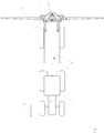
- Fig. 1 the distribution machine (1) is shown as a drawn sprayer, which is attached to a towing vehicle (2).
- a frame (3) is attached. This can have a device with the help of which the height of the frame (3) relative to the field sprayer (1) can be regulated.
- the frame (3) can also be rigidly connected to the field sprayer (1).
- the frame (3) is connected by means of a suspension device, here a pendulum suspension, which allows a substantially oriented in the direction of travel movement, with the central part (4) to which in turn the distributor linkage (6) is attached.
- a journal bearing by means of a sliding or linear ball bearing wherein the axis is oriented according to the direction of travel or a rail mounting.
- the in Fig. 1 shown middle part here is not essential to the invention and is assigned in the embodiment shown here the manifold linkage, since the distributor linkage is fixedly connected to the middle part and both movable relative to the frame by means of a suspension device (5), which is designed here as a pendulum guide is stored.
- the distributor linkage (6) can also be connected directly to the frame (3) via a bearing.
- the central part is associated with the frame and the distribution linkage is mounted via a movable suspension device movable relative to the central part and frame. It is also conceivable that between the frame and distribution linkage further parts of the distribution link or the frame can be assigned, which are connected to either the frame or the distributor linkage movable.
- the shuttle guide (5) of the distributor linkage (6) fulfills the purpose of making it movable parallel to the direction of travel R 1 and relative to the field sprayer (1) and its frame (3).
- the possible relative movement of the distributor linkage (6) and frame (3) can have further degrees of freedom.
- the bearing is designed, for example, as plain bearing or linear ball bearing along an axis lying in the direction of travel
- the distributor linkage (6) can additionally be rotated about the center of this axis in the direction of R 1 .
- the in Fig. 1 and Fig. 2 shown embodiment in which one side of the pendulum joint is designed as a ball head bearing. In a rail guide, however, this movement would be prevented.
- This also applies to another embodiment in which not one but two or more axles are used for guidance. Again, the rotational movement of the distributor linkage (6) about an axis parallel to R 1 would be prevented regardless of the storage on the axes.
- this is an acceleration sensor, but other sensors are conceivable, such as strain gauges or a speed sensor, which is used for the comparison of the current with a desired speed, so that future acceleration processes considered early for the scheme and the actuators and / or dampers corresponding the expected acceleration can be preconfigured.
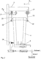
- Fig. 2 shown is a side view of the central part (4) and the frame (3).
- the central part (4) is in this case by means of a pendulum parallelogram suspension with two upper ball and socket joints (21) and two lower joints (22) and the two connecting the upper and lower joints pendulum rods (23) connected to the frame (3).
- the central part, to which the distributor linkage (6) is fixed designed to be movable in the direction of R 1 and pivotable about the axis A 2 through the ball joints.
- the storage takes place only via one or more than two bearings.
- the movement about the axis A 2 is not essential to the invention and can be prevented for example by appropriate multi-axis storage or rail guide.
- the control of the suspension device is provided as an active element (24).
- Data acquired by the sensor, not shown here, for example the acceleration, are compared as actual values with a desired value, for example by subtraction.
- the comparative value thus obtained is used in a control loop to generate an actuating signal which serves to control the active element and thus used to control the position of the central part (4) and thus indirectly of the distributor linkage, not shown here, attached to the central part, the control being instantaneous or quasi-instantaneously.
- the active element thus responds quasi without time delay or with minimal time delay on the data determined by the measuring device and prevents or damps the not shown here elastic bending or swinging of the ends of the distributor linkage.
- the active element (24) is shown here as a hydraulic cylinder. However, there are also any other forms of actuators conceivable, for example with a Pneumatic cylinder, a fluidic muscle, an electric motor or hydraulic motor.
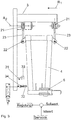
- FIG. 3 Another embodiment is in Fig. 3 shown.
- the central part (4) can be recognized, which is fastened to the frame (3) via the upper ball-and-socket joints (21), the lower joints (22) and the pendulum rods (23) connecting them.
- the active element has been replaced by a slowly active element (31). It consists of a spring element (32), for example a spiral spring, leaf spring or a hydraulic spring element, and a damper (33), which can be configured for example as a hydraulic or mechanical shock absorber, which between the frame (3) and the middle part (4).
- a spring element for example a spiral spring, leaf spring or a hydraulic spring element
- a damper which can be configured for example as a hydraulic or mechanical shock absorber, which between the frame (3) and the middle part (4).
- the comparative value thus obtained is used in a control loop to generate a control signal which serves to control the active element, here the spring base position by the double-acting cylinder, and thus to control the position of the central part (4) and thus indirectly of the distributor linkage not shown here ,
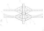
- Fig. 4 is exemplified the deflection of the sides of the distributor linkage (6) by an acceleration in the direction of R 4 acceleration.
- the distributor linkage (6) in this schematic diagram by two sliding bearings (41) and (42) on an axis along the direction of movement R 4 movably mounted.
- the described movements and bends can for a differently designed differently storage, such as the pendulum suspension in Fig. 2 and Fig. 3 be observed accordingly.
- An occurring acceleration can be caused for example by the start of the towing vehicle from the rest position.
- Shown is the distribution linkage (6), which is connected via the suspension device (44) with the front bearing (41) and the rear bearing (42).
- the front bearing (41) and the rear bearing (42) are in turn on the axis (43), arranged such that the distributor linkage (6) in and against the direction of travel R 4 relative to the axis (43) is displaceable.
- An onset of acceleration here exemplarily in the direction of R 4 , for example, by a starting operation of the towing vehicle, due to the flexibility of the manifold linkage (6) in conjunction with its dimensions and inertia, leads to an increasingly delayed acceleration towards the outer sides of the distributor linkage, which an elastic bending according to the position of the distributor linkage (6 ') and possibly induced thereby swinging up of the distributor linkage leads.
- This effect can be prevented or reduced by placing the linkage according to the position of the distribution linkage (6 ") depending on the thickness of the linkage Acceleration in the direction of R 5 moves and thus the occurring bending is encountered.
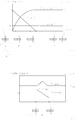
- Fig. 5 shows the speed of the field sprayer V field sprayer (t) as a function of time t when starting from the rest position
- the exact sequence of the acceleration process is not essential to the invention.
- the presented processes and processes for braking processes or accelerations apply from one movement.
- the acceleration course a frame (t) shown here applies to the field sprayer, the frame and also to a frame fixed to the frame linkage and takes place at time t 0 with maximum acceleration a 1 , which then decreases in a typical acceleration process the more the velocity v Field sprayer (t) approaches the target velocity v 0 .
- the acceleration is 0 m / s 2
- the speed of the field sprayer is then constant.
- the bending of the sides of a rigidly connected to the frame distributor linkage here depends directly on the acceleration occurring. The greater the acceleration, the greater the deflection of the distributor boom.
- the position of the distributor linkage (6) relative to the axle (43) during the acceleration process is also in FIG Fig. 5 shown.
- the distributor linkage (6) symbolized by the dashed line, for example in the center position (51) on the axis (43) (state A).
- This position is advantageous in order to mitigate acceleration processes in the direction R 4 and R 5 as well as possible, but also any other position on the axis (4) between the end points of the axis is conceivable as a starting position, although not in the same case for the case shown Dimensions suitable for damping occurring accelerations.
- the sensor-actuator combination of the invention ensures that acceleration acting on the distributor tube assembly (6) by moving the distributor tube assembly (6) on the axis (43) in which R 4 opposite direction R 5 is reduced.
- the distributor linkage (6) on the axis (43) for this purpose is counteracted towards the rear Direction R 4 moves (B).
- the position of the distributor linkage (6) on the axle (43) is in its extreme position (C) before being greater than t 2 , for example t 3, for times on the axis (43) in the direction of the central position (51) is moved forward (D), which is then reached at time t 4 .
- no more acceleration acts on the distributor linkage.
- control process other than the above-described control process are possible, for example, with successively decreasing or increasing acting on the manifold linkage (6) acceleration, which can act over a longer or shorter period than the acceleration of the towing vehicle (2) and the amount weaker or stronger than this one.
- short-term acceleration and / or braking operations may also be processes which are severely limited in time, as in the case illustrated in combination and thus caused bends and / or vibrations of the distributor linkage (6), which are caused, for example, by driving through a pothole.
- the speed of the traction vehicle (2) and / or the field sprayer (1) will change briefly when passing through the pothole and then preferably again assume the initial value, which was present before driving through the furrow.
- the acceleration of the distributor linkage (6) occurring as a result of the speed change and / or change in position of the field sprayer can be approximately prevented under these assumptions on the assumption that the control reacts instantaneously or quasi-instantly to the movement of the field sprayer, but at least considerably mitigates it.
- Fig. 6 shows by way of example the speed course v field sprayer (t) of the field sprayer when driving through a pothole.
- the speed of the field sprayer will increase briefly due to the acting acceleration by gravity and then reduce due to the force acting on the retraction braking effect of gravity approximately to the original value v const again.
- the shows Fig. 6 the course of the acceleration on the frame a frame (t), which when driving in a positive and positive when driving out of the pothole a negative acceleration Braking effect shows and influenced by the control acceleration of the distributor linkage (6) a Gestaenge (t), which can be reduced by the action of the sensor-actuator control to 0 m / s 2 .
- Vibrations can be integrated according to the invention by the consideration of acceleration and / or speed data and or position data and / or other parameters of the towing vehicle and / or field sprayer and / or the manifold linkage and / or in particular the boom of the manifold linkage in the control process, not only to prevent the bending, but also a swinging and / or swinging of the distributor linkage.
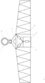
- FIG. 7 An embodiment according to the invention, which in addition to the displacement of the distributor linkage (6) relative to the frame (3) also allows a pendulum movement about the suspension point of a ball joint (71) is in Fig. 7 shown. Viewed from the manifold backside, the bearing shaft (72) is shown with the bearing (73) and the manifold linkage (6) attached to the suspension device (74). The pendulum movement is made possible by the ball joint (71) mounted between the suspension device (74) and the bearing (73). Actuators (75), which are exemplified here as double-acting hydraulic cylinders and mounted between the frame (3) and the distributor linkage (6), define a unique position of the distributor linkage (6) relative to the frame (3).
Landscapes
- Life Sciences & Earth Sciences (AREA)
- Engineering & Computer Science (AREA)
- Insects & Arthropods (AREA)
- Pest Control & Pesticides (AREA)
- Wood Science & Technology (AREA)
- Zoology (AREA)
- Environmental Sciences (AREA)
- Catching Or Destruction (AREA)
Priority Applications (1)
| Application Number | Priority Date | Filing Date | Title |
|---|---|---|---|
| PL15401080T PL2982243T3 (pl) | 2014-08-05 | 2015-08-03 | Urządzenie i sposób sterowania ruchem układu drążków rozdzielacza rolnego |
Applications Claiming Priority (1)
| Application Number | Priority Date | Filing Date | Title |
|---|---|---|---|
| DE102014111090.0A DE102014111090A1 (de) | 2014-08-05 | 2014-08-05 | Vorrichtung und Verfahren zur Bewegungssteuerung eines Verteilergestänges einer landwirtschaftlichen Verteilmaschine |
Publications (2)
| Publication Number | Publication Date |
|---|---|
| EP2982243A1 EP2982243A1 (de) | 2016-02-10 |
| EP2982243B1 true EP2982243B1 (de) | 2018-01-31 |
Family
ID=53800936
Family Applications (1)
| Application Number | Title | Priority Date | Filing Date |
|---|---|---|---|
| EP15401080.5A Active EP2982243B1 (de) | 2014-08-05 | 2015-08-03 | Vorrichtung und verfahren zur bewegungssteuerung eines verteilergestänges einer landwirtschaftlichen verteilmaschine |
Country Status (4)
| Country | Link |
|---|---|
| EP (1) | EP2982243B1 (pl) |
| DE (1) | DE102014111090A1 (pl) |
| DK (1) | DK2982243T3 (pl) |
| PL (1) | PL2982243T3 (pl) |
Families Citing this family (6)
| Publication number | Priority date | Publication date | Assignee | Title |
|---|---|---|---|---|
| DE102016110364A1 (de) | 2016-06-06 | 2017-12-07 | Amazonen-Werke H. Dreyer Gmbh & Co. Kg | Regel- und/oder Steuersystem, landwirtschaftliche Maschine und Verfahren zur Steuerung und/oder Regelung einer landwirtschaftlichen Maschine |
| DE102016114418A1 (de) * | 2016-08-04 | 2018-02-08 | Amazonen-Werke H. Dreyer Gmbh & Co. Kg | Verteilergestänge, landwirtschaftliches Nutzfahrzeug und Verfahren zur Herstellung eines Verteilergestänges |
| DE102017201918A1 (de) * | 2017-02-07 | 2018-08-09 | Deere & Company | Landwirtschaftliche Verteilmaschine mit selbsttätiger Kontrolle der Dämpfung des Verteilergestänges |
| DE102017114637A1 (de) | 2017-06-07 | 2018-12-13 | Amazonen-Werke H. Dreyer Gmbh & Co. Kg | Spritzeinrichtung für ein landwirtschaftliches Spritzgerät Durchflussmengenregelung |
| DE102017118302A1 (de) * | 2017-08-11 | 2019-02-14 | Amazonen-Werke H. Dreyer Gmbh & Co. Kg | Steuer- und/oder Regelsystem, landwirtschaftliches Nutzfahrzeug und Verfahren zur Steuerung und/oder Regelung eines landwirtschaftlichen Nutzfahrzeuges |
| CN108782527A (zh) * | 2018-06-22 | 2018-11-13 | 苏州仁益生物科技有限公司 | 一种可移动式农业种植用灌溉装置 |
Family Cites Families (7)
| Publication number | Priority date | Publication date | Assignee | Title |
|---|---|---|---|---|
| FR2530498A1 (fr) * | 1982-07-26 | 1984-01-27 | Sba Chimie | Dispositif de montage de rampes adaptees sur des materiels agricoles et industriels, en particulier des rampes de pulverisation |
| US4646972A (en) * | 1984-10-22 | 1987-03-03 | Cedar Valley Products, Inc. | Spring mounted spray boom structure |
| DE20018716U1 (de) | 1999-11-04 | 2001-03-29 | Inuma Fahrzeug-Service Und Maschinenbau Gmbh, 99958 Aschara | Vorrichtung zur Befestigung von Spritzgestängen an landwirtschaftlichen Fahrzeugen |
| DE10054285B4 (de) | 2000-11-02 | 2014-12-24 | Amazonen-Werke H. Dreyer Gmbh & Co. Kg | Verteilmaschine |
| DE102007025751B4 (de) | 2007-06-01 | 2022-08-25 | Amazonen-Werke H. Dreyer SE & Co. KG | Verteilmaschine |
| DE102008007312A1 (de) | 2008-02-02 | 2009-08-06 | Amazonen-Werke H. Dreyer Gmbh & Co. Kg | Verteilergestänge |
| EP3219187B1 (de) | 2011-11-08 | 2023-10-04 | HORSCH LEEB Application Systems GmbH | Fahrbare vorrichtung zum ausbringen von flüssigen und/oder festen wirkstoffen und verfahren zur steuerung der vorrichtung |
-
2014
- 2014-08-05 DE DE102014111090.0A patent/DE102014111090A1/de not_active Withdrawn
-
2015
- 2015-08-03 PL PL15401080T patent/PL2982243T3/pl unknown
- 2015-08-03 EP EP15401080.5A patent/EP2982243B1/de active Active
- 2015-08-03 DK DK15401080.5T patent/DK2982243T3/en active
Non-Patent Citations (1)
| Title |
|---|
| None * |
Also Published As
| Publication number | Publication date |
|---|---|
| EP2982243A1 (de) | 2016-02-10 |
| DK2982243T3 (en) | 2018-05-07 |
| PL2982243T3 (pl) | 2018-07-31 |
| DE102014111090A1 (de) | 2016-02-11 |
Similar Documents
| Publication | Publication Date | Title |
|---|---|---|
| EP2982243B1 (de) | Vorrichtung und verfahren zur bewegungssteuerung eines verteilergestänges einer landwirtschaftlichen verteilmaschine | |
| EP2829177B1 (de) | Landwirtschaftliche Verteilmaschine mit Verteilvorrichtung und System zur Steuerung der Verteilvorrichtung | |
| DE602004004297T2 (de) | System und Verfahren für die Rollregelung eines aufgehängten Gestänges | |
| EP3065530B1 (de) | Vorrichtung zum ausbringen von flüssigen und/oder festen wirkstoffen und verfahren zur steuerung einer solchen vorrichtung | |
| EP3219187B1 (de) | Fahrbare vorrichtung zum ausbringen von flüssigen und/oder festen wirkstoffen und verfahren zur steuerung der vorrichtung | |
| EP3337317B1 (de) | Aufhängung für ein verteilergestänge einer landwirtschaftlichen maschine | |
| EP2837285B1 (de) | Spritzgestänge einer landwirtschaftlichen Feldspritze | |
| EP3634124B1 (de) | Verteilergestänge | |
| EP3753407B1 (de) | Landwirtschaftliches gerät mit verbesserter neigungsregelung | |
| EP4212018A1 (de) | Landwirtschaftliches gerät mit verbesserter neigungsregelung | |
| EP2526755A1 (de) | Landwirtschaftliche Verteilmaschine | |
| EP3440932B1 (de) | Aktive schwingungsdämpfung | |
| EP3141114B1 (de) | Flächenausbringanordnung sowie flächenausbringsteuerungsverfahren | |
| DE202013011983U1 (de) | Spritzgestänge einer landwirtschaftlichen Feldspritze | |
| EP3308644A1 (de) | Regel- und/oder steuersystem für eine landwirtschaftliche maschine | |
| DE102018103862A1 (de) | Aufhängung für eine landwirtschaftliche Maschine und Verfahren zum Betreiben einer landwirtschaftlichen Maschine | |
| DE102008017058B4 (de) | Seitensteuerung für eine Vibrationsplatte | |
| DE102006023603B4 (de) | Vorrichtung und Verfahren zur Kompensation eines dynamischen Giermomentes | |
| DE1269902B (de) | Verfahren und Einrichtung zum Steuern einer Fahrzeugfederung, insbesondere bei gelaendegaengigen Kraftfahrzeugen | |
| EP2526756B1 (de) | Landwirtschaftliche Verteilmaschine mit Verteilergestänge | |
| EP3798028B1 (de) | Landwirtschaftliche arbeitsmaschine und verfahren zum lenken einer landwirtschaftlichen arbeitsmaschine | |
| DE102022124012A1 (de) | Landwirtschaftliche Erntemaschine, insbesondere in Form eines Frontmähwerks | |
| DE102022131013A1 (de) | Landwirtschaftliche Erntemaschine | |
| WO2008017371A1 (de) | Verfahren zum unterstopfen und stabilisieren eines gleises |
Legal Events
| Date | Code | Title | Description |
|---|---|---|---|
| PUAI | Public reference made under article 153(3) epc to a published international application that has entered the european phase |
Free format text: ORIGINAL CODE: 0009012 |
|
| AK | Designated contracting states |
Kind code of ref document: A1 Designated state(s): AL AT BE BG CH CY CZ DE DK EE ES FI FR GB GR HR HU IE IS IT LI LT LU LV MC MK MT NL NO PL PT RO RS SE SI SK SM TR |
|
| AX | Request for extension of the european patent |
Extension state: BA ME |
|
| 17P | Request for examination filed |
Effective date: 20160809 |
|
| RBV | Designated contracting states (corrected) |
Designated state(s): AL AT BE BG CH CY CZ DE DK EE ES FI FR GB GR HR HU IE IS IT LI LT LU LV MC MK MT NL NO PL PT RO RS SE SI SK SM TR |
|
| RIC1 | Information provided on ipc code assigned before grant |
Ipc: A01M 7/00 20060101AFI20170725BHEP |
|
| GRAP | Despatch of communication of intention to grant a patent |
Free format text: ORIGINAL CODE: EPIDOSNIGR1 |
|
| INTG | Intention to grant announced |
Effective date: 20171026 |
|
| GRAS | Grant fee paid |
Free format text: ORIGINAL CODE: EPIDOSNIGR3 |
|
| GRAA | (expected) grant |
Free format text: ORIGINAL CODE: 0009210 |
|
| AK | Designated contracting states |
Kind code of ref document: B1 Designated state(s): AL AT BE BG CH CY CZ DE DK EE ES FI FR GB GR HR HU IE IS IT LI LT LU LV MC MK MT NL NO PL PT RO RS SE SI SK SM TR |
|
| REG | Reference to a national code |
Ref country code: GB Ref legal event code: FG4D Free format text: NOT ENGLISH Ref country code: CH Ref legal event code: EP |
|
| REG | Reference to a national code |
Ref country code: AT Ref legal event code: REF Ref document number: 966503 Country of ref document: AT Kind code of ref document: T Effective date: 20180215 |
|
| REG | Reference to a national code |
Ref country code: IE Ref legal event code: FG4D Free format text: LANGUAGE OF EP DOCUMENT: GERMAN |
|
| REG | Reference to a national code |
Ref country code: DE Ref legal event code: R096 Ref document number: 502015002968 Country of ref document: DE |
|
| REG | Reference to a national code |
Ref country code: NL Ref legal event code: FP |
|
| REG | Reference to a national code |
Ref country code: DK Ref legal event code: T3 Effective date: 20180504 |
|
| REG | Reference to a national code |
Ref country code: LT Ref legal event code: MG4D |
|
| REG | Reference to a national code |
Ref country code: FR Ref legal event code: PLFP Year of fee payment: 4 |
|
| PG25 | Lapsed in a contracting state [announced via postgrant information from national office to epo] |
Ref country code: ES Free format text: LAPSE BECAUSE OF FAILURE TO SUBMIT A TRANSLATION OF THE DESCRIPTION OR TO PAY THE FEE WITHIN THE PRESCRIBED TIME-LIMIT Effective date: 20180131 Ref country code: NO Free format text: LAPSE BECAUSE OF FAILURE TO SUBMIT A TRANSLATION OF THE DESCRIPTION OR TO PAY THE FEE WITHIN THE PRESCRIBED TIME-LIMIT Effective date: 20180430 Ref country code: HR Free format text: LAPSE BECAUSE OF FAILURE TO SUBMIT A TRANSLATION OF THE DESCRIPTION OR TO PAY THE FEE WITHIN THE PRESCRIBED TIME-LIMIT Effective date: 20180131 Ref country code: FI Free format text: LAPSE BECAUSE OF FAILURE TO SUBMIT A TRANSLATION OF THE DESCRIPTION OR TO PAY THE FEE WITHIN THE PRESCRIBED TIME-LIMIT Effective date: 20180131 Ref country code: LT Free format text: LAPSE BECAUSE OF FAILURE TO SUBMIT A TRANSLATION OF THE DESCRIPTION OR TO PAY THE FEE WITHIN THE PRESCRIBED TIME-LIMIT Effective date: 20180131 |
|
| PG25 | Lapsed in a contracting state [announced via postgrant information from national office to epo] |
Ref country code: BG Free format text: LAPSE BECAUSE OF FAILURE TO SUBMIT A TRANSLATION OF THE DESCRIPTION OR TO PAY THE FEE WITHIN THE PRESCRIBED TIME-LIMIT Effective date: 20180430 Ref country code: LV Free format text: LAPSE BECAUSE OF FAILURE TO SUBMIT A TRANSLATION OF THE DESCRIPTION OR TO PAY THE FEE WITHIN THE PRESCRIBED TIME-LIMIT Effective date: 20180131 Ref country code: SE Free format text: LAPSE BECAUSE OF FAILURE TO SUBMIT A TRANSLATION OF THE DESCRIPTION OR TO PAY THE FEE WITHIN THE PRESCRIBED TIME-LIMIT Effective date: 20180131 Ref country code: IS Free format text: LAPSE BECAUSE OF FAILURE TO SUBMIT A TRANSLATION OF THE DESCRIPTION OR TO PAY THE FEE WITHIN THE PRESCRIBED TIME-LIMIT Effective date: 20180531 Ref country code: GR Free format text: LAPSE BECAUSE OF FAILURE TO SUBMIT A TRANSLATION OF THE DESCRIPTION OR TO PAY THE FEE WITHIN THE PRESCRIBED TIME-LIMIT Effective date: 20180501 Ref country code: RS Free format text: LAPSE BECAUSE OF FAILURE TO SUBMIT A TRANSLATION OF THE DESCRIPTION OR TO PAY THE FEE WITHIN THE PRESCRIBED TIME-LIMIT Effective date: 20180131 |
|
| PG25 | Lapsed in a contracting state [announced via postgrant information from national office to epo] |
Ref country code: MT Free format text: LAPSE BECAUSE OF FAILURE TO SUBMIT A TRANSLATION OF THE DESCRIPTION OR TO PAY THE FEE WITHIN THE PRESCRIBED TIME-LIMIT Effective date: 20180131 |
|
| PG25 | Lapsed in a contracting state [announced via postgrant information from national office to epo] |
Ref country code: RO Free format text: LAPSE BECAUSE OF FAILURE TO SUBMIT A TRANSLATION OF THE DESCRIPTION OR TO PAY THE FEE WITHIN THE PRESCRIBED TIME-LIMIT Effective date: 20180131 Ref country code: AL Free format text: LAPSE BECAUSE OF FAILURE TO SUBMIT A TRANSLATION OF THE DESCRIPTION OR TO PAY THE FEE WITHIN THE PRESCRIBED TIME-LIMIT Effective date: 20180131 Ref country code: EE Free format text: LAPSE BECAUSE OF FAILURE TO SUBMIT A TRANSLATION OF THE DESCRIPTION OR TO PAY THE FEE WITHIN THE PRESCRIBED TIME-LIMIT Effective date: 20180131 |
|
| REG | Reference to a national code |
Ref country code: DE Ref legal event code: R097 Ref document number: 502015002968 Country of ref document: DE |
|
| PG25 | Lapsed in a contracting state [announced via postgrant information from national office to epo] |
Ref country code: SM Free format text: LAPSE BECAUSE OF FAILURE TO SUBMIT A TRANSLATION OF THE DESCRIPTION OR TO PAY THE FEE WITHIN THE PRESCRIBED TIME-LIMIT Effective date: 20180131 Ref country code: SK Free format text: LAPSE BECAUSE OF FAILURE TO SUBMIT A TRANSLATION OF THE DESCRIPTION OR TO PAY THE FEE WITHIN THE PRESCRIBED TIME-LIMIT Effective date: 20180131 |
|
| PLBE | No opposition filed within time limit |
Free format text: ORIGINAL CODE: 0009261 |
|
| STAA | Information on the status of an ep patent application or granted ep patent |
Free format text: STATUS: NO OPPOSITION FILED WITHIN TIME LIMIT |
|
| 26N | No opposition filed |
Effective date: 20181102 |
|
| PG25 | Lapsed in a contracting state [announced via postgrant information from national office to epo] |
Ref country code: SI Free format text: LAPSE BECAUSE OF FAILURE TO SUBMIT A TRANSLATION OF THE DESCRIPTION OR TO PAY THE FEE WITHIN THE PRESCRIBED TIME-LIMIT Effective date: 20180131 |
|
| PG25 | Lapsed in a contracting state [announced via postgrant information from national office to epo] |
Ref country code: MC Free format text: LAPSE BECAUSE OF FAILURE TO SUBMIT A TRANSLATION OF THE DESCRIPTION OR TO PAY THE FEE WITHIN THE PRESCRIBED TIME-LIMIT Effective date: 20180131 |
|
| REG | Reference to a national code |
Ref country code: CH Ref legal event code: PL |
|
| PG25 | Lapsed in a contracting state [announced via postgrant information from national office to epo] |
Ref country code: LI Free format text: LAPSE BECAUSE OF NON-PAYMENT OF DUE FEES Effective date: 20180831 Ref country code: LU Free format text: LAPSE BECAUSE OF NON-PAYMENT OF DUE FEES Effective date: 20180803 Ref country code: CH Free format text: LAPSE BECAUSE OF NON-PAYMENT OF DUE FEES Effective date: 20180831 |
|
| REG | Reference to a national code |
Ref country code: BE Ref legal event code: MM Effective date: 20180831 |
|
| REG | Reference to a national code |
Ref country code: IE Ref legal event code: MM4A |
|
| PG25 | Lapsed in a contracting state [announced via postgrant information from national office to epo] |
Ref country code: IE Free format text: LAPSE BECAUSE OF NON-PAYMENT OF DUE FEES Effective date: 20180803 |
|
| PG25 | Lapsed in a contracting state [announced via postgrant information from national office to epo] |
Ref country code: BE Free format text: LAPSE BECAUSE OF NON-PAYMENT OF DUE FEES Effective date: 20180831 |
|
| PG25 | Lapsed in a contracting state [announced via postgrant information from national office to epo] |
Ref country code: TR Free format text: LAPSE BECAUSE OF FAILURE TO SUBMIT A TRANSLATION OF THE DESCRIPTION OR TO PAY THE FEE WITHIN THE PRESCRIBED TIME-LIMIT Effective date: 20180131 |
|
| GBPC | Gb: european patent ceased through non-payment of renewal fee |
Effective date: 20190803 |
|
| PG25 | Lapsed in a contracting state [announced via postgrant information from national office to epo] |
Ref country code: PT Free format text: LAPSE BECAUSE OF FAILURE TO SUBMIT A TRANSLATION OF THE DESCRIPTION OR TO PAY THE FEE WITHIN THE PRESCRIBED TIME-LIMIT Effective date: 20180131 |
|
| PG25 | Lapsed in a contracting state [announced via postgrant information from national office to epo] |
Ref country code: CY Free format text: LAPSE BECAUSE OF FAILURE TO SUBMIT A TRANSLATION OF THE DESCRIPTION OR TO PAY THE FEE WITHIN THE PRESCRIBED TIME-LIMIT Effective date: 20180131 Ref country code: HU Free format text: LAPSE BECAUSE OF FAILURE TO SUBMIT A TRANSLATION OF THE DESCRIPTION OR TO PAY THE FEE WITHIN THE PRESCRIBED TIME-LIMIT; INVALID AB INITIO Effective date: 20150803 Ref country code: MK Free format text: LAPSE BECAUSE OF NON-PAYMENT OF DUE FEES Effective date: 20180131 |
|
| PG25 | Lapsed in a contracting state [announced via postgrant information from national office to epo] |
Ref country code: GB Free format text: LAPSE BECAUSE OF NON-PAYMENT OF DUE FEES Effective date: 20190803 |
|
| REG | Reference to a national code |
Ref country code: DE Ref legal event code: R081 Ref document number: 502015002968 Country of ref document: DE Owner name: AMAZONEN-WERKE H. DREYER SE & CO. KG, DE Free format text: FORMER OWNER: AMAZONEN-WERKE H. DREYER GMBH & CO. KG, 49205 HASBERGEN, DE |
|
| REG | Reference to a national code |
Ref country code: AT Ref legal event code: MM01 Ref document number: 966503 Country of ref document: AT Kind code of ref document: T Effective date: 20200803 |
|
| PG25 | Lapsed in a contracting state [announced via postgrant information from national office to epo] |
Ref country code: AT Free format text: LAPSE BECAUSE OF NON-PAYMENT OF DUE FEES Effective date: 20200803 |
|
| P01 | Opt-out of the competence of the unified patent court (upc) registered |
Effective date: 20230523 |
|
| PGFP | Annual fee paid to national office [announced via postgrant information from national office to epo] |
Ref country code: PL Payment date: 20250612 Year of fee payment: 11 |
|
| PGFP | Annual fee paid to national office [announced via postgrant information from national office to epo] |
Ref country code: NL Payment date: 20250613 Year of fee payment: 11 |
|
| PGFP | Annual fee paid to national office [announced via postgrant information from national office to epo] |
Ref country code: FR Payment date: 20250610 Year of fee payment: 11 |
|
| PGFP | Annual fee paid to national office [announced via postgrant information from national office to epo] |
Ref country code: DK Payment date: 20250814 Year of fee payment: 11 Ref country code: DE Payment date: 20250611 Year of fee payment: 11 |
|
| PGFP | Annual fee paid to national office [announced via postgrant information from national office to epo] |
Ref country code: IT Payment date: 20250722 Year of fee payment: 11 |
|
| PGFP | Annual fee paid to national office [announced via postgrant information from national office to epo] |
Ref country code: CZ Payment date: 20250723 Year of fee payment: 11 |