EP2980997A1 - Système de communication sans fil - Google Patents
Système de communication sans fil Download PDFInfo
- Publication number
- EP2980997A1 EP2980997A1 EP14775250.5A EP14775250A EP2980997A1 EP 2980997 A1 EP2980997 A1 EP 2980997A1 EP 14775250 A EP14775250 A EP 14775250A EP 2980997 A1 EP2980997 A1 EP 2980997A1
- Authority
- EP
- European Patent Office
- Prior art keywords
- reception
- transmission
- frequency
- filter
- signal
- Prior art date
- Legal status (The legal status is an assumption and is not a legal conclusion. Google has not performed a legal analysis and makes no representation as to the accuracy of the status listed.)
- Withdrawn
Links
Images


Classifications
-
- H—ELECTRICITY
- H04—ELECTRIC COMMUNICATION TECHNIQUE
- H04J—MULTIPLEX COMMUNICATION
- H04J1/00—Frequency-division multiplex systems
- H04J1/02—Details
- H04J1/10—Intermediate station arrangements, e.g. for branching, for tapping-off
-
- H—ELECTRICITY
- H04—ELECTRIC COMMUNICATION TECHNIQUE
- H04B—TRANSMISSION
- H04B1/00—Details of transmission systems, not covered by a single one of groups H04B3/00 - H04B13/00; Details of transmission systems not characterised by the medium used for transmission
- H04B1/005—Details of transmission systems, not covered by a single one of groups H04B3/00 - H04B13/00; Details of transmission systems not characterised by the medium used for transmission adapting radio receivers, transmitters andtransceivers for operation on two or more bands, i.e. frequency ranges
- H04B1/0064—Details of transmission systems, not covered by a single one of groups H04B3/00 - H04B13/00; Details of transmission systems not characterised by the medium used for transmission adapting radio receivers, transmitters andtransceivers for operation on two or more bands, i.e. frequency ranges with separate antennas for the more than one band
-
- H—ELECTRICITY
- H04—ELECTRIC COMMUNICATION TECHNIQUE
- H04W—WIRELESS COMMUNICATION NETWORKS
- H04W72/00—Local resource management
- H04W72/04—Wireless resource allocation
- H04W72/044—Wireless resource allocation based on the type of the allocated resource
- H04W72/0453—Resources in frequency domain, e.g. a carrier in FDMA
-
- H—ELECTRICITY
- H04—ELECTRIC COMMUNICATION TECHNIQUE
- H04B—TRANSMISSION
- H04B1/00—Details of transmission systems, not covered by a single one of groups H04B3/00 - H04B13/00; Details of transmission systems not characterised by the medium used for transmission
- H04B1/38—Transceivers, i.e. devices in which transmitter and receiver form a structural unit and in which at least one part is used for functions of transmitting and receiving
- H04B1/40—Circuits
- H04B1/50—Circuits using different frequencies for the two directions of communication
Definitions
- the present invention relates to a wireless communication system that is constituted with a wireless communication device such as RRH (Remote Radio Head) used for mobile phone base stations.
- RRH Remote Radio Head
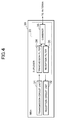
- FIG. 4 is a block diagram showing RRH of Related Technique 1. Hereinafter, explanations will be provided by referring to the drawing.
- An RRH 30 includes: a transmission circuit unit 31 which outputs transmission signals; a reception circuit unit 32 which inputs reception signals; and a duplexer 33 provided between the transmission circuit unit 31, the reception circuit unit 32, and an antenna, which lets through only the transmission signals from the transmission circuit unit 31 to the antenna via a transmission filter 34 and lets through only the reception signals from the antenna to the reception circuit unit 32 via a reception filter 35.
- the duplexer 33 includes: the transmission filter 34 which lets through only the signals of the transmission frequency; the reception filter 35 which lets through only the signals of the reception frequency; and a combiner 36 which outputs the signals transmitted through the transmission filter 34 to the antenna and outputs the signals received by the antenna to the reception filter 35.
- the RRH 30 includes the transmission circuit unit 31 and the reception circuit unit 32 inside thereof, and the transmission circuit unit 31 and the reception circuit unit 32 are connected to the antenna via the duplexer 33 in which the combiner 36, the transmission filter 34, and the reception filter 35 are integrated.
- the transmission signal outputted from the transmission circuit unit 31 is recognized as an interference wave of an extremely high level from the reception circuit 32 side. For example, when the transmission output is the RRH 30 of 20 W, the difference between the minimum value of the reception signal and the maximum value of the transmission signal becomes 140 dB or more.
- the reception filter 35 it is necessary for the reception filter 35 to have a large attenuation amount (80 dB or more) of the frequency band of the transmission signal while decreasing the attenuation (loss) amount of the frequency band of the reception signal.
- the transmission frequency and the reception frequency are different frequencies but are quite close.
- the transmission frequency is 2110 to 2170 MHz and the reception frequency is 1920 to 1980 MHz in "3GPP E UTRA Operating Band 1", and the distance therebetween is 190 MHz. Therefore, in order to reduce the loss of the reception band and to increase the attenuation of the transmission band as the two required performances of the reception filter 35 at the same time, an extremely steep characteristic is required for the reception filter 35.
- There are some methods for achieving the steep characteristic of the filter However, when the materials, process precision, and the like are the same, it is necessary to increase the number of stages. Thus, the filter of the steeper characteristic cannot avoid becoming large-scaled.
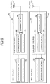
- FIG. 5 is a block diagram showing a wireless communication system of Related Technique 2.
- FIG. 6 is a graph showing the filter characteristic of a reception filter according to Related Technique 2.
- FIG. 5 and FIG. 6 explanations will be provided by referring to FIG. 5 and FIG. 6 .
- the wireless communication system according to Related Technique 2 includes an RRH 40 and an RRH 50.
- the RRH 40 includes: a transmission circuit unit 41 which outputs a first transmission signal constituted with a transmission frequency TX1; a reception circuit unit 42 which inputs a first reception signal constituted with a reception frequency signal RX1; an antenna 47 which transmits and receives the first transmission signal and the first reception signal; and a duplexer 43 provided between the transmission circuit unit 41, the reception circuit unit 42, and the antenna 47, which lets through only the first transmission signal from the transmission circuit unit 41 to the antenna 47 via a transmission filter 44 and lets through only the first reception signal from the antenna 47 to the reception circuit unit 42 via a reception filter 45.
- the duplexer 43 includes: the transmission filter 44 which lets through only the signal of the transmission frequency TX1; the reception filter 45 which lets through only the signal of the reception frequency RX1; and a combiner 46 which outputs the signals transmitted through the transmission filter 44 to the antenna 47 and outputs the signals received by the antenna 47 to the reception filter 45.
- the RRH 50 includes: a transmission circuit unit 51 which outputs a second transmission signal constituted with a transmission frequency TX2; a reception circuit unit 52 which inputs a second reception signal constituted with a reception frequency signal RX2; an antenna 57 which transmits and receives the second transmission signal and the second reception signal; and a duplexer 53 provided between the transmission circuit unit 51, the reception circuit unit 52, and the antenna 57, which lets through only the second transmission signal from the transmission circuit unit 51 to the antenna 57 via a transmission filter 54 and lets through only the second reception signal from the antenna 57 to the reception circuit unit 52 via a reception filter 55.
- the duplexer 53 includes: the transmission filter 54 which lets through only the signal of the transmission frequency TX2; the reception filter 55 which lets through only the signal of the reception frequency RX2; and a combiner 56 which outputs the signals transmitted through the transmission filter 54 to the antenna 57 and outputs the signals received by the antenna 57 to the reception filter 55.
- the lateral axis shows the frequency and the longitudinal axis shows the filter attenuation amount.
- the attenuation amount of the reception filter 45 is shown with an alternate long dashed and short dashed line
- the attenuation amount of the transmission filter 55 is shown with an alternate long dashed and double short dashed line.
- the relations regarding the transmission frequency TX1, the reception frequency RX1, the transmission frequency TX2, and the reception frequency RX2 can be expressed as follows provided that the frequencies are defined as fTX1, fRX1, fTX2, and fRX2, respectively. fRX ⁇ 1 ⁇ fTX ⁇ 1 ⁇ fRX ⁇ 2 ⁇ fTX ⁇ 2
- a technique called “carrier aggregation” which increases the speed of data transfer by considering a plurality of frequency bands as a single transmission band all together is specified.
- two RRHs are connected to a single antenna via a combiner. Whether to share a single antenna by a plurality of RRHs via a combiner or to use separate antennas by each RRH is determined according to a trade-off relation between the cost of the antenna and the cost of the combiner.
- FIG. 5 shows the form thereof. In the drawing, the two RRHs 40 and 50 are connected to the different antennas 47 and 57.
- Patent Document 1 Japanese Unexamined Patent Publication 2012-222467
- each of the two RRHs 40 and 50 corresponding to the two frequency bands is prepared as shown in FIG. 5 . It is assumed here that the positional relation of each of the frequency bands on the frequency axis is in a form as shown in FIG. 6 . In this case, the reception filters 45 and 55 within the respective RRHs 40 and 50 are required to have the characteristics shown in FIG. 6 as described above.
- the attenuation amount of the band of the reception frequency RX1 is set to be small while the attenuation amount of the band of the transmission frequency TX1 is set to be large.
- the attenuation amount of the band of the reception frequency RX2 is set to be small while the attenuation amount of the band of the transmission frequency TX2 is set to be large.
- the slope of the part surrounded by a broken line in FIG. 6 is required to be steep, and it determines the sizes of the reception filters 45 and 55.
- the proportion of the duplexers 13 and 23 occupying the entire volume of the RRHs 40 and 50 is large (about 20 to 50 %), so that the sizes of the duplexers 13 and 23 determine the sizes of the RHs 40 and 50 themselves.
- the wireless communication system includes a first wireless communication device and a second wireless communication device, wherein: the first wireless communication device includes a first transmission circuit unit which outputs a first transmission signal constituted with a first transmission frequency, a first reception circuit unit which inputs a first reception signal constituted with a second reception frequency, a first antenna which transmits and receives the first transmission signal and the first reception signal, and a first duplexer provided between the first transmission circuit unit, the first reception circuit unit, and the first antenna, which lets through only the first transmission signal from the first transmission circuit unit to the first antenna via a first transmission filter and lets through only the first reception signal from the first antenna to the first reception circuit unit via a first reception filter; the second wireless communication device includes a second transmission circuit unit which outputs a second transmission signal constituted with a second transmission frequency, a second reception circuit unit which inputs a second reception signal constituted with a first reception frequency, a second antenna which transmits and receives the second transmission signal and the second reception signal, and a second duplexer provided between
- the first reception filter separates the first transmission frequency and the first reception frequency while the second reception filter separates the second transmission frequency and the second reception frequency.
- the first reception filter separates the first transmission frequency and the second reception frequency while the second reception filter separates the second transmission frequency and the first reception frequency, thereby making it possible to decrease the sizes of the first and second reception filters of the present invention.
- the reason thereof is that the difference between the first transmission frequency and the second reception frequency and the difference between the second transmission frequency and the first reception frequency are both greater than the difference between the first transmission frequency and the first reception frequency and the difference between the second transmission frequency and the second reception frequency, so that the first and second reception filters of the present invention do not require a steeper filter characteristic compared to the first and second reception filters of the related technique.
- FIG. 1 is a block diagram showing a wireless communication system of a first embodiment.
- FIG. 2 is a first graph showing the filter characteristic of a reception filter according to the first embodiment.
- FIG. 3 is a second graph showing the filter characteristic of the reception filter according to the first embodiment.
- the wireless communication system includes an RRH 10 as a first wireless communication device and an RRH 20 as a second wireless communication device.
- the RRH 10 corresponds to a first transmission frequency TX1 and a second reception frequency RX2.
- a first transmission circuit unit 11 is an electric circuit corresponding to a transmission frequency TX1.
- a first reception circuit unit 12 is an electric circuit corresponding to a reception frequency RX2.
- a first duplexer 13 corresponds to the transmission frequency TX1 and the reception frequency RX2.
- a first transmission filter 14 is a band-pass filter corresponding to the transmission frequency TX1.
- a first reception filter 15 is a band-pass filter corresponding to the reception frequency RX2.
- a first combiner 16 connects the transmission circuit unit 11 side and the reception circuit unit 12 side.
- a first antenna 17 is for the RRH 10 which uses the transmission frequency TX1 and the reception frequency RX2.
- the RRH 20 corresponds to a second transmission frequency TX2 and a first reception frequency RX1.
- a second transmission circuit unit 21 is an electric circuit corresponding to a transmission frequency TX2.
- a second reception circuit unit 22 is an electric circuit corresponding to a reception frequency RX1.
- a second duplexer 23 corresponds to the transmission frequency TX2 and the reception frequency RX1.
- a second transmission filter 24 is a band-pass filter corresponding to the transmission frequency TX2.
- a second reception filter 25 is a band-pass filter corresponding to the reception frequency RX1.
- a second combiner 16 connects the transmission circuit unit 21 side and the reception circuit unit 22 side.
- a second antenna 27 is for the RRH 20 which uses the transmission frequency TX2 and the reception frequency RX1.
- the RRH 10 includes: the transmission circuit unit 11 which outputs a first transmission signal constituted with the transmission frequency TX1; the reception circuit unit 12 which inputs a first reception signal constituted with the reception frequency signal RX2; the antenna 17 which transmits and receives the first transmission signal and the first reception signal; and the duplexer 13 provided between the transmission circuit unit 11, the reception circuit unit 12, and the antenna 17, which lets through only the first transmission signal from the transmission circuit unit 11 to the antenna 17 via the transmission filter 14 and lets through only the first reception signal from the antenna 17 to the reception circuit unit 12 via the reception filter 15.
- the duplexer 13 includes: the transmission filter 14 which lets through only the signal of the transmission frequency TX2; the reception filter 15 which lets through only the signal of the reception frequency RX2; and the combiner 16 which outputs the signals transmitted through the transmission filter 14 to the antenna 17 and outputs the signals received by the antenna 17 to the reception filter 15.
- the RRH 20 includes: the transmission circuit unit 21 which outputs a second transmission signal constituted with the transmission frequency TX2; the reception circuit unit 22 which inputs a second reception signal constituted with the reception frequency signal RX1; the antenna 27 which transmits and receives the second transmission signal and the second reception signal; and the duplexer 23 provided between the transmission circuit unit 21, the reception circuit unit 22, and the antenna 27, which lets through only the second transmission signal from the transmission circuit unit 21 to the antenna 27 via the transmission filter 24 and lets through only the second reception signal from the antenna 27 to the reception circuit unit 22 via the reception filter 25.
- the duplexer 23 includes: the transmission filter 24 which lets through only the signal of the transmission frequency TX2; the reception filter 25 which lets through only the signal of the reception frequency RX2; and the combiner 26 which outputs the signals transmitted through the transmission filter 24 to the antenna 27 and outputs the signals received by the antenna 27 to the reception filter 25.
- the lateral axis shows the frequency and the longitudinal axis shows the filter attenuation amount.
- the attenuation amount of the reception filter 25 is shown with an alternate long dashed and short dashed line
- the attenuation amount of the transmission filter 15 is shown with an alternate long dashed and double short dashed line.
- the relations regarding the transmission frequency TX1, the reception frequency RX1, the transmission frequency TX2, and the reception frequency RX2 can be expressed as follows provided that the frequencies are defined as fTX1, fRX1, fTX2, and fRX2, respectively. fRX ⁇ 1 ⁇ fTX ⁇ 1 ⁇ fTX ⁇ 2 ⁇ fRX ⁇ 2
- a difference f(TX1 - RX2) between the transmission frequency TX1 and the reception frequency RX2 and a difference f(TX2 - RX1) between the transmission frequency TX2 and the reception frequency RX1 are both greater than a difference f (TX1 - RX1) between the transmission frequency TX1 and the reception frequency RX1 and a difference f (TX2 - RX2) between the transmission frequency TX2 and the reception frequency RX2.
- the reception filter 45 separates the transmission frequency TX1 and the reception frequency RX1 while the reception filter 55 separates the transmission frequency TX2 and the reception frequency RX2.
- the reception filter 15 separates the transmission frequency TX1 and the reception frequency RX2 while the reception filter 25 separates the transmission frequency TX2 and the reception frequency RX1, thereby making it possible to decrease the sizes of the reception filters 15 and 25 of the first embodiment.
- the difference f (TX1 - RX2) between the transmission frequency TX1 and the reception frequency RX2 and the difference f (TX2 - RX1) between the transmission frequency TX2 and the reception frequency RX1 are both greater than the difference f (TX1 - RX1) between the transmission frequency TX1 and the reception frequency RX1 and the difference f(TX2 - RX2) between the transmission frequency TX2 and the reception frequency RX2, so that the reception filters 15, 25 of the first embodiment do not require a steeper filter characteristic compared to the reception filters 45, 55 of Related Technique 2.
- the two RRHs 40 and 50 in the structure shown in FIG. 5 are normally used.
- the two RRHs 10 and 20 in the structure shown in FIG. 1 are used instead.
- the RRHs 10 and 20 in the structure shown in FIG. 1 are useless considering a case where each one of those is used alone.
- the structure of FIG. 1 and the structure of FIG. 5 achieve the same functions (there is no advantage or disadvantage between those in terms of the functions).
- the transmission circuit unit 11 and the reception circuit unit 12 connected via the duplexer 13 use the transmission frequency TX1 and the reception frequency RX2 in the first embodiment shown in FIG. 1
- the transmission circuit unit 41 and the reception circuit unit 42 connected via the duplexer 43 use the transmission frequency TX1 and the reception frequency RX1 in Related Technique 2 shown in FIG. 5
- the necessary attenuation amount of the reception filter 15 in the first embodiment also changes with respect to that of the reception filter 45 of Related Technique 2 as shown in FIG. 2 . That is, regarding the reception filter 15, the attenuation amount of the band of the reception frequency RX2 is set to be small, while the attenuation amount of the band of the transmission frequency TX1 is set to be large.
- the difference between the transmission frequency TX1 and the reception frequency RX2 of the first embodiment is greater than the difference between the transmission frequency TX1 and the reception frequency RX1 of Related Technique 2, so that the slope of the filter characteristic of the reception filter 15 can be made gentler compared to that of the reception filter 45. This is also true for the other reception filter 25 of the first embodiment. This makes it possible to reduce the number of stages of the reception filters 15 and 25, which results in achieving small-sized reception filters 15 and 25.
- the spatial isolation between the antennas is a limited value.
- the original band standard still exists. It is eased for the amount of isolation.
- the standard of the attenuation amount of the band of the transmission frequency TX1 of the reception filter 25 is a value acquired by directly subtracting the value of the spatial isolation from the original standard.
- the standard of the attenuation amount of the band of the transmission frequency TX2 of the reception filter 15 is also the same.
- the amount of the spatial isolation changes greatly depending on the layout of the antennas and the like. However, the value thereof is about 30 dB to 60 dB, so that the easing amount of the standard also takes the same value.
- the present invention has been described above by referring to the embodiments, the present invention is not limited only to the embodiments described above. Various changes and modifications occurred to those skilled in the art can be applied to the structures and details of the present invention. Further, it is to be noted that the present invention includes the structures acquired by properly and mutually combining a part of or a whole part of the structures of each of the above-described embodiments.
- a wireless communication system which includes a first wireless communication device and a second wireless communication device, wherein:
- each of the first wireless communication device and the second wireless communication device is an RRH (Remote Radio Head) used for a mobile phone base station.
- RRH Remote Radio Head
- the present invention can be utilized as a wireless communication system constituted with wireless communication devices such as RRHs (Remote Radio Head) used for mobile phone base stations, for example.
- RRHs Remote Radio Head
Applications Claiming Priority (2)
| Application Number | Priority Date | Filing Date | Title |
|---|---|---|---|
| JP2013063908 | 2013-03-26 | ||
| PCT/JP2014/058522 WO2014157330A1 (fr) | 2013-03-26 | 2014-03-26 | Système de communication sans fil |
Publications (2)
| Publication Number | Publication Date |
|---|---|
| EP2980997A1 true EP2980997A1 (fr) | 2016-02-03 |
| EP2980997A4 EP2980997A4 (fr) | 2016-12-14 |
Family
ID=51624293
Family Applications (1)
| Application Number | Title | Priority Date | Filing Date |
|---|---|---|---|
| EP14775250.5A Withdrawn EP2980997A4 (fr) | 2013-03-26 | 2014-03-26 | Système de communication sans fil |
Country Status (4)
| Country | Link |
|---|---|
| US (1) | US20160043821A1 (fr) |
| EP (1) | EP2980997A4 (fr) |
| JP (1) | JPWO2014157330A1 (fr) |
| WO (1) | WO2014157330A1 (fr) |
Family Cites Families (8)
| Publication number | Priority date | Publication date | Assignee | Title |
|---|---|---|---|---|
| JP2000059106A (ja) * | 1998-08-11 | 2000-02-25 | Murata Mfg Co Ltd | アンテナ共用器及び通信機装置 |
| JP5702303B2 (ja) * | 2008-12-24 | 2015-04-15 | ホリンワース ファンド,エル.エル.シー. | Rfフロントエンドモジュールおよびアンテナシステム |
| JP5396637B2 (ja) * | 2009-05-29 | 2014-01-22 | 独立行政法人情報通信研究機構 | 地上/衛星共用携帯電話システム |
| JP5581126B2 (ja) * | 2010-06-15 | 2014-08-27 | ルネサスエレクトロニクス株式会社 | 半導体集積回路装置および無線通信システム |
| JP2012222467A (ja) | 2011-04-05 | 2012-11-12 | Ntt Docomo Inc | 移動通信システムにおけるユーザ装置 |
| JP2012253497A (ja) * | 2011-06-01 | 2012-12-20 | Taiyo Yuden Co Ltd | 電子回路及び電子モジュール |
| US8892057B2 (en) * | 2011-08-23 | 2014-11-18 | Rf Micro Devices, Inc. | Carrier aggregation radio system |
| US8750792B2 (en) * | 2012-07-26 | 2014-06-10 | Remec Broadband Wireless, Llc | Transmitter for point-to-point radio system |
-
2014
- 2014-03-26 EP EP14775250.5A patent/EP2980997A4/fr not_active Withdrawn
- 2014-03-26 WO PCT/JP2014/058522 patent/WO2014157330A1/fr active Application Filing
- 2014-03-26 US US14/780,143 patent/US20160043821A1/en not_active Abandoned
- 2014-03-26 JP JP2015508587A patent/JPWO2014157330A1/ja active Pending
Also Published As
| Publication number | Publication date |
|---|---|
| JPWO2014157330A1 (ja) | 2017-02-16 |
| EP2980997A4 (fr) | 2016-12-14 |
| US20160043821A1 (en) | 2016-02-11 |
| WO2014157330A1 (fr) | 2014-10-02 |
Similar Documents
| Publication | Publication Date | Title |
|---|---|---|
| CN111327344B (zh) | 射频系统及电子设备 | |
| EP2835910B1 (fr) | Appareil émetteur-récepteur radiofréquence, terminal, et procédé | |
| CN108718219B (zh) | 一种载波聚合的抗谐波干扰装置、天线装置和移动终端 | |
| KR100602969B1 (ko) | 연속모드 송수신기를 구비한 다중 모드 이동 통신 디바이스 및 그 방법 | |
| US8797927B2 (en) | RF circuit system and method of increasing the isolation between two wireless communications standards within an RF circuit system | |
| EP3086477B1 (fr) | Système d'antenne, structure de communication intégrée et terminal | |
| US20140038531A1 (en) | High-frequency front-end circuit | |
| JP2017529767A (ja) | キャリアアグリゲーション装置 | |
| KR101769568B1 (ko) | 시분할 신호 및 주파수분할 신호를 프로세싱하기 위한 시스템 및 방법 | |
| US8432836B2 (en) | Wireless circuitry with simultaneous voice and data capabilities and reduced intermodulation distortion | |
| US8493894B2 (en) | Radio frequency front-end circuit for wireless communication device | |
| CN109361415A (zh) | 射频收发单元的谐波抑制方法、射频收发单元及终端设备 | |
| CN108933609B (zh) | Tdd/fdd可配置装置、方法、射频模块及通信设备 | |
| EP3065317B1 (fr) | Combinateur/séparateur dans une même plage de fréquences et plate-forme de combinaison multi-systèmes | |
| EP3131214A1 (fr) | Multiplexeur, station de base, système multiplexeur de signaux et procédé d'émission de signaux | |
| CN209345143U (zh) | 射频收发单元及终端设备 | |
| JP2016524416A (ja) | 共通に使用されるフィルタを有するモバイル通信装置、このモバイル通信装置の動作方法およびフィルタの使用 | |
| EP2980997A1 (fr) | Système de communication sans fil | |
| JP6190284B2 (ja) | 通信回路、及び、通信装置 | |
| US20240097719A1 (en) | Radio-frequency circuit and communication device | |
| KR20130127156A (ko) | 무선 주파수 통신 장치 | |
| JP2006108908A (ja) | 通信切換えモジュール及びこれを具えた無線通信装置 | |
| US9172403B2 (en) | Reducing port requirement of antenna switch in multi-band electronic apparatus | |
| CN113746495A (zh) | 一种射频前端电路及电子设备 | |
| CN115913277A (zh) | 射频电路、射频信号的发射方法、接收方法和电子设备 |
Legal Events
| Date | Code | Title | Description |
|---|---|---|---|
| PUAI | Public reference made under article 153(3) epc to a published international application that has entered the european phase |
Free format text: ORIGINAL CODE: 0009012 |
|
| 17P | Request for examination filed |
Effective date: 20150923 |
|
| AK | Designated contracting states |
Kind code of ref document: A1 Designated state(s): AL AT BE BG CH CY CZ DE DK EE ES FI FR GB GR HR HU IE IS IT LI LT LU LV MC MK MT NL NO PL PT RO RS SE SI SK SM TR |
|
| AX | Request for extension of the european patent |
Extension state: BA ME |
|
| DAX | Request for extension of the european patent (deleted) | ||
| A4 | Supplementary search report drawn up and despatched |
Effective date: 20161116 |
|
| RIC1 | Information provided on ipc code assigned before grant |
Ipc: H04B 1/50 20060101AFI20161110BHEP |
|
| GRAP | Despatch of communication of intention to grant a patent |
Free format text: ORIGINAL CODE: EPIDOSNIGR1 |
|
| INTG | Intention to grant announced |
Effective date: 20180801 |
|
| STAA | Information on the status of an ep patent application or granted ep patent |
Free format text: STATUS: THE APPLICATION IS DEEMED TO BE WITHDRAWN |
|
| 18D | Application deemed to be withdrawn |
Effective date: 20181212 |