EP3086477B1 - Système d'antenne, structure de communication intégrée et terminal - Google Patents
Système d'antenne, structure de communication intégrée et terminal Download PDFInfo
- Publication number
- EP3086477B1 EP3086477B1 EP13899889.3A EP13899889A EP3086477B1 EP 3086477 B1 EP3086477 B1 EP 3086477B1 EP 13899889 A EP13899889 A EP 13899889A EP 3086477 B1 EP3086477 B1 EP 3086477B1
- Authority
- EP
- European Patent Office
- Prior art keywords
- antenna
- transmission
- reception
- communication
- paths
- Prior art date
- Legal status (The legal status is an assumption and is not a legal conclusion. Google has not performed a legal analysis and makes no representation as to the accuracy of the status listed.)
- Active
Links
- 238000004891 communication Methods 0.000 title claims description 172
- 230000005540 biological transmission Effects 0.000 claims description 135
- 238000002955 isolation Methods 0.000 claims description 18
- 238000010295 mobile communication Methods 0.000 claims description 6
- 238000012546 transfer Methods 0.000 claims description 6
- 230000006870 function Effects 0.000 description 35
- 238000010586 diagram Methods 0.000 description 25
- 238000004590 computer program Methods 0.000 description 14
- 230000008054 signal transmission Effects 0.000 description 11
- 238000012545 processing Methods 0.000 description 8
- 238000000034 method Methods 0.000 description 6
- 238000013461 design Methods 0.000 description 4
- 238000005516 engineering process Methods 0.000 description 3
- 230000000191 radiation effect Effects 0.000 description 3
- 230000003247 decreasing effect Effects 0.000 description 2
- 230000005284 excitation Effects 0.000 description 2
- 238000004519 manufacturing process Methods 0.000 description 2
- 230000003287 optical effect Effects 0.000 description 2
- 230000005855 radiation Effects 0.000 description 2
Images


Classifications
-
- H—ELECTRICITY
- H04—ELECTRIC COMMUNICATION TECHNIQUE
- H04B—TRANSMISSION
- H04B1/00—Details of transmission systems, not covered by a single one of groups H04B3/00 - H04B13/00; Details of transmission systems not characterised by the medium used for transmission
- H04B1/005—Details of transmission systems, not covered by a single one of groups H04B3/00 - H04B13/00; Details of transmission systems not characterised by the medium used for transmission adapting radio receivers, transmitters andtransceivers for operation on two or more bands, i.e. frequency ranges
- H04B1/0053—Details of transmission systems, not covered by a single one of groups H04B3/00 - H04B13/00; Details of transmission systems not characterised by the medium used for transmission adapting radio receivers, transmitters andtransceivers for operation on two or more bands, i.e. frequency ranges with common antenna for more than one band
- H04B1/006—Details of transmission systems, not covered by a single one of groups H04B3/00 - H04B13/00; Details of transmission systems not characterised by the medium used for transmission adapting radio receivers, transmitters andtransceivers for operation on two or more bands, i.e. frequency ranges with common antenna for more than one band using switches for selecting the desired band
-
- H—ELECTRICITY
- H04—ELECTRIC COMMUNICATION TECHNIQUE
- H04B—TRANSMISSION
- H04B1/00—Details of transmission systems, not covered by a single one of groups H04B3/00 - H04B13/00; Details of transmission systems not characterised by the medium used for transmission
- H04B1/06—Receivers
- H04B1/16—Circuits
- H04B1/18—Input circuits, e.g. for coupling to an antenna or a transmission line
-
- H—ELECTRICITY
- H04—ELECTRIC COMMUNICATION TECHNIQUE
- H04B—TRANSMISSION
- H04B15/00—Suppression or limitation of noise or interference
- H04B15/02—Reducing interference from electric apparatus by means located at or near the interfering apparatus
-
- H—ELECTRICITY
- H04—ELECTRIC COMMUNICATION TECHNIQUE
- H04W—WIRELESS COMMUNICATION NETWORKS
- H04W4/00—Services specially adapted for wireless communication networks; Facilities therefor
- H04W4/80—Services using short range communication, e.g. near-field communication [NFC], radio-frequency identification [RFID] or low energy communication
Definitions
- the present disclosure relates to the technical field of communications, and in particular to an antenna system, an integrated communication structure and a terminal.
- Antennas of a multi-antenna terminal are generally designed in the following two manners.
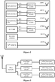
- antennas for different function modules are designed independently at different locations on the terminal, as shown in Figure 1 .
- Multiple antennas may exist in one terminal.
- an LTE mobile phone generally includes a main antenna, a GPS antenna, a BT/WIFI antenna, a diversity antenna, an NFC antenna.
- a multi-mode terminal may include more antennas.
- antennas are arranged on an upper end, a lower end and two sides of the terminal, as shown in Figure 2 .
- performances of the antennas may become poor since strong interference exists between signal transmissions and signal receptions. Therefore, it is difficult to arrange the antennas and give an overall consideration to all the antennas in the limited space inside the terminal, thereby making poor performances of a few of antennas in using the terminal, and affecting user experiences.
- the antennas for the communication modules are integrated into one antenna by directly adding a filter network and a matching circuit in the terminal.
- radio frequency transceiver circuits corresponding to the antennas of the communication modules are needed.
- the filter network passes a received signal or transmitted signal in an operating frequency band of a respective radio frequency transceiver circuit, while isolates received signals or transmitted signals in operating frequency bands of other radio frequency transceiver circuits, and the matching circuit matches impedances of the antennas with impedances of the radio frequency transceiver circuits, as shown in Figure 3 .
- This solution can be only applied in combining multiple frequency bands or simply combining GPS and BT/WIFI but can not achieve a multi-mode multi-pass communication, since the antenna is not separated into a transmission antenna and a reception antenna in this solution.
- WO2012027703 discloses that a transmission signal path and a reception signal path are connected to antennas via tunable power amplifiers and tunable filters and tunable impedance matching networks.
- EP15213798 discloses that an antenna is connected to aninput and output interface via multiple paths.
- WO2009083647 discloses that in many communications systems transmission and reception may also take place at the same time; then typically, a duplex-filter is required for separating reception and transmission signals and also for combining a transmission signal with a reception signal into one antenna feed point. Therefore, it is an urgent issue to be solved that how to reduce interference between multiple antennas and achieve the multi-mode multi-pass communication.
- US2008159363 discloses an antenna system comprising a first antenna, a second antenna, a first feed selection device, and a second feed selection device, wherein the first and second antennas comprise a plurality of feed points, and the selection devices are adapted for connecting the feed points to different communication modules.
- the present disclosure provides an antenna system, an integrated communication structure and a terminal according to the attached independent claims, which can achieve isolation among the multiple antennas and can be applied in a multi-mode terminal. Preferred embodiments are recited in the independent claims.
- the antenna system includes: a first antenna and a second antenna.
- the first antenna is connected to transmission paths of multiple communication modules and is configured to transmit transmission signals from the transmission paths; and the second antenna is connected to reception paths of the multiple communication modules and is configured to transfer signals received from an outside to the communication modules via the reception paths corresponding to the communication modules.
- a transmission function and a reception function of each of the communication modules are separated; hence antennas of the multiple communication modules may be integrated into two antennas, i.e. the first antenna only for a user sending a signal and the second antenna only for the user receiving a signal, thereby effectively reducing the number of antennas and reducing a stacking difficulty.
- the distance between the first antenna and the second antenna is maximized to increase isolation between the antennas, thereby reducing interference between the first antenna and the second antenna.
- the first antenna may be arranged at a lower portion of the terminal and the second antenna may be arranged at an upper portion of the terminal.
- the first antenna and the second antenna each may simultaneously transmit a signal and receive a signal and achieve duplex modes of the modules.
- the multi-mode multi-pass communication can be achieved with fewer components such as duplexer, triplexer and multiplexer, thereby reducing a component cost and an area of a PCB layout.
- the antenna system may further include an interference isolation device, where the interference isolation device is arranged between each of the transmission paths and the first antenna and is configured to isolate interference signals reflected to the transmission paths to which the interference isolation device is connected.
- the interference isolation device is arranged between each of the transmission paths and the first antenna. In this way, a signal can only be transferred from a communication module to the first antenna and be transmitted outwardly via the first antenna, and a signal is prevented from being transferred from the first antenna to the communication module, thereby effectively isolating interference signals reflected to the transmission paths and achieving the stable output of the transmission paths.
- interference isolation device There are many components, circuits or apparatus for achieving the functions of the above interference isolation device.
- an isolator may be chosen.
- the interference isolation device is not limited to the isolator herein.
- the communication module may be connected to a transmission antenna via multiple transmission paths and connected to a reception antenna via multiple reception paths; and a one-to-one correspondence may exist between the communication frequency bands, the transmission paths and the reception paths.
- a transmission path and a reception path are provided for each of the frequency bands, and a one-to-one correspondence exists between the communication frequency bands, the transmission paths and the reception paths. In this way, receptions and transmissions for the respective frequency bands in a single module are completed, thereby achieving a multi-band multi-pass communication in the same module and effectively managing the multiple frequency bands of the same communication module.
- the antenna system may further include: a first frequency band selection device and a second frequency band selection device.
- the first frequency band selection device is connected to multiple transmission paths of the communication module and is configured to select a transmission path from the multiple transmission paths based on a current operating frequency band, to provide a transmission signal to the first antenna via the selected transmission path.
- the second frequency band selection device is connected to multiple reception paths of the communication module and is configured to select a reception path from the multiple reception paths based on the current operating frequency band to transfer a signal received from the second antenna to the communication module via the selected reception path.
- a currently used frequency band may be selected with the first/second frequency band selection device, thereby combining the transmission/reception paths corresponding to the multiple frequency bands and simplifying a line structure.
- multiple transmission feed points may be arranged on the first antenna, and the transmission path may be connected to the first antenna via one of the transmission feed points corresponding to the transmission path; and multiple reception feed points may be arranged on the second antenna, and the reception path may be connected to the second antenna via one of the reception feed points corresponding to the reception path.
- excitations may be performed with the respective feed points to achieve an optimum signal radiation, in a case that different transmission/ reception paths are used to perform communications. Since different feed points are integrated into a single transmission/reception antenna, multiple feed points share an antenna region, thereby optimizing the antenna design. Moreover, locations of the feed points may be adjusted. In this case, a feed point may be selected flexibly in an antenna debugging process, thereby improving flexibility in the antenna debugging.
- the antenna system may further include: a first feed point selection device and a second feed point selection device.
- the first feed selection device is connected to the multiple transmission feed points corresponding to the multiple transmission paths of the communication module and is configured to select a transmission feed point from the multiple transmission feed points based on a current operating frequency band, to connect and match the selected transmission feed point with one of the transmission paths currently being in an operating state.
- the second feed point selection device is connected to the multiple reception feed points corresponding to the multiple reception paths of the communication module and is configured to select a reception feed point from the multiple reception feed points based on the current operating frequency band, to connect and match the selected reception feed point with one of the reception paths currently being in an operating state.
- the first/second feed point selection device is arranged and a feed point is selected based on a currently used communication frequency band, the currently used communication frequency band is matched with the selected feed point, thereby achieving an optimum antenna radiation effect.
- an integrated communication structure is further provided according to the present disclosure.
- the integrated communication structure includes: at least one antenna system according to any one of the above technical solutions and multiple communication modules connected to the at least one antenna system.
- antennas of multiple communication modules may be integrated into two antennas, i.e. a first antenna only for a user sending a signal and a second antenna only for the user receiving a signal, thereby effectively reducing the number of antennas and reducing a stacking difficulty.
- the communication modules connected to the antenna system may include at least one of a wireless mobile communication module, a Global Positioning System module, a Bluetooth module, a Wireless Local Area Network module and a diversity module, or a combination thereof.
- a transmission function and a reception function of a transmission antenna and/or a reception antenna, of any other type of communication module which may be arranged in a terminal may also be separated in the above manner, and the transmission antenna and/or reception antenna of the communication module may be integrated with antennas of other communication modules.
- a signal transmission and a signal reception may be achieved simultaneously, or only the signal transmission or the signal reception may be achieved.
- a signal transmission and a signal reception may be achieved simultaneously in the wireless mobile communication module, and only a signal reception can be achieved in the diversity module (corresponding to a diversity antenna).
- a terminal is further provided according to the present disclosure.
- the terminal includes at least one antenna system according to any one of the above technical solutions, or at least one integrated communication structure according to the above technical solutions.
- the transmission antennas and the reception antennas of all the communication modules in the terminal may be integrated respectively, thereby effectively reducing the number of antennas, decreasing a stacking difficulty, avoiding antenna interference between multiple communication devices and achieving a multi-mode multi-pass communication.
- the embodiments of the present disclosure may be provided as a method, a system or a computer program product. Therefore, the present disclosure may be implemented in a complete hardware manner, a complete software manner or in a software-hardware combined manner. In addition, the present disclosure may be implemented as a computer program product stored in one or more computer usable storage mediums (including but not limited to magnetic disk memory, CD-ROM, optical memory and the like) containing computer usable program codes.
- a computer usable storage mediums including but not limited to magnetic disk memory, CD-ROM, optical memory and the like
- each of flows and/or blocks in the flowcharts and/or block diagrams and a combination of the flows and/or blocks in the flowcharts and/or block diagrams may be implemented with computer program instructions.
- These computer program instructions may be provided to a general-purpose computer, a special-purpose computer, an embedded computer or processors of other programmable data processing apparatuses to form a machine.
- a device is formed with instructions executed by the computer or by the processors of other programmable data processing apparatuses, to realize functions specified by one or more flows of the flowcharts and/or specified by one or more blocks of the block diagrams.
- these computer program codes may be stored in a computer readable memory which can guide the computer or other programmable data processing apparatuses to operate in a specified manner.
- a manufacture including an instruction device is formed by instructions stored in the computer readable memory, and the functions specified by one or more flows of the flowcharts and/or one or more blocks of the block diagrams are realized by the instruction device.
- these computer program codes may be loaded to the computer or other programmable data processing apparatuses, hence a series of operation steps are performed by the computer or other programmable apparatuses as processed by the computer.
- instructions executed by the computer or other programmable apparatuses provides steps for realizing functions specified by one or more flows of the flowchart and/or specified by one or more blocks of the block diagrams.
- Figure 4 shows a schematic structural diagram of an antenna system according to an embodiment of the present disclosure.
- an antenna system 400 includes a first antenna 402 and a second antenna 404.
- the first antenna 402 is connected to multiple transmission paths of multiple communication modules and is configured to transmit transmission signals from the transmission paths.
- the second antenna 404 is connected to reception paths of the multiple communication modules and is configured to transfer signals received from the outside to the communication modules via the reception paths corresponding to the communication modules.
- antennas of the multiple communion modules may be integrated into two antennas, i.e, the first antenna 402 only for a user sending a signal and the second antenna 404 only for the user receiving a signal, thereby effectively reducing the number of antennas and reducing a stacking difficulty.
- the communication modules include a communication module 1, a communication module 2 ... a communication module n.
- the following can be achieved: 1. separating a transmission function and a reception function of each of the communication modules; 2. integrating the transmission functions of the multiple communication modules and integrating the reception functions of the multiple communication modules. Therefore, all of the communication modules can receive and transmit signals only with the first antenna 402 and the second antenna 404.
- the first antenna 402 and the second antenna 404 each may transmit a signal and receive a signal simultaneously and achieve duplex modes of the modules.
- a multi-mode multi-pass communication can be achieved with fewer components such as a duplexer, a triplexer and a multiplexer, thereby reducing a component cost and an area of a PCB layout.
- a signal transmission and a signal reception are generally related to each other, for example, sometimes the both are combined into 'signal transmission-reception'.
- a communication module does not always have a signal transmission function and a signal reception function simultaneously.
- the communication module 1, the communication module 2 and the like may have the signal transmission function and the signal reception function simultaneously and may be provided with transmission paths corresponding to the signal transmission function and reception paths corresponding to the signal reception function.
- the communication module n and the like may only have the signal reception function and may be provided with only a reception path corresponding to the signal reception function; and some communication modules (not shown in the figure 4 ) may only have the signal transmission function and may be provided with only transmission paths corresponding to the signal transmission function.
- connection structure inside a terminal containing the above antenna system is described in detail in conjunction with Figure 5 .
- Figure 5 shows a schematic structural diagram of an antenna design of a multi-mode terminal according to an embodiment of the present disclosure.
- the antenna system shown in Figure 4 is used in a terminal 500.
- 'transmission antenna' corresponds to the first antenna 402 shown in Figure 4
- 'reception antenna' corresponds to the second antenna 404 shown in Figure 4 .
- the terminal 500 shown in Figure 5 contains communication modules such as a main communication module 1, a main communication module 2, a main communication module 3, a WIFI module, a BT (Bluetooth) module, a diversity antenna and a GPS module.
- a main communication module 1 such as a Wi-Fi module
- a main communication module 2 such as a Wi-Fi module
- a main communication module 3 such as a Wi-Fi module
- a BT (Bluetooth) module such as a Wi-Fi Protectet Access (WPA) module
- BT Bluetooth
- the main communication module 1, the main communication module 2 and the main communication module 3 indicates that the terminal 500 may be a three-mode terminal. Further, it may be assumed that the main communication module 1 is a CDMA module, the main communication module 2 is a GSM (or WCDMA) module, and the main communication module 3 is an LTE module.
- the communication module may be connected to the transmission antenna via a transmission path (TX, i.e. Transmission, shown in the figure 5 ) corresponding to the communication module.
- TX transmission path
- the transmission path may be connected to an output end of a power amplifier (PA) in the communication module.
- PA power amplifier
- the communication module may be connected to the reception antenna via a reception path (RX, i.e. Reception, shown in the figure 5 ) corresponding to the communication module.
- the main communication module 1 is connected to a feed point 1 of the transmission antenna
- the main communication module 2 is connected to a feed point 2 of the transmission antenna
- the main communication module 3 is connected to a feed point 3 of the transmission antenna
- the WIFI/BT module is connected to a feed point 4 of the transmission antenna
- the main communication module 1 is connected to a feed point 1' of the reception antenna
- the main communication module 2 is connected to a feed point 2' of the reception antenna
- the main communication module 3 is connected to a feed point 3' of the reception antenna
- the WIFI/BT module is connected to a feed point 4' of the reception antenna
- the diversity antenna is connected to a feed point 5' of the reception antenna
- the GPS module is connected to a feed point 6' of the reception antenna.
- the terminal 500 may further include interference isolation devices arranged between the transmission paths and the first antenna and configured to isolate interference signals reflected to the transmission paths to which the interference isolation devices are connected.
- interference isolation devices arranged between the transmission paths and the first antenna and configured to isolate interference signals reflected to the transmission paths to which the interference isolation devices are connected.
- the interference isolation device is arranged between each of the transmission paths and the first antenna.
- a signal can only be transferred from the communication module to the first antenna and be transmitted outwardly via the first antenna, and a signal is prevented from being transferred from the first antenna to the communication module, thereby effectively isolating interference signals reflected to the transmission paths and achieving the stable output of the transmission paths.
- an isolator may be chosen.
- the main communication module 1, the main communication 2, the main communication 3 and the WIFI/BT module are respectively connected to the feed points on the transmission antenna via isolators.
- the interference isolation device is not limited to the isolator herein.
- Figure 6 shows a schematic diagram of locations where a reception antenna and a transmission antenna are respectively arranged according to an embodiment of the present disclosure.
- the transmission antenna is arranged at a lower portion of the terminal 500, and the reception antenna is arranged on an upper portion of the terminal 500.
- the distance between the transmission antenna and the reception antenna is maximized to increase isolation between the antennas, thereby reducing interference between signals.
- transmission antenna and the reception antenna are not limited to those in the terminal 500.
- the transmission antenna may be arranged at the upper portion of the terminal 500 and the reception antenna may be arranged at the lower portion of the terminal 500.
- Figure 7 shows a schematic diagram of connections of antennas of a multi-band module according to an embodiment of the present disclosure.
- the communication module in a case that a communication module supports multiple communication frequency bands, the communication module is connected to a transmission antenna via multiple transmission paths and is connected to a reception antenna via multiple reception paths.
- the multi-band module is a module 1 in Figure 7 and the module 1 supports communication frequency bands such as a frequency band 1, a frequency band 2 and a frequency band 3.
- the module 1 is connected to a feed point 1, a feed point 2 and a feed point 3 on the transmission antenna via three transmission paths corresponding to the above frequency band 1, frequency band 2 and frequency band 3.
- the module 1 is connected to a feed point 1', a feed point 2' and a feed point 3' on the reception antenna via three reception paths.
- a transmission path and a reception path are provided for each of the frequency bands, and a one-to-one correspondence exists between the communication frequency bands, the transmission paths and the reception paths.
- transmissions and receptions of the respective frequency bands of a single module are completed, thereby achieving a multi-band multi-pass communication in the same module and effectively managing the multiple frequency bands of the same communication module.
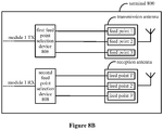
- Figures 8A and 8B show schematic diagrams of connections of antennas of a multi-band module according to another embodiment of the present disclosure.
- the transmission paths and the reception paths of a few of or all of the frequency bands may be combined into one transmission path and one reception path, thereby reducing the number of the transmission/reception paths and simplifying a line structure.
- a module 1 supports a frequency band 1, a frequency band 2, a frequency band 3 and the like in a terminal 800, in order to simplify connection structures of the module 1, the terminal 800 may include: a first frequency band selection device 802 and a second frequency band selection device 804.
- the first frequency band selection device 802 is connected to multiple transmission paths of the module 1 and is configured to select a transmission path from the multiple transmission paths based on a current operating frequency band, to transmit a transmission signal to a transmission antenna (as shown in Figure 8B ) via the selected transmission path; and the second frequency band selection device 804 is connected to multiple reception paths of the module 1 and is configured to select a reception path from the multiple reception paths based on the current operating frequency band, to transfer a signal received from a reception antenna (as shown in Figure 8B ) to the module 1 via the selected reception path.
- a currently used frequency band may be selected with the first frequency band selection device 802 and the second frequency band selection device 804, thereby combining the transmission/reception paths corresponding to the multiple frequency bands and simplifying a line structure.
- multiple transmission feed points i.e. a feed point 1, a feed point 2, a feed point 3
- the transmission paths of the module 1 are connected to the transmission antenna via the transmission feed points corresponding to the transmission paths
- multiple reception feed points i.e. a feed point 1', a feed point 2', a feed point 3'
- the reception paths of the module 1 are connected to the reception antenna via the reception feed points corresponding to the reception paths.
- excitations may be performed with the feed points corresponding to the transmission/reception paths to achieve an optimum signal radiation. Since different feed points are integrated into a single transmission/reception antenna, multiple feed points share an antenna region, thereby optimizing an antenna design. Moreover, locations of the feed points may be adjusted, and hence a feed point may be selected flexibly in an antenna debugging process, thereby improving flexibility in the antenna debugging.
- the terminal 800 may further include a first feed point selection device 806 and a second feed point selection device 808.
- the first feed point selection device 806 is connected to multiple transmission feed points corresponding to the multiple transmission paths of the module 1 and is configured to select a transmission feed point from the multiple feed points based on a current operating frequency band, to connect and match the selected transmission feed point with one of the transmission paths being currently in an operating state.
- the second feed point selection device 808 is connected to multiple reception feed points corresponding to the multiple reception paths of the module 1 and is configured to select a reception feed point from the multiple reception feed points based on the current operating frequency band, to connect and match the selected reception feed point with one of the reception paths being currently in an operating state.
- the first feed point selection device 806 and the second feed point selection device 808 are arranged and a feed point is selected based on the currently used communication frequency band.
- the currently used communication frequency band is matched with the selected feed point, thereby achieving an optimum antenna radiation effect.
- first frequency band selection device 802, the second frequency band selection device 804, the first feed point selection device 806, the second feed point selection device 808 shown in Figures 8A and 8B may be implemented with multiple components, circuits or apparatuses.
- a switch circuit may be used; as another preferable embodiment, a filter may be used.
- the integrated communication structure includes: at least one antenna system according to any one of the above technical solutions and multiple communication modules connected to the at least one antenna system.
- the communication modules connected to the at least one antenna systems may include at least one of a wireless mobile communication module a Global Positioning System module, a Bluetooth module, a Wireless Local Area Network module and a diversity module, or a combination thereof.
- the wireless mobile communication module may be a communication module based on a 2G network such as GSM, may be a communication module based on a 3G network such as WCDMA or CDMA2000, may be a communication module based on a 4G network such as LTE, or may be communication modules based on other network technologies.
- a 2G network such as GSM
- a 3G network such as WCDMA or CDMA2000
- a 4G network such as LTE
- LTE Long Term Evolution
- the present disclosure provides an antenna system, an integrated communication structure and a terminal. Transmission antennas and reception antennas of all communication modules in the terminal may be integrated respectively, thereby effectively reducing the number of antennas, decreasing a stacking difficulty, avoiding antenna interference between multiple communication apparatuses and achieving a multi-mode multi-pass communication.
- the embodiments of the present disclosure may be provided as a method, a system or a computer program product. Therefore, the present disclosure may be implemented in a complete hardware manner, a complete software manner or in a software-hardware combined manner. In addition, the present disclosure may be implemented as a computer program product stored in one or more computer usable storage mediums (including but not limited to magnetic disk memory, CD-ROM, optical memory and the like) containing computer usable program codes.
- a computer usable storage mediums including but not limited to magnetic disk memory, CD-ROM, optical memory and the like
- a device is formed with instructions executed by the computer or by the processors of other programmable data processing apparatuses, which is configured to realize functions specified by one or more flows of the flowcharts and/or specified by one or more blocks of the block diagrams.
- these computer program codes may be stored in a computer readable memory which can guide the computer or other programmable data processing apparatuses to operate in a specified manner.
- a manufacture including an instruction device is formed by instructions stored in the computer readable memory.
- the functions specified by one or more flows of the flowcharts and/or one or more blocks of the block diagrams are realized by the instruction device.
- these computer program codes may be loaded to the computer or other programmable data processing apparatuses, hence a series of operation steps are performed by the computer or other programmable apparatuses as processed by a computer.
- instructions executed by the computer or other programmable apparatuses provide steps for realizing the functions specified by one or more flows of the flowchart and/or specified by one or more blocks of the block diagrams.
Claims (8)
- Système d'antenne, comprenant :une première antenne (402), dans lequel la première antenne (402) est pourvue d'une pluralité de points d'alimentation de transmission, la première antenne (402) est connectée à des chemins de transmission d'une pluralité de modules de communication via la pluralité de points d'alimentation de transmission et est configurée pour transmettre des signaux de transmission à partir des chemins de transmission ;une deuxième antenne (404), dans lequel la deuxième antenne (404) est pourvue d'une pluralité de points d'alimentation de réception, la deuxième antenne (404) est connectée à des chemins de réception de la pluralité de modules de communication via la pluralité de points d'alimentation de réception et est configurée pour transférer des signaux reçus à partir d'un extérieur aux modules de communication via les chemins de réception correspondant aux modules de communication, dans lequel au moins l'un de la pluralité de modules de communication supporte une pluralité de bandes de fréquences de communication,dans lequel la première antenne (402) est connectée à une pluralité de chemins de transmission du au moins un de la pluralité de modules de communication supportant une pluralité de bandes de fréquences de communication via des points d'alimentation de transmission, et la deuxième antenne (404) est connectée à une pluralité de chemins de réception du au moins un de la pluralité de modules de communication supportant une pluralité de bandes de fréquences de communication via des points d'alimentation de réception, etdans lequel la première antenne (402) est connectée au chemin de transmission de chacun des modules de communication ne supportant pas de pluralité de bande de fréquences via un seul point d'alimentation de transmission respectif, et la deuxième antenne (404) est connectée au chemin de réception de chacun des modules de communication ne supportant pas de pluralité de bandes de fréquences de communication via un seul point d'alimentation de réception respectif ;un premier dispositif de sélection de point d'alimentation (806), dans lequel le premier dispositif de sélection de point d'alimentation (806) est connecté aux points d'alimentation de transmission correspondant à la pluralité de chemins de transmission du au moins un de la pluralité de modules de communication supportant une pluralité de bandes de fréquences de communication et est configuré pour sélectionner un point d'alimentation de transmission à partir des points d'alimentation de transmission sur la base d'une bande de fréquences opérationnelle actuelle, pour connecter et faire correspondre le point d'alimentation de transmission sélectionné avec l'un des chemins de transmission actuellement dans un état opérationnel ; etun deuxième dispositif de sélection de point d'alimentation (808), dans lequel le deuxième dispositif de sélection de point d'alimentation (808) est connecté aux points d'alimentation de réception correspondant à la pluralité de chemins de réception du au moins un de la pluralité de modules de communication supportant une pluralité de bandes de fréquences de communication et est configuré pour sélectionner un point d'alimentation de réception à partir des points d'alimentation de réception sur la base de la bande de fréquences opérationnelle actuelle, pour connecter et faire correspondre les point d'alimentation de réception sélectionnés avec l'un des chemins de réception actuellement dans un état opérationnel.
- Système d'antenne selon la revendication 1, comprenant en outre :
un dispositif d'isolation d'interférence, dans lequel le dispositif d'isolation d'interférence est agencé entre chacun des chemins de transmission des modules de communication ne supportant pas de pluralité de bandes de fréquences de communication, et la première antenne (402) et est configuré pour isoler un signal d'interférence réfléchi vers le chemin de transmission auquel est connecté le dispositif d'isolation d'interférence. - Système d'antenne selon la revendication 2, dans lequel le dispositif d'isolation d'interférence comprend un isolateur unidirectionnel.
- Système d'antenne selon la revendication 1, dans lequel
la pluralité de bandes de fréquences de communication, la pluralité de chemins de transmission et la pluralité de chemins de réception du au moins un de la pluralité de modules de communication supportant une pluralité de bandes de fréquences de communication ont une correspondance biunivoque. - Système d'antenne selon la revendication 1, comprenant en outre :un premier dispositif de sélection de bande de fréquences (802), dans lequel le premier dispositif de sélection de bande de fréquences (802) est connecté à la pluralité de chemins de transmission du au moins un de la pluralité de modules de communication supportant une pluralité de bandes de fréquences de communication et est configuré pour sélectionner un chemin de transmission à partir de la pluralité de chemins de transmission sur la base d'une bande de fréquences opérationnelle actuelle, pour fournir un signal de transmission à la première antenne (402) via le chemin de transmission sélectionné ; etun deuxième dispositif de sélection de bande de fréquences (804), dans lequel le deuxième dispositif de sélection de bande de fréquences (804) est connecté à la pluralité de chemins de réception du au moins un de la pluralité de modules de communication supportant une pluralité de bandes de fréquences de communication et est configuré pour sélectionner un chemin de réception à partir de la pluralité de chemins de réception sur la base de la bande de fréquences opérationnelle actuelle pour transférer un signal reçu à partir de la deuxième antenne (404) au module de communication via le chemin de réception sélectionné.
- Système de communication, comprenant au moins un système d'antenne selon l'une quelconque des revendications 1 à 5 et une pluralité de modules de communication connectés au au moins un système d'antenne.
- Système de communication selon la revendication 6, dans lequel les modules de communication connectés au au moins un système d'antenne comprend au moins l'un parmi un module de communication mobile sans fil, un module de système de positionnement global, un module Bluetooth, un module de réseau local sans fil et un module de diversité ; ou une combinaison d'un module de communication mobile sans fil, d'un module de système de positionnement global, d'un module Bluetooth, d'un module de réseau local sans fil et d'un module de diversité.
- Terminal, comprenant au moins un système d'antenne selon l'une quelconque des revendications 1 à 5 ou au moins un système de communication selon la revendication 6 ou 7.
Applications Claiming Priority (1)
| Application Number | Priority Date | Filing Date | Title |
|---|---|---|---|
| PCT/CN2013/090172 WO2015089851A1 (fr) | 2013-12-21 | 2013-12-21 | Système d'antenne, structure de communication intégrée et terminal |
Publications (3)
| Publication Number | Publication Date |
|---|---|
| EP3086477A1 EP3086477A1 (fr) | 2016-10-26 |
| EP3086477A4 EP3086477A4 (fr) | 2017-07-19 |
| EP3086477B1 true EP3086477B1 (fr) | 2020-02-05 |
Family
ID=53402015
Family Applications (1)
| Application Number | Title | Priority Date | Filing Date |
|---|---|---|---|
| EP13899889.3A Active EP3086477B1 (fr) | 2013-12-21 | 2013-12-21 | Système d'antenne, structure de communication intégrée et terminal |
Country Status (4)
| Country | Link |
|---|---|
| US (1) | US9917602B2 (fr) |
| EP (1) | EP3086477B1 (fr) |
| CN (1) | CN104904127A (fr) |
| WO (1) | WO2015089851A1 (fr) |
Families Citing this family (9)
| Publication number | Priority date | Publication date | Assignee | Title |
|---|---|---|---|---|
| US9992775B2 (en) * | 2015-01-30 | 2018-06-05 | Qualcomm Incorporated | Band preference in wireless networks |
| CN106711582A (zh) * | 2016-12-23 | 2017-05-24 | 上海传英信息技术有限公司 | 天线结构及具有该天线结构的移动通信装置 |
| CN109256622A (zh) * | 2017-07-14 | 2019-01-22 | 深圳市杰迅通无线技术有限公司 | 一种集成式天线 |
| US10478561B2 (en) | 2017-08-03 | 2019-11-19 | Minhong Yu | Wireless transmission system with integrated sensing capability |
| CN107835338A (zh) * | 2017-12-01 | 2018-03-23 | 深圳市天鼎微波科技有限公司 | 一种信号传输设备 |
| KR102068569B1 (ko) * | 2018-04-05 | 2020-01-21 | 엘지전자 주식회사 | 이동 단말기 |
| CN111277339B (zh) * | 2018-11-19 | 2022-04-01 | 中国移动通信有限公司研究院 | 一种一体化综合路测仪表 |
| EP3994800A1 (fr) * | 2019-07-04 | 2022-05-11 | Telefonaktiebolaget LM Ericsson (publ) | Configuration inter-antennes dans une radio bibande à duplexage par répartition en fréquence (fdd) |
| CN111162818B (zh) * | 2019-12-31 | 2021-11-23 | 上海微波技术研究所(中国电子科技集团公司第五十研究所) | 适用于超短波电台在tdma网络下的天线共用器 |
Family Cites Families (21)
| Publication number | Priority date | Publication date | Assignee | Title |
|---|---|---|---|---|
| US6381471B1 (en) * | 1999-06-30 | 2002-04-30 | Vladimir A. Dvorkin | Dual band radio telephone with dedicated receive and transmit antennas |
| US7248839B2 (en) * | 2000-06-09 | 2007-07-24 | Daimlerchrysler Ag | Arrangement for operating various terminal devices |
| DE10052711A1 (de) * | 2000-10-24 | 2002-05-02 | Siemens Ag | Multiband-Endgerät |
| DE10345971B4 (de) * | 2003-10-02 | 2005-12-22 | Siemens Ag | Mobilfunk-Sendeempfangseinrichtung |
| WO2008073372A2 (fr) * | 2006-12-11 | 2008-06-19 | Qualcomm Incorporated | Dispositif à antennes multiples pourvu d'un élément d'isolation |
| US7839334B2 (en) | 2006-12-29 | 2010-11-23 | Broadcom Corporation | IC with a 55-64 GHz antenna |
| FI20075974A0 (fi) * | 2007-12-28 | 2007-12-28 | Nokia Corp | Laite ja menetelmä |
| US8467738B2 (en) * | 2009-05-04 | 2013-06-18 | Rfaxis, Inc. | Multi-mode radio frequency front end module |
| CN101771455A (zh) * | 2010-01-08 | 2010-07-07 | 北京交通大学 | 一种采用双天线分集接收技术的gsm-r通信模块 |
| CN103155431B (zh) * | 2010-08-26 | 2015-08-19 | 维斯普瑞公司 | 可调无线电前端及方法 |
| US8723733B2 (en) * | 2010-09-29 | 2014-05-13 | Qualcomm Incorporated | Multiband antenna for a mobile device |
| US8509718B2 (en) * | 2010-10-13 | 2013-08-13 | Rf Micro Devices, Inc. | Broadband receive only tuner combined with receive switch |
| US8588687B2 (en) * | 2010-10-15 | 2013-11-19 | Roche Diagnostics Operations, Inc. | Coexistence of multiple radios in a medical device |
| CN102111177A (zh) * | 2010-12-24 | 2011-06-29 | 重庆大学 | 一种双天线全双工软件无线电收发机 |
| CN102064845A (zh) * | 2010-12-28 | 2011-05-18 | 惠州Tcl移动通信有限公司 | 共用天线的无线通信设备及采用所述设备的通信方法 |
| US8942644B2 (en) * | 2011-11-11 | 2015-01-27 | Apple Inc. | Systems and methods for protecting microelectromechanical systems switches from radio-frequency signals using switching circuitry |
| US8874047B2 (en) * | 2012-03-19 | 2014-10-28 | Intel Mobile Communications GmbH | Agile and adaptive transmitter-receiver isolation |
| TW201342823A (zh) * | 2012-04-09 | 2013-10-16 | Asustek Comp Inc | 擴充裝置 |
| EP2940907B1 (fr) | 2012-12-26 | 2018-09-05 | Huawei Technologies Co., Ltd. | Système d'antenne |
| CN203180917U (zh) * | 2013-02-26 | 2013-09-04 | 步步高通信科技有限公司 | 一种收发通道独立的射频前端 |
| US9214981B1 (en) * | 2013-12-02 | 2015-12-15 | Sprint Communications Company L.P. | Configurable antenna port selection for beam forming and MIMO in a telecommunications network |
-
2013
- 2013-12-21 WO PCT/CN2013/090172 patent/WO2015089851A1/fr active Application Filing
- 2013-12-21 US US15/034,639 patent/US9917602B2/en active Active
- 2013-12-21 EP EP13899889.3A patent/EP3086477B1/fr active Active
- 2013-12-21 CN CN201380068916.4A patent/CN104904127A/zh active Pending
Non-Patent Citations (1)
| Title |
|---|
| None * |
Also Published As
| Publication number | Publication date |
|---|---|
| CN104904127A (zh) | 2015-09-09 |
| EP3086477A4 (fr) | 2017-07-19 |
| US20160277042A1 (en) | 2016-09-22 |
| EP3086477A1 (fr) | 2016-10-26 |
| WO2015089851A1 (fr) | 2015-06-25 |
| US9917602B2 (en) | 2018-03-13 |
Similar Documents
| Publication | Publication Date | Title |
|---|---|---|
| EP3086477B1 (fr) | Système d'antenne, structure de communication intégrée et terminal | |
| CN113746496B (zh) | 射频系统及电子设备 | |
| US9859943B2 (en) | Tunable RF diplexer | |
| US7872547B2 (en) | Wireless communication device | |
| EP2911305B1 (fr) | Multiplexeur | |
| US20130051284A1 (en) | Carrier aggregation radio system | |
| US9130604B2 (en) | Multi-band multi-path receiving and transmitting device and method, and base station system | |
| US11223384B2 (en) | Low noise signal chain architecture | |
| EP3116133B1 (fr) | Terminal multimode à double trajet | |
| US8432836B2 (en) | Wireless circuitry with simultaneous voice and data capabilities and reduced intermodulation distortion | |
| TW201740701A (zh) | 具有可切換雙工器的前端架構 | |
| US20190196555A1 (en) | Multiple donor antenna repeater | |
| KR20130074585A (ko) | 고주파 수동 소자를 이용한 rf 송수신기의 전치단 장치 | |
| CN109983713A (zh) | 用于增强邻接波段中的信号的信号增强器 | |
| WO2020068451A1 (fr) | Dispositif de communication sans fil | |
| EP4274105A1 (fr) | Circuit radiofréquence et dispositif électronique | |
| JP6174167B2 (ja) | 無線通信ネットワークにおける無線接続ノードシステムのアンテナ共用化装置 | |
| CN107800459B (zh) | 用于跨频段载波聚合的射频拉远单元rru及合路方法 | |
| CA3080970A1 (fr) | Suramplificateur multiutilisateur | |
| JP2016127487A (ja) | 無線通信装置及びアンテナ共用方法 | |
| Liu et al. | A new architecture design for WCDMA and GSM dual-mode mobile phones | |
| EP2980997A1 (fr) | Système de communication sans fil |
Legal Events
| Date | Code | Title | Description |
|---|---|---|---|
| PUAI | Public reference made under article 153(3) epc to a published international application that has entered the european phase |
Free format text: ORIGINAL CODE: 0009012 |
|
| 17P | Request for examination filed |
Effective date: 20160511 |
|
| AK | Designated contracting states |
Kind code of ref document: A1 Designated state(s): AL AT BE BG CH CY CZ DE DK EE ES FI FR GB GR HR HU IE IS IT LI LT LU LV MC MK MT NL NO PL PT RO RS SE SI SK SM TR |
|
| AX | Request for extension of the european patent |
Extension state: BA ME |
|
| DAX | Request for extension of the european patent (deleted) | ||
| A4 | Supplementary search report drawn up and despatched |
Effective date: 20170621 |
|
| RIC1 | Information provided on ipc code assigned before grant |
Ipc: H04B 1/38 20150101AFI20170614BHEP |
|
| STAA | Information on the status of an ep patent application or granted ep patent |
Free format text: STATUS: EXAMINATION IS IN PROGRESS |
|
| 17Q | First examination report despatched |
Effective date: 20180530 |
|
| GRAP | Despatch of communication of intention to grant a patent |
Free format text: ORIGINAL CODE: EPIDOSNIGR1 |
|
| STAA | Information on the status of an ep patent application or granted ep patent |
Free format text: STATUS: GRANT OF PATENT IS INTENDED |
|
| INTG | Intention to grant announced |
Effective date: 20190716 |
|
| GRAS | Grant fee paid |
Free format text: ORIGINAL CODE: EPIDOSNIGR3 |
|
| GRAA | (expected) grant |
Free format text: ORIGINAL CODE: 0009210 |
|
| STAA | Information on the status of an ep patent application or granted ep patent |
Free format text: STATUS: THE PATENT HAS BEEN GRANTED |
|
| AK | Designated contracting states |
Kind code of ref document: B1 Designated state(s): AL AT BE BG CH CY CZ DE DK EE ES FI FR GB GR HR HU IE IS IT LI LT LU LV MC MK MT NL NO PL PT RO RS SE SI SK SM TR |
|
| REG | Reference to a national code |
Ref country code: GB Ref legal event code: FG4D |
|
| REG | Reference to a national code |
Ref country code: AT Ref legal event code: REF Ref document number: 1230586 Country of ref document: AT Kind code of ref document: T Effective date: 20200215 |
|
| REG | Reference to a national code |
Ref country code: DE Ref legal event code: R096 Ref document number: 602013065590 Country of ref document: DE |
|
| REG | Reference to a national code |
Ref country code: IE Ref legal event code: FG4D |
|
| REG | Reference to a national code |
Ref country code: CH Ref legal event code: EP |
|
| REG | Reference to a national code |
Ref country code: NL Ref legal event code: FP |
|
| PG25 | Lapsed in a contracting state [announced via postgrant information from national office to epo] |
Ref country code: FI Free format text: LAPSE BECAUSE OF FAILURE TO SUBMIT A TRANSLATION OF THE DESCRIPTION OR TO PAY THE FEE WITHIN THE PRESCRIBED TIME-LIMIT Effective date: 20200205 Ref country code: RS Free format text: LAPSE BECAUSE OF FAILURE TO SUBMIT A TRANSLATION OF THE DESCRIPTION OR TO PAY THE FEE WITHIN THE PRESCRIBED TIME-LIMIT Effective date: 20200205 Ref country code: NO Free format text: LAPSE BECAUSE OF FAILURE TO SUBMIT A TRANSLATION OF THE DESCRIPTION OR TO PAY THE FEE WITHIN THE PRESCRIBED TIME-LIMIT Effective date: 20200505 Ref country code: PT Free format text: LAPSE BECAUSE OF FAILURE TO SUBMIT A TRANSLATION OF THE DESCRIPTION OR TO PAY THE FEE WITHIN THE PRESCRIBED TIME-LIMIT Effective date: 20200628 |
|
| REG | Reference to a national code |
Ref country code: LT Ref legal event code: MG4D |
|
| PG25 | Lapsed in a contracting state [announced via postgrant information from national office to epo] |
Ref country code: BG Free format text: LAPSE BECAUSE OF FAILURE TO SUBMIT A TRANSLATION OF THE DESCRIPTION OR TO PAY THE FEE WITHIN THE PRESCRIBED TIME-LIMIT Effective date: 20200505 Ref country code: LV Free format text: LAPSE BECAUSE OF FAILURE TO SUBMIT A TRANSLATION OF THE DESCRIPTION OR TO PAY THE FEE WITHIN THE PRESCRIBED TIME-LIMIT Effective date: 20200205 Ref country code: SE Free format text: LAPSE BECAUSE OF FAILURE TO SUBMIT A TRANSLATION OF THE DESCRIPTION OR TO PAY THE FEE WITHIN THE PRESCRIBED TIME-LIMIT Effective date: 20200205 Ref country code: HR Free format text: LAPSE BECAUSE OF FAILURE TO SUBMIT A TRANSLATION OF THE DESCRIPTION OR TO PAY THE FEE WITHIN THE PRESCRIBED TIME-LIMIT Effective date: 20200205 Ref country code: GR Free format text: LAPSE BECAUSE OF FAILURE TO SUBMIT A TRANSLATION OF THE DESCRIPTION OR TO PAY THE FEE WITHIN THE PRESCRIBED TIME-LIMIT Effective date: 20200506 Ref country code: IS Free format text: LAPSE BECAUSE OF FAILURE TO SUBMIT A TRANSLATION OF THE DESCRIPTION OR TO PAY THE FEE WITHIN THE PRESCRIBED TIME-LIMIT Effective date: 20200605 |
|
| PG25 | Lapsed in a contracting state [announced via postgrant information from national office to epo] |
Ref country code: SK Free format text: LAPSE BECAUSE OF FAILURE TO SUBMIT A TRANSLATION OF THE DESCRIPTION OR TO PAY THE FEE WITHIN THE PRESCRIBED TIME-LIMIT Effective date: 20200205 Ref country code: CZ Free format text: LAPSE BECAUSE OF FAILURE TO SUBMIT A TRANSLATION OF THE DESCRIPTION OR TO PAY THE FEE WITHIN THE PRESCRIBED TIME-LIMIT Effective date: 20200205 Ref country code: RO Free format text: LAPSE BECAUSE OF FAILURE TO SUBMIT A TRANSLATION OF THE DESCRIPTION OR TO PAY THE FEE WITHIN THE PRESCRIBED TIME-LIMIT Effective date: 20200205 Ref country code: EE Free format text: LAPSE BECAUSE OF FAILURE TO SUBMIT A TRANSLATION OF THE DESCRIPTION OR TO PAY THE FEE WITHIN THE PRESCRIBED TIME-LIMIT Effective date: 20200205 Ref country code: SM Free format text: LAPSE BECAUSE OF FAILURE TO SUBMIT A TRANSLATION OF THE DESCRIPTION OR TO PAY THE FEE WITHIN THE PRESCRIBED TIME-LIMIT Effective date: 20200205 Ref country code: DK Free format text: LAPSE BECAUSE OF FAILURE TO SUBMIT A TRANSLATION OF THE DESCRIPTION OR TO PAY THE FEE WITHIN THE PRESCRIBED TIME-LIMIT Effective date: 20200205 Ref country code: LT Free format text: LAPSE BECAUSE OF FAILURE TO SUBMIT A TRANSLATION OF THE DESCRIPTION OR TO PAY THE FEE WITHIN THE PRESCRIBED TIME-LIMIT Effective date: 20200205 Ref country code: ES Free format text: LAPSE BECAUSE OF FAILURE TO SUBMIT A TRANSLATION OF THE DESCRIPTION OR TO PAY THE FEE WITHIN THE PRESCRIBED TIME-LIMIT Effective date: 20200205 |
|
| REG | Reference to a national code |
Ref country code: DE Ref legal event code: R097 Ref document number: 602013065590 Country of ref document: DE |
|
| REG | Reference to a national code |
Ref country code: AT Ref legal event code: MK05 Ref document number: 1230586 Country of ref document: AT Kind code of ref document: T Effective date: 20200205 |
|
| PLBE | No opposition filed within time limit |
Free format text: ORIGINAL CODE: 0009261 |
|
| STAA | Information on the status of an ep patent application or granted ep patent |
Free format text: STATUS: NO OPPOSITION FILED WITHIN TIME LIMIT |
|
| 26N | No opposition filed |
Effective date: 20201106 |
|
| PG25 | Lapsed in a contracting state [announced via postgrant information from national office to epo] |
Ref country code: AT Free format text: LAPSE BECAUSE OF FAILURE TO SUBMIT A TRANSLATION OF THE DESCRIPTION OR TO PAY THE FEE WITHIN THE PRESCRIBED TIME-LIMIT Effective date: 20200205 Ref country code: IT Free format text: LAPSE BECAUSE OF FAILURE TO SUBMIT A TRANSLATION OF THE DESCRIPTION OR TO PAY THE FEE WITHIN THE PRESCRIBED TIME-LIMIT Effective date: 20200205 |
|
| PG25 | Lapsed in a contracting state [announced via postgrant information from national office to epo] |
Ref country code: SI Free format text: LAPSE BECAUSE OF FAILURE TO SUBMIT A TRANSLATION OF THE DESCRIPTION OR TO PAY THE FEE WITHIN THE PRESCRIBED TIME-LIMIT Effective date: 20200205 Ref country code: PL Free format text: LAPSE BECAUSE OF FAILURE TO SUBMIT A TRANSLATION OF THE DESCRIPTION OR TO PAY THE FEE WITHIN THE PRESCRIBED TIME-LIMIT Effective date: 20200205 |
|
| REG | Reference to a national code |
Ref country code: CH Ref legal event code: PL |
|
| PG25 | Lapsed in a contracting state [announced via postgrant information from national office to epo] |
Ref country code: MC Free format text: LAPSE BECAUSE OF FAILURE TO SUBMIT A TRANSLATION OF THE DESCRIPTION OR TO PAY THE FEE WITHIN THE PRESCRIBED TIME-LIMIT Effective date: 20200205 |
|
| REG | Reference to a national code |
Ref country code: BE Ref legal event code: MM Effective date: 20201231 |
|
| PG25 | Lapsed in a contracting state [announced via postgrant information from national office to epo] |
Ref country code: LU Free format text: LAPSE BECAUSE OF NON-PAYMENT OF DUE FEES Effective date: 20201221 Ref country code: IE Free format text: LAPSE BECAUSE OF NON-PAYMENT OF DUE FEES Effective date: 20201221 |
|
| PG25 | Lapsed in a contracting state [announced via postgrant information from national office to epo] |
Ref country code: LI Free format text: LAPSE BECAUSE OF NON-PAYMENT OF DUE FEES Effective date: 20201231 Ref country code: CH Free format text: LAPSE BECAUSE OF NON-PAYMENT OF DUE FEES Effective date: 20201231 |
|
| PG25 | Lapsed in a contracting state [announced via postgrant information from national office to epo] |
Ref country code: TR Free format text: LAPSE BECAUSE OF FAILURE TO SUBMIT A TRANSLATION OF THE DESCRIPTION OR TO PAY THE FEE WITHIN THE PRESCRIBED TIME-LIMIT Effective date: 20200205 Ref country code: MT Free format text: LAPSE BECAUSE OF FAILURE TO SUBMIT A TRANSLATION OF THE DESCRIPTION OR TO PAY THE FEE WITHIN THE PRESCRIBED TIME-LIMIT Effective date: 20200205 Ref country code: CY Free format text: LAPSE BECAUSE OF FAILURE TO SUBMIT A TRANSLATION OF THE DESCRIPTION OR TO PAY THE FEE WITHIN THE PRESCRIBED TIME-LIMIT Effective date: 20200205 |
|
| PG25 | Lapsed in a contracting state [announced via postgrant information from national office to epo] |
Ref country code: MK Free format text: LAPSE BECAUSE OF FAILURE TO SUBMIT A TRANSLATION OF THE DESCRIPTION OR TO PAY THE FEE WITHIN THE PRESCRIBED TIME-LIMIT Effective date: 20200205 Ref country code: AL Free format text: LAPSE BECAUSE OF FAILURE TO SUBMIT A TRANSLATION OF THE DESCRIPTION OR TO PAY THE FEE WITHIN THE PRESCRIBED TIME-LIMIT Effective date: 20200205 |
|
| PG25 | Lapsed in a contracting state [announced via postgrant information from national office to epo] |
Ref country code: BE Free format text: LAPSE BECAUSE OF NON-PAYMENT OF DUE FEES Effective date: 20201231 |
|
| PGFP | Annual fee paid to national office [announced via postgrant information from national office to epo] |
Ref country code: NL Payment date: 20231124 Year of fee payment: 11 |
|
| PGFP | Annual fee paid to national office [announced via postgrant information from national office to epo] |
Ref country code: GB Payment date: 20231221 Year of fee payment: 11 |
|
| PGFP | Annual fee paid to national office [announced via postgrant information from national office to epo] |
Ref country code: FR Payment date: 20231220 Year of fee payment: 11 Ref country code: DE Payment date: 20231208 Year of fee payment: 11 |