EP2980974A1 - Verfahren und Vorrichtung zur Stromregelung eines mehrphasigen verschachtelten Wandlers - Google Patents
Verfahren und Vorrichtung zur Stromregelung eines mehrphasigen verschachtelten Wandlers Download PDFInfo
- Publication number
- EP2980974A1 EP2980974A1 EP14196269.6A EP14196269A EP2980974A1 EP 2980974 A1 EP2980974 A1 EP 2980974A1 EP 14196269 A EP14196269 A EP 14196269A EP 2980974 A1 EP2980974 A1 EP 2980974A1
- Authority
- EP
- European Patent Office
- Prior art keywords
- phase
- phases
- controller
- respective phases
- filter
- Prior art date
- Legal status (The legal status is an assumption and is not a legal conclusion. Google has not performed a legal analysis and makes no representation as to the accuracy of the status listed.)
- Granted
Links
Images



Classifications
-
- H—ELECTRICITY
- H02—GENERATION; CONVERSION OR DISTRIBUTION OF ELECTRIC POWER
- H02M—APPARATUS FOR CONVERSION BETWEEN AC AND AC, BETWEEN AC AND DC, OR BETWEEN DC AND DC, AND FOR USE WITH MAINS OR SIMILAR POWER SUPPLY SYSTEMS; CONVERSION OF DC OR AC INPUT POWER INTO SURGE OUTPUT POWER; CONTROL OR REGULATION THEREOF
- H02M3/00—Conversion of DC power input into DC power output
- H02M3/02—Conversion of DC power input into DC power output without intermediate conversion into AC
- H02M3/04—Conversion of DC power input into DC power output without intermediate conversion into AC by static converters
- H02M3/10—Conversion of DC power input into DC power output without intermediate conversion into AC by static converters using discharge tubes with control electrode or semiconductor devices with control electrode
- H02M3/145—Conversion of DC power input into DC power output without intermediate conversion into AC by static converters using discharge tubes with control electrode or semiconductor devices with control electrode using devices of a triode or transistor type requiring continuous application of a control signal
- H02M3/155—Conversion of DC power input into DC power output without intermediate conversion into AC by static converters using discharge tubes with control electrode or semiconductor devices with control electrode using devices of a triode or transistor type requiring continuous application of a control signal using semiconductor devices only
- H02M3/156—Conversion of DC power input into DC power output without intermediate conversion into AC by static converters using discharge tubes with control electrode or semiconductor devices with control electrode using devices of a triode or transistor type requiring continuous application of a control signal using semiconductor devices only with automatic control of output voltage or current, e.g. switching regulators
- H02M3/158—Conversion of DC power input into DC power output without intermediate conversion into AC by static converters using discharge tubes with control electrode or semiconductor devices with control electrode using devices of a triode or transistor type requiring continuous application of a control signal using semiconductor devices only with automatic control of output voltage or current, e.g. switching regulators including plural semiconductor devices as final control devices for a single load
- H02M3/1584—Conversion of DC power input into DC power output without intermediate conversion into AC by static converters using discharge tubes with control electrode or semiconductor devices with control electrode using devices of a triode or transistor type requiring continuous application of a control signal using semiconductor devices only with automatic control of output voltage or current, e.g. switching regulators including plural semiconductor devices as final control devices for a single load with a plurality of power processing stages connected in parallel
-
- H—ELECTRICITY
- H02—GENERATION; CONVERSION OR DISTRIBUTION OF ELECTRIC POWER
- H02M—APPARATUS FOR CONVERSION BETWEEN AC AND AC, BETWEEN AC AND DC, OR BETWEEN DC AND DC, AND FOR USE WITH MAINS OR SIMILAR POWER SUPPLY SYSTEMS; CONVERSION OF DC OR AC INPUT POWER INTO SURGE OUTPUT POWER; CONTROL OR REGULATION THEREOF
- H02M3/00—Conversion of DC power input into DC power output
- H02M3/02—Conversion of DC power input into DC power output without intermediate conversion into AC
- H02M3/04—Conversion of DC power input into DC power output without intermediate conversion into AC by static converters
- H02M3/10—Conversion of DC power input into DC power output without intermediate conversion into AC by static converters using discharge tubes with control electrode or semiconductor devices with control electrode
- H02M3/145—Conversion of DC power input into DC power output without intermediate conversion into AC by static converters using discharge tubes with control electrode or semiconductor devices with control electrode using devices of a triode or transistor type requiring continuous application of a control signal
- H02M3/155—Conversion of DC power input into DC power output without intermediate conversion into AC by static converters using discharge tubes with control electrode or semiconductor devices with control electrode using devices of a triode or transistor type requiring continuous application of a control signal using semiconductor devices only
- H02M3/156—Conversion of DC power input into DC power output without intermediate conversion into AC by static converters using discharge tubes with control electrode or semiconductor devices with control electrode using devices of a triode or transistor type requiring continuous application of a control signal using semiconductor devices only with automatic control of output voltage or current, e.g. switching regulators
- H02M3/158—Conversion of DC power input into DC power output without intermediate conversion into AC by static converters using discharge tubes with control electrode or semiconductor devices with control electrode using devices of a triode or transistor type requiring continuous application of a control signal using semiconductor devices only with automatic control of output voltage or current, e.g. switching regulators including plural semiconductor devices as final control devices for a single load
-
- H—ELECTRICITY
- H02—GENERATION; CONVERSION OR DISTRIBUTION OF ELECTRIC POWER
- H02M—APPARATUS FOR CONVERSION BETWEEN AC AND AC, BETWEEN AC AND DC, OR BETWEEN DC AND DC, AND FOR USE WITH MAINS OR SIMILAR POWER SUPPLY SYSTEMS; CONVERSION OF DC OR AC INPUT POWER INTO SURGE OUTPUT POWER; CONTROL OR REGULATION THEREOF
- H02M3/00—Conversion of DC power input into DC power output
- H02M3/02—Conversion of DC power input into DC power output without intermediate conversion into AC
- H02M3/04—Conversion of DC power input into DC power output without intermediate conversion into AC by static converters
- H02M3/10—Conversion of DC power input into DC power output without intermediate conversion into AC by static converters using discharge tubes with control electrode or semiconductor devices with control electrode
- H02M3/145—Conversion of DC power input into DC power output without intermediate conversion into AC by static converters using discharge tubes with control electrode or semiconductor devices with control electrode using devices of a triode or transistor type requiring continuous application of a control signal
- H02M3/155—Conversion of DC power input into DC power output without intermediate conversion into AC by static converters using discharge tubes with control electrode or semiconductor devices with control electrode using devices of a triode or transistor type requiring continuous application of a control signal using semiconductor devices only
- H02M3/156—Conversion of DC power input into DC power output without intermediate conversion into AC by static converters using discharge tubes with control electrode or semiconductor devices with control electrode using devices of a triode or transistor type requiring continuous application of a control signal using semiconductor devices only with automatic control of output voltage or current, e.g. switching regulators
-
- H—ELECTRICITY
- H02—GENERATION; CONVERSION OR DISTRIBUTION OF ELECTRIC POWER
- H02M—APPARATUS FOR CONVERSION BETWEEN AC AND AC, BETWEEN AC AND DC, OR BETWEEN DC AND DC, AND FOR USE WITH MAINS OR SIMILAR POWER SUPPLY SYSTEMS; CONVERSION OF DC OR AC INPUT POWER INTO SURGE OUTPUT POWER; CONTROL OR REGULATION THEREOF
- H02M3/00—Conversion of DC power input into DC power output
- H02M3/02—Conversion of DC power input into DC power output without intermediate conversion into AC
- H02M3/04—Conversion of DC power input into DC power output without intermediate conversion into AC by static converters
- H02M3/10—Conversion of DC power input into DC power output without intermediate conversion into AC by static converters using discharge tubes with control electrode or semiconductor devices with control electrode
- H02M3/145—Conversion of DC power input into DC power output without intermediate conversion into AC by static converters using discharge tubes with control electrode or semiconductor devices with control electrode using devices of a triode or transistor type requiring continuous application of a control signal
- H02M3/155—Conversion of DC power input into DC power output without intermediate conversion into AC by static converters using discharge tubes with control electrode or semiconductor devices with control electrode using devices of a triode or transistor type requiring continuous application of a control signal using semiconductor devices only
- H02M3/156—Conversion of DC power input into DC power output without intermediate conversion into AC by static converters using discharge tubes with control electrode or semiconductor devices with control electrode using devices of a triode or transistor type requiring continuous application of a control signal using semiconductor devices only with automatic control of output voltage or current, e.g. switching regulators
- H02M3/158—Conversion of DC power input into DC power output without intermediate conversion into AC by static converters using discharge tubes with control electrode or semiconductor devices with control electrode using devices of a triode or transistor type requiring continuous application of a control signal using semiconductor devices only with automatic control of output voltage or current, e.g. switching regulators including plural semiconductor devices as final control devices for a single load
- H02M3/1584—Conversion of DC power input into DC power output without intermediate conversion into AC by static converters using discharge tubes with control electrode or semiconductor devices with control electrode using devices of a triode or transistor type requiring continuous application of a control signal using semiconductor devices only with automatic control of output voltage or current, e.g. switching regulators including plural semiconductor devices as final control devices for a single load with a plurality of power processing stages connected in parallel
- H02M3/1586—Conversion of DC power input into DC power output without intermediate conversion into AC by static converters using discharge tubes with control electrode or semiconductor devices with control electrode using devices of a triode or transistor type requiring continuous application of a control signal using semiconductor devices only with automatic control of output voltage or current, e.g. switching regulators including plural semiconductor devices as final control devices for a single load with a plurality of power processing stages connected in parallel switched with a phase shift, i.e. interleaved
Definitions
- the present invention relates to a method and apparatus for controlling a current of a multi-phase interleaved converter and, more particularly, to a method and apparatus for controlling a current of a multi-phase interleaved converter to reduce load on a Micro Controller Unit (MCU) () and redress a current imbalance of a multi-phase interleaved converter.
- MCU Micro Controller Unit
- DC/DC converters are applied to various electric power converters such as vehicle battery chargers.
- a ripple current may occur in the inductor of the converter.
- Such a ripple current affects the size constraints of elements such as inductors and capacitors, and is closely related with an amount of power loss.
- Interleaving refers to a method in which the mix of currents flowing with different phases causes their ripple currents to be offset by one another, to cause the combined ripple current to decrease in magnitude by 1/N times whereas the frequency increases by N times; where N denotes the number of phases.
- An interleaved converter connects multiple DC/DC converters in parallel to disperse electric current and uses the phase difference of switching elements to reduce the magnitude and ripple of currents flowing through elements such as inductors.
- the converter may disperse electric current and allow an appropriate level of phase difference for the current, to significantly decrease the ripple of input and output currents.
- the use of such an interleaved converter may increase energy efficiency and adjust the size of elements in the circuit.
- An interleaved converter generally has a structure similar to a parallel connection of multiple single-phase converters. For example, in a three-phase interleaved converter, each switch operates with a phase difference of 120 degrees.
- An N-phase interleaved converter has the same structure as the parallel connection of N single-phase converters, in which each switch operates with a phase difference of (2 ⁇ /N(rad). In an interleaved converter, an increase in the number of phases may require an increase in the number of elements needed in the circuit.
- An object of the present invention is to provide a method and an apparatus for controlling a current of a multi-phase interleaved converter to reflect changes in currents flowing through respective phases to generate more precise duty ratios that correspond to respective phases to adjust currents of respective phases in a balanced way.
- a method of controlling a current of a multi-phase interleaved converter may include: operating, by a controller, a filter, to filter currents flowing into converters of respective phases in a multi-phase interleaved converter having multiple phases; receiving, by the controller, values of the filtered currents for respective phases and a duty ratio for any one of the multiple phase generated in response to a current flowing into the phase; and adjusting, by the controller, duty ratios for phases other than the phase based on the received current values for respective phases.
- the filtering may include smoothing into direct current values currents flowing into converters of respective phases in the multi-phase interleaved converter and flowing through inductors included in each of the converters.
- the filtering may be performed by a filter having a time constant greater than a predetermined reference value.
- the duty ratio for the phase may be generated during a first cycle.
- the adjustment of the duty ratios may be performed during a second cycle.
- the duty ratio for the phase may be generated during a first cycle and the adjustment of the duty ratios may be performed during a second cycle.
- the second cycle may be longer than the first cycle.
- the adjustment of the duty ratios may include reducing the duty ratios for a greater received current value by comparing the received current values for respective phases.
- the adjustment of the duty ratios may also include adjusting the received current values for respective phases and duty ratios for phases other than the phase based on a phase difference between the phases.
- the method may further include adjusting switching of the converters based on the adjusted duty ratios.
- An apparatus for controlling a current of a multi-phase interleaved converter may include: a filter configured to filter currents flowing into converters of respective phases in a multi-phase interleaved converter having multiple phases; and an interleave controller having a current controller configured to sense a current flowing into any one of the multiple phases to generate a duty ratio for a phase that correspond to the current, and a balancing controller configured to receive values of currents for respective phases, filtered by the filter, and a duty ratio generated by the current controller to adjust duty ratios for phases other than the phase based on the received current values for respective phases.
- the filter may be configured to smooth, into direct current values, currents that correspond to respective phases received by the filter.
- the time constant of the filter may be greater than a predetermined reference value.
- the current controller may be configured to generate a duty ratio for the phase during a first cycle.
- the balancing controller may be configured to adjust duty ratios for phases other than the phase during a second cycle.
- the current controller may be configured to generate a duty ratio for the phase during a first cycle
- the balancing controller may be configured to adjust duty ratios for phases other than the phase during a second cycle.
- the second cycle may be longer than the first cycle.
- the balancing controller may be configured to reduce a duty ratio for a greater received current value by comparing the received current values for respective phases.
- the apparatus may further include a phase shifter configured to apply a phase difference between the phases to duty ratios adjusted by the balancing controller and transmit the duty ratios with the phase difference applied to the converters for respective phases.
- vehicle or “vehicular” or other similar term as used herein is inclusive of motor vehicles in general such as passenger automobiles including sports utility vehicles (SUV), buses, trucks, various commercial vehicles, watercraft including a variety of boats and ships, aircraft, and the like, and includes hybrid vehicles, electric vehicles, plug-in hybrid electric vehicles, hydrogen-powered vehicles and other alternative fuel vehicles (e.g. fuels derived from resources other than petroleum).
- a hybrid vehicle is a vehicle that has two or more sources of power, for example both gasoline-powered and electric-powered vehicles.
- controller/control unit refers to a hardware device that includes a memory and a processor.
- the memory is configured to store the modules and the processor is specifically configured to execute said modules to perform one or more processes which are described further below.
- control logic of the present invention may be embodied as non-transitory computer readable media on a computer readable medium containing executable program instructions executed by a processor, controller/control unit or the like.
- the computer readable mediums include, but are not limited to, ROM, RAM, compact disc (CD)-ROMs, magnetic tapes, floppy disks, flash drives, smart cards and optical data storage devices.
- the computer readable recording medium can also be distributed in network coupled computer systems so that the computer readable media is stored and executed in a distributed fashion, e.g., by a telematics server or a Controller Area Network (CAN).
- a telematics server or a Controller Area Network (CAN).
- CAN Controller Area Network
- FIG. 1A through FIG. 2C are exemplary diagrams for existing methods of controlling a current of a multi-phase interleaved converter.
- an output from an input voltage source (Vin) 10 is converted using a three-phase interleaved converter, and a controller (MCU) 20 operating converters 30, 40 and 50 in charge of respective phases (phase A, phase B and phase C) is equipped with current controllers 35, 45 and 55 for the converters 30, 40 and 50, respectively.
- the converter 30 in charge of phase A has the current controller 35 in charge of phase A
- the converter 40 in charge of phase B has the current controller 45 in charge of phase B
- the converter 50 in charge of phase C has the current controller 55 in charge of phase C.
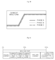
- a voltage of an output stage capacitor 80 may be measured and transmitted to each current controller 35, 45 and 55 by a voltage controller 60, and the current controllers 35, 45, and 55 for respective phases generate duty ratios to adjust respective phases and transmit the duty ratios to the interleaved converter 20 to adjust a current output from the converter 20. Therefore, equipping the current controllers 35, 45 and 55 in charge of respective phases may achieve a balance of currents output from respective phases as illustrated in FIG. 1B , however, the load on the MCU increases as illustrated in FIG. 1C .
- FIGS. 2A through FIG. 2C are exemplary diagrams for existing methods having one current controller 35 for the interleaved converter 20.
- the interleaved converter 20 in FIG. 2A may be configured to transmit an output from the input voltage source 10 using the three-phase interleaved converter 20, and operate the converters 30, 40 and 50 in charge of respective phases using one current controller 35.
- An output signal from the current controller 35 may be phase-shifted to operate an interleaved converter for another phase.
- the converters 40 and 50 in charge of phase B and phase C may phase-shift by about 120 degrees an output signal from the current controller 35 in charge of phase A using phase-shifters 90 and 95 to adjust phase B and phase C.
- one current controller may be used to generate a signal with a duty ratio for adjusting a current of the converter 30 that corresponds to the one current controller, and the converters 40 and 50 for other phases may be operated by phase-shifting a signal with the same duty ratio by about 120 degrees.
- This method has an advantage of reducing the load on the MCU, but also has a problem in that it does not instantly reflect precise current changes in other phases and therefore may cause a current imbalance.
- FIG. 3A through FIG. 3C are exemplary diagrams for a method and an apparatus for controlling a current of a multi-phase interleaved converter according to an exemplary embodiment of the present invention.
- FIG. 4 is an exemplary graph illustrating operation cycles of the current controller and the balancing controller depicted in FIG. 3 .
- a current control device 100 of the multi-phase interleaved converter may include an input voltage source 10, a multi-phase interleaved converter 20, a filter 300 and an interleave controller 70.
- the input voltage source 10 is a power input into the multi-phase interleaved converter 20, and the multi-phase interleaved converter 20 may be configured to convert an input voltage (Vin) into an output voltage (Vo).
- the multi-phase interleaved converter 20 may be, for example, a parallel connection of converters for phase A, phase B and phase C. An output stage of each converter may be connected with an output stage capacitor 80.
- the filter 300 may be configured to filter current inputs from the multi-phase interleaved converter 20 having multiple phases into the converters 30, 40 and 50 for respective phases. More specifically, the filter 300 may be configured to smooth all received currents that correspond to respective phases into direct current values to convert the direct current values into DC elements.
- the filter 300 may be, for example, a low pass filter, and a greater time constant of a low pass filter may lead to improved smoothing of a received current. In other words, the smaller the band width of the low pass filter 300 , the more precisely the current received by the filter 300 may be smoothed into a DC current value. Meanwhile, the filter 300 may be either hardware-based or software-based.
- the time constant of the filter 300 may be greater than a predetermined reference value, which is used to determine when the value of a current output from the filter 300 is a DC value.
- the filter 300 may be configured to eliminate AC elements as ripple elements and filter DC elements as offset elements. In other words, a current with ripple elements eliminated above a certain reference level may be considered a DC value.
- the interleave controller 70 may include a current controller 35 configured to sense a current (IA) flowing into any one of multiple phases to generate a duty ratio (DA) for a phase (phase A) that corresponds to the current and a balancing controller 310 configured to receive values of currents (IA_filter, IB_filter and IC_filter) for respective phases filtered by the filter 300 and the duty ratio (DA) generated in the current controller 35 to adjust duty ratios (DB and DC) for phases (phase B and phase C) other than the phase (phase A) based on the received current values (IA_filter, IB_filter and IC_filter) for respective phases.
- a current controller 35 configured to sense a current (IA) flowing into any one of multiple phases to generate a duty ratio (DA) for a phase (phase A) that corresponds to the current
- a balancing controller 310 configured to receive values of currents (IA_filter, IB_filter and IC_filter) for respective phases filtered by the filter 300 and the duty
- the interleave controller 70 may further contain phase-shifters 90 and 95 configured to apply a phase difference between respective phases (e.g., about 120 degrees for three phases) to the duty ratios (DB and DC) adjusted in the balancing controller 310 and transmit the duty ratios (DB and DC) with the phase difference applied to the converters 40 and 50 for phase B and phase C.
- phase shifters 90 and 95 when the phase shifters 90 and 95 are disposed within the balancing controller 310, extra phase shifters 90 and 95 may be omitted, and when extra phase shifters 90 and 95 are installed, the phase shifters 90 and 95 in the balancing controller 310 may be omitted.
- the current controller 35 may be configured to generate a duty ratio (DA) for any one phase (phase A) during a first cycle (T1).
- the balancing controller 310 may be configured to adjust duty ratios (DB and DC) for phases (phase B and phase C) other than the phase (phase A) during a second cycle (T2).
- DB and DC duty ratios
- the adjusting time of the balancing controller 310 may decrease and subsequently the balancing controlling time may also decrease as illustrated in FIG. 3c , thereby significantly reducing the load rate of the interleave controller (MCU) 70.
- the balancing controller 310 may be configured to compare the received current values (IA_filter, IB_filter and IC_filter) for respective phases and adjust the duty ratios to cause decreased current values to decrease duty ratios. In other words, as the current values of respective phases increase, the duty ratios for respective phases may be adjusted to be decreased, and as the current values of respective phases are decreased, the duty ratios for respective phases may be adjusted to increase.
- Current waveforms for respective phases may be obtained as illustrated in FIG. 3b after a phase-shift by the phase-shifters 90 and 95 and a balancing of current values for respective phases by the balancing controller 310.
- the current control device 100 of the multi-phase interleaved converter 20 may be configured to convert currents flowing into respective phases of the interleaved converter 20 into DC values using the filter 300, operate the balancing controller 310 to compare the current values converted into DC values and adjust the duty ratios that correspond to each current, and phase-shift the duty ratios adjusted by the phase-shifter 90 and 95, thereby operating ON/OFF of switches installed in the converters 30, 40 and 50 that correspond to respective phases.
- the method and apparatus for controlling a current of a multi-phase interleaved converter may apply a current controller configured to generate duty ratios for respective phases to one phase, to reduce the load on the MCU controlling such current controllers and decreasing cost.
- the method and apparatus may reduce or substantially eliminate current imbalances for respective phases possibly resulting from some factors such as tolerance of an inductor and resistance.
Landscapes
- Engineering & Computer Science (AREA)
- Power Engineering (AREA)
- Dc-Dc Converters (AREA)
Applications Claiming Priority (1)
| Application Number | Priority Date | Filing Date | Title |
|---|---|---|---|
| KR1020140095952A KR101592744B1 (ko) | 2014-07-28 | 2014-07-28 | 다상 인터리브 컨버터의 전류 제어 방법 및 장치 |
Publications (2)
| Publication Number | Publication Date |
|---|---|
| EP2980974A1 true EP2980974A1 (de) | 2016-02-03 |
| EP2980974B1 EP2980974B1 (de) | 2021-10-06 |
Family
ID=52006888
Family Applications (1)
| Application Number | Title | Priority Date | Filing Date |
|---|---|---|---|
| EP14196269.6A Active EP2980974B1 (de) | 2014-07-28 | 2014-12-04 | Verfahren und Vorrichtung zur Stromregelung eines mehrphasigen verschachtelten Wandlers |
Country Status (4)
| Country | Link |
|---|---|
| US (1) | US9553518B2 (de) |
| EP (1) | EP2980974B1 (de) |
| KR (1) | KR101592744B1 (de) |
| CN (1) | CN105322782B (de) |
Cited By (2)
| Publication number | Priority date | Publication date | Assignee | Title |
|---|---|---|---|---|
| WO2018069076A1 (de) * | 2016-10-11 | 2018-04-19 | Robert Bosch Gmbh | Regelvorrichtung für einen gleichspannungskonverter, gleichspannungskonverter und verfahren zur regelung eines gleichspannungskonverters |
| WO2022139091A1 (ko) * | 2020-12-24 | 2022-06-30 | (주)실리콘인사이드 | 전류 발란싱 회로의 오프셋 상쇠 회로 |
Families Citing this family (4)
| Publication number | Priority date | Publication date | Assignee | Title |
|---|---|---|---|---|
| JP6998252B2 (ja) * | 2018-03-28 | 2022-01-18 | 株式会社Gsユアサ インフラシステムズ | スイッチング電源装置 |
| WO2021095216A1 (ja) * | 2019-11-14 | 2021-05-20 | 三菱電機株式会社 | 電力変換装置、モータ駆動装置、送風機、圧縮機及び空気調和機 |
| CN114629350B (zh) * | 2022-01-25 | 2025-06-13 | 西安理工大学 | 四相交错并联高增益Boost变换器的均流方法 |
| GB202307717D0 (en) * | 2023-05-23 | 2023-07-05 | Tdk Lambda Uk Ltd | Controller for a multi-phase power converter, multi-phase power converter, multi-phase power converter and method |
Citations (3)
| Publication number | Priority date | Publication date | Assignee | Title |
|---|---|---|---|---|
| US20130114306A1 (en) * | 2011-11-08 | 2013-05-09 | Lincoln Global, Inc. | Dynamic power factor correction and dynamic control for converter in power supply |
| US20130320951A1 (en) * | 2012-05-30 | 2013-12-05 | Linear Technology Corporation | Expanding dc/dc converter into multiphase dc/dc converter |
| US20140167711A1 (en) * | 2012-12-19 | 2014-06-19 | Fenardi Thenus | Method and apparatus of current balancing for multiple phase power converter |
Family Cites Families (13)
| Publication number | Priority date | Publication date | Assignee | Title |
|---|---|---|---|---|
| US6628106B1 (en) * | 2001-07-30 | 2003-09-30 | University Of Central Florida | Control method and circuit to provide voltage and current regulation for multiphase DC/DC converters |
| US7466116B2 (en) | 2004-04-12 | 2008-12-16 | Renesas Technology America, Inc. | Current sensing circuit for a multi-phase DC-DC converter |
| US7342386B2 (en) | 2006-05-10 | 2008-03-11 | Astec International Limited | Multiphase power converter having balanced currents |
| JP2009081930A (ja) | 2007-09-26 | 2009-04-16 | Jtekt Corp | モータ制御装置および電動パワーステアリング装置 |
| US7710082B2 (en) | 2007-10-18 | 2010-05-04 | Instituto Potosino De Investigacion Cientifica Y Technologica (Ipicyt) | Controller for the three-phase cascade multilevel converter used as shunt active filter in unbalanced operation with guaranteed capacitors voltages balance |
| CN101594049B (zh) * | 2008-05-30 | 2012-06-06 | 艾默生网络能源有限公司 | 交错并联pfc控制电路及控制方法 |
| JP2010041867A (ja) | 2008-08-07 | 2010-02-18 | Denso Corp | 多相回転機の制御装置 |
| US8089256B2 (en) | 2008-10-10 | 2012-01-03 | Powervation Ltd. | Multiphase switching converter |
| US9998008B2 (en) * | 2013-01-09 | 2018-06-12 | Infineon Technologies Austria Ag | Active transient response for DC-DC converters |
| CN103248231B (zh) * | 2013-04-02 | 2015-12-23 | 浙江大学 | 多相均流控制的并联调整电路控制方法 |
| TWI506909B (zh) * | 2013-11-22 | 2015-11-01 | Accton Technology Corp | 電源共享裝置及方法 |
| KR101500206B1 (ko) | 2013-11-26 | 2015-03-06 | 현대자동차주식회사 | 2상 인터리브 컨버터 및 이의 제어 방법 |
| US9748839B2 (en) * | 2014-03-31 | 2017-08-29 | Infineon Technologies Austria Ag | Digital voltage regulator controller with multiple configurations |
-
2014
- 2014-07-28 KR KR1020140095952A patent/KR101592744B1/ko active Active
- 2014-12-03 US US14/559,663 patent/US9553518B2/en active Active
- 2014-12-04 EP EP14196269.6A patent/EP2980974B1/de active Active
- 2014-12-08 CN CN201410745774.7A patent/CN105322782B/zh active Active
Patent Citations (3)
| Publication number | Priority date | Publication date | Assignee | Title |
|---|---|---|---|---|
| US20130114306A1 (en) * | 2011-11-08 | 2013-05-09 | Lincoln Global, Inc. | Dynamic power factor correction and dynamic control for converter in power supply |
| US20130320951A1 (en) * | 2012-05-30 | 2013-12-05 | Linear Technology Corporation | Expanding dc/dc converter into multiphase dc/dc converter |
| US20140167711A1 (en) * | 2012-12-19 | 2014-06-19 | Fenardi Thenus | Method and apparatus of current balancing for multiple phase power converter |
Cited By (3)
| Publication number | Priority date | Publication date | Assignee | Title |
|---|---|---|---|---|
| WO2018069076A1 (de) * | 2016-10-11 | 2018-04-19 | Robert Bosch Gmbh | Regelvorrichtung für einen gleichspannungskonverter, gleichspannungskonverter und verfahren zur regelung eines gleichspannungskonverters |
| US10707748B2 (en) | 2016-10-11 | 2020-07-07 | Robert Bosch Gmbh | Control device for DC converter, DC converter, and method for controlling a DC converter |
| WO2022139091A1 (ko) * | 2020-12-24 | 2022-06-30 | (주)실리콘인사이드 | 전류 발란싱 회로의 오프셋 상쇠 회로 |
Also Published As
| Publication number | Publication date |
|---|---|
| EP2980974B1 (de) | 2021-10-06 |
| CN105322782A (zh) | 2016-02-10 |
| KR101592744B1 (ko) | 2016-02-15 |
| CN105322782B (zh) | 2019-05-10 |
| US9553518B2 (en) | 2017-01-24 |
| KR20160014198A (ko) | 2016-02-11 |
| US20160028312A1 (en) | 2016-01-28 |
Similar Documents
| Publication | Publication Date | Title |
|---|---|---|
| US9553518B2 (en) | Method and apparatus for controlling current of multi-phase interleaved converter | |
| CN101540583B (zh) | 马达控制器 | |
| US11264821B2 (en) | Bidirectional on-board charger and method of controlling the same | |
| CN105099152B (zh) | 多相交织转换器及其控制方法 | |
| US11296536B2 (en) | Charging power supplying system using motor driving system | |
| US20120235607A1 (en) | Dc bus boost method and system for regenerative brake | |
| Chen et al. | Modified interleaved current sensorless control for three-level boost PFC converter with considering voltage imbalance and zero-crossing current distortion | |
| EP3267556B1 (de) | Verfahren und system zum steuern des ladens von elektrofahrzeugen | |
| EP3238334B1 (de) | Dreiphasiges ladegerät mit breitem eingangsspannungsbereich mit flexiblen einphasigen eingangsoptionen | |
| EP2768108A1 (de) | Montiertes ladesystem | |
| US20160137080A1 (en) | Apparatus and method for charging battery for vehicle | |
| EP2552005A1 (de) | Stromwandler | |
| Gulbudak et al. | Model predictive control of dual-output nine-switch inverter with output filter | |
| JP6798286B2 (ja) | 電動車両の充電システム及び車載充電ユニット | |
| EP2728723A1 (de) | Betrieb von mehrkanaligem Aktivgleichrichter | |
| EP3442112A1 (de) | Elektromotorvorrichtung | |
| WO2019182161A1 (ja) | 電力変換システム、電力変換装置、電力変換方法、発電システム、有効電力授受システム、電力系統、電力授受システム、負荷システム及び送配電システム | |
| CN106685036B (zh) | 充电机及其充电方法和装置及电动汽车 | |
| KR20140100339A (ko) | 충전 장치, 및 이를 구비하는 전기 차량 | |
| CA3178118A1 (en) | Drivetrain integrated traction-to-auxiliary converter for inverter base d electric vehicles | |
| EP2871764B1 (de) | Stromwandler | |
| JP2013172466A (ja) | 電力変換装置及びこれを用いた系統連系システム | |
| Chen et al. | A control strategy enabling compatible 1-ph/3-ph V2L operations for EV chargers with improved leg utilizations | |
| CN113541510A (zh) | 一种交流-直流电能变换系统及方法 | |
| EP4683197A1 (de) | Wechselstrom-gleichstrom-wandler, verfahren zur steuerung eines wechselstrom-gleichstrom-wandlers und computerprogrammprodukt |
Legal Events
| Date | Code | Title | Description |
|---|---|---|---|
| PUAI | Public reference made under article 153(3) epc to a published international application that has entered the european phase |
Free format text: ORIGINAL CODE: 0009012 |
|
| AK | Designated contracting states |
Kind code of ref document: A1 Designated state(s): AL AT BE BG CH CY CZ DE DK EE ES FI FR GB GR HR HU IE IS IT LI LT LU LV MC MK MT NL NO PL PT RO RS SE SI SK SM TR |
|
| AX | Request for extension of the european patent |
Extension state: BA ME |
|
| 17P | Request for examination filed |
Effective date: 20160802 |
|
| RBV | Designated contracting states (corrected) |
Designated state(s): AL AT BE BG CH CY CZ DE DK EE ES FI FR GB GR HR HU IE IS IT LI LT LU LV MC MK MT NL NO PL PT RO RS SE SI SK SM TR |
|
| STAA | Information on the status of an ep patent application or granted ep patent |
Free format text: STATUS: EXAMINATION IS IN PROGRESS |
|
| 17Q | First examination report despatched |
Effective date: 20200805 |
|
| GRAP | Despatch of communication of intention to grant a patent |
Free format text: ORIGINAL CODE: EPIDOSNIGR1 |
|
| STAA | Information on the status of an ep patent application or granted ep patent |
Free format text: STATUS: GRANT OF PATENT IS INTENDED |
|
| INTG | Intention to grant announced |
Effective date: 20210504 |
|
| GRAS | Grant fee paid |
Free format text: ORIGINAL CODE: EPIDOSNIGR3 |
|
| GRAA | (expected) grant |
Free format text: ORIGINAL CODE: 0009210 |
|
| STAA | Information on the status of an ep patent application or granted ep patent |
Free format text: STATUS: THE PATENT HAS BEEN GRANTED |
|
| AK | Designated contracting states |
Kind code of ref document: B1 Designated state(s): AL AT BE BG CH CY CZ DE DK EE ES FI FR GB GR HR HU IE IS IT LI LT LU LV MC MK MT NL NO PL PT RO RS SE SI SK SM TR |
|
| REG | Reference to a national code |
Ref country code: GB Ref legal event code: FG4D |
|
| REG | Reference to a national code |
Ref country code: CH Ref legal event code: EP Ref country code: AT Ref legal event code: REF Ref document number: 1437051 Country of ref document: AT Kind code of ref document: T Effective date: 20211015 |
|
| REG | Reference to a national code |
Ref country code: IE Ref legal event code: FG4D |
|
| REG | Reference to a national code |
Ref country code: DE Ref legal event code: R096 Ref document number: 602014080484 Country of ref document: DE |
|
| REG | Reference to a national code |
Ref country code: LT Ref legal event code: MG9D |
|
| REG | Reference to a national code |
Ref country code: NL Ref legal event code: MP Effective date: 20211006 |
|
| REG | Reference to a national code |
Ref country code: AT Ref legal event code: MK05 Ref document number: 1437051 Country of ref document: AT Kind code of ref document: T Effective date: 20211006 |
|
| PG25 | Lapsed in a contracting state [announced via postgrant information from national office to epo] |
Ref country code: RS Free format text: LAPSE BECAUSE OF FAILURE TO SUBMIT A TRANSLATION OF THE DESCRIPTION OR TO PAY THE FEE WITHIN THE PRESCRIBED TIME-LIMIT Effective date: 20211006 Ref country code: LT Free format text: LAPSE BECAUSE OF FAILURE TO SUBMIT A TRANSLATION OF THE DESCRIPTION OR TO PAY THE FEE WITHIN THE PRESCRIBED TIME-LIMIT Effective date: 20211006 Ref country code: FI Free format text: LAPSE BECAUSE OF FAILURE TO SUBMIT A TRANSLATION OF THE DESCRIPTION OR TO PAY THE FEE WITHIN THE PRESCRIBED TIME-LIMIT Effective date: 20211006 Ref country code: BG Free format text: LAPSE BECAUSE OF FAILURE TO SUBMIT A TRANSLATION OF THE DESCRIPTION OR TO PAY THE FEE WITHIN THE PRESCRIBED TIME-LIMIT Effective date: 20220106 Ref country code: AT Free format text: LAPSE BECAUSE OF FAILURE TO SUBMIT A TRANSLATION OF THE DESCRIPTION OR TO PAY THE FEE WITHIN THE PRESCRIBED TIME-LIMIT Effective date: 20211006 |
|
| PG25 | Lapsed in a contracting state [announced via postgrant information from national office to epo] |
Ref country code: IS Free format text: LAPSE BECAUSE OF FAILURE TO SUBMIT A TRANSLATION OF THE DESCRIPTION OR TO PAY THE FEE WITHIN THE PRESCRIBED TIME-LIMIT Effective date: 20220206 Ref country code: SE Free format text: LAPSE BECAUSE OF FAILURE TO SUBMIT A TRANSLATION OF THE DESCRIPTION OR TO PAY THE FEE WITHIN THE PRESCRIBED TIME-LIMIT Effective date: 20211006 Ref country code: PT Free format text: LAPSE BECAUSE OF FAILURE TO SUBMIT A TRANSLATION OF THE DESCRIPTION OR TO PAY THE FEE WITHIN THE PRESCRIBED TIME-LIMIT Effective date: 20220207 Ref country code: PL Free format text: LAPSE BECAUSE OF FAILURE TO SUBMIT A TRANSLATION OF THE DESCRIPTION OR TO PAY THE FEE WITHIN THE PRESCRIBED TIME-LIMIT Effective date: 20211006 Ref country code: NO Free format text: LAPSE BECAUSE OF FAILURE TO SUBMIT A TRANSLATION OF THE DESCRIPTION OR TO PAY THE FEE WITHIN THE PRESCRIBED TIME-LIMIT Effective date: 20220106 Ref country code: NL Free format text: LAPSE BECAUSE OF FAILURE TO SUBMIT A TRANSLATION OF THE DESCRIPTION OR TO PAY THE FEE WITHIN THE PRESCRIBED TIME-LIMIT Effective date: 20211006 Ref country code: LV Free format text: LAPSE BECAUSE OF FAILURE TO SUBMIT A TRANSLATION OF THE DESCRIPTION OR TO PAY THE FEE WITHIN THE PRESCRIBED TIME-LIMIT Effective date: 20211006 Ref country code: HR Free format text: LAPSE BECAUSE OF FAILURE TO SUBMIT A TRANSLATION OF THE DESCRIPTION OR TO PAY THE FEE WITHIN THE PRESCRIBED TIME-LIMIT Effective date: 20211006 Ref country code: GR Free format text: LAPSE BECAUSE OF FAILURE TO SUBMIT A TRANSLATION OF THE DESCRIPTION OR TO PAY THE FEE WITHIN THE PRESCRIBED TIME-LIMIT Effective date: 20220107 Ref country code: ES Free format text: LAPSE BECAUSE OF FAILURE TO SUBMIT A TRANSLATION OF THE DESCRIPTION OR TO PAY THE FEE WITHIN THE PRESCRIBED TIME-LIMIT Effective date: 20211006 |
|
| REG | Reference to a national code |
Ref country code: DE Ref legal event code: R097 Ref document number: 602014080484 Country of ref document: DE |
|
| PG25 | Lapsed in a contracting state [announced via postgrant information from national office to epo] |
Ref country code: SM Free format text: LAPSE BECAUSE OF FAILURE TO SUBMIT A TRANSLATION OF THE DESCRIPTION OR TO PAY THE FEE WITHIN THE PRESCRIBED TIME-LIMIT Effective date: 20211006 Ref country code: SK Free format text: LAPSE BECAUSE OF FAILURE TO SUBMIT A TRANSLATION OF THE DESCRIPTION OR TO PAY THE FEE WITHIN THE PRESCRIBED TIME-LIMIT Effective date: 20211006 Ref country code: RO Free format text: LAPSE BECAUSE OF FAILURE TO SUBMIT A TRANSLATION OF THE DESCRIPTION OR TO PAY THE FEE WITHIN THE PRESCRIBED TIME-LIMIT Effective date: 20211006 Ref country code: MC Free format text: LAPSE BECAUSE OF FAILURE TO SUBMIT A TRANSLATION OF THE DESCRIPTION OR TO PAY THE FEE WITHIN THE PRESCRIBED TIME-LIMIT Effective date: 20211006 Ref country code: EE Free format text: LAPSE BECAUSE OF FAILURE TO SUBMIT A TRANSLATION OF THE DESCRIPTION OR TO PAY THE FEE WITHIN THE PRESCRIBED TIME-LIMIT Effective date: 20211006 Ref country code: DK Free format text: LAPSE BECAUSE OF FAILURE TO SUBMIT A TRANSLATION OF THE DESCRIPTION OR TO PAY THE FEE WITHIN THE PRESCRIBED TIME-LIMIT Effective date: 20211006 Ref country code: CZ Free format text: LAPSE BECAUSE OF FAILURE TO SUBMIT A TRANSLATION OF THE DESCRIPTION OR TO PAY THE FEE WITHIN THE PRESCRIBED TIME-LIMIT Effective date: 20211006 |
|
| REG | Reference to a national code |
Ref country code: CH Ref legal event code: PL |
|
| PLBE | No opposition filed within time limit |
Free format text: ORIGINAL CODE: 0009261 |
|
| STAA | Information on the status of an ep patent application or granted ep patent |
Free format text: STATUS: NO OPPOSITION FILED WITHIN TIME LIMIT |
|
| 26N | No opposition filed |
Effective date: 20220707 |
|
| REG | Reference to a national code |
Ref country code: BE Ref legal event code: MM Effective date: 20211231 |
|
| PG25 | Lapsed in a contracting state [announced via postgrant information from national office to epo] |
Ref country code: LU Free format text: LAPSE BECAUSE OF NON-PAYMENT OF DUE FEES Effective date: 20211204 Ref country code: IE Free format text: LAPSE BECAUSE OF NON-PAYMENT OF DUE FEES Effective date: 20211204 Ref country code: AL Free format text: LAPSE BECAUSE OF FAILURE TO SUBMIT A TRANSLATION OF THE DESCRIPTION OR TO PAY THE FEE WITHIN THE PRESCRIBED TIME-LIMIT Effective date: 20211006 |
|
| PG25 | Lapsed in a contracting state [announced via postgrant information from national office to epo] |
Ref country code: SI Free format text: LAPSE BECAUSE OF FAILURE TO SUBMIT A TRANSLATION OF THE DESCRIPTION OR TO PAY THE FEE WITHIN THE PRESCRIBED TIME-LIMIT Effective date: 20211006 Ref country code: BE Free format text: LAPSE BECAUSE OF NON-PAYMENT OF DUE FEES Effective date: 20211231 |
|
| PG25 | Lapsed in a contracting state [announced via postgrant information from national office to epo] |
Ref country code: LI Free format text: LAPSE BECAUSE OF NON-PAYMENT OF DUE FEES Effective date: 20211231 Ref country code: CH Free format text: LAPSE BECAUSE OF NON-PAYMENT OF DUE FEES Effective date: 20211231 |
|
| PG25 | Lapsed in a contracting state [announced via postgrant information from national office to epo] |
Ref country code: IT Free format text: LAPSE BECAUSE OF FAILURE TO SUBMIT A TRANSLATION OF THE DESCRIPTION OR TO PAY THE FEE WITHIN THE PRESCRIBED TIME-LIMIT Effective date: 20211006 Ref country code: HU Free format text: LAPSE BECAUSE OF FAILURE TO SUBMIT A TRANSLATION OF THE DESCRIPTION OR TO PAY THE FEE WITHIN THE PRESCRIBED TIME-LIMIT; INVALID AB INITIO Effective date: 20141204 |
|
| P01 | Opt-out of the competence of the unified patent court (upc) registered |
Effective date: 20230511 |
|
| PG25 | Lapsed in a contracting state [announced via postgrant information from national office to epo] |
Ref country code: CY Free format text: LAPSE BECAUSE OF FAILURE TO SUBMIT A TRANSLATION OF THE DESCRIPTION OR TO PAY THE FEE WITHIN THE PRESCRIBED TIME-LIMIT Effective date: 20211006 |
|
| PG25 | Lapsed in a contracting state [announced via postgrant information from national office to epo] |
Ref country code: MK Free format text: LAPSE BECAUSE OF FAILURE TO SUBMIT A TRANSLATION OF THE DESCRIPTION OR TO PAY THE FEE WITHIN THE PRESCRIBED TIME-LIMIT Effective date: 20211006 |
|
| PG25 | Lapsed in a contracting state [announced via postgrant information from national office to epo] |
Ref country code: TR Free format text: LAPSE BECAUSE OF FAILURE TO SUBMIT A TRANSLATION OF THE DESCRIPTION OR TO PAY THE FEE WITHIN THE PRESCRIBED TIME-LIMIT Effective date: 20211006 |
|
| PG25 | Lapsed in a contracting state [announced via postgrant information from national office to epo] |
Ref country code: MT Free format text: LAPSE BECAUSE OF FAILURE TO SUBMIT A TRANSLATION OF THE DESCRIPTION OR TO PAY THE FEE WITHIN THE PRESCRIBED TIME-LIMIT Effective date: 20211006 |
|
| PGFP | Annual fee paid to national office [announced via postgrant information from national office to epo] |
Ref country code: GB Payment date: 20241121 Year of fee payment: 11 |
|
| PGFP | Annual fee paid to national office [announced via postgrant information from national office to epo] |
Ref country code: FR Payment date: 20241121 Year of fee payment: 11 |
|
| PGFP | Annual fee paid to national office [announced via postgrant information from national office to epo] |
Ref country code: DE Payment date: 20251120 Year of fee payment: 12 |