EP2980947B1 - Power management system and refrigerator - Google Patents
Power management system and refrigerator Download PDFInfo
- Publication number
- EP2980947B1 EP2980947B1 EP14776348.6A EP14776348A EP2980947B1 EP 2980947 B1 EP2980947 B1 EP 2980947B1 EP 14776348 A EP14776348 A EP 14776348A EP 2980947 B1 EP2980947 B1 EP 2980947B1
- Authority
- EP
- European Patent Office
- Prior art keywords
- power
- power supply
- difficulty
- refrigerator
- reduction
- Prior art date
- Legal status (The legal status is an assumption and is not a legal conclusion. Google has not performed a legal analysis and makes no representation as to the accuracy of the status listed.)
- Not-in-force
Links
Images


Classifications
-
- G—PHYSICS
- G05—CONTROLLING; REGULATING
- G05F—SYSTEMS FOR REGULATING ELECTRIC OR MAGNETIC VARIABLES
- G05F1/00—Automatic systems in which deviations of an electric quantity from one or more predetermined values are detected at the output of the system and fed back to a device within the system to restore the detected quantity to its predetermined value or values, i.e. retroactive systems
- G05F1/66—Regulating electric power
-
- F—MECHANICAL ENGINEERING; LIGHTING; HEATING; WEAPONS; BLASTING
- F25—REFRIGERATION OR COOLING; COMBINED HEATING AND REFRIGERATION SYSTEMS; HEAT PUMP SYSTEMS; MANUFACTURE OR STORAGE OF ICE; LIQUEFACTION SOLIDIFICATION OF GASES
- F25D—REFRIGERATORS; COLD ROOMS; ICE-BOXES; COOLING OR FREEZING APPARATUS NOT OTHERWISE PROVIDED FOR
- F25D29/00—Arrangement or mounting of control or safety devices
-
- G—PHYSICS
- G05—CONTROLLING; REGULATING
- G05B—CONTROL OR REGULATING SYSTEMS IN GENERAL; FUNCTIONAL ELEMENTS OF SUCH SYSTEMS; MONITORING OR TESTING ARRANGEMENTS FOR SUCH SYSTEMS OR ELEMENTS
- G05B15/00—Systems controlled by a computer
- G05B15/02—Systems controlled by a computer electric
-
- H—ELECTRICITY
- H02—GENERATION; CONVERSION OR DISTRIBUTION OF ELECTRIC POWER
- H02J—CIRCUIT ARRANGEMENTS OR SYSTEMS FOR SUPPLYING OR DISTRIBUTING ELECTRIC POWER; SYSTEMS FOR STORING ELECTRIC ENERGY
- H02J13/00—Circuit arrangements for providing remote indication of network conditions, e.g. an instantaneous record of the open or closed condition of each circuitbreaker in the network; Circuit arrangements for providing remote control of switching means in a power distribution network, e.g. switching in and out of current consumers by using a pulse code signal carried by the network
- H02J13/00004—Circuit arrangements for providing remote indication of network conditions, e.g. an instantaneous record of the open or closed condition of each circuitbreaker in the network; Circuit arrangements for providing remote control of switching means in a power distribution network, e.g. switching in and out of current consumers by using a pulse code signal carried by the network characterised by the power network being locally controlled
-
- H—ELECTRICITY
- H02—GENERATION; CONVERSION OR DISTRIBUTION OF ELECTRIC POWER
- H02J—CIRCUIT ARRANGEMENTS OR SYSTEMS FOR SUPPLYING OR DISTRIBUTING ELECTRIC POWER; SYSTEMS FOR STORING ELECTRIC ENERGY
- H02J3/00—Circuit arrangements for ac mains or ac distribution networks
- H02J3/12—Circuit arrangements for ac mains or ac distribution networks for adjusting voltage in ac networks by changing a characteristic of the network load
- H02J3/14—Circuit arrangements for ac mains or ac distribution networks for adjusting voltage in ac networks by changing a characteristic of the network load by switching loads on to, or off from, network, e.g. progressively balanced loading
-
- H—ELECTRICITY
- H02—GENERATION; CONVERSION OR DISTRIBUTION OF ELECTRIC POWER
- H02J—CIRCUIT ARRANGEMENTS OR SYSTEMS FOR SUPPLYING OR DISTRIBUTING ELECTRIC POWER; SYSTEMS FOR STORING ELECTRIC ENERGY
- H02J13/00—Circuit arrangements for providing remote indication of network conditions, e.g. an instantaneous record of the open or closed condition of each circuitbreaker in the network; Circuit arrangements for providing remote control of switching means in a power distribution network, e.g. switching in and out of current consumers by using a pulse code signal carried by the network
- H02J13/00002—Circuit arrangements for providing remote indication of network conditions, e.g. an instantaneous record of the open or closed condition of each circuitbreaker in the network; Circuit arrangements for providing remote control of switching means in a power distribution network, e.g. switching in and out of current consumers by using a pulse code signal carried by the network characterised by monitoring
-
- H—ELECTRICITY
- H02—GENERATION; CONVERSION OR DISTRIBUTION OF ELECTRIC POWER
- H02J—CIRCUIT ARRANGEMENTS OR SYSTEMS FOR SUPPLYING OR DISTRIBUTING ELECTRIC POWER; SYSTEMS FOR STORING ELECTRIC ENERGY
- H02J2310/00—The network for supplying or distributing electric power characterised by its spatial reach or by the load
- H02J2310/10—The network having a local or delimited stationary reach
- H02J2310/12—The local stationary network supplying a household or a building
- H02J2310/14—The load or loads being home appliances
-
- Y—GENERAL TAGGING OF NEW TECHNOLOGICAL DEVELOPMENTS; GENERAL TAGGING OF CROSS-SECTIONAL TECHNOLOGIES SPANNING OVER SEVERAL SECTIONS OF THE IPC; TECHNICAL SUBJECTS COVERED BY FORMER USPC CROSS-REFERENCE ART COLLECTIONS [XRACs] AND DIGESTS
- Y02—TECHNOLOGIES OR APPLICATIONS FOR MITIGATION OR ADAPTATION AGAINST CLIMATE CHANGE
- Y02B—CLIMATE CHANGE MITIGATION TECHNOLOGIES RELATED TO BUILDINGS, e.g. HOUSING, HOUSE APPLIANCES OR RELATED END-USER APPLICATIONS
- Y02B70/00—Technologies for an efficient end-user side electric power management and consumption
- Y02B70/30—Systems integrating technologies related to power network operation and communication or information technologies for improving the carbon footprint of the management of residential or tertiary loads, i.e. smart grids as climate change mitigation technology in the buildings sector, including also the last stages of power distribution and the control, monitoring or operating management systems at local level
- Y02B70/3225—Demand response systems, e.g. load shedding, peak shaving
-
- Y—GENERAL TAGGING OF NEW TECHNOLOGICAL DEVELOPMENTS; GENERAL TAGGING OF CROSS-SECTIONAL TECHNOLOGIES SPANNING OVER SEVERAL SECTIONS OF THE IPC; TECHNICAL SUBJECTS COVERED BY FORMER USPC CROSS-REFERENCE ART COLLECTIONS [XRACs] AND DIGESTS
- Y02—TECHNOLOGIES OR APPLICATIONS FOR MITIGATION OR ADAPTATION AGAINST CLIMATE CHANGE
- Y02E—REDUCTION OF GREENHOUSE GAS [GHG] EMISSIONS, RELATED TO ENERGY GENERATION, TRANSMISSION OR DISTRIBUTION
- Y02E60/00—Enabling technologies; Technologies with a potential or indirect contribution to GHG emissions mitigation
-
- Y—GENERAL TAGGING OF NEW TECHNOLOGICAL DEVELOPMENTS; GENERAL TAGGING OF CROSS-SECTIONAL TECHNOLOGIES SPANNING OVER SEVERAL SECTIONS OF THE IPC; TECHNICAL SUBJECTS COVERED BY FORMER USPC CROSS-REFERENCE ART COLLECTIONS [XRACs] AND DIGESTS
- Y04—INFORMATION OR COMMUNICATION TECHNOLOGIES HAVING AN IMPACT ON OTHER TECHNOLOGY AREAS
- Y04S—SYSTEMS INTEGRATING TECHNOLOGIES RELATED TO POWER NETWORK OPERATION, COMMUNICATION OR INFORMATION TECHNOLOGIES FOR IMPROVING THE ELECTRICAL POWER GENERATION, TRANSMISSION, DISTRIBUTION, MANAGEMENT OR USAGE, i.e. SMART GRIDS
- Y04S10/00—Systems supporting electrical power generation, transmission or distribution
- Y04S10/30—State monitoring, e.g. fault, temperature monitoring, insulator monitoring, corona discharge
-
- Y—GENERAL TAGGING OF NEW TECHNOLOGICAL DEVELOPMENTS; GENERAL TAGGING OF CROSS-SECTIONAL TECHNOLOGIES SPANNING OVER SEVERAL SECTIONS OF THE IPC; TECHNICAL SUBJECTS COVERED BY FORMER USPC CROSS-REFERENCE ART COLLECTIONS [XRACs] AND DIGESTS
- Y04—INFORMATION OR COMMUNICATION TECHNOLOGIES HAVING AN IMPACT ON OTHER TECHNOLOGY AREAS
- Y04S—SYSTEMS INTEGRATING TECHNOLOGIES RELATED TO POWER NETWORK OPERATION, COMMUNICATION OR INFORMATION TECHNOLOGIES FOR IMPROVING THE ELECTRICAL POWER GENERATION, TRANSMISSION, DISTRIBUTION, MANAGEMENT OR USAGE, i.e. SMART GRIDS
- Y04S20/00—Management or operation of end-user stationary applications or the last stages of power distribution; Controlling, monitoring or operating thereof
- Y04S20/20—End-user application control systems
- Y04S20/222—Demand response systems, e.g. load shedding, peak shaving
-
- Y—GENERAL TAGGING OF NEW TECHNOLOGICAL DEVELOPMENTS; GENERAL TAGGING OF CROSS-SECTIONAL TECHNOLOGIES SPANNING OVER SEVERAL SECTIONS OF THE IPC; TECHNICAL SUBJECTS COVERED BY FORMER USPC CROSS-REFERENCE ART COLLECTIONS [XRACs] AND DIGESTS
- Y04—INFORMATION OR COMMUNICATION TECHNOLOGIES HAVING AN IMPACT ON OTHER TECHNOLOGY AREAS
- Y04S—SYSTEMS INTEGRATING TECHNOLOGIES RELATED TO POWER NETWORK OPERATION, COMMUNICATION OR INFORMATION TECHNOLOGIES FOR IMPROVING THE ELECTRICAL POWER GENERATION, TRANSMISSION, DISTRIBUTION, MANAGEMENT OR USAGE, i.e. SMART GRIDS
- Y04S20/00—Management or operation of end-user stationary applications or the last stages of power distribution; Controlling, monitoring or operating thereof
- Y04S20/20—End-user application control systems
- Y04S20/242—Home appliances
Definitions
- the present invention relates to a power management system that reduces power to be used by an electric device.
- Patent Literature 1 discloses that when a measured current value does not decrease to a predetermined current before elapse of a predetermined time after exceeding a preset warning reference quantity, power supply to predetermined load devices is individually cut, thereby preventing power supply to all the load devices from being cut simultaneously by a current limiter or a breaker due to overuse of electricity.
- a control method of a refrigerator connected to an electric power management network comprises steps of receiving power-rate information via the electric power management network; setting an over-cooling period and a power-saving period based on the received power-rate information; controlling at east one storage chamber to be over-cooled by over-cooling cold air during the over-cooling period; and controlling the other storage chamber to be over-cooled by the over-cooled cold air during the power-saving period.
- the functions of the refrigerator are provided with minimal use of electricity and/or with reduced electricity charges.
- Patent Literature 1 Japanese Unexamined Patent Application Publication No. 11-296771
- a refrigerator is an electric device, which is desired to continuously operate to cool and store food.
- power supply to a refrigerator is also cut similarly to the other electric devices as in Patent Literature 1, the disadvantage increases.
- the present invention has been made to solve the above-described problem, and an object of the present invention is to provide a power management system that reduces power consumption without stopping power supply to an electric device such as a refrigerator, which is desired to continuously operate.
- a power management system according to the present invention includes the features of independent claim 1.
- the power reduction control at the refrigerator is selected and executed in accordance with the power supply difficulty, thereby reducing power consumption without turning off the refrigerator.
- the power supply difficulty without impairing comfort for the user in a range where it is possible to supply power.
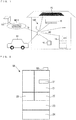
- Fig. 1 is a system configuration diagram showing Embodiment 1 of a power management system of the present invention, and a power management system 100 will be described with reference to Fig. 1 .
- the power management system 100 in Fig. 1 manages power, for example, of a plurality of electric devices 1A to 1C installed in a house (HEMS: HOME ENERGY MANAGEMENT SYSTEM).
- the plurality of electric devices 1A to 1C is connected to a centralized controller 2 via a wire or a wireless network NW.
- the centralized controller 2 is connected to an external network NW10, and is configured to be able to acquire power supply information ED indicating a power supply state, for example, from an electric power company 101.
- examples of the plurality of electric devices connected to the centralized controller 2 include a refrigerator 1A, an air-conditioning device 1B, and an installation-type or tablet-type information terminal device (interface device) 1C.
- the centralized controller 2 is also connected to the installation-type or tablet-type information terminal device 1C, and a user is allowed to confirm a power use state or operate each device by using the information terminal device 1C.
- the electric devices 1A to 1C connected to the centralized controller 2 are not limited to the above types, and devices such as a water heater, a lighting device, and a television may be connected thereto.
- the power management system 100 cooperates with an electric vehicle EV and a solar power generation panel PV, and power generated in the solar power generation panel PV is supplied to the plurality of electric devices 1A to 1C and is stored in a storage battery of the electric vehicle EV.
- the power stored in the storage battery of the electric vehicle EV is supplied to the plurality of electric devices 1A to 1C.
- the centralized controller 2 has a function of adjusting a power load in a household based on power generation/charge states of the solar power generation panel PV and the electric vehicle EV.
- Fig. 2 is a schematic front view showing Embodiment 1 of the refrigerator of the present invention
- Fig. 3 is a schematic cross-sectional view of Embodiment 1 of the refrigerator of the present invention
- the refrigerator 1A will be described with reference to Figs. 2 and 3 .
- the refrigerator 1A includes a refrigerating compartment 11 provided at the uppermost stage, and a plurality of storage compartments 12 to 14 provided below the refrigerating compartment 11.
- a door 21 is disposed at the front of the refrigerating compartment 11, and doors 22 to 25 are disposed at the front of the respective storage compartments 12 to 14.
- An operation panel 31 which is operated by the user, is provided at the door 21 of the refrigerating compartment 11, and the user is allowed to adjust set temperatures for the refrigerating compartment 11 and the storage compartments 12 to 14 or instruct rapid cooling or the like by operating the operation panel 31.
- each of the refrigerating compartment 11 and the storage compartments 12 to 14 is provided with a door switch (not shown), which detects opening/closing of the door. If opening of the door 21 at the refrigerating compartment 11 is detected, a refrigerator interior lighting device 32 in the refrigerating compartment 11 is lit up.
- the refrigerator 1A has a refrigeration cycle for cooling and circulating air and includes a compressor 33, a cooler 34, and an air-sending fan 35.
- the compressor 33 compresses refrigerant to be sent to the cooler 34, and the cooler 34 exchanges heat between the refrigerant compressed by the compressor 33 and air to cool air in the refrigerator.
- the air-sending fan 35 circulates the air cooled by the cooler 34 from an air passage to the refrigerating compartment 11 and the storage compartments 12 to 14.
- a damper (not shown) that is able to open and close is provided in the air passage, and is opened or closed based on a temperature detected by an indoor temperature sensor (not shown) provided at each compartment to adjust the temperature in each compartment.
- a heater 36 for melting frost on the cooler 34 is mounted at a lower portion of the cooler 34, and a cover is provided between the cooler 34 and the heater 36 to prevent melted water from directly pouring on the heater 36.
- the refrigerator 1A further includes a controller 40, which is provided at the back side thereof and controls operation of the refrigerator 1A, and information transmission means 50 for the controller 40 to transmit data to and receive data from the outside.
- the controller 40 is composed of a micro controller such as a DSP, and each actuator and each sensor in the refrigerator 1A are connected thereto.
- the controller 40 controls various operations of the refrigerator 1A such as start and stop of the compressor 33 and the air-sending fan 35 and opening and closing of the damper provided in the air passage leading to each compartment, based on input of the temperature detected by each temperature sensor.
- the information transmission means 50 is composed of, for example, a communication adapter, and various data is transmitted and received between the centralized controller 2 and the controller 40 via the information transmission means 50.
- the above-described controller 40 has a function of performing power reduction control in accordance with the degree of power supply difficulty.
- Fig. 4 is a functional block diagram showing an example of the centralized controller 2 and the controller 40 of the refrigerator 1A, and the centralized controller 2 and the controller 40 of the refrigerator 1A will be described with reference to Figs. 1 to 4 .
- the centralized controller 2 includes difficulty determination means 3 and a difficulty determination table 4.
- the difficulty determination means 3 determines power supply difficulty SD indicating the degree of difficulty in supplying power to the plurality of electric devices 1A to 1C. Specifically, the difficulty determination means 3 determines the power supply difficulty SD based on the power supply information ED, a power use state EU, and a power generation state of the solar power generation panel PV.
- the difficulty determination means 3 acquires the power supply information ED transmitted from, for example, the electric power company 101 via the external network NW10 (see Fig. 1 ). In addition, the difficulty determination means 3 acquires the power use state EU from each of the electric devices 1A to 1C, and also acquires the power generation state from the solar power generation panel PV. Then, the centralized controller 2 determines the power supply difficulty SD by using the difficulty determination table 4 based on the power supply information ED acquired from the external network NW10 and the power use states of the electric devices 1A to 1C.
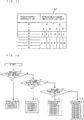
- Fig. 5 is a schematic diagram showing an example of the difficulty determination table 4 in Fig. 4 .
- the power supply difficulty SD in Fig. 5 is set stepwise from “0" to "8", and a higher number indicates a state where it is more difficult to supply power.
- the power supply difficulty SD is stored to be associated with the power supply information ED, the power use state EU, and the power generation state. For example, when the power supply information ED is categorized to "no problem", the amount of power generated by the solar power generation panel PV is categorized to "large amount”, and the power use state EU is categorized to "small amount”, the power supply difficulty SD is set at "0" at which there is no problem about power supply.
- the power supply information ED is categorized to "blackout”
- the power generation state of the solar power generation panel PV is categorized to "small amount”
- the power use state EU is categorized to "large amount”
- the power supply difficulty SD is set at "8" at which power supply is tight.
- the magnitudes of the power use state EU and the power generation state are categorized, for example, through thresholding.
- the power supply difficulty SD is distinguished into 9 levels of "0" to "8", but suffices to be able to be made different between the time of normal use and the time of emergency, and the number of levels suffices to be 2 or more.
- the controller 40 of the refrigerator 1A in Fig. 4 has a function of selecting and executing a power reduction control in accordance with the power supply difficulty SD determined by the centralized controller 2.
- the above-described power supply difficulty SD may be automatically transmitted from the centralized controller 2 via the network NW to the refrigerator 1A, or may be transmitted when the user operates the information terminal device 1E.
- a transmission method may be changed based on the level of the power supply difficulty SD such that, for example, in the case where the above-described power supply difficulty SD is "0" to "5", the centralized controller 2 automatically transmits the power supply difficulty SD to the plurality of electric devices 1A to 1C, and in the case where the power supply difficulty SD is "6" to "8", the power supply difficulty SD is transmitted through an operation of the user.
- the controller 40 includes reduction control setting means 41, a control setting table 42, and a device controller 43.
- the reduction control setting means 41 sets power reduction controls A to H to be executed from the control setting table 42 by using the power supply difficulty SD determined by the difficulty determination means 3.
- priorities of a plurality of the power reduction controls A to H are set in accordance with the power supply difficulty SD
- the reduction control setting means 41 sets the priorities of the plurality of the power reduction controls A to H in accordance with the power supply difficulty SD.
- Fig. 6 is a table indicating a ratio of a power consumption reduction effect and a burden on the user in each of the power reduction controls A to H
- Fig. 7 is a schematic diagram showing an example of the data structure of the control setting table 42.
- the power reduction controls A to H that reduce power use of the refrigerator 1A are set, and priority patterns each of which specifies an order in which the power reduction controls A to H are performed are stored to be associated with the power supply difficulty SD.
- priority patterns each of which specifies an order in which the power reduction controls A to H are performed are stored to be associated with the power supply difficulty SD.
- the power reduction control A (eco mode): eco mode is a power reduction control in which the use state of the refrigerator is determined based on an opening/closing sensor for each door and each temperature sensor, and if the frequency of use is low, the set temperature for each storage compartment is increased slightly (by about 2 K) to suppress wasted cooling to reduce the power consumption.
- the power reduction control A is a control in which the temperatures in the storage compartments 12 to 14 are increased, but the temperatures are increased based on the use state of the refrigerator at timing of a low frequency of use within a range where there is no influence on food storage, and thus there is almost no burden on the user.
- the power reduction control B (ice-making stop): ice-making stop is a power reduction control in which a function of automatically making ice is stopped to reduce cold air (capacity) required for making ice.
- the power reduction control B is a control in which it is impossible to automatically make ice, and a burden is put on the user who desires to use ice, but in a situation such as in winter where ice is not used, there is almost no burden on the user.
- refrigerator interior lighting device extinction is a power reduction control in which even if opening of the door 21 at the refrigerating compartment 11 is detected, the refrigerator interior lighting device 32 is not lit up.
- the power reduction control C is a control in which even if the door 21 at the refrigerating compartment 11 is opened, since the refrigerator interior lighting device 32 is not lit up, visibility in the refrigerating compartment 11 is decreased, and thus there is no influence on storage/cooling of food but a burden is put on the user.
- the power reduction control D rapid cooling avoidance
- rapid cooling avoidance is a power reduction control in which a rapid cooling function, which is settable in the operation panel 31, cannot be set.
- the power reduction control E rapid ice-making avoidance is a power reduction control in which a rapid ice-making function, which is settable in the operation panel 31, cannot be set.
- rapid ice-making is started, it is possible to shorten a time taken to make ice, by increasing the rotation speed of the compressor 33 and also decreasing the set temperature for the storage compartment 12 (ice-making compartment).
- the power consumption increases, and thus it is possible to prevent an increase in the power consumption by making the rapid ice-making unsettable.
- the above-described rapid cooling function and rapid ice-making function are additional merit functions, which are set in the operation panel 31.
- the power reduction control D or the power reduction control E are controls that put a burden on the user.
- defrost avoidance function is a power reduction control in which a heater (not shown) for melting frost on the cooler 34 is not energized.
- a heater not shown
- frost on the cooler 34 is normally melted by heating of the heater once every about 1 to 2 days.
- extra power for energizing the heater is consumed.
- the heater is not energized or the timing of energizing the heater is extended to once every 3 to 4 days, whereby it is possible to prevent an increase in the power consumption, although the cooling capacity decreases.
- the power reduction control G compressor rotation speed limit function is a power reduction control in which, of a plurality of rotation speeds of the compressor 33, the compressor 33 is prohibited from rotating at a high rotation speed.
- compressor rotation speed limit function is a power reduction control in which, of a plurality of rotation speeds of the compressor 33, the compressor 33 is prohibited from rotating at a high rotation speed.
- the upper limit of the rotation speed may be changed depending on the power supply difficulty. For example, when the power supply difficulty is low, the eighth level of the ten levels of the rotation speed may be the upper limit, and when the power supply difficulty is high, the sixth level of the ten levels may be the upper limit.
- the power reduction controls F and G are controls in which the cooling capacity is decreased. Even if the storage compartment is desired to be cooled, it may be impossible to cool the storage compartment to a target set temperature due to insufficient cooling capacity. Thus, a large burden is put on the user, for example, the storage life of food is shortened, and, in the worst case, frozen food is melted.
- the power reduction control H storage compartment temperature control
- storage compartment temperature shift-up is a power reduction control in which a set temperature for each of the storage compartments 12 to 14 is made higher than a normally set temperature. Since the power reduction control H is a control in which the set temperature for each of the storage compartments 12 to 14 is made higher than the normally set temperature, the power reduction control H is a control in which the burden on the user is very great, for example, the storage life of food is shortened and frozen food is melted. Normally, operation is performed at a set temperature corresponding to food stored in each compartment, such as a freezing compartment: about -18 degrees C and the refrigerating compartment: about 3 degrees C. By increasing the set temperature, the required cooling capacity is reduced, and thus it is possible to reduce the power consumption.
- the amount by which the set temperature is increased may be variable depending on the power supply difficulty SD.
- the set temperature may be changed, for example, when the power supply difficulty SD is low, the freezing compartment may be set at about -15 degrees C, and when the power supply difficulty SD is high, the freezing compartment may be set at about -12 degrees C.
- the temperature in each of the storage compartments 12 and 13 in which food is stored in a frozen state may be in a refrigerating temperature range (0 degrees C or higher), or a state where it is possible to store food without decaying the food, although the food cannot be stored in a frozen state, may be enabled to continue for a long period of time.
- the storage compartment for which the temperature shift-up is performed may be changed depending on the power supply difficulty SD, for example, when the power supply is low, the temperature shift-up may be performed only for the refrigerating compartment 11, and when the power supply difficulty SD is high, the temperature shift-up may be performed for all the storage compartments 12 to 14.
- the priorities are set such that when the power supply difficulty SD is low, the degree of reducing the power consumption is reduced to decrease the burden on the user.
- the priorities are set such that when the power supply difficulty SD is high, the burden on the user increases but the power consumption reduction effect is increased. Since the power reduction controls A to H for the refrigerator 1A are set in accordance with the power supply difficulty SD as described above, the power consumption is reduced without turning off the refrigerator 1A, and thus it is possible to handle the power supply difficulty without stopping storage or cooling of food.
- the power reduction controls A to H are an example of control for reducing the power consumption, and all the power reduction controls A to H may not be provided, or another control having a power consumption reduction effect may also be provided.
- the orders of the priorities are not limited to the orders in Fig. 7 as long as the priorities are set in accordance with the power supply difficulty SD.
- the device controller 43 in Fig. 4 performs the power reduction controls A to H, which are set by the reduction control setting means 41.
- the reduction control setting means 41 sets the power reduction controls A to H in the order of the priorities of the plurality of power reduction controls A to H, and the device controller 43 sequentially performs the set power reduction controls A to H.
- the device controller 43 initially and sequentially performs the power reduction control A set by the reduction control setting means 41. Then, for example, if the power consumption is reduced to a target amount at the time when the power reduction controls A to D have been performed, the device controller 43 does not execute the power reduction controls E to H.
- the device controller 43 has a function of detecting the power use state EU in the entire refrigerator 1A and outputting the power use state EU to the information transmission means 50.
- the information transmission means 50 transmits the power use state via the network NW to the centralized controller 2, and the centralized controller 2 determines the power supply difficulty SD based on the power use state EU transmitted from the refrigerator 1A and the power use state EU transmitted from each electric device such as the other air-conditioning device 1B and the information terminal device 1C (see Fig. 5 ).
- the controller 40 and the information transmission means 50 are separately provided, but as shown in Fig. 8 , the information transmission means 50 may be provided in the controller 40.
- the controller 40 and the information transmission means 50 are separate from each other as in Fig. 4 , by providing the information transmission means 50 to only the user who uses the power management system 100, it is possible to produce the controller 40 at low cost.
- the information transmission means 50 is configured such that a communication circuit is provided in the controller 40 as in Fig. 8 , the unit cost of the controller 40 increases, but it is possible to use the power management system 100 without mounting another component outside the refrigerator 1A.
- Fig. 9 is a flowchart showing an operation example of the power management system 100 and the refrigerator 1A in Fig. 4 , and the operation example of the power management system 100 and the refrigerator 1A will be described with reference to Figs. 1 to 9 .
- the power supply difficulty SD is calculated, for example, at every predetermined period in the centralized controller 2.
- the power supply difficulty SD is transmitted from the centralized controller 2 via the network NW to the refrigerator 1A.
- the reduction control setting means 41 of the controller 40 the priorities of the power reduction controls A to H are set in accordance with the power supply difficulty SD.
- step ST1 the priorities of the respective power reduction controls, which reduce the power consumption, are set as high: A ⁇ B ⁇ C ⁇ D ⁇ E ⁇ F ⁇ G ⁇ H: low (step ST2). If the power supply difficulty SD is equal to or higher than "1" and less than "3" (step ST3), the priorities are set as high: D ⁇ C ⁇ B ⁇ A ⁇ E ⁇ F ⁇ G -> H: low (step ST4). If the power supply difficulty is equal to or higher than "3" and less than "5" (step ST5), the priorities are set as high: F ⁇ E ⁇ D ⁇ C ⁇ B ⁇ A ⁇ G ⁇ H: low (step ST6).
- Fig. 9 shows the case where the determination is performed in the ascending order of the power supply difficulty SD, but as long as priorities corresponding to the power supply difficulty SD are set, the order thereof is any order.
- Fig. 10 is a functional block diagram showing Embodiment 2 of the power management system and the refrigerator of the present invention, and a controller 140 will be described with reference to Fig. 10 .
- the controller 140 in Fig. 10 the portions having the same configuration as the controller 40 in Fig. 4 are designated by the same reference signs, and the description thereof is omitted.
- Fig. 10 illustrates the case where the controller 40 and the information transmission means 50 are separately provided, but the information transmission means 50 may be provided in the controller 40 (see Fig. 8 ).
- the difference of the controller 140 in Fig. 10 from the controller 40 in Fig. 4 is that reduction control setting means 141 sets an executable control that is executable by using the power supply difficulty SD and a control setting table 142.
- the reduction control setting means 141 sets an executable control of the plurality of power reduction controls A to H by using the power supply difficulty SD and the control setting table 142, and the device controller 43 executes the power reduction control set by the reduction control setting means 141.
- Fig. 11 is a schematic diagram showing an example of the control setting table 142 in Fig. 10 .
- the contents of executable controls of the plurality of power reduction controls A to H are set for each power supply difficulty SD.
- setting is made such that the number of executable controls of the power reduction controls A to H increases as the power supply difficulty SD increases.
- Fig. 12 is a flowchart showing an operation example of the refrigerator 1A in Fig. 10 , and the operation example of the refrigerator 1A will be described with reference to Figs. 10 to 12 .
- the power supply difficulty SD is less than "1" (step ST1), it is determined that it is during normal use, and the executable power reduction controls are set as the "power reduction controls A and B" (step ST11).
- the executable power reduction controls are set as the "power reduction controls A, B, C, and D" (step ST12).
- step ST3 If the power supply difficulty SD is equal to or higher than "3" and less than "5" (step ST3), the executable power reduction controls are set as the "power reduction controls A, B, C, D, E, and F" (step ST13). If the power supply difficulty SD is equal to or higher than "5", all the power reduction controls A to H are set as being executable (step ST14).
- Fig. 12 illustrates the case where the power supply difficulty SD is categorized to "1", “3", and "5" for the executable reduction controls, but the executable reduction controls may be categorized to the time of normal use and the time of emergency or may be categorized to each power supply difficulty SD.
- which power reduction control is set as being executable at the time of the power supply difficulty SD is not limited to the case shown in Fig. 11 .
- the executable power reduction controls may be set as the "power reduction controls A, B, C, D, and E"
- the executable controls may be set based on balance between the power supply difficulty SD, the power reduction effect, and the degree of burden on the user.
Applications Claiming Priority (2)
| Application Number | Priority Date | Filing Date | Title |
|---|---|---|---|
| JP2013063938A JP6124642B2 (ja) | 2013-03-26 | 2013-03-26 | 電力管理システム及び冷蔵庫 |
| PCT/JP2014/052588 WO2014156312A1 (ja) | 2013-03-26 | 2014-02-04 | 電力管理システム及び冷蔵庫 |
Publications (3)
| Publication Number | Publication Date |
|---|---|
| EP2980947A1 EP2980947A1 (en) | 2016-02-03 |
| EP2980947A4 EP2980947A4 (en) | 2016-11-23 |
| EP2980947B1 true EP2980947B1 (en) | 2018-12-19 |
Family
ID=51623313
Family Applications (1)
| Application Number | Title | Priority Date | Filing Date |
|---|---|---|---|
| EP14776348.6A Not-in-force EP2980947B1 (en) | 2013-03-26 | 2014-02-04 | Power management system and refrigerator |
Country Status (6)
| Country | Link |
|---|---|
| US (1) | US10031543B2 (ja) |
| EP (1) | EP2980947B1 (ja) |
| JP (1) | JP6124642B2 (ja) |
| CN (1) | CN105122570B (ja) |
| SG (1) | SG11201505642RA (ja) |
| WO (1) | WO2014156312A1 (ja) |
Families Citing this family (6)
| Publication number | Priority date | Publication date | Assignee | Title |
|---|---|---|---|---|
| JP6125009B2 (ja) * | 2013-06-21 | 2017-05-10 | 三菱電機株式会社 | 電力管理システム及び冷蔵庫 |
| JP6410550B2 (ja) * | 2014-10-15 | 2018-10-24 | 三菱電機株式会社 | 冷蔵庫及びそれを備えたネットワークシステム |
| DE102014221318A1 (de) * | 2014-10-21 | 2016-04-21 | BSH Hausgeräte GmbH | Haushaltskältegerät mit Eisbereiter |
| JP6567034B2 (ja) * | 2017-12-27 | 2019-08-28 | 三菱電機株式会社 | 連携システム及び集中コントローラ |
| US11125493B2 (en) * | 2018-03-07 | 2021-09-21 | Carrier Corporation | Method and system for controlling use of a portable cooling container |
| JP7048446B2 (ja) * | 2018-07-31 | 2022-04-05 | 日立グローバルライフソリューションズ株式会社 | 制御ソフトウエアを書き換え可能な冷蔵庫 |
Family Cites Families (15)
| Publication number | Priority date | Publication date | Assignee | Title |
|---|---|---|---|---|
| JP3048839B2 (ja) * | 1994-05-12 | 2000-06-05 | 三洋電機株式会社 | ショーケースなどの運転制御装置 |
| JPH11296771A (ja) | 1998-04-13 | 1999-10-29 | Matsushita Electric Works Ltd | 消費電力監視機能を備えた住宅監視システム |
| CN2417439Y (zh) * | 2000-02-18 | 2001-01-31 | 李健 | 电冰箱智能节电保护器 |
| JP3945520B2 (ja) * | 2005-05-24 | 2007-07-18 | ダイキン工業株式会社 | 空調システム |
| ES2311360B1 (es) * | 2006-07-07 | 2009-12-02 | Bsh Electrodomesticos España, S.A. | Aparato electrodomestico. |
| JP4931656B2 (ja) * | 2007-03-19 | 2012-05-16 | 三洋電機株式会社 | 冷熱機器制御装置及び冷却機器の制御方法 |
| JP4551457B2 (ja) * | 2008-01-30 | 2010-09-29 | 日東工器株式会社 | 固定装置付き回転切削装置 |
| JP5167943B2 (ja) * | 2008-05-15 | 2013-03-21 | テンパール工業株式会社 | 住宅用分電盤 |
| US20100207728A1 (en) * | 2009-02-18 | 2010-08-19 | General Electric Corporation | Energy management |
| US20100217451A1 (en) * | 2009-02-24 | 2010-08-26 | Tetsuya Kouda | Energy usage control system and method |
| CN102513242B (zh) * | 2009-03-27 | 2016-01-20 | 三菱电机株式会社 | 雾化装置、设备、空气调节器以及电冰箱 |
| KR101637354B1 (ko) * | 2010-01-20 | 2016-07-07 | 엘지전자 주식회사 | 냉장고 및 그 제어방법 |
| CN102192625B (zh) * | 2010-03-10 | 2014-05-07 | 株式会社东芝 | 冰箱 |
| US8869546B2 (en) | 2010-11-03 | 2014-10-28 | General Electric Company | Refrigeration demand response recovery |
| KR20130014080A (ko) | 2011-07-29 | 2013-02-07 | 삼성전자주식회사 | 냉장고 및 그 제어 방법 |
-
2013
- 2013-03-26 JP JP2013063938A patent/JP6124642B2/ja active Active
-
2014
- 2014-02-04 CN CN201480018137.8A patent/CN105122570B/zh active Active
- 2014-02-04 SG SG11201505642RA patent/SG11201505642RA/en unknown
- 2014-02-04 EP EP14776348.6A patent/EP2980947B1/en not_active Not-in-force
- 2014-02-04 WO PCT/JP2014/052588 patent/WO2014156312A1/ja active Application Filing
- 2014-02-04 US US14/762,495 patent/US10031543B2/en active Active
Non-Patent Citations (1)
| Title |
|---|
| None * |
Also Published As
| Publication number | Publication date |
|---|---|
| US10031543B2 (en) | 2018-07-24 |
| CN105122570A (zh) | 2015-12-02 |
| EP2980947A1 (en) | 2016-02-03 |
| EP2980947A4 (en) | 2016-11-23 |
| SG11201505642RA (en) | 2015-09-29 |
| JP2014192937A (ja) | 2014-10-06 |
| US20150355657A1 (en) | 2015-12-10 |
| WO2014156312A1 (ja) | 2014-10-02 |
| CN105122570B (zh) | 2017-12-08 |
| JP6124642B2 (ja) | 2017-05-10 |
Similar Documents
| Publication | Publication Date | Title |
|---|---|---|
| EP2980947B1 (en) | Power management system and refrigerator | |
| CN101975498B (zh) | 冰箱 | |
| CN101929779B (zh) | 冰箱 | |
| JP6125009B2 (ja) | 電力管理システム及び冷蔵庫 | |
| CN103851875A (zh) | 一种冰箱冷藏室的控制方法 | |
| JP2011002141A (ja) | 冷蔵庫 | |
| CN106524648B (zh) | 一种冰箱及其控制方法 | |
| US8291718B2 (en) | DSM defrost during high demand | |
| CN105352262B (zh) | 风冷冰箱及其冷冻保护控制方法 | |
| JP5215367B2 (ja) | 冷蔵庫 | |
| CN202166258U (zh) | 一种双门冰箱 | |
| JP2011002142A (ja) | 冷蔵庫 | |
| CA2753806C (en) | Dsm defrost during high demand | |
| CN113834274B (zh) | 一种冰箱控制方法、装置及冰箱 | |
| JP5604543B2 (ja) | 冷蔵庫 | |
| JP2022140721A (ja) | 冷蔵庫、冷蔵庫制御方法、及び、冷蔵庫制御プログラム | |
| CN108351148B (zh) | 具有灵活的格室的制冷器具 | |
| JP2014224622A (ja) | 冷蔵庫 | |
| CN113758136A (zh) | 冰箱及其控制方法 | |
| WO2016046991A1 (ja) | 空調冷凍複合設備 | |
| CN104251596B (zh) | 用于直冷冰箱的化霜系统控制方法 | |
| CA2880051A1 (en) | Economizer target temperature shift during mechanical cooling | |
| CN109442785A (zh) | 制冷设备及控制方法 | |
| KR20120117704A (ko) | 정전 대비 냉동 냉장고 | |
| JP2014211272A (ja) | 冷蔵庫 |
Legal Events
| Date | Code | Title | Description |
|---|---|---|---|
| PUAI | Public reference made under article 153(3) epc to a published international application that has entered the european phase |
Free format text: ORIGINAL CODE: 0009012 |
|
| 17P | Request for examination filed |
Effective date: 20151007 |
|
| AK | Designated contracting states |
Kind code of ref document: A1 Designated state(s): AL AT BE BG CH CY CZ DE DK EE ES FI FR GB GR HR HU IE IS IT LI LT LU LV MC MK MT NL NO PL PT RO RS SE SI SK SM TR |
|
| AX | Request for extension of the european patent |
Extension state: BA ME |
|
| DAX | Request for extension of the european patent (deleted) | ||
| A4 | Supplementary search report drawn up and despatched |
Effective date: 20161026 |
|
| RIC1 | Information provided on ipc code assigned before grant |
Ipc: F25D 11/00 20060101ALI20161020BHEP Ipc: H02J 3/00 20060101AFI20161020BHEP Ipc: H02J 13/00 20060101ALI20161020BHEP |
|
| STAA | Information on the status of an ep patent application or granted ep patent |
Free format text: STATUS: EXAMINATION IS IN PROGRESS |
|
| 17Q | First examination report despatched |
Effective date: 20170908 |
|
| GRAP | Despatch of communication of intention to grant a patent |
Free format text: ORIGINAL CODE: EPIDOSNIGR1 |
|
| STAA | Information on the status of an ep patent application or granted ep patent |
Free format text: STATUS: GRANT OF PATENT IS INTENDED |
|
| INTG | Intention to grant announced |
Effective date: 20180709 |
|
| GRAS | Grant fee paid |
Free format text: ORIGINAL CODE: EPIDOSNIGR3 |
|
| GRAA | (expected) grant |
Free format text: ORIGINAL CODE: 0009210 |
|
| STAA | Information on the status of an ep patent application or granted ep patent |
Free format text: STATUS: THE PATENT HAS BEEN GRANTED |
|
| AK | Designated contracting states |
Kind code of ref document: B1 Designated state(s): AL AT BE BG CH CY CZ DE DK EE ES FI FR GB GR HR HU IE IS IT LI LT LU LV MC MK MT NL NO PL PT RO RS SE SI SK SM TR |
|
| REG | Reference to a national code |
Ref country code: GB Ref legal event code: FG4D |
|
| REG | Reference to a national code |
Ref country code: CH Ref legal event code: EP |
|
| REG | Reference to a national code |
Ref country code: IE Ref legal event code: FG4D |
|
| REG | Reference to a national code |
Ref country code: DE Ref legal event code: R096 Ref document number: 602014038265 Country of ref document: DE |
|
| REG | Reference to a national code |
Ref country code: AT Ref legal event code: REF Ref document number: 1079720 Country of ref document: AT Kind code of ref document: T Effective date: 20190115 |
|
| REG | Reference to a national code |
Ref country code: NL Ref legal event code: MP Effective date: 20181219 |
|
| PG25 | Lapsed in a contracting state [announced via postgrant information from national office to epo] |
Ref country code: FI Free format text: LAPSE BECAUSE OF FAILURE TO SUBMIT A TRANSLATION OF THE DESCRIPTION OR TO PAY THE FEE WITHIN THE PRESCRIBED TIME-LIMIT Effective date: 20181219 Ref country code: LV Free format text: LAPSE BECAUSE OF FAILURE TO SUBMIT A TRANSLATION OF THE DESCRIPTION OR TO PAY THE FEE WITHIN THE PRESCRIBED TIME-LIMIT Effective date: 20181219 Ref country code: NO Free format text: LAPSE BECAUSE OF FAILURE TO SUBMIT A TRANSLATION OF THE DESCRIPTION OR TO PAY THE FEE WITHIN THE PRESCRIBED TIME-LIMIT Effective date: 20190319 Ref country code: LT Free format text: LAPSE BECAUSE OF FAILURE TO SUBMIT A TRANSLATION OF THE DESCRIPTION OR TO PAY THE FEE WITHIN THE PRESCRIBED TIME-LIMIT Effective date: 20181219 Ref country code: HR Free format text: LAPSE BECAUSE OF FAILURE TO SUBMIT A TRANSLATION OF THE DESCRIPTION OR TO PAY THE FEE WITHIN THE PRESCRIBED TIME-LIMIT Effective date: 20181219 Ref country code: BG Free format text: LAPSE BECAUSE OF FAILURE TO SUBMIT A TRANSLATION OF THE DESCRIPTION OR TO PAY THE FEE WITHIN THE PRESCRIBED TIME-LIMIT Effective date: 20190319 |
|
| REG | Reference to a national code |
Ref country code: LT Ref legal event code: MG4D |
|
| REG | Reference to a national code |
Ref country code: AT Ref legal event code: MK05 Ref document number: 1079720 Country of ref document: AT Kind code of ref document: T Effective date: 20181219 |
|
| PG25 | Lapsed in a contracting state [announced via postgrant information from national office to epo] |
Ref country code: RS Free format text: LAPSE BECAUSE OF FAILURE TO SUBMIT A TRANSLATION OF THE DESCRIPTION OR TO PAY THE FEE WITHIN THE PRESCRIBED TIME-LIMIT Effective date: 20181219 Ref country code: GR Free format text: LAPSE BECAUSE OF FAILURE TO SUBMIT A TRANSLATION OF THE DESCRIPTION OR TO PAY THE FEE WITHIN THE PRESCRIBED TIME-LIMIT Effective date: 20190320 Ref country code: AL Free format text: LAPSE BECAUSE OF FAILURE TO SUBMIT A TRANSLATION OF THE DESCRIPTION OR TO PAY THE FEE WITHIN THE PRESCRIBED TIME-LIMIT Effective date: 20181219 Ref country code: SE Free format text: LAPSE BECAUSE OF FAILURE TO SUBMIT A TRANSLATION OF THE DESCRIPTION OR TO PAY THE FEE WITHIN THE PRESCRIBED TIME-LIMIT Effective date: 20181219 |
|
| PG25 | Lapsed in a contracting state [announced via postgrant information from national office to epo] |
Ref country code: NL Free format text: LAPSE BECAUSE OF FAILURE TO SUBMIT A TRANSLATION OF THE DESCRIPTION OR TO PAY THE FEE WITHIN THE PRESCRIBED TIME-LIMIT Effective date: 20181219 |
|
| PG25 | Lapsed in a contracting state [announced via postgrant information from national office to epo] |
Ref country code: PT Free format text: LAPSE BECAUSE OF FAILURE TO SUBMIT A TRANSLATION OF THE DESCRIPTION OR TO PAY THE FEE WITHIN THE PRESCRIBED TIME-LIMIT Effective date: 20190419 Ref country code: ES Free format text: LAPSE BECAUSE OF FAILURE TO SUBMIT A TRANSLATION OF THE DESCRIPTION OR TO PAY THE FEE WITHIN THE PRESCRIBED TIME-LIMIT Effective date: 20181219 Ref country code: CZ Free format text: LAPSE BECAUSE OF FAILURE TO SUBMIT A TRANSLATION OF THE DESCRIPTION OR TO PAY THE FEE WITHIN THE PRESCRIBED TIME-LIMIT Effective date: 20181219 Ref country code: PL Free format text: LAPSE BECAUSE OF FAILURE TO SUBMIT A TRANSLATION OF THE DESCRIPTION OR TO PAY THE FEE WITHIN THE PRESCRIBED TIME-LIMIT Effective date: 20181219 |
|
| PG25 | Lapsed in a contracting state [announced via postgrant information from national office to epo] |
Ref country code: EE Free format text: LAPSE BECAUSE OF FAILURE TO SUBMIT A TRANSLATION OF THE DESCRIPTION OR TO PAY THE FEE WITHIN THE PRESCRIBED TIME-LIMIT Effective date: 20181219 Ref country code: SM Free format text: LAPSE BECAUSE OF FAILURE TO SUBMIT A TRANSLATION OF THE DESCRIPTION OR TO PAY THE FEE WITHIN THE PRESCRIBED TIME-LIMIT Effective date: 20181219 Ref country code: SK Free format text: LAPSE BECAUSE OF FAILURE TO SUBMIT A TRANSLATION OF THE DESCRIPTION OR TO PAY THE FEE WITHIN THE PRESCRIBED TIME-LIMIT Effective date: 20181219 Ref country code: RO Free format text: LAPSE BECAUSE OF FAILURE TO SUBMIT A TRANSLATION OF THE DESCRIPTION OR TO PAY THE FEE WITHIN THE PRESCRIBED TIME-LIMIT Effective date: 20181219 Ref country code: IS Free format text: LAPSE BECAUSE OF FAILURE TO SUBMIT A TRANSLATION OF THE DESCRIPTION OR TO PAY THE FEE WITHIN THE PRESCRIBED TIME-LIMIT Effective date: 20190419 |
|
| REG | Reference to a national code |
Ref country code: DE Ref legal event code: R119 Ref document number: 602014038265 Country of ref document: DE |
|
| REG | Reference to a national code |
Ref country code: CH Ref legal event code: PL |
|
| PLBE | No opposition filed within time limit |
Free format text: ORIGINAL CODE: 0009261 |
|
| STAA | Information on the status of an ep patent application or granted ep patent |
Free format text: STATUS: NO OPPOSITION FILED WITHIN TIME LIMIT |
|
| PG25 | Lapsed in a contracting state [announced via postgrant information from national office to epo] |
Ref country code: LU Free format text: LAPSE BECAUSE OF NON-PAYMENT OF DUE FEES Effective date: 20190204 Ref country code: MC Free format text: LAPSE BECAUSE OF FAILURE TO SUBMIT A TRANSLATION OF THE DESCRIPTION OR TO PAY THE FEE WITHIN THE PRESCRIBED TIME-LIMIT Effective date: 20181219 Ref country code: AT Free format text: LAPSE BECAUSE OF FAILURE TO SUBMIT A TRANSLATION OF THE DESCRIPTION OR TO PAY THE FEE WITHIN THE PRESCRIBED TIME-LIMIT Effective date: 20181219 Ref country code: DK Free format text: LAPSE BECAUSE OF FAILURE TO SUBMIT A TRANSLATION OF THE DESCRIPTION OR TO PAY THE FEE WITHIN THE PRESCRIBED TIME-LIMIT Effective date: 20181219 |
|
| REG | Reference to a national code |
Ref country code: BE Ref legal event code: MM Effective date: 20190228 |
|
| 26N | No opposition filed |
Effective date: 20190920 |
|
| GBPC | Gb: european patent ceased through non-payment of renewal fee |
Effective date: 20190319 |
|
| REG | Reference to a national code |
Ref country code: IE Ref legal event code: MM4A |
|
| PG25 | Lapsed in a contracting state [announced via postgrant information from national office to epo] |
Ref country code: CH Free format text: LAPSE BECAUSE OF NON-PAYMENT OF DUE FEES Effective date: 20190228 Ref country code: LI Free format text: LAPSE BECAUSE OF NON-PAYMENT OF DUE FEES Effective date: 20190228 |
|
| PG25 | Lapsed in a contracting state [announced via postgrant information from national office to epo] |
Ref country code: IE Free format text: LAPSE BECAUSE OF NON-PAYMENT OF DUE FEES Effective date: 20190204 Ref country code: DE Free format text: LAPSE BECAUSE OF NON-PAYMENT OF DUE FEES Effective date: 20190903 Ref country code: GB Free format text: LAPSE BECAUSE OF NON-PAYMENT OF DUE FEES Effective date: 20190319 |
|
| PG25 | Lapsed in a contracting state [announced via postgrant information from national office to epo] |
Ref country code: SI Free format text: LAPSE BECAUSE OF FAILURE TO SUBMIT A TRANSLATION OF THE DESCRIPTION OR TO PAY THE FEE WITHIN THE PRESCRIBED TIME-LIMIT Effective date: 20181219 Ref country code: FR Free format text: LAPSE BECAUSE OF NON-PAYMENT OF DUE FEES Effective date: 20190219 Ref country code: BE Free format text: LAPSE BECAUSE OF NON-PAYMENT OF DUE FEES Effective date: 20190228 |
|
| PG25 | Lapsed in a contracting state [announced via postgrant information from national office to epo] |
Ref country code: TR Free format text: LAPSE BECAUSE OF FAILURE TO SUBMIT A TRANSLATION OF THE DESCRIPTION OR TO PAY THE FEE WITHIN THE PRESCRIBED TIME-LIMIT Effective date: 20181219 |
|
| PG25 | Lapsed in a contracting state [announced via postgrant information from national office to epo] |
Ref country code: MT Free format text: LAPSE BECAUSE OF NON-PAYMENT OF DUE FEES Effective date: 20190204 |
|
| PGFP | Annual fee paid to national office [announced via postgrant information from national office to epo] |
Ref country code: IT Payment date: 20210112 Year of fee payment: 8 |
|
| PG25 | Lapsed in a contracting state [announced via postgrant information from national office to epo] |
Ref country code: CY Free format text: LAPSE BECAUSE OF FAILURE TO SUBMIT A TRANSLATION OF THE DESCRIPTION OR TO PAY THE FEE WITHIN THE PRESCRIBED TIME-LIMIT Effective date: 20181219 |
|
| PG25 | Lapsed in a contracting state [announced via postgrant information from national office to epo] |
Ref country code: HU Free format text: LAPSE BECAUSE OF FAILURE TO SUBMIT A TRANSLATION OF THE DESCRIPTION OR TO PAY THE FEE WITHIN THE PRESCRIBED TIME-LIMIT; INVALID AB INITIO Effective date: 20140204 |
|
| PG25 | Lapsed in a contracting state [announced via postgrant information from national office to epo] |
Ref country code: MK Free format text: LAPSE BECAUSE OF FAILURE TO SUBMIT A TRANSLATION OF THE DESCRIPTION OR TO PAY THE FEE WITHIN THE PRESCRIBED TIME-LIMIT Effective date: 20181219 |
|
| PG25 | Lapsed in a contracting state [announced via postgrant information from national office to epo] |
Ref country code: IT Free format text: LAPSE BECAUSE OF NON-PAYMENT OF DUE FEES Effective date: 20220204 |