EP2980427A1 - Dispositif de palier lisse - Google Patents
Dispositif de palier lisse Download PDFInfo
- Publication number
- EP2980427A1 EP2980427A1 EP15178562.3A EP15178562A EP2980427A1 EP 2980427 A1 EP2980427 A1 EP 2980427A1 EP 15178562 A EP15178562 A EP 15178562A EP 2980427 A1 EP2980427 A1 EP 2980427A1
- Authority
- EP
- European Patent Office
- Prior art keywords
- bearing device
- sliding bearing
- intermediate element
- radial direction
- sliding
- Prior art date
- Legal status (The legal status is an assumption and is not a legal conclusion. Google has not performed a legal analysis and makes no representation as to the accuracy of the status listed.)
- Withdrawn
Links
Images


Classifications
-
- F—MECHANICAL ENGINEERING; LIGHTING; HEATING; WEAPONS; BLASTING
- F16—ENGINEERING ELEMENTS AND UNITS; GENERAL MEASURES FOR PRODUCING AND MAINTAINING EFFECTIVE FUNCTIONING OF MACHINES OR INSTALLATIONS; THERMAL INSULATION IN GENERAL
- F16C—SHAFTS; FLEXIBLE SHAFTS; ELEMENTS OR CRANKSHAFT MECHANISMS; ROTARY BODIES OTHER THAN GEARING ELEMENTS; BEARINGS
- F16C32/00—Bearings not otherwise provided for
- F16C32/06—Bearings not otherwise provided for with moving member supported by a fluid cushion formed, at least to a large extent, otherwise than by movement of the shaft, e.g. hydrostatic air-cushion bearings
- F16C32/0629—Bearings not otherwise provided for with moving member supported by a fluid cushion formed, at least to a large extent, otherwise than by movement of the shaft, e.g. hydrostatic air-cushion bearings supported by a liquid cushion, e.g. oil cushion
- F16C32/0633—Bearings not otherwise provided for with moving member supported by a fluid cushion formed, at least to a large extent, otherwise than by movement of the shaft, e.g. hydrostatic air-cushion bearings supported by a liquid cushion, e.g. oil cushion the liquid being retained in a gap
-
- F—MECHANICAL ENGINEERING; LIGHTING; HEATING; WEAPONS; BLASTING
- F16—ENGINEERING ELEMENTS AND UNITS; GENERAL MEASURES FOR PRODUCING AND MAINTAINING EFFECTIVE FUNCTIONING OF MACHINES OR INSTALLATIONS; THERMAL INSULATION IN GENERAL
- F16C—SHAFTS; FLEXIBLE SHAFTS; ELEMENTS OR CRANKSHAFT MECHANISMS; ROTARY BODIES OTHER THAN GEARING ELEMENTS; BEARINGS
- F16C17/00—Sliding-contact bearings for exclusively rotary movement
- F16C17/02—Sliding-contact bearings for exclusively rotary movement for radial load only
-
- F—MECHANICAL ENGINEERING; LIGHTING; HEATING; WEAPONS; BLASTING
- F16—ENGINEERING ELEMENTS AND UNITS; GENERAL MEASURES FOR PRODUCING AND MAINTAINING EFFECTIVE FUNCTIONING OF MACHINES OR INSTALLATIONS; THERMAL INSULATION IN GENERAL
- F16C—SHAFTS; FLEXIBLE SHAFTS; ELEMENTS OR CRANKSHAFT MECHANISMS; ROTARY BODIES OTHER THAN GEARING ELEMENTS; BEARINGS
- F16C17/00—Sliding-contact bearings for exclusively rotary movement
- F16C17/12—Sliding-contact bearings for exclusively rotary movement characterised by features not related to the direction of the load
- F16C17/18—Sliding-contact bearings for exclusively rotary movement characterised by features not related to the direction of the load with floating brasses or brushing, rotatable at a reduced speed
-
- F—MECHANICAL ENGINEERING; LIGHTING; HEATING; WEAPONS; BLASTING
- F16—ENGINEERING ELEMENTS AND UNITS; GENERAL MEASURES FOR PRODUCING AND MAINTAINING EFFECTIVE FUNCTIONING OF MACHINES OR INSTALLATIONS; THERMAL INSULATION IN GENERAL
- F16C—SHAFTS; FLEXIBLE SHAFTS; ELEMENTS OR CRANKSHAFT MECHANISMS; ROTARY BODIES OTHER THAN GEARING ELEMENTS; BEARINGS
- F16C17/00—Sliding-contact bearings for exclusively rotary movement
- F16C17/12—Sliding-contact bearings for exclusively rotary movement characterised by features not related to the direction of the load
- F16C17/24—Sliding-contact bearings for exclusively rotary movement characterised by features not related to the direction of the load with devices affected by abnormal or undesired positions, e.g. for preventing overheating, for safety
-
- F—MECHANICAL ENGINEERING; LIGHTING; HEATING; WEAPONS; BLASTING
- F16—ENGINEERING ELEMENTS AND UNITS; GENERAL MEASURES FOR PRODUCING AND MAINTAINING EFFECTIVE FUNCTIONING OF MACHINES OR INSTALLATIONS; THERMAL INSULATION IN GENERAL
- F16C—SHAFTS; FLEXIBLE SHAFTS; ELEMENTS OR CRANKSHAFT MECHANISMS; ROTARY BODIES OTHER THAN GEARING ELEMENTS; BEARINGS
- F16C32/00—Bearings not otherwise provided for
- F16C32/06—Bearings not otherwise provided for with moving member supported by a fluid cushion formed, at least to a large extent, otherwise than by movement of the shaft, e.g. hydrostatic air-cushion bearings
- F16C32/0681—Construction or mounting aspects of hydrostatic bearings, for exclusively rotary movement, related to the direction of load
- F16C32/0685—Construction or mounting aspects of hydrostatic bearings, for exclusively rotary movement, related to the direction of load for radial load only
- F16C32/0688—Construction or mounting aspects of hydrostatic bearings, for exclusively rotary movement, related to the direction of load for radial load only with floating bearing elements
-
- F—MECHANICAL ENGINEERING; LIGHTING; HEATING; WEAPONS; BLASTING
- F16—ENGINEERING ELEMENTS AND UNITS; GENERAL MEASURES FOR PRODUCING AND MAINTAINING EFFECTIVE FUNCTIONING OF MACHINES OR INSTALLATIONS; THERMAL INSULATION IN GENERAL
- F16C—SHAFTS; FLEXIBLE SHAFTS; ELEMENTS OR CRANKSHAFT MECHANISMS; ROTARY BODIES OTHER THAN GEARING ELEMENTS; BEARINGS
- F16C33/00—Parts of bearings; Special methods for making bearings or parts thereof
- F16C33/02—Parts of sliding-contact bearings
- F16C33/04—Brasses; Bushes; Linings
- F16C33/043—Sliding surface consisting mainly of ceramics, cermets or hard carbon, e.g. diamond like carbon [DLC]
-
- F—MECHANICAL ENGINEERING; LIGHTING; HEATING; WEAPONS; BLASTING
- F16—ENGINEERING ELEMENTS AND UNITS; GENERAL MEASURES FOR PRODUCING AND MAINTAINING EFFECTIVE FUNCTIONING OF MACHINES OR INSTALLATIONS; THERMAL INSULATION IN GENERAL
- F16C—SHAFTS; FLEXIBLE SHAFTS; ELEMENTS OR CRANKSHAFT MECHANISMS; ROTARY BODIES OTHER THAN GEARING ELEMENTS; BEARINGS
- F16C33/00—Parts of bearings; Special methods for making bearings or parts thereof
- F16C33/02—Parts of sliding-contact bearings
- F16C33/04—Brasses; Bushes; Linings
- F16C33/06—Sliding surface mainly made of metal
- F16C33/10—Construction relative to lubrication
- F16C33/1025—Construction relative to lubrication with liquid, e.g. oil, as lubricant
- F16C33/1045—Details of supply of the liquid to the bearing
- F16C33/1055—Details of supply of the liquid to the bearing from radial inside, e.g. via a passage through the shaft and/or inner sleeve
-
- F—MECHANICAL ENGINEERING; LIGHTING; HEATING; WEAPONS; BLASTING
- F16—ENGINEERING ELEMENTS AND UNITS; GENERAL MEASURES FOR PRODUCING AND MAINTAINING EFFECTIVE FUNCTIONING OF MACHINES OR INSTALLATIONS; THERMAL INSULATION IN GENERAL
- F16C—SHAFTS; FLEXIBLE SHAFTS; ELEMENTS OR CRANKSHAFT MECHANISMS; ROTARY BODIES OTHER THAN GEARING ELEMENTS; BEARINGS
- F16C17/00—Sliding-contact bearings for exclusively rotary movement
- F16C17/12—Sliding-contact bearings for exclusively rotary movement characterised by features not related to the direction of the load
- F16C17/22—Sliding-contact bearings for exclusively rotary movement characterised by features not related to the direction of the load with arrangements compensating for thermal expansion
-
- F—MECHANICAL ENGINEERING; LIGHTING; HEATING; WEAPONS; BLASTING
- F16—ENGINEERING ELEMENTS AND UNITS; GENERAL MEASURES FOR PRODUCING AND MAINTAINING EFFECTIVE FUNCTIONING OF MACHINES OR INSTALLATIONS; THERMAL INSULATION IN GENERAL
- F16C—SHAFTS; FLEXIBLE SHAFTS; ELEMENTS OR CRANKSHAFT MECHANISMS; ROTARY BODIES OTHER THAN GEARING ELEMENTS; BEARINGS
- F16C23/00—Bearings for exclusively rotary movement adjustable for aligning or positioning
- F16C23/02—Sliding-contact bearings
- F16C23/04—Sliding-contact bearings self-adjusting
- F16C23/043—Sliding-contact bearings self-adjusting with spherical surfaces, e.g. spherical plain bearings
- F16C23/045—Sliding-contact bearings self-adjusting with spherical surfaces, e.g. spherical plain bearings for radial load mainly, e.g. radial spherical plain bearings
-
- F—MECHANICAL ENGINEERING; LIGHTING; HEATING; WEAPONS; BLASTING
- F16—ENGINEERING ELEMENTS AND UNITS; GENERAL MEASURES FOR PRODUCING AND MAINTAINING EFFECTIVE FUNCTIONING OF MACHINES OR INSTALLATIONS; THERMAL INSULATION IN GENERAL
- F16C—SHAFTS; FLEXIBLE SHAFTS; ELEMENTS OR CRANKSHAFT MECHANISMS; ROTARY BODIES OTHER THAN GEARING ELEMENTS; BEARINGS
- F16C2361/00—Apparatus or articles in engineering in general
- F16C2361/61—Toothed gear systems, e.g. support of pinion shafts
-
- F—MECHANICAL ENGINEERING; LIGHTING; HEATING; WEAPONS; BLASTING
- F16—ENGINEERING ELEMENTS AND UNITS; GENERAL MEASURES FOR PRODUCING AND MAINTAINING EFFECTIVE FUNCTIONING OF MACHINES OR INSTALLATIONS; THERMAL INSULATION IN GENERAL
- F16C—SHAFTS; FLEXIBLE SHAFTS; ELEMENTS OR CRANKSHAFT MECHANISMS; ROTARY BODIES OTHER THAN GEARING ELEMENTS; BEARINGS
- F16C33/00—Parts of bearings; Special methods for making bearings or parts thereof
- F16C33/02—Parts of sliding-contact bearings
- F16C33/04—Brasses; Bushes; Linings
- F16C33/046—Brasses; Bushes; Linings divided or split, e.g. half-bearings or rolled sleeves
-
- F—MECHANICAL ENGINEERING; LIGHTING; HEATING; WEAPONS; BLASTING
- F16—ENGINEERING ELEMENTS AND UNITS; GENERAL MEASURES FOR PRODUCING AND MAINTAINING EFFECTIVE FUNCTIONING OF MACHINES OR INSTALLATIONS; THERMAL INSULATION IN GENERAL
- F16C—SHAFTS; FLEXIBLE SHAFTS; ELEMENTS OR CRANKSHAFT MECHANISMS; ROTARY BODIES OTHER THAN GEARING ELEMENTS; BEARINGS
- F16C33/00—Parts of bearings; Special methods for making bearings or parts thereof
- F16C33/02—Parts of sliding-contact bearings
- F16C33/04—Brasses; Bushes; Linings
- F16C33/06—Sliding surface mainly made of metal
- F16C33/10—Construction relative to lubrication
- F16C33/1025—Construction relative to lubrication with liquid, e.g. oil, as lubricant
- F16C33/106—Details of distribution or circulation inside the bearings, e.g. details of the bearing surfaces to affect flow or pressure of the liquid
- F16C33/1075—Wedges, e.g. ramps or lobes, for generating pressure
Definitions
- the invention relates to a sliding bearing device with an annular inner member, an annular intermediate member and an annular outer member according to the closer defined in the preamble of claim 1.
- Hydrodynamic slide bearing devices are used, for example, in a planetary gear set to support planet gears of the planetary gear set with respect to a planet carrier.
- Such plain bearing devices have an inner ring and an outer ring which are rotatable relative to each other, wherein during operation of the planetary gear set between the inner ring and the outer ring differential speeds may for example be in the range of 3,000 revolutions per minute to 4,000 revolutions per minute.
- the radial bearing is designed as an oil-filled floating bush bearing, wherein viewed in the radial direction between an inner rotating shaft and an outer bearing housing, a rotatable floating bushing is arranged, wherein a lubricating gap between the bearing housing and the floating bushing and a lubricating gap between the floating bush and the shaft are filled with lubricating oil.
- the floating bush bearing carries out speeds of up to 300,000 revolutions per minute, whereby instabilities in the axial position of the bearing can occur due to turbulences occurring in the oil layers.
- the shaft, the bearing housing and the floating bush are usually formed with metallic materials, in principle, even in such an embodiment at a starting movements, a contact between the elements of the floating bush bearing, d. H. between the shaft and the floating bush or between the floating bushing and the bearing housing, present.
- a contact between the elements of the floating bush bearing, d. H. between the shaft and the floating bush or between the floating bushing and the bearing housing present.
- micro-welds can form, which are then released again with an increase in the relative speed. This process can in turn lead to an undesirably large wear with corresponding disadvantages with respect to the life of the floating bush bearing.
- the present invention has for its object to provide a sliding bearing device available which has a simple way compared to known plain bearing devices increased life.
- the invention relates to a sliding bearing device having an inner annular inner element, at least one intermediate element comprising the inner element in the radial direction of the sliding bearing device and an annular outer element comprising the at least one intermediate element in the radial direction of the sliding bearing device, wherein the inner element is provided relative to the outer element and the at least one Intermediate member is rotatable relative to the inner member and relative to the outer member, and wherein in a ground state of the sliding bearing device, the inner member to the at least one intermediate member in the radial direction of the sliding bearing device and the at least one intermediate member to the outer member are spaced.
- the inner element and the outer element are designed with a metallic material and the at least one intermediate element with a non-metallic material.
- the sliding bearing device according to the invention has the advantage that wear in the region of the sliding bearing device over known plain bearing devices is greatly reduced in a structurally simple manner.
- This advantage is based on the fact that between the metallic inner element or the metallic outer element, which consist for example of steel, and the at least one non-metallic intermediate element or inlay, no micro-welds or greatly reduced micro-welds compared to known designs can occur, and thus a wear compared to known designs is greatly reduced.
- the sliding bearing device according to the invention by the provision of the annular intermediate element an improved compensation of a misalignment between an axis of the inner member and an axis of the outer member during operation of the sliding bearing device over conventionally known plain bearing devices only with an inner ring and an outer ring allows.
- the sliding bearing device according to the invention in this case has a comparable robustness as these plain bearing devices, whereas a sliding wear of the sliding bearing device according to the invention over the known plain bearing devices is substantially reduced.
- Micro-welds between the inner element or the outer element and the intermediate element can be reduced in a particularly effective manner or be prevented if the intermediate element is designed with a ceramic material.
- the inner element, the outer element and the at least one intermediate element in particular have a substantially cylindrical base body.
- a distance between the intermediate element and the inner element and a distance between the intermediate element and the outer element in the radial direction of the sliding bearing device is selected such that in the region of the at least one intermediate element in the operation of Slide bearing occurring tensile stresses are below a defined limit. Damage to the sliding bearing device during operation can thereby be prevented even with increasing operating temperatures of the sliding bearing device in a particularly secure manner.
- different expansion efforts of the inner element, the intermediate element and the outer element are taken into account via the structural design of the sliding bearing device according to the invention.
- a metallic inner element which expands more strongly at increasing operating temperatures than the ceramic intermediate element, does not produce any tensile stresses affecting the functionality of the intermediate element at increasing operating temperatures in the intermediate element.
- a surface of the at least one intermediate element facing the inner element and preferably a surface of the inner element facing the intermediate element and / or a surface of the at least one intermediate element facing the outer element and preferably a surface of the outer element facing the intermediate element in the direction of the central axis of the sliding bearing device are preferably corresponding to one another curved is executed or are, large misalignments of the inner member relative to the outer member in a simple manner wear compensated.
- the outer surface of the inner element, the inner surface of the intermediate element, the outer surface of the intermediate element and / or the inner surface of the outer member in a longitudinal section with respect to the central axis of the sliding bearing device viewed a constant radius of curvature.
- the cooperating surfaces of the inner member, the intermediate member and / or the outer member in the longitudinal sectional view of the sliding bearing device are part of a circle, wherein the radius of each mutually facing surfaces of the inner member and the intermediate member or the intermediate member and the outer member may differ from each other , A skew of a central axis of the inner member relative to a central axis of the outer element is particularly good and almost wear-free compensated.
- the surfaces correspond in particular to a section of a radially outer surface of a torus.
- the surfaces of the inner element, the outer element and the intermediate element are in particular each mirror-symmetrical to a center cross-sectional plane of the sliding bearing device.
- the intermediate element may be embodied spherically in the region of its surface facing the inner element and / or in the region of its surface facing the outer element.
- the intermediate element is executed in an advantageous embodiment of the invention in the circumferential direction of the sliding bearing device in several parts.
- the distances between the inner element and the outer element so dimensioned are that by heating and / or cooling of the inner member, the outer member and / or the intermediate member assembly is possible.
- a separating element is provided in the circumferential direction of the sliding bearing device between each two parts of the intermediate element.
- the parts of the intermediate element between the inner member and the outer member are introduced and brought in abutment with each other in the circumferential direction of the sliding bearing device with end faces in a circumferential direction of the slide member so that in a simple manner, all parts of the intermediate element between the inner member and the outer member can be introduced.
- one designed as a spacer, in particular formed with an elastic material separating element between adjacent in the circumferential direction of the sliding bearing device adjacent parts of the intermediate element can be introduced.
- the outer member in the axial direction of the sliding bearing device can be made at least two parts, wherein the parts of the outer member are connected to each other during assembly of the sliding bearing device.
- the parts of the outer element can be connected to one another, for example, by means of a welded connection, a screw connection, a riveted connection or the like.
- the slide bearing device according to the invention is preferably designed as a hydrodynamic or hydrostatic slide bearing device, wherein a hydraulic fluid is arranged in a space present in the radial direction of the slide bearing device between the inner element and the outer element.
- the intermediate element is in hydrodynamic operation of the sliding bearing device in particular completely surrounded by hydraulic fluid and between the inner element and the outer element floating.
- the distances between the surfaces of the inner element and the intermediate element or between the surfaces of the outer element and the intermediate element are preferably dimensioned such that tensile stresses in the region of the intermediate element are reliably avoided during operation of the sliding bearing devices and only compressive stresses act on the intermediate element.
- the risk of damage to the particular existing ceramic intermediate element is thus very low.
- the risk of undesirably high wear of the sliding bearing device at a lack of lubrication over known plain bearing devices only with an inner ring and an outer ring is greatly reduced.
- a closed hydraulic fluid space for the intermediate element is provided by preferably plate-shaped side elements which are for example firmly connected to the inner member or the outer member, wherein between the outer member or the inner member and the side member a sealing means may be provided.
- the plain bearing device according to the invention can be used, for example, in planetary gear sets for mounting planetary gears with respect to a planet carrier. Since a misalignment of the axes of the elements can be compensated particularly well with the sliding bearing device according to the invention, a one-sided storage of the planets is possible in which larger misalignments can occur.
- the sliding bearing device is preferably designed as a high-load sliding bearing device and performs revolutions in operation up to about 10,000 revolutions per minute, preferably in the order of 3,000 revolutions per minute to 4,000 revolutions per minute.
- Fig. 1 shows a highly simplified cross-sectional view of a particular hydrodynamic sliding bearing device 1 with respect to a central axis 3 of the sliding bearing device 1 in a ground state.
- the sliding bearing device 1 embodied as a high-load sliding bearing device has an outer annular element 5 or an inner ring 5 and an inner ring 5 which surrounds the inner element 5 with respect to a radial direction 7 of the sliding bearing device 1. having an outer ring.
- the ground state of the sliding bearing device 1 is understood to mean a state in which central axes of the inner member 5, the outer member 9 and the intermediate member 11 are congruent with the center axis 3 of the sliding bearing apparatus 1 and the sliding bearing apparatus 1 is in a load-free condition, in particular.
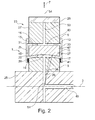
- Fig. 2 is a longitudinal sectional view of the sliding bearing device 1 with respect to the central axis 3 in the installed state of the sliding bearing device 1 can be seen.
- the sliding bearing device 1 is in this case in the range of only partially apparent planetary gear set 23 shown, wherein the inner member 5 of the sliding bearing device 1 rotatably with a planet carrier 25 of the planetary gear set 23 and the outer member 9 of the plain bearing device 1 rotatably connected to a planetary gear 27 of the planetary gear 23 and is made integral with this.
- the planetary gear 27 in turn acts via a toothing 29, for example, a double helical toothing, with a ring gear of the planetary gear 23, not shown in detail.
- the slide bearing device 1 has two annular disk-shaped lateral limiting elements 31, 33, which in the present case are each fixedly connected to the outer element 9 and extend in the radial direction 7 of the sliding bearing device 1 from a region of the outer element 9 into a region of the inner element 5 , Viewed in the direction of the central axis 3, the lateral limiting elements 31, 33 enclose the intermediate element 11 of the sliding bearing device 1 between them.
- the intermediate element 11 is floating in operation of the hydrodynamic sliding bearing device 1 in a hydraulic fluid, in particular oil, which is arranged in the sliding bearing device 1 in a space 43.
- the space 43 is formed by the outer surface 17 of the inner element 5, by the inner surface 13 of the outer element 9 and by the intermediate element 11 facing surfaces 45, 47 of the lateral limiting elements 31, 33.
- a sealing device 39, 41 is provided between the respective lateral boundary element 31, 33 and the inner element 5.
- the intermediate element 11 is spaced both to the outer surface 17 of the inner member 5, to the inner surface 13 of the outer member 9 and to the surfaces 45, 47 of the lateral limiting elements 31, 33, so that the intermediate member 11 is not in contact with the respective surfaces 13, 17, 45, 47 stands.
- the intermediate element 11 is arranged completely in the space 43, wherein between an intermediate element 11 facing inner surface 13 of the outer member 9 and an outer member 9 facing outer surface 15 of the intermediate member 11 in the unloaded state of the sliding bearing device 1, a distance 16 is present, the idle state of the sliding bearing device 1 in the circumferential direction 21 of the sliding bearing device 1 and in the direction of the central axis 3 of the sliding bearing device 1 is substantially constant. Likewise, between the intermediate element 11 facing an outer surface 17 of the inner member 5 and the inner member 5 facing inner surface 19 of the intermediate member 11 provided distance 20 in the idle state of the sliding bearing device 1 in the circumferential direction 21 of the sliding bearing device 1 and in the direction of the central axis 3 of the sliding bearing device 1 substantially constant and corresponds approximately to the distance 16.
- the inner element 5 and the outer element 9 here consist of a metallic material, for example steel, whereas the intermediate element 11 in the present case is made of a ceramic material. Due to the floating support of the intermediate element 11 and a corresponding choice of the distances 16, 20, it is reliably prevented that tensile stresses above a defined limit value act on the intermediate element 11 during operation of the sliding bearing device 1, which damage the intermediate element 11 consisting of ceramic can. During operation of the sliding bearing device 1, preferably only compressive stresses act on the intermediate element 11.
- the space 43 is presently supplied via oil or hydraulic lines 49, 51 with oil or hydraulic fluid, wherein oil via a running in the direction of the central axis 3 of the sliding bearing device 1 in the region of the planet carrier 25 oil line 49, in a radial direction 7 of the Slide bearing device 1 through the planet carrier 25 and the inner member 5 extending oil line 51 opens, the space 43 can be fed.
- oil is discharged by means of an additional oil pipe 53 in the radial direction 7 of the sliding bearing device 1 through the outer member 9 and the planetary gear 27 outwardly in the direction of the toothing 29.
- both the outer surface 17 of the inner element 5 and the inner surface 19 of the intermediate element 11 are curved or curved, wherein in each case a lateral limiting element 31, 33 facing portions of the surfaces 17, 19 a smaller distance from a central axis 3 of the sliding bearing device. 1 as a relative to the lateral boundary elements 31, 33 middle region of the surfaces 17, 19 has.
- the surfaces 17, 19 are in the in Fig. 2 shown sectional view in each case part of a circular area, the center of which lie in particular on the central axis 3 of the sliding bearing device 1, wherein the outer surface 17 of the inner member 5 associated radius 36 is smaller than a the inner surface 19 of the intermediate member 11 associated radius 38.
- the surfaces 17, 19 in this case are designed symmetrically to a central cross-sectional plane 54 of the sliding bearing device 1, in the present case, the oil lines 51 and 53 are.
- the outer surface 15 of the intermediate element 11 and the inner surface 13 of the outer element 9 are part of a cylindrical surface whose central axis in the basic state of the sliding bearing device corresponds to the central axis 3 of the sliding bearing device 1.
- the surfaces 13, 15 can also be curved or bent in a manner comparable to the surfaces 17, 19.
- the curvature of the surfaces 17, 19 and the distances 16, 20 are also coordinated so that the integrally running intermediate element 11 for mounting the sliding bearing device 1 in a simple manner between the inner member 5 and the outer member 9 is inserted.
- the shown robust slide bearing device 1 is designed by way of example for revolutions in the order of, for example, 3,000 revolutions per minute to 4,000 revolutions per minute, with a sliding wear in the area of the sliding bearing device 1 being very small.
- the risk of heavy wear in the region of the sliding bearing device 1 is greatly reduced with a lack of lubrication compared to known designs.
- a slide bearing device 55 is shown, which substantially corresponds to the sliding bearing device 1.
- an intermediate member 57 of the sliding bearing device 55 is not integral, but in the circumferential direction 21 of the sliding bearing device 55 made of several parts.
- the intermediate element 57 has three substantially identical parts 59, 61, 63, wherein in an alternative embodiment of the invention, a different number of parts, in particular a plurality, may be provided.
- the parts 59, 61, 63 are first introduced into the space 43 between the inner element 5 and the outer element 9. If the parts 59, 61, 63 in this case in the circumferential direction 21 of the slide bearing device 55 are each brought into abutment with each other, an introduction, in particular of the last part 59, 61 and 63 of the intermediate member 57 is particularly easy. Subsequently, between adjacent parts 59, 61, 63 of the intermediate member 57 respectively as spacers 65, 67, 69 executed separating elements are introduced. The spacers 65, 67, 69 and the parts 59, 61, 63 of the intermediate element 57 are arranged distributed in the assembled state of the sliding bearing device 55 evenly over the circumference of the sliding bearing device 55.
- Fig. 4 a further plain bearing device 71 is shown, which substantially corresponds to the sliding bearing device 1, so that in the following only the differences between these embodiments will be discussed.
- Both the outer surface 17 of the inner member 5 and the inner surface 19 of the intermediate member 11 are in the sliding bearing device 71 part of a cylindrical surface whose central axis corresponds in the ground state of the sliding bearing device 71 of the central axis 3 of the sliding bearing device 71.
- the surfaces 13, 15 of the outer member 9 and the intermediate member 11 are curved or bent, each of the lateral limiting element 31, 33 facing portions of the surfaces 13, 15 a smaller distance to a central axis 3 of the sliding bearing device 71 as a respect to the lateral Limiting elements 31, 33 middle region of the surfaces 13, 15 have.
- the surfaces 13, 15 are in the in Fig. 4 sectional view shown in each case part of a circular area whose center is located in particular on the central axis 3 of the sliding bearing device 1.
- a radius 73 assigned to the outer surface 15 of the intermediate element 11 is smaller than a radius 75 assigned to the inner surface 13 of the outer element 9, the surfaces 13, 15 being configured symmetrically to the central cross-sectional plane 54 of the sliding bearing device 71.
- the surfaces 17, 19 can in turn be designed to curve or bend in a manner corresponding to the surfaces 17, 19.
- the outer element 9 is designed in two parts in the axial direction of the sliding bearing device 71 and has a first part 77 and a second part 79.
- the Parts 77, 79 of the outer member 9 presently have an approximately identical length in the axial direction of the slide bearing device 71 and are arranged in the assembly of the slide bearing device 71 in the axial direction viewed from opposite sides to the intermediate member 11.
- the parts 77, 79 of the outer element 9 are in the present case connected to one another via a welded connection, but alternatively or in addition to this, they can also be connected to one another via a screw connection, a rivet connection or the like.
Applications Claiming Priority (1)
| Application Number | Priority Date | Filing Date | Title |
|---|---|---|---|
| DE102014110907.4A DE102014110907A1 (de) | 2014-07-31 | 2014-07-31 | Gleitlagervorrichtung |
Publications (1)
| Publication Number | Publication Date |
|---|---|
| EP2980427A1 true EP2980427A1 (fr) | 2016-02-03 |
Family
ID=53835886
Family Applications (1)
| Application Number | Title | Priority Date | Filing Date |
|---|---|---|---|
| EP15178562.3A Withdrawn EP2980427A1 (fr) | 2014-07-31 | 2015-07-28 | Dispositif de palier lisse |
Country Status (3)
| Country | Link |
|---|---|
| US (1) | US9470265B2 (fr) |
| EP (1) | EP2980427A1 (fr) |
| DE (1) | DE102014110907A1 (fr) |
Cited By (3)
| Publication number | Priority date | Publication date | Assignee | Title |
|---|---|---|---|---|
| CN108468573A (zh) * | 2018-05-16 | 2018-08-31 | 中车大连机车研究所有限公司 | 轴流式涡轮增压器双浮环推力轴承结构 |
| EP3404294A1 (fr) * | 2017-05-19 | 2018-11-21 | Renk Aktiengesellschaft | Engrenage, en particulier pour générateurs éoliens |
| WO2019063230A1 (fr) * | 2017-09-28 | 2019-04-04 | Zf Friedrichshafen Ag | Palier lisse doté d'une douille frittée à montage flottant et étage planétaire comportant un tel palier lisse |
Families Citing this family (6)
| Publication number | Priority date | Publication date | Assignee | Title |
|---|---|---|---|---|
| DE102013221265A1 (de) * | 2013-10-21 | 2015-05-07 | Schaeffler Technologies Gmbh & Co. Kg | Planetenradlageranordnung |
| JP2016169861A (ja) * | 2015-03-13 | 2016-09-23 | キヤノン株式会社 | 摺動部材、摺動機構及び搬送装置 |
| DE102017222901A1 (de) * | 2017-12-15 | 2019-06-19 | Zf Friedrichshafen Ag | Planetengetriebestufe mit einer Gleitlageranordnung, insbesondere für eine Planetenradlagerung in einem Windkraftgetriebe |
| US10584741B2 (en) * | 2018-04-10 | 2020-03-10 | Terry Michael Brown | Bottom bearing |
| DE102019218116A1 (de) * | 2019-11-25 | 2021-05-27 | Zf Friedrichshafen Ag | Schwimmbuchse mit konvexer Gleitfläche |
| DE102020122430A1 (de) | 2020-08-27 | 2022-03-03 | Rolls-Royce Deutschland Ltd & Co Kg | Planetengetriebe |
Citations (11)
| Publication number | Priority date | Publication date | Assignee | Title |
|---|---|---|---|---|
| FR915604A (fr) * | 1944-09-11 | 1946-11-13 | Perfectionnements apportés aux paliers ou coussinets | |
| FR961631A (fr) * | 1950-05-16 | |||
| GB1174628A (en) * | 1966-06-21 | 1969-12-17 | Skf Svenska Kullagerfab Ab | Improvements in or relating to Reversible Bearings of Spiral or Helical Groove Type |
| DE1913365A1 (de) * | 1969-03-15 | 1970-09-24 | Koepke Dr Ing Guenter | Differentialgleitelement |
| US3544177A (en) * | 1968-03-19 | 1970-12-01 | Skf Ind Inc | Elastohydrodynamic sliding bearings |
| US3920293A (en) * | 1974-04-23 | 1975-11-18 | Hirokazu Takeuchi | Bearing made of plastics |
| DE2837938A1 (de) * | 1978-08-31 | 1980-03-20 | Licentia Gmbh | Waeschebehandlungsmaschine |
| WO1995022011A1 (fr) * | 1994-02-08 | 1995-08-17 | Plastic Bearings & Housings Australasia Pty. Ltd. | Palier lisse |
| US5820270A (en) * | 1997-05-23 | 1998-10-13 | Totall Attachments Inc. | Slewing turntable bearing |
| DE102012202341A1 (de) | 2012-02-16 | 2013-08-22 | Continental Automotive Gmbh | Radiallager für einen Abgasturbolader |
| US8616772B1 (en) * | 2013-03-15 | 2013-12-31 | Little Engine, LLC | Conformal wear-resistant bearing assembly |
Family Cites Families (12)
| Publication number | Priority date | Publication date | Assignee | Title |
|---|---|---|---|---|
| US2596202A (en) * | 1949-09-13 | 1952-05-13 | Frank B Bolte | Self-aligning controlled friction bearing |
| DE1913365U (de) | 1964-11-18 | 1965-04-08 | Franz Wagner | Sicherheitsanordnung fuer grubenlokomotiven. |
| DE2558678C2 (de) * | 1975-12-24 | 1982-06-09 | FAG Kugelfischer Georg Schäfer & Co, 8720 Schweinfurt | Hydrostatisches Radiallager |
| US4204718A (en) * | 1978-12-11 | 1980-05-27 | The Garrett Corporation | Bearing assembly |
| US4318572A (en) * | 1980-01-11 | 1982-03-09 | Mts Systems Corporation | Tension-compression swivel joint with hydraulic force reaction |
| DE3014645C2 (de) * | 1980-04-16 | 1982-12-02 | MTU Motoren- und Turbinen-Union München GmbH, 8000 München | Metall-Keramik-Bauteil und Verfahren zu seiner Herstellung |
| DE3635837A1 (de) * | 1986-10-22 | 1988-04-28 | Krupp Gmbh | Gleitlager mit dehnungsausgleichselementen |
| US5219231A (en) * | 1987-10-02 | 1993-06-15 | Plastic Bearing Housing Australiasia Pty Ltd. | Split race bearing assemblies |
| US20040022464A1 (en) * | 2002-08-05 | 2004-02-05 | Alan Schinazi | Self-aligning bearing assembly with intermediate compliant spherical load ring |
| DE202007000609U1 (de) * | 2007-01-10 | 2008-05-21 | Ask-Kugellagerfabrik Artur Seyfert Gmbh | Gleitelement für Lager, insbesondere für Gelenklager |
| US8075190B1 (en) * | 2010-09-16 | 2011-12-13 | Vestas Wind Systems A/S | Spherical plain bearing pocket arrangement and wind turbine having such a spherical plain bearing |
| DE102011121562A1 (de) * | 2011-12-20 | 2013-06-20 | Robert Bosch Gmbh | Gleitlager |
-
2014
- 2014-07-31 DE DE102014110907.4A patent/DE102014110907A1/de not_active Withdrawn
-
2015
- 2015-07-28 EP EP15178562.3A patent/EP2980427A1/fr not_active Withdrawn
- 2015-07-29 US US14/812,600 patent/US9470265B2/en active Active
Patent Citations (11)
| Publication number | Priority date | Publication date | Assignee | Title |
|---|---|---|---|---|
| FR961631A (fr) * | 1950-05-16 | |||
| FR915604A (fr) * | 1944-09-11 | 1946-11-13 | Perfectionnements apportés aux paliers ou coussinets | |
| GB1174628A (en) * | 1966-06-21 | 1969-12-17 | Skf Svenska Kullagerfab Ab | Improvements in or relating to Reversible Bearings of Spiral or Helical Groove Type |
| US3544177A (en) * | 1968-03-19 | 1970-12-01 | Skf Ind Inc | Elastohydrodynamic sliding bearings |
| DE1913365A1 (de) * | 1969-03-15 | 1970-09-24 | Koepke Dr Ing Guenter | Differentialgleitelement |
| US3920293A (en) * | 1974-04-23 | 1975-11-18 | Hirokazu Takeuchi | Bearing made of plastics |
| DE2837938A1 (de) * | 1978-08-31 | 1980-03-20 | Licentia Gmbh | Waeschebehandlungsmaschine |
| WO1995022011A1 (fr) * | 1994-02-08 | 1995-08-17 | Plastic Bearings & Housings Australasia Pty. Ltd. | Palier lisse |
| US5820270A (en) * | 1997-05-23 | 1998-10-13 | Totall Attachments Inc. | Slewing turntable bearing |
| DE102012202341A1 (de) | 2012-02-16 | 2013-08-22 | Continental Automotive Gmbh | Radiallager für einen Abgasturbolader |
| US8616772B1 (en) * | 2013-03-15 | 2013-12-31 | Little Engine, LLC | Conformal wear-resistant bearing assembly |
Cited By (6)
| Publication number | Priority date | Publication date | Assignee | Title |
|---|---|---|---|---|
| EP3404294A1 (fr) * | 2017-05-19 | 2018-11-21 | Renk Aktiengesellschaft | Engrenage, en particulier pour générateurs éoliens |
| US10731730B2 (en) | 2017-05-19 | 2020-08-04 | Renk Aktiengesellschaft | Transmission in particular for wind power generators |
| TWI756412B (zh) * | 2017-05-19 | 2022-03-01 | 德商輪克有限責任公司 | 用於風力發電機之傳動裝置 |
| WO2019063230A1 (fr) * | 2017-09-28 | 2019-04-04 | Zf Friedrichshafen Ag | Palier lisse doté d'une douille frittée à montage flottant et étage planétaire comportant un tel palier lisse |
| CN108468573A (zh) * | 2018-05-16 | 2018-08-31 | 中车大连机车研究所有限公司 | 轴流式涡轮增压器双浮环推力轴承结构 |
| CN108468573B (zh) * | 2018-05-16 | 2023-10-13 | 中国国家铁路集团有限公司 | 轴流式涡轮增压器双浮环推力轴承结构 |
Also Published As
| Publication number | Publication date |
|---|---|
| US9470265B2 (en) | 2016-10-18 |
| DE102014110907A1 (de) | 2016-02-04 |
| US20160032968A1 (en) | 2016-02-04 |
Similar Documents
| Publication | Publication Date | Title |
|---|---|---|
| EP2980427A1 (fr) | Dispositif de palier lisse | |
| EP3405689B1 (fr) | Ensemble de palier | |
| DE102010054905A1 (de) | Lagereinheit für einen Turbolader | |
| EP0227991A2 (fr) | Palier dynamique à air | |
| EP2715162B2 (fr) | Couronne d'orientation | |
| DE102018104685A1 (de) | Antriebsvorrichtung mit einem Elektromotor und einem Getriebe | |
| EP3271597A1 (fr) | Turbocompresseur à gaz d'échappement | |
| DE112018005332B4 (de) | Zahnradvorrichtung des biegeeingriffstyps | |
| DE102016214018A1 (de) | Lageranordnung, insbesondere für eine Strömungsmaschine, und Strömungsmaschine mit einer derartigen Lageranordnung | |
| EP2547925B1 (fr) | Coquille de coussinet lisse | |
| DE10306926B4 (de) | Axiallager | |
| DE102016115874B4 (de) | Lagervorrichtung für eine Kurbelwelle eines Verbrennungsmotors | |
| EP3762624B1 (fr) | Turbocompresseur à gaz d'échappement doté d'un palier lisse hydrodynamique ou arrangement de palier doté d'un palier lisse hydrodynamique | |
| DE112015005799T5 (de) | Ventilvorrichtung | |
| EP3434917A1 (fr) | Dispositif palier destiné au logement d'un arbre de transmission | |
| DE112018006765T5 (de) | Turbolader | |
| EP1717466A2 (fr) | Palier lisse avec un entrefer divergeant dans la zone d'extrémité | |
| WO2015106743A1 (fr) | Mecanisme de direction | |
| DE102005012083A1 (de) | Lageranordnung, insbesondere für Wälzlager oder Gleitlager | |
| EP2511551A2 (fr) | Palier à roulement | |
| DE202010016129U1 (de) | Dichtung und Wälzlager, das eine solche Dichtung aufweist | |
| DE102018130706A1 (de) | Abgasturbolader mit einem hydrodynamischen Gleitlager oder hydrodynamisches Gleitlager | |
| DE102014209647A1 (de) | Kugellager für einen Turbolader | |
| DE102017206686A1 (de) | Lageranordnung zur Lagerung einer Getriebewelle | |
| WO2021259414A1 (fr) | Palier lisse à contact oblique |
Legal Events
| Date | Code | Title | Description |
|---|---|---|---|
| PUAI | Public reference made under article 153(3) epc to a published international application that has entered the european phase |
Free format text: ORIGINAL CODE: 0009012 |
|
| AK | Designated contracting states |
Kind code of ref document: A1 Designated state(s): AL AT BE BG CH CY CZ DE DK EE ES FI FR GB GR HR HU IE IS IT LI LT LU LV MC MK MT NL NO PL PT RO RS SE SI SK SM TR |
|
| AX | Request for extension of the european patent |
Extension state: BA ME |
|
| 17P | Request for examination filed |
Effective date: 20160513 |
|
| RBV | Designated contracting states (corrected) |
Designated state(s): AL AT BE BG CH CY CZ DE DK EE ES FI FR GB GR HR HU IE IS IT LI LT LU LV MC MK MT NL NO PL PT RO RS SE SI SK SM TR |
|
| STAA | Information on the status of an ep patent application or granted ep patent |
Free format text: STATUS: EXAMINATION IS IN PROGRESS |
|
| 17Q | First examination report despatched |
Effective date: 20190204 |
|
| STAA | Information on the status of an ep patent application or granted ep patent |
Free format text: STATUS: EXAMINATION IS IN PROGRESS |
|
| STAA | Information on the status of an ep patent application or granted ep patent |
Free format text: STATUS: THE APPLICATION IS DEEMED TO BE WITHDRAWN |
|
| 18D | Application deemed to be withdrawn |
Effective date: 20210202 |