EP2980425A1 - Agencement de fixation pour rails de retenue en forme de c et kit - Google Patents
Agencement de fixation pour rails de retenue en forme de c et kit Download PDFInfo
- Publication number
- EP2980425A1 EP2980425A1 EP15174328.3A EP15174328A EP2980425A1 EP 2980425 A1 EP2980425 A1 EP 2980425A1 EP 15174328 A EP15174328 A EP 15174328A EP 2980425 A1 EP2980425 A1 EP 2980425A1
- Authority
- EP
- European Patent Office
- Prior art keywords
- sliding nut
- screw
- retaining
- fastening arrangement
- arrangement according
- Prior art date
- Legal status (The legal status is an assumption and is not a legal conclusion. Google has not performed a legal analysis and makes no representation as to the accuracy of the status listed.)
- Granted
Links
- 125000006850 spacer group Chemical group 0.000 claims abstract description 20
- 239000000463 material Substances 0.000 claims description 4
- 238000010276 construction Methods 0.000 description 2
- 230000000694 effects Effects 0.000 description 2
- 238000003780 insertion Methods 0.000 description 2
- 230000037431 insertion Effects 0.000 description 2
- 230000000712 assembly Effects 0.000 description 1
- 238000000429 assembly Methods 0.000 description 1
- 230000015572 biosynthetic process Effects 0.000 description 1
- 230000006835 compression Effects 0.000 description 1
- 238000007906 compression Methods 0.000 description 1
- 230000008878 coupling Effects 0.000 description 1
- 238000010168 coupling process Methods 0.000 description 1
- 238000005859 coupling reaction Methods 0.000 description 1
- 238000002347 injection Methods 0.000 description 1
- 239000007924 injection Substances 0.000 description 1
- 238000004519 manufacturing process Methods 0.000 description 1
- 230000013011 mating Effects 0.000 description 1
Images


Classifications
-
- F—MECHANICAL ENGINEERING; LIGHTING; HEATING; WEAPONS; BLASTING
- F16—ENGINEERING ELEMENTS AND UNITS; GENERAL MEASURES FOR PRODUCING AND MAINTAINING EFFECTIVE FUNCTIONING OF MACHINES OR INSTALLATIONS; THERMAL INSULATION IN GENERAL
- F16B—DEVICES FOR FASTENING OR SECURING CONSTRUCTIONAL ELEMENTS OR MACHINE PARTS TOGETHER, e.g. NAILS, BOLTS, CIRCLIPS, CLAMPS, CLIPS OR WEDGES; JOINTS OR JOINTING
- F16B7/00—Connections of rods or tubes, e.g. of non-circular section, mutually, including resilient connections
- F16B7/04—Clamping or clipping connections
- F16B7/044—Clamping or clipping connections for rods or tubes being in angled relationship
- F16B7/0446—Clamping or clipping connections for rods or tubes being in angled relationship for tubes using the innerside thereof
- F16B7/0473—Clamping or clipping connections for rods or tubes being in angled relationship for tubes using the innerside thereof with hook-like parts gripping, e.g. by expanding, behind the flanges of a profile
-
- F—MECHANICAL ENGINEERING; LIGHTING; HEATING; WEAPONS; BLASTING
- F16—ENGINEERING ELEMENTS AND UNITS; GENERAL MEASURES FOR PRODUCING AND MAINTAINING EFFECTIVE FUNCTIONING OF MACHINES OR INSTALLATIONS; THERMAL INSULATION IN GENERAL
- F16B—DEVICES FOR FASTENING OR SECURING CONSTRUCTIONAL ELEMENTS OR MACHINE PARTS TOGETHER, e.g. NAILS, BOLTS, CIRCLIPS, CLAMPS, CLIPS OR WEDGES; JOINTS OR JOINTING
- F16B37/00—Nuts or like thread-engaging members
- F16B37/04—Devices for fastening nuts to surfaces, e.g. sheets, plates
- F16B37/045—Devices for fastening nuts to surfaces, e.g. sheets, plates specially adapted for fastening in channels, e.g. sliding bolts, channel nuts
- F16B37/046—Devices for fastening nuts to surfaces, e.g. sheets, plates specially adapted for fastening in channels, e.g. sliding bolts, channel nuts with resilient means for urging the nut inside the channel
Definitions
- the invention relates to a fastening arrangement for C-shaped retaining rails with a screw and a sliding nut, wherein a threaded portion of the screw is at least partially screwed into a threaded bore of the sliding nut, arranged between a screw head of the screw and the sliding nut holding disc and a between the retaining disk and the Sliding nut arranged positioning.
- the invention also relates to a kit comprising at least one fastening arrangement according to the invention, at least one C-shaped retaining rail and at least one mounting bracket.
- a fastening arrangement for C-shaped retaining rails which has a screw, a sliding nut and arranged between the screw and the sliding nut holding disc.
- a biasing member is arranged, which has two plastic parts and a coil spring arranged between the plastic parts.
- the two plastic parts are telescopically telescoping and ensure that the sliding nut is held in a fixed position to the retaining disc, and thus can be rotated by 90 ° together with the retaining disc after insertion into the C-shaped support rail.
- EP 1 201 941 A2 is another mounting arrangement for C-shaped support rails with a screw and a sliding nut known. Between a head of the screw and the sliding nut a retaining disc is arranged. A diaphragm spring or coil spring between the head of the screw and the retaining washer pushes apart the retaining washer and the screw head and thereby pulls the sliding nut into an abutment position against the retaining washer. To insert the mounting arrangement in a C-shaped retaining rail, the screw is pressed relative to the retaining plate down, so that then the screw can be rotated together with the sliding nut by 90 °.
- the spring retracts the sliding nut in the direction of the retaining washer and a coupling provided between the retaining washer and the sliding nut snaps into place. In this position, the screw can then be rotated relative to the sliding nut and the mounting arrangement can be screwed.
- a fastening arrangement for C-shaped support rails with a screw and a sliding nut wherein a threaded portion of the screw is at least partially screwed into a threaded bore of the sliding nut, wherein a arranged between a screw head of the screw and the sliding nut holding disc and a positioning member are provided in which the positioning component has a spacer section arranged between the retaining disk and the sliding nut and a prestressing section acting on a lower side of the sliding nut facing away from the screw head.
- the positioning member engages around the sliding nut and engages the underside of the sliding nut.
- the positioning can be made very simple and yet it is ensured that the retaining disk and the sliding nut at rest have a constant distance from each other and then can be moved away from each other by pressing the screw head to the sliding nut then within the C-shaped support rail by 90 ° to be able to turn.
- the spacer portion and the biasing portion are connected by means of two webs, which bear against in particular opposite longitudinal sides of the sliding nut.
- the sliding nut can be gripped in sections in a very simple manner and the biasing portion can be arranged opposite the underside of the sliding nut.
- the underside of the sliding nut is the side facing away from the screw head, the top of the sliding nut, the side facing the screw head.
- the top of the sliding nut can be provided with an impression, which is designed to match impressions on the C-shaped support rail to effect in the bolted state an additional positive connection between the sliding nut and C-shaped support rail.
- the spacer section has a receptacle for the retaining disk at its end facing the screw head.
- the receptacle has two circular ring sections which are arranged between a shaft and an inner wall of a through bore of the retaining disk.
- the positioning member can be easily connected to the retaining disc by the two circular ring sections are pushed toward each other and then inserted into the through hole of the retaining disc.
- the positioning member is slightly resilient, so that the two circular ring portions rebend again after compression and thereby attack the through hole of the retaining plate.
- the receptacle has means for fixing the retaining disk relative to a longitudinal direction of the screw, but allowing rotation of the retaining disk relative to the positioning component.
- the attachment of the mounting arrangement on a C-shaped support rail is greatly facilitated.
- the retaining disk can rotate freely to be able to intervene in any provided recesses on a mounting bracket as well as in the C-shaped retaining rail itself.
- a distance between the sliding nut and retaining plate is kept constant until pressed after inserting the mounting arrangement in the C-shaped support rail, the screw head in the direction of the C-shaped support rail, thereby the sliding nut moves away from the retaining disc and the sliding nut then 90 ° is rotated.
- the means are formed on the receptacle as a latching device.
- annulus sections which at their upper end to be extended towards the screw head have a radially outwardly extending projection which forms an undercut and then engages an upper surface of the retainer plate which merges into the through hole.
- the upper side of the retaining disk may, for example, also be provided with an annular recess, which then merges into the passage opening. This depression serves to arrange the radially outwardly extending projections of the positioning component.
- the holding section has two half-shells, which receive a shaft of the screw between them and are spaced from each other.
- the two half-shells By the spacing of the two half-shells they can be compressed to introduce the positioning member in sections in the passage opening of the retaining disk. Also can the correct arrangement of the shaft of the screw by the spacing of the two half-shells from each other in a simple manner to be checked.
- the two half-shells are connected to each other in the region of two webs which abut against in particular opposite longitudinal sides of the sliding nut.
- Such webs cause in the transverse direction only a slightly larger width of the mounting assembly, which must of course be sized so that the sliding nut can be easily inserted with the voltage applied to opposite longitudinal sides of the sliding nut webs in the C-shaped support rail.
- the webs make it possible to arrange a biasing portion opposite a lower side of the sliding nut, thereby enabling a very simple construction of the positioning component.
- the webs each have an incision, which is in particular V-shaped, wherein the incision goes through to the shank of the screw and continues up to the screw head facing the end of the positioning.
- the biasing portion on a headband which connects the two webs together.
- the sliding nut can be reliably held between the two webs, even if they have a very low material thickness. This is important in assembling the mounting arrangement.
- the headband also allows the arrangement of a spring, which is then supported on the underside of the sliding nut.
- the biasing section has at least one leaf spring, which on the one hand on a headband of the positioning, which connects the two webs together, which rest on opposite longitudinal sides of the sliding nut, and on the other hand on a, the head of the screw facing away underside of the sliding nut ,
- the mounting arrangement according to the invention allows the use of a leaf spring, since the biasing portion is arranged seen below the sliding nut relative to the head of the screw.
- Leaf springs can be produced in a very simple manner, for example as a plastic injection molded part.
- the leaf spring may be designed as a separate component from the headband, alternatively, the leaf spring is formed integrally with the positioning member.
- the leaf spring is supported with two free ends on an underside of the sliding nut and with a central part on one of the sliding nut facing the top of the retaining clip.
- the middle part of the leaf spring and the top of the retaining clip are provided with mating locking devices.
- the position of the leaf spring relative to the headband can be set in a simple manner.
- the headband and the leaf spring advantageously have a through opening for the shank of the screw.
- the positioning component is made of a plastic material.
- the positioning component can be produced in a cost-effective manner as a plastic injection-molded part.
- the plastic used should advantageously allow a certain spring action of the positioning and consequently be elastic and / or the positioning member has due to its shape a certain elasticity.
- the leaf spring is designed as a separate plastic part from the rest of the positioning.
- the positioning component can thereby be produced from two separate components, each having a small spatial dimension. If necessary, the leaf spring may be made of a different plastic material than the remainder of the positioning member to provide sufficient spring action.
- the threaded portion of the screw is glued into the threaded bore of the sliding nut prior to use of the fastening arrangement.
- the invention also relates to a kit comprising at least one fastening arrangement according to the invention, at least one C-shaped retaining rail and at least one mounting bracket, wherein the mounting bracket has at least one passage opening which is adapted to the dimensions of the retaining disc so that two, away from the head of the screw cranked securing portions of the retaining plate can extend through the through hole and that two retaining projections of the retaining plate can rest on a, the head of the screw facing top of the mounting bracket.
- the presentation of the Fig. 1 shows a fastening assembly 10 according to the invention with a screw 12, a retaining plate 14, a sliding nut 16 and a positioning member 18.
- the screw 12 has a screw head 20 which is provided with a drive training in the form of a hexagon.
- the screw head 20 has a flange which is provided for bearing against an upper side of the retaining disk 14.
- the retaining disk 14 has two securing sections 22, which are bent away from the head 20 of the screw 12. These securing portions 22 are provided for, see Fig. 6 , in matching Recesses engage in a mounting bracket, thereby ensuring that the retaining plate 14 can not be rotated relative to the mounting bracket.
- the retaining plate 14 also has two holding projections 24, which then, see again Fig. 6 , Can rest on an upper surface of the mounting bracket and ultimately transmit the biasing force of the screw 12 to the mounting bracket.
- the sliding nut 16 is plate-shaped and has two diagonally opposite rounded corners 26. These diagonally opposite rounded corners are on the inner dimensions of the C-shaped support rails, see Fig. 6 , Voted. If the sliding nut 16 is located within a C-shaped support rail, it may be based on the state of Fig. 1 be twisted clockwise inside the retaining rail. In the opposite direction, in Fig. 1 Thus, counterclockwise, a rotation is not possible because the other two corners 28 of the sliding nut are not rounded and abut attempting twisting on the side walls of the C-shaped support rail. At its upper side facing the screw head 20, the sliding nut 16 has two impressions 30 extending in a band-like manner. The impressions 30 are formed to match impressions on the C-shaped support rails and provide in the bolted state of the mounting assembly 12 for an additional positive connection between the sliding nut 16 and the C-shaped support rail.
- the positioning member 18 has a spacer portion 32 which is supported on the one hand on an upper side of the sliding nut 16 and on the other hand on an underside of the retaining disk 14. This spacer portion 32 is provided to the sliding nut 16 and the retaining plate 14 in the state of Fig. 1 to keep at a constant distance from each other. However, the distance between the sliding nut 16 and retaining plate 14 can be increased by pressing the head 20 of the screw 12, which will be described below.
- the positioning member 18 has a biasing portion 34 which biases the spacer portion 32 of the positioning member 18 against the top of the sliding nut 16.
- a leaf spring 36 is provided which is supported on the one hand on a bottom of the sliding nut 16 and on the other hand on a headband 38 of the positioning 18, wherein the headband 38 is disposed opposite to a bottom of the sliding nut 16.
- the retaining clip 38 in turn connects two webs 40 which abut against opposite longitudinal sides 42 of the sliding nut 16 and thereby connect the spacer section 28 with the biasing section 34.
- the leaf spring 36 is supported with two free ends on an underside of the sliding nut 16 and a central part of the leaf spring 36 is in turn supported on an upper side of the retaining clip 38.
- Both the leaf spring 36 and the retaining clip 38 are provided with a through hole 44 which is arranged in alignment with the shank of the screw 12 and through which the shank of the screw can extend in the completely screwed-in state.
- the webs 40 each have a V-shaped recess 46, which extends to a screw head 20 facing the end of the positioning member 18.
- These cuts 46 cause the spacer portion 32 of the positioning member consists of two spaced half shells. These two half-shells surround the shank of the screw 12 in each case in sections and can be compressed in the radial direction before the insertion of the screw 12.
- the two half-shells of the spacer section 32 are pressed together in order to be able to insert a receptacle at the upper end of the spacer section 32 into the passage opening of the retaining disk 14.
- the receptacle consists of two circular ring sections, which are adapted to the inner diameter of the passage opening in the retaining plate 14.
- the receptacle has two radially outwardly extending projections 48 which rest on an upper side of the retaining disk 14.
- the spacer portion 32 fixes the retaining disk 14 by means of the projections 48 in the axial direction, ie parallel to the shaft of the screw 12.
- the retaining disk 14 can, however, rotate relative to the spacer portion 32 about the central longitudinal axis of the screw 12.
- FIG. 2 shows a side view of the fastening assembly 10 of Fig. 1 , Evident is the formation of the leaf spring with a flat central part and two, in the direction of the underside of the sliding nut 16 bent down free ends.
- the leaf spring 36 pulls the positioning member 18 down until a bottom of the spacer portion 32 rests on an upper surface of the sliding nut 16.
- the head 20 of the screw 12 starting from the in Fig. 2 shown position down, but the retaining plate 14 is held, this movement of the screw 12 down against the biasing force of the leaf spring 36. Since the shaft of the screw 12 is partially screwed into the sliding nut 16, the sliding nut 16 moves together with the screw 12 down.
- the retaining clip 38 of the positioning member 18 supports the leaf spring 36 and remains relative to the retaining plate 14 at rest. This is because the protrusions 48 rest on the upper surface of the holding plate 14, thereby preventing downward movement of the positioning member 18 when the screw 12 is pushed down.
- the Screw head 12 After inserting the fastener assembly 10 in a through hole of a mounting bracket, see Fig. 6 , will the Screw head 12 pressed down. As a result, the sliding nut 16 is moved so far into the interior of the C-shaped retaining rail, that they are rotated relative to the retaining rail by 90 ° and thereby can engage behind the undercuts of the C-shaped retaining rail.
- the presentation of the Fig. 3 shows a further side view of the fastening assembly 10 of Fig. 1 , where the side view of Fig. 3 opposite the side view of Fig. 2 rotated by 90 °.
- the two webs 40 abut against the opposite longitudinal sides of the sliding nut 16 and thereby connect the spacer portion 32 between retaining plate 14 and sliding nut 16 with the biasing portion 34 disposed below the sliding nut 16.
- the two webs 40 are in turn connected to each other by means of the retaining clip 38.
- the two webs 40, the underside of the spacer portion 32 and the headband 38 thereby define a rectangular cross-section through opening into which both the sliding nut 16 and the leaf spring 36 can be inserted.
- FIG. 4 shows the fastening assembly 10 of Fig. 1 from above. In this view, only the head 20 of the screw 12 and the retaining plate 14 can be seen.
- the holding disk 14 has the two securing sections 22 arranged on opposite sides of the holding disk 14 and the clamping sections 24 likewise arranged on opposite sides of the holding disk 14.
- FIG. 5 shows the fastening assembly 10 of Fig. 1 from underneath.
- the shank of the screw 12 which is partially screwed into the sliding nut 16.
- the headband 38 of the positioning member 18 is provided with a central passage opening.
- a passage opening in the central part 50 of the leaf spring 36 is provided with a collar 52 extending in the longitudinal direction of the screw 12, the outer diameter of which is only slightly smaller than the inner diameter of the passage opening in the retaining clip 38.
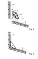
- the presentation of the Fig. 6 shows a kit for the construction of structures with a total of four mounting arrangements 10 according to the invention in an exploded view.
- the mounting assemblies 10 are inserted into a mounting bracket 56 which is to connect two C-shaped support rails 58, 62 at right angles to each other.
- the mounting bracket 56 is provided with passage openings 60, which are matched to the dimensions of the retaining disk 14 of the fastening arrangement 10. Especially can the securing portions 22 of the holding disc 14 extend into the passage opening 60, whereas the clamping portions 24 rest on an upper side of the mounting bracket 56. After inserting the fastening arrangement 10 into the passage opening 60, the retaining disk 14 is thus secured against rotation relative to the mounting bracket 56. The mounting bracket 56 is then placed on the top of one of the support rails 58, 62 and the screw 12 is pressed in the direction of the retaining rail 58, whereby, as explained, the sliding nut 16 is removed from the retaining disk 14.
- Fig. 7 shows the assembled state of the kit of Fig. 6 ,
- the mounting bracket now connects the two C-shaped support rails 58, 62 at right angles to each other.
Applications Claiming Priority (1)
| Application Number | Priority Date | Filing Date | Title |
|---|---|---|---|
| DE102014214853.7A DE102014214853A1 (de) | 2014-07-29 | 2014-07-29 | Befestigungsanordnung für C-förmige Halteschienen und Bausatz |
Publications (2)
| Publication Number | Publication Date |
|---|---|
| EP2980425A1 true EP2980425A1 (fr) | 2016-02-03 |
| EP2980425B1 EP2980425B1 (fr) | 2017-05-24 |
Family
ID=53510677
Family Applications (1)
| Application Number | Title | Priority Date | Filing Date |
|---|---|---|---|
| EP15174328.3A Active EP2980425B1 (fr) | 2014-07-29 | 2015-06-29 | Agencement de fixation pour rails de retenue en forme de c et kit |
Country Status (3)
| Country | Link |
|---|---|
| EP (1) | EP2980425B1 (fr) |
| DE (1) | DE102014214853A1 (fr) |
| ES (1) | ES2637810T3 (fr) |
Cited By (3)
| Publication number | Priority date | Publication date | Assignee | Title |
|---|---|---|---|---|
| WO2017080634A1 (fr) * | 2015-11-12 | 2017-05-18 | Fischerwerke Gmbh & Co. Kg | Ensemble de liaison pour rails de montage |
| WO2020096447A1 (fr) * | 2018-11-05 | 2020-05-14 | J. Van Walraven Holding B.V. | Élément de fixation de canal ayant un corps support effilé |
| NL2021934B1 (en) * | 2018-11-05 | 2020-05-15 | Walraven Holding Bv J Van | Channel fastener having tapering support body |
Families Citing this family (1)
| Publication number | Priority date | Publication date | Assignee | Title |
|---|---|---|---|---|
| DE102022203736A1 (de) | 2022-04-13 | 2023-10-19 | Adolf Würth GmbH & Co. KG | Befestigungsvorrichtung, Anordnung mit einer Befestigungsvorrichtung und Verfahren zum Herstellen einer Befestigungsvorrichtung |
Citations (5)
| Publication number | Priority date | Publication date | Assignee | Title |
|---|---|---|---|---|
| US4460299A (en) * | 1981-12-14 | 1984-07-17 | B-Line Systems, Inc. | Fastener |
| DE19912474C2 (de) | 1999-03-19 | 2001-05-10 | Wolfgang Pfitzmann | Befestigungsanordnung für die Anbringung eines Bauteils an einer C-förmigen Halteschiene |
| EP1201941A2 (fr) | 2000-10-23 | 2002-05-02 | HILTI Aktiengesellschaft | Dispositif d'attachement pour rail |
| WO2007008060A1 (fr) * | 2005-07-12 | 2007-01-18 | J. Van Walraven Holding B. V. | Ensemble de fixation |
| US20090087282A1 (en) * | 2007-10-02 | 2009-04-02 | Van Walraven Jan | Securing assembly |
Family Cites Families (1)
| Publication number | Priority date | Publication date | Assignee | Title |
|---|---|---|---|---|
| DE4243185A1 (de) * | 1992-12-19 | 1994-06-23 | Hilti Ag | Befestigungsvorrichtung |
-
2014
- 2014-07-29 DE DE102014214853.7A patent/DE102014214853A1/de not_active Withdrawn
-
2015
- 2015-06-29 EP EP15174328.3A patent/EP2980425B1/fr active Active
- 2015-06-29 ES ES15174328.3T patent/ES2637810T3/es active Active
Patent Citations (5)
| Publication number | Priority date | Publication date | Assignee | Title |
|---|---|---|---|---|
| US4460299A (en) * | 1981-12-14 | 1984-07-17 | B-Line Systems, Inc. | Fastener |
| DE19912474C2 (de) | 1999-03-19 | 2001-05-10 | Wolfgang Pfitzmann | Befestigungsanordnung für die Anbringung eines Bauteils an einer C-förmigen Halteschiene |
| EP1201941A2 (fr) | 2000-10-23 | 2002-05-02 | HILTI Aktiengesellschaft | Dispositif d'attachement pour rail |
| WO2007008060A1 (fr) * | 2005-07-12 | 2007-01-18 | J. Van Walraven Holding B. V. | Ensemble de fixation |
| US20090087282A1 (en) * | 2007-10-02 | 2009-04-02 | Van Walraven Jan | Securing assembly |
Cited By (8)
| Publication number | Priority date | Publication date | Assignee | Title |
|---|---|---|---|---|
| WO2017080634A1 (fr) * | 2015-11-12 | 2017-05-18 | Fischerwerke Gmbh & Co. Kg | Ensemble de liaison pour rails de montage |
| CN108350916A (zh) * | 2015-11-12 | 2018-07-31 | 费希尔厂有限责任两合公司 | 用于装配轨的连接组件 |
| CN108350916B (zh) * | 2015-11-12 | 2020-06-19 | 费希尔厂有限责任两合公司 | 用于装配轨的连接组件 |
| WO2020096447A1 (fr) * | 2018-11-05 | 2020-05-14 | J. Van Walraven Holding B.V. | Élément de fixation de canal ayant un corps support effilé |
| NL2021934B1 (en) * | 2018-11-05 | 2020-05-15 | Walraven Holding Bv J Van | Channel fastener having tapering support body |
| CN112955670A (zh) * | 2018-11-05 | 2021-06-11 | J·范瓦尔拉芬私人控股有限公司 | 具有渐缩的支撑主体的槽形件紧固件 |
| CN112955670B (zh) * | 2018-11-05 | 2023-02-24 | J·范瓦尔拉芬私人控股有限公司 | 具有渐缩的支撑主体的槽形件紧固件 |
| US11781585B2 (en) | 2018-11-05 | 2023-10-10 | J. Van Walraven Holding B.V. | Channel fastener having tapering support body |
Also Published As
| Publication number | Publication date |
|---|---|
| ES2637810T3 (es) | 2017-10-17 |
| EP2980425B1 (fr) | 2017-05-24 |
| DE102014214853A1 (de) | 2016-02-04 |
Similar Documents
| Publication | Publication Date | Title |
|---|---|---|
| EP2016293B1 (fr) | Verrou tournant | |
| DE102015118314A1 (de) | Verfahren zum Befestigen eines Befestigungselements an einer Montageschiene sowie Befestigungselement | |
| EP3209888B1 (fr) | Dispositif de fixation rapide, procédé d'assemblage de deux éléments au moyen du dispositif de fixation rapide, et procédé de fabrication afférent | |
| DE102017122236A1 (de) | Befestigungssystem zur Befestigung eines Bauteils an einem Trägerbauteil | |
| EP1626185A1 (fr) | Unité de réglage à ajuster la distance entre deux unités de construction | |
| DE102012102906A1 (de) | Befestigungsanordnung mit Toleranzausgleich sowie Verfahren zur Vormontage und Montage | |
| DE102014103535A1 (de) | Vorrichtung zur Befestigung eines Bauteils an einem Trägerbauteil | |
| EP2525022A2 (fr) | Cylindre de serrure modulaire | |
| EP2980425B1 (fr) | Agencement de fixation pour rails de retenue en forme de c et kit | |
| DE102013113735A1 (de) | Befestiger, Befestigungssystem und Verfahren zur Montage eines Befestigers an einer Montageschiene | |
| EP2000681B1 (fr) | Manchon support | |
| EP3122981B1 (fr) | Dispositif d'étanchéité et moyen pour fixation | |
| DE202007019077U1 (de) | Halteeinrichtung sowie Halteelement hierfür | |
| DE202005010186U1 (de) | Halteeinrichtung sowie Halteelement hierfür | |
| EP2816243B1 (fr) | Élément de fixation | |
| DE102012107571A1 (de) | Befestigungssystem zur Befestigung eines Verkleidungsteils | |
| EP3133305B1 (fr) | Écrou cage | |
| DE102012022239A1 (de) | Bauteil zur Befestigung an einem Trägerbauteil eines Automobils | |
| DE102013208494A1 (de) | Vorrichtung zur werkzeuglosen Verbindung zweier Bauteile | |
| EP2195480A1 (fr) | Lave-linge | |
| DE102016209395A1 (de) | Befestigungselement für den Toleranzausgleich | |
| DE19853951A1 (de) | Abdeck-Rosette | |
| EP3032113A1 (fr) | Procede de fixation d'un element de fixation sur un rail de montage et element de fixation | |
| DE102010052189B4 (de) | Vorrichtung zum Halten und Abdichten eines Rohres | |
| DE102018102488A1 (de) | Anordnung zur Positionierung eines Flachteils an einem Schaltschrankrahmengestell sowie ein entsprechendes Verfahren |
Legal Events
| Date | Code | Title | Description |
|---|---|---|---|
| PUAI | Public reference made under article 153(3) epc to a published international application that has entered the european phase |
Free format text: ORIGINAL CODE: 0009012 |
|
| AK | Designated contracting states |
Kind code of ref document: A1 Designated state(s): AL AT BE BG CH CY CZ DE DK EE ES FI FR GB GR HR HU IE IS IT LI LT LU LV MC MK MT NL NO PL PT RO RS SE SI SK SM TR |
|
| AX | Request for extension of the european patent |
Extension state: BA ME |
|
| 17P | Request for examination filed |
Effective date: 20160728 |
|
| RBV | Designated contracting states (corrected) |
Designated state(s): AL AT BE BG CH CY CZ DE DK EE ES FI FR GB GR HR HU IE IS IT LI LT LU LV MC MK MT NL NO PL PT RO RS SE SI SK SM TR |
|
| GRAP | Despatch of communication of intention to grant a patent |
Free format text: ORIGINAL CODE: EPIDOSNIGR1 |
|
| RAP1 | Party data changed (applicant data changed or rights of an application transferred) |
Owner name: ADOLF WUERTH GMBH & CO. KG Owner name: PROFILANKER GMBH |
|
| INTG | Intention to grant announced |
Effective date: 20161222 |
|
| RAP1 | Party data changed (applicant data changed or rights of an application transferred) |
Owner name: PROFILANKER GMBH Owner name: WUERTH INTERNATIONAL AG |
|
| RAP1 | Party data changed (applicant data changed or rights of an application transferred) |
Owner name: WUERTH INTERNATIONAL AG Owner name: PROFILANKER GMBH Owner name: ADOLF WUERTH GMBH & CO. KG |
|
| GRAS | Grant fee paid |
Free format text: ORIGINAL CODE: EPIDOSNIGR3 |
|
| GRAA | (expected) grant |
Free format text: ORIGINAL CODE: 0009210 |
|
| AK | Designated contracting states |
Kind code of ref document: B1 Designated state(s): AL AT BE BG CH CY CZ DE DK EE ES FI FR GB GR HR HU IE IS IT LI LT LU LV MC MK MT NL NO PL PT RO RS SE SI SK SM TR |
|
| REG | Reference to a national code |
Ref country code: GB Ref legal event code: FG4D Free format text: NOT ENGLISH |
|
| REG | Reference to a national code |
Ref country code: CH Ref legal event code: EP |
|
| REG | Reference to a national code |
Ref country code: IE Ref legal event code: FG4D Free format text: LANGUAGE OF EP DOCUMENT: GERMAN |
|
| REG | Reference to a national code |
Ref country code: AT Ref legal event code: REF Ref document number: 896167 Country of ref document: AT Kind code of ref document: T Effective date: 20170615 |
|
| REG | Reference to a national code |
Ref country code: FR Ref legal event code: PLFP Year of fee payment: 3 |
|
| REG | Reference to a national code |
Ref country code: DE Ref legal event code: R096 Ref document number: 502015001107 Country of ref document: DE |
|
| REG | Reference to a national code |
Ref country code: NL Ref legal event code: FP |
|
| REG | Reference to a national code |
Ref country code: LT Ref legal event code: MG4D |
|
| REG | Reference to a national code |
Ref country code: ES Ref legal event code: FG2A Ref document number: 2637810 Country of ref document: ES Kind code of ref document: T3 Effective date: 20171017 |
|
| PG25 | Lapsed in a contracting state [announced via postgrant information from national office to epo] |
Ref country code: GR Free format text: LAPSE BECAUSE OF FAILURE TO SUBMIT A TRANSLATION OF THE DESCRIPTION OR TO PAY THE FEE WITHIN THE PRESCRIBED TIME-LIMIT Effective date: 20170825 Ref country code: HR Free format text: LAPSE BECAUSE OF FAILURE TO SUBMIT A TRANSLATION OF THE DESCRIPTION OR TO PAY THE FEE WITHIN THE PRESCRIBED TIME-LIMIT Effective date: 20170524 Ref country code: LT Free format text: LAPSE BECAUSE OF FAILURE TO SUBMIT A TRANSLATION OF THE DESCRIPTION OR TO PAY THE FEE WITHIN THE PRESCRIBED TIME-LIMIT Effective date: 20170524 Ref country code: NO Free format text: LAPSE BECAUSE OF FAILURE TO SUBMIT A TRANSLATION OF THE DESCRIPTION OR TO PAY THE FEE WITHIN THE PRESCRIBED TIME-LIMIT Effective date: 20170824 |
|
| PG25 | Lapsed in a contracting state [announced via postgrant information from national office to epo] |
Ref country code: RS Free format text: LAPSE BECAUSE OF FAILURE TO SUBMIT A TRANSLATION OF THE DESCRIPTION OR TO PAY THE FEE WITHIN THE PRESCRIBED TIME-LIMIT Effective date: 20170524 Ref country code: LV Free format text: LAPSE BECAUSE OF FAILURE TO SUBMIT A TRANSLATION OF THE DESCRIPTION OR TO PAY THE FEE WITHIN THE PRESCRIBED TIME-LIMIT Effective date: 20170524 Ref country code: IS Free format text: LAPSE BECAUSE OF FAILURE TO SUBMIT A TRANSLATION OF THE DESCRIPTION OR TO PAY THE FEE WITHIN THE PRESCRIBED TIME-LIMIT Effective date: 20170924 Ref country code: SE Free format text: LAPSE BECAUSE OF FAILURE TO SUBMIT A TRANSLATION OF THE DESCRIPTION OR TO PAY THE FEE WITHIN THE PRESCRIBED TIME-LIMIT Effective date: 20170524 Ref country code: BG Free format text: LAPSE BECAUSE OF FAILURE TO SUBMIT A TRANSLATION OF THE DESCRIPTION OR TO PAY THE FEE WITHIN THE PRESCRIBED TIME-LIMIT Effective date: 20170824 |
|
| PG25 | Lapsed in a contracting state [announced via postgrant information from national office to epo] |
Ref country code: RO Free format text: LAPSE BECAUSE OF FAILURE TO SUBMIT A TRANSLATION OF THE DESCRIPTION OR TO PAY THE FEE WITHIN THE PRESCRIBED TIME-LIMIT Effective date: 20170524 Ref country code: DK Free format text: LAPSE BECAUSE OF FAILURE TO SUBMIT A TRANSLATION OF THE DESCRIPTION OR TO PAY THE FEE WITHIN THE PRESCRIBED TIME-LIMIT Effective date: 20170524 Ref country code: EE Free format text: LAPSE BECAUSE OF FAILURE TO SUBMIT A TRANSLATION OF THE DESCRIPTION OR TO PAY THE FEE WITHIN THE PRESCRIBED TIME-LIMIT Effective date: 20170524 Ref country code: SK Free format text: LAPSE BECAUSE OF FAILURE TO SUBMIT A TRANSLATION OF THE DESCRIPTION OR TO PAY THE FEE WITHIN THE PRESCRIBED TIME-LIMIT Effective date: 20170524 Ref country code: CZ Free format text: LAPSE BECAUSE OF FAILURE TO SUBMIT A TRANSLATION OF THE DESCRIPTION OR TO PAY THE FEE WITHIN THE PRESCRIBED TIME-LIMIT Effective date: 20170524 |
|
| REG | Reference to a national code |
Ref country code: DE Ref legal event code: R097 Ref document number: 502015001107 Country of ref document: DE |
|
| PG25 | Lapsed in a contracting state [announced via postgrant information from national office to epo] |
Ref country code: PL Free format text: LAPSE BECAUSE OF FAILURE TO SUBMIT A TRANSLATION OF THE DESCRIPTION OR TO PAY THE FEE WITHIN THE PRESCRIBED TIME-LIMIT Effective date: 20170524 Ref country code: SM Free format text: LAPSE BECAUSE OF FAILURE TO SUBMIT A TRANSLATION OF THE DESCRIPTION OR TO PAY THE FEE WITHIN THE PRESCRIBED TIME-LIMIT Effective date: 20170524 |
|
| PLBE | No opposition filed within time limit |
Free format text: ORIGINAL CODE: 0009261 |
|
| STAA | Information on the status of an ep patent application or granted ep patent |
Free format text: STATUS: NO OPPOSITION FILED WITHIN TIME LIMIT |
|
| REG | Reference to a national code |
Ref country code: IE Ref legal event code: MM4A |
|
| PG25 | Lapsed in a contracting state [announced via postgrant information from national office to epo] |
Ref country code: LU Free format text: LAPSE BECAUSE OF NON-PAYMENT OF DUE FEES Effective date: 20170629 Ref country code: IE Free format text: LAPSE BECAUSE OF NON-PAYMENT OF DUE FEES Effective date: 20170629 |
|
| 26N | No opposition filed |
Effective date: 20180227 |
|
| PG25 | Lapsed in a contracting state [announced via postgrant information from national office to epo] |
Ref country code: SI Free format text: LAPSE BECAUSE OF FAILURE TO SUBMIT A TRANSLATION OF THE DESCRIPTION OR TO PAY THE FEE WITHIN THE PRESCRIBED TIME-LIMIT Effective date: 20170524 |
|
| REG | Reference to a national code |
Ref country code: FR Ref legal event code: PLFP Year of fee payment: 4 |
|
| PGFP | Annual fee paid to national office [announced via postgrant information from national office to epo] |
Ref country code: NL Payment date: 20180620 Year of fee payment: 4 |
|
| PGFP | Annual fee paid to national office [announced via postgrant information from national office to epo] |
Ref country code: BE Payment date: 20180620 Year of fee payment: 4 |
|
| PG25 | Lapsed in a contracting state [announced via postgrant information from national office to epo] |
Ref country code: MT Free format text: LAPSE BECAUSE OF FAILURE TO SUBMIT A TRANSLATION OF THE DESCRIPTION OR TO PAY THE FEE WITHIN THE PRESCRIBED TIME-LIMIT Effective date: 20170524 |
|
| REG | Reference to a national code |
Ref country code: CH Ref legal event code: PL |
|
| PG25 | Lapsed in a contracting state [announced via postgrant information from national office to epo] |
Ref country code: CH Free format text: LAPSE BECAUSE OF NON-PAYMENT OF DUE FEES Effective date: 20180630 Ref country code: LI Free format text: LAPSE BECAUSE OF NON-PAYMENT OF DUE FEES Effective date: 20180630 |
|
| PG25 | Lapsed in a contracting state [announced via postgrant information from national office to epo] |
Ref country code: MC Free format text: LAPSE BECAUSE OF FAILURE TO SUBMIT A TRANSLATION OF THE DESCRIPTION OR TO PAY THE FEE WITHIN THE PRESCRIBED TIME-LIMIT Effective date: 20170524 Ref country code: HU Free format text: LAPSE BECAUSE OF FAILURE TO SUBMIT A TRANSLATION OF THE DESCRIPTION OR TO PAY THE FEE WITHIN THE PRESCRIBED TIME-LIMIT; INVALID AB INITIO Effective date: 20150629 |
|
| PG25 | Lapsed in a contracting state [announced via postgrant information from national office to epo] |
Ref country code: CY Free format text: LAPSE BECAUSE OF FAILURE TO SUBMIT A TRANSLATION OF THE DESCRIPTION OR TO PAY THE FEE WITHIN THE PRESCRIBED TIME-LIMIT Effective date: 20170524 |
|
| PG25 | Lapsed in a contracting state [announced via postgrant information from national office to epo] |
Ref country code: MK Free format text: LAPSE BECAUSE OF FAILURE TO SUBMIT A TRANSLATION OF THE DESCRIPTION OR TO PAY THE FEE WITHIN THE PRESCRIBED TIME-LIMIT Effective date: 20170524 |
|
| REG | Reference to a national code |
Ref country code: NL Ref legal event code: MM Effective date: 20190701 |
|
| GBPC | Gb: european patent ceased through non-payment of renewal fee |
Effective date: 20190629 |
|
| REG | Reference to a national code |
Ref country code: BE Ref legal event code: MM Effective date: 20190630 |
|
| PG25 | Lapsed in a contracting state [announced via postgrant information from national office to epo] |
Ref country code: TR Free format text: LAPSE BECAUSE OF FAILURE TO SUBMIT A TRANSLATION OF THE DESCRIPTION OR TO PAY THE FEE WITHIN THE PRESCRIBED TIME-LIMIT Effective date: 20170524 |
|
| PG25 | Lapsed in a contracting state [announced via postgrant information from national office to epo] |
Ref country code: NL Free format text: LAPSE BECAUSE OF NON-PAYMENT OF DUE FEES Effective date: 20190701 Ref country code: GB Free format text: LAPSE BECAUSE OF NON-PAYMENT OF DUE FEES Effective date: 20190629 |
|
| PG25 | Lapsed in a contracting state [announced via postgrant information from national office to epo] |
Ref country code: PT Free format text: LAPSE BECAUSE OF FAILURE TO SUBMIT A TRANSLATION OF THE DESCRIPTION OR TO PAY THE FEE WITHIN THE PRESCRIBED TIME-LIMIT Effective date: 20170524 Ref country code: BE Free format text: LAPSE BECAUSE OF NON-PAYMENT OF DUE FEES Effective date: 20190630 |
|
| PG25 | Lapsed in a contracting state [announced via postgrant information from national office to epo] |
Ref country code: AL Free format text: LAPSE BECAUSE OF FAILURE TO SUBMIT A TRANSLATION OF THE DESCRIPTION OR TO PAY THE FEE WITHIN THE PRESCRIBED TIME-LIMIT Effective date: 20170524 |
|
| P01 | Opt-out of the competence of the unified patent court (upc) registered |
Effective date: 20230609 |
|
| PGFP | Annual fee paid to national office [announced via postgrant information from national office to epo] |
Ref country code: FR Payment date: 20230628 Year of fee payment: 9 Ref country code: DE Payment date: 20230620 Year of fee payment: 9 |
|
| PGFP | Annual fee paid to national office [announced via postgrant information from national office to epo] |
Ref country code: FI Payment date: 20230621 Year of fee payment: 9 Ref country code: AT Payment date: 20230621 Year of fee payment: 9 |
|
| PGFP | Annual fee paid to national office [announced via postgrant information from national office to epo] |
Ref country code: IT Payment date: 20230623 Year of fee payment: 9 Ref country code: ES Payment date: 20230829 Year of fee payment: 9 |