EP2979769B1 - Thick steel plate manufacturing method and manufacturing device - Google Patents
Thick steel plate manufacturing method and manufacturing device Download PDFInfo
- Publication number
- EP2979769B1 EP2979769B1 EP14773154.1A EP14773154A EP2979769B1 EP 2979769 B1 EP2979769 B1 EP 2979769B1 EP 14773154 A EP14773154 A EP 14773154A EP 2979769 B1 EP2979769 B1 EP 2979769B1
- Authority
- EP
- European Patent Office
- Prior art keywords
- steel plate
- cooling
- water
- descaling
- temperature
- Prior art date
- Legal status (The legal status is an assumption and is not a legal conclusion. Google has not performed a legal analysis and makes no representation as to the accuracy of the status listed.)
- Active
Links
- 229910000831 Steel Inorganic materials 0.000 title claims description 217
- 239000010959 steel Substances 0.000 title claims description 217
- 238000004519 manufacturing process Methods 0.000 title claims description 28
- 238000001816 cooling Methods 0.000 claims description 153
- XLYOFNOQVPJJNP-UHFFFAOYSA-N water Substances O XLYOFNOQVPJJNP-UHFFFAOYSA-N 0.000 claims description 107
- 239000000498 cooling water Substances 0.000 claims description 94
- 230000009466 transformation Effects 0.000 claims description 21
- XEEYBQQBJWHFJM-UHFFFAOYSA-N Iron Chemical compound [Fe] XEEYBQQBJWHFJM-UHFFFAOYSA-N 0.000 claims description 20
- 238000000034 method Methods 0.000 claims description 20
- 238000012937 correction Methods 0.000 claims description 18
- 229910052742 iron Inorganic materials 0.000 claims description 10
- 229910001566 austenite Inorganic materials 0.000 claims description 8
- 229910000859 α-Fe Inorganic materials 0.000 claims description 8
- 238000005098 hot rolling Methods 0.000 claims description 6
- 238000011144 upstream manufacturing Methods 0.000 claims description 5
- 238000005192 partition Methods 0.000 description 45
- 238000005096 rolling process Methods 0.000 description 23
- 238000010586 diagram Methods 0.000 description 15
- 230000000052 comparative effect Effects 0.000 description 12
- 238000009826 distribution Methods 0.000 description 7
- 238000010438 heat treatment Methods 0.000 description 7
- 239000003657 drainage water Substances 0.000 description 5
- 239000007921 spray Substances 0.000 description 5
- 230000000694 effects Effects 0.000 description 3
- 239000012530 fluid Substances 0.000 description 3
- 230000006378 damage Effects 0.000 description 2
- 230000007423 decrease Effects 0.000 description 2
- 238000012423 maintenance Methods 0.000 description 2
- 230000002093 peripheral effect Effects 0.000 description 2
- 238000012546 transfer Methods 0.000 description 2
- 230000001131 transforming effect Effects 0.000 description 2
- 230000006866 deterioration Effects 0.000 description 1
- 238000007599 discharging Methods 0.000 description 1
- 238000006073 displacement reaction Methods 0.000 description 1
- 238000005265 energy consumption Methods 0.000 description 1
- 238000003780 insertion Methods 0.000 description 1
- 230000037431 insertion Effects 0.000 description 1
- 239000007788 liquid Substances 0.000 description 1
- 238000005259 measurement Methods 0.000 description 1
- 238000010926 purge Methods 0.000 description 1
- 238000003303 reheating Methods 0.000 description 1
Images


Classifications
-
- B—PERFORMING OPERATIONS; TRANSPORTING
- B21—MECHANICAL METAL-WORKING WITHOUT ESSENTIALLY REMOVING MATERIAL; PUNCHING METAL
- B21B—ROLLING OF METAL
- B21B45/00—Devices for surface or other treatment of work, specially combined with or arranged in, or specially adapted for use in connection with, metal-rolling mills
- B21B45/02—Devices for surface or other treatment of work, specially combined with or arranged in, or specially adapted for use in connection with, metal-rolling mills for lubricating, cooling, or cleaning
- B21B45/0203—Cooling
-
- B—PERFORMING OPERATIONS; TRANSPORTING
- B21—MECHANICAL METAL-WORKING WITHOUT ESSENTIALLY REMOVING MATERIAL; PUNCHING METAL
- B21B—ROLLING OF METAL
- B21B45/00—Devices for surface or other treatment of work, specially combined with or arranged in, or specially adapted for use in connection with, metal-rolling mills
- B21B45/04—Devices for surface or other treatment of work, specially combined with or arranged in, or specially adapted for use in connection with, metal-rolling mills for de-scaling, e.g. by brushing
- B21B45/08—Devices for surface or other treatment of work, specially combined with or arranged in, or specially adapted for use in connection with, metal-rolling mills for de-scaling, e.g. by brushing hydraulically
-
- B—PERFORMING OPERATIONS; TRANSPORTING
- B21—MECHANICAL METAL-WORKING WITHOUT ESSENTIALLY REMOVING MATERIAL; PUNCHING METAL
- B21B—ROLLING OF METAL
- B21B1/00—Metal-rolling methods or mills for making semi-finished products of solid or profiled cross-section; Sequence of operations in milling trains; Layout of rolling-mill plant, e.g. grouping of stands; Succession of passes or of sectional pass alternations
- B21B1/22—Metal-rolling methods or mills for making semi-finished products of solid or profiled cross-section; Sequence of operations in milling trains; Layout of rolling-mill plant, e.g. grouping of stands; Succession of passes or of sectional pass alternations for rolling plates, strips, bands or sheets of indefinite length
- B21B2001/225—Metal-rolling methods or mills for making semi-finished products of solid or profiled cross-section; Sequence of operations in milling trains; Layout of rolling-mill plant, e.g. grouping of stands; Succession of passes or of sectional pass alternations for rolling plates, strips, bands or sheets of indefinite length by hot-rolling
-
- B—PERFORMING OPERATIONS; TRANSPORTING
- B21—MECHANICAL METAL-WORKING WITHOUT ESSENTIALLY REMOVING MATERIAL; PUNCHING METAL
- B21B—ROLLING OF METAL
- B21B15/00—Arrangements for performing additional metal-working operations specially combined with or arranged in, or specially adapted for use in connection with, metal-rolling mills
- B21B2015/0071—Levelling the rolled product
-
- B—PERFORMING OPERATIONS; TRANSPORTING
- B21—MECHANICAL METAL-WORKING WITHOUT ESSENTIALLY REMOVING MATERIAL; PUNCHING METAL
- B21B—ROLLING OF METAL
- B21B45/00—Devices for surface or other treatment of work, specially combined with or arranged in, or specially adapted for use in connection with, metal-rolling mills
- B21B45/02—Devices for surface or other treatment of work, specially combined with or arranged in, or specially adapted for use in connection with, metal-rolling mills for lubricating, cooling, or cleaning
- B21B45/0203—Cooling
- B21B45/0209—Cooling devices, e.g. using gaseous coolants
- B21B2045/0212—Cooling devices, e.g. using gaseous coolants using gaseous coolants
-
- B—PERFORMING OPERATIONS; TRANSPORTING
- B21—MECHANICAL METAL-WORKING WITHOUT ESSENTIALLY REMOVING MATERIAL; PUNCHING METAL
- B21B—ROLLING OF METAL
- B21B2261/00—Product parameters
- B21B2261/20—Temperature
-
- B—PERFORMING OPERATIONS; TRANSPORTING
- B21—MECHANICAL METAL-WORKING WITHOUT ESSENTIALLY REMOVING MATERIAL; PUNCHING METAL
- B21B—ROLLING OF METAL
- B21B37/00—Control devices or methods specially adapted for metal-rolling mills or the work produced thereby
- B21B37/74—Temperature control, e.g. by cooling or heating the rolls or the product
-
- B—PERFORMING OPERATIONS; TRANSPORTING
- B21—MECHANICAL METAL-WORKING WITHOUT ESSENTIALLY REMOVING MATERIAL; PUNCHING METAL
- B21B—ROLLING OF METAL
- B21B45/00—Devices for surface or other treatment of work, specially combined with or arranged in, or specially adapted for use in connection with, metal-rolling mills
- B21B45/02—Devices for surface or other treatment of work, specially combined with or arranged in, or specially adapted for use in connection with, metal-rolling mills for lubricating, cooling, or cleaning
- B21B45/0203—Cooling
- B21B45/0209—Cooling devices, e.g. using gaseous coolants
- B21B45/0215—Cooling devices, e.g. using gaseous coolants using liquid coolants, e.g. for sections, for tubes
- B21B45/0218—Cooling devices, e.g. using gaseous coolants using liquid coolants, e.g. for sections, for tubes for strips, sheets, or plates
Definitions
- the present invention relates to a method and a facility for manufacturing a steel plate.
- a method and a facility in accordance with the preamble of claim 1 and claim 3 is e.g. known from document JP 2001300627 A .
- a steel plate (not shown) is reheated in a heating furnace 1
- the steel plate is descaled in a descaling apparatus 2.
- the steel plate is rolled by a rolling mill 3, is corrected by a shape correction apparatus 4, and is then subjected to controlled cooling by water cooling or air cooling in an accelerated cooling apparatus 5.
- the arrow in the figure indicates the direction of movement of the steel plate.
- cooling stop temperature distribution of the steel plate surface temperature when accelerated cooling is stopped (hereinafter referred to as "cooling stop temperature") in the width direction of the steel plate varies, for example, as shown in Fig. 3 .
- cooling stop temperature distribution of the steel plate surface temperature when accelerated cooling is stopped
- the cooling stop temperature when cooling the steel plate having a thickness of 25 mm from 800°C to a target temperature of 500°C is 460°C in the portions of 40 ⁇ m, and 500°C in the portions of 20 ⁇ m.
- the cooling stop temperature is lower than the target temperature by 40°C.
- Patent Literature 1 discloses a method for achieving uniformization of cooling stop temperature by controlling the scale thickness to uniformize the cooling rate.
- Patent Literature 1 using descaling apparatuses provided in front of and behind a rolling mill during rolling, when the cooling stop temperature of a tail end of the steel plate is lower than that of a front end thereof, the amount of jetted water in descaling on the tail end side is controlled so as to be larger than the amount of jetted water on the front end side and the scale removal rate and the residual thickness are controlled in the longitudinal direction of the steel plate. Thereby changing the heat transfer coefficient of the steel plate surface during the controlled cooling, the cooling stop temperature in the longitudinal direction of the steel plate is uniformized.
- An object of the present invention is to solve the above problems and to provide a method and a facility for manufacturing a steel plate, which can ensure a high-quality steel plate having less variation in quality.
- the present invention has been made to solve the conventional problems described above.
- the gist of the present invention is as follows:
- the present invention includes a temperature adjustment step of lowering the steel plate surface temperature below the Ar 3 transformation point to transform the steel plate surface between the shape correction step and the accelerated cooling step, and a descaling step of jetting high pressure water at an energy density of 0.05 J/mm 2 or more is jetted to the surfaces of the steel plate after the temperature adjustment step, thereby making it possible to uniformize the cooling rate and the cooling stop temperature. As a result, it is possible to manufacture a high-quality steel plate having less variation in quality.
- Fig. 4 is a schematic diagram showing a facility for manufacturing a steel plate that is an embodiment of the present invention.
- the arrow indicates a conveyance direction of the steel plate.
- a heating furnace 1, a descaling apparatus 2, a rolling mill 3, a shape correction apparatus 4, a temperature adjustment apparatus 6, a descaling apparatus 7, and an accelerated cooling apparatus 5 are arranged in this order from the upstream side in the conveyance direction of the steel plate.
- the steel plate (not shown) is reheated in the heating furnace 1, the steel plate is descaled for primary scale removal in the descaling apparatus 2.
- the steel plate is hot rolled by the rolling mill 3, and is corrected by the shape correction apparatus 4.
- the steel plate surface temperature is lowered in the temperature adjustment apparatus 6, descaling in which scale is completely removed is performed in the descaling apparatus 7.
- controlled cooling by water cooling or air cooling is performed in the accelerated cooling apparatus 5.
- the temperature adjustment apparatus 6 and the descaling apparatus 7 are disposed between the shape correction apparatus 4 and the accelerated cooling apparatus 5.
- the steel plate surface temperature is lowered below the Ar 3 transformation point to transform the steel plate surface.
- This embodiment is characterized in that thereafter descaling in which high pressure water having an energy density of 0.05 J/mm 2 or more is jetted to the steel plate is performed in the descaling apparatus 7.
- the temperature adjustment apparatus 6 is disposed between the shape correction apparatus 4 and the descaling apparatus 7. In the temperature adjustment step in the temperature adjustment apparatus 6, the steel plate surface temperature is lowered below the Ar 3 transformation point to transform the steel plate surface, thereby making it easier to remove scale in the subsequent descaling step.
- the steel plate surface temperature is lowered below the Ar 3 transformation point to transform the steel plate surface, transformation of base iron occurs.
- the transformation of base iron causes displacement at the interface between scale and base iron, and the adhesion of scale decreases. This is owing to the following mechanism.
- base iron is transformed from austenite to ferrite.
- base iron expands, therefore force is applied to the interface between scale and base iron, and cracks are generated at the interface.
- the adhesion of scale decreases. Therefore, by lowering the steel plate surface temperature below the Ar 3 transformation point to transform the steel plate surface, scale removal is facilitated during the descaling step in the descaling apparatus 7.
- the steel plate of which surface is transformed by lowering the steel plate surface temperature below the Ar 3 transformation point is subjected to descaling in which scale is removed in the descaling apparatus 7.
- high pressure water having an energy density of 0.05 J/mm 2 or more (in the present invention, high pressure water means a case where the jet pressure is 5 MPa or more) to the steel plate, scale can be completely removed.
- cooling control is made possible in the subsequent accelerated cooling step in the heating and cooling apparatus 5.
- the cooling rate and the cooling stop temperature can be precisely uniformized.
- High pressure water may be jetted over the entire length of the steel plate.
- the present inventors examined, using a certain type of steel, the relationship between the energy density of high pressure water and the scale removal rate (the proportion of the area where scale is removed to the area of the steel plate), in case of the presence or absence of transformation of the steel plate surface before the descaling step. As a result, findings shown in Fig. 5 were obtained. From Fig. 5 , it was found that when the energy density is high, the scale removal rate is high and that by transforming the steel plate surface, scale removal is made possible even when the energy density is low. Also, from Fig.
- the energy density of high pressure water is set to 0.05 J/mm 2 or more.
- the energy density of high pressure water is preferably 0.60 J/mm 2 or less.
- the descaling step it is preferable to jet high pressure water at a jet pressure of 10 MPa or more.
- the jet pressure By setting the jet pressure to 10 MPa or more, scale can be completely removed. Therefore, the uniformization of the cooling rate and the cooling stop temperature in the accelerated cooling step can be achieved.
- the present inventors examined the relationship between the temperature of the steel plate surface after the completion of rolling and the jet pressure of high pressure water required for the destruction of scale, and obtained the findings of Fig. 6 .
- the temperature of the steel plate surface after the completion of rolling is generally at the highest about 900°C. Therefore, in the present invention, in order to destroy scale, it is preferable that the jet pressure of high pressure water be set to 10 MPa or more.
- Q jet flow rate of descaling water [m 3 /s]
- d spray jet thickness [mm] of flat nozzle
- W spray jet width [mm] of flat nozzle
- fluid density ⁇ [kg/m 3 ] fluid velocity v [m/s] at the time of collision with steel plate
- water amount density ⁇ jet pressure ⁇ collision time may be used as a simple definition of the energy density E (J/mm 2 ) of cooling water jetted to the steel plate.
- water amount density (m 3 /m 2 ⁇ min) is a value calculated by "jet flow rate of cooling water ⁇ cooling water collision area”.
- Jet pressure (MPa) is defined as discharge pressure of cooling water.
- Collision time (s) is a value calculated by "the collision thickness of cooling water ⁇ the conveyance velocity of the steel plate.”
- the relationship between energy density of high pressure water and scale removal rate of the present invention calculated by this simple definition is also the same as Fig. 5 .
- the steel plate surface temperature is lowered below the Ar 3 transformation point by air cooling or water cooling.
- air cooling air cooling may be appropriately performed below the Ar 3 transformation point on a table roller for conveying the steel plate.
- cooling water is supplied to the upper and lower surfaces of the steel plate at a water amount density of 0.3 to 2.2 m 3 /m 2 ⁇ min. If the water amount density is less than 0.3 m 3 /m 2 ⁇ min, the steel plate surface temperature cannot be lowered below the Ar 3 transformation point, and the steel plate surface cannot be transformed. As a result, scale remains on the steel plate. Even if cooling control is performed in the subsequent accelerated cooling step, the cooling stop temperature varies and the quality is non-uniform. If the water amount density is more than 2.2 m 3 /m 2 ⁇ min, the amount of temperature drop ⁇ T in the temperature adjustment step to be described later exceeds 200°C, the cooling stop temperature varies and the quality is non-uniform.
- the steel plate surface in the temperature adjustment apparatus 6 When transforming the steel plate surface in the temperature adjustment apparatus 6, the steel plate surface is cooled in a state in which scale is adhering to the steel plate.
- the present inventors obtained findings that when the amount of temperature drop in the cooling in the temperature adjustment apparatus 6 is large, the adhesion state of scale affects the uniformization of the cooling stop temperature, and the variation in the cooling stop temperature (the difference between the target steel plate surface temperature after the accelerated cooling step and the actual steel plate surface temperature after the accelerated cooling) is large.
- the amount of temperature drop ⁇ T of the steel plate surface in the temperature adjustment apparatus 6 is defined, as shown in Fig. 7 , as the difference between the steel plate surface temperature at the start of cooling and the lowest reached temperature of the steel plate surface.
- the present inventors manufactured a steel plate, using a steel plate after the rolling in the rolling mill having a surface temperature of 800°C and a thickness of 25 mm, in the order of the temperature adjustment step, the descaling step and the accelerated cooling step.
- the energy density at the time of descaling was set to 0.2 J/mm 2 as a condition under which scale can be completely removed regardless whether the steel plate surface at the time of descaling is untransformed or transformed.
- the accelerated cooling step cooling was performed such that the steel plate surface temperature becomes 500°C.
- the relationship between the amount of temperature drop ⁇ T in the temperature adjustment step and the variation in the cooling stop temperature was found to be as shown in Fig. 8 . From Fig. 8 , in order to obtain uniform quality, it is preferable that the variation in the cooling stop temperature be 25°C or less, and the amount of temperature drop ⁇ T in the temperature adjustment step be 200°C or less.
- the accelerated cooling apparatus 5 of the present invention preferably includes an upper header 11 for supplying cooling water to the upper surface of the steel plate 10, cooling water jetting nozzles 13 that are suspended from the upper header 11 and that jet rod-like cooling water, and a partition wall 15 placed between the steel plate 10 and the upper header 11. Further, the partition wall 15 is preferably provided with many water supply ports 16 into which the lower ends of the cooling water jetting nozzles 13 are inserted, and many drainage ports 17 for draining the cooling water supplied to the upper surface of the steel plate 10 to above the partition wall 15.
- the upper surface cooling equipment includes an upper header 11 for supplying cooling water to the upper surface of the steel plate 10, cooling water jetting nozzles 13 that are suspended from the upper header 11, and a partition wall 15 that is placed horizontally between the upper header 11 and the steel plate 10 across the width direction of the steel plate and that has many through-holes (water supply ports 16 and drainage ports 17).
- the cooling water jetting nozzles 13 are circular tube nozzles 13 that jet rod-shaped cooling water, and the tips thereof are inserted into the through-holes (water supply ports 16) provided in the partition wall 15 and are placed so as to be above the lower end of the partition wall 15.
- the cooling water jetting nozzles 13 In order to prevent the cooling water jetting nozzles 13 from sucking the foreign matter in the bottom of the upper header 11 and clogging, the cooling water jetting nozzles 13 preferably penetrate into the upper header 11 so that the upper ends thereof protrude into the inside of the upper header 11.
- the rod-like cooling water in the present invention means cooling water that is jetted in a state of being pressurized to certain degree from nozzle jetting ports having a circular shape (including an elliptical shape and a polygonal shape), and cooling water of such continuous and linear water flows that the jet velocity of cooling water from the nozzle jetting ports is 6 m/s or more and preferably 8 m/s or more and the cross-section of water flows jetted from the nozzle jetting ports is kept substantially circular. That is, it differs from free fall flows from circular tube laminar nozzles and one that is jetted in a liquid droplet state, such as a spray.
- the reason why the tips of the cooling water jetting nozzles 13 are inserted into the through-holes and are placed so as to be above the lower end of the partition wall 15 is that if the steel plate whose front end is warped upward enters, the cooling water jetting nozzles 13 are prevented from being damaged by the partition wall 15. Therefore, since cooling can be performed in a state where the cooling water jetting nozzles 13 are in good condition over a long period of time, it is possible to prevent the occurrence of temperature unevenness of the steel plate without performing equipment maintenance or the like.
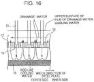
- the tips of the circular tube nozzles 13 are inserted into the through-holes, as shown in Fig. 16 , they does not interfere with the flow of drainage water 19 in the width direction indicated by the dotted arrow and flowing on the upper surface of the partition wall 15. Therefore, the cooling water jetted from the cooling water jetting nozzles 13 can reach the upper surface of the steel plate equally regardless of the position in the width direction, and cooling that is uniform in the width direction can be performed.
- the partition wall 15 As shown in Fig. 11 , many through-holes having a diameter of 10 mm are formed in the partition wall 15 in a grid at a pitch of 80 mm in the width direction of the steel plate and 80 mm in the conveyance direction.
- Cooling water jetting nozzles 13 having an outer diameter of 8 mm, an inner diameter of 3 mm, and a length of 140 mm are inserted into the water supply ports 16.
- the cooling water jetting nozzles 13 are arranged in a staggered manner, and through-holes through which the cooling water jetting nozzles 13 are not passed serve as drainage ports 17 for cooling water.
- the many through-holes provided in the partition wall 15 of the accelerated cooling apparatus of the present invention consist of approximately the same number of water supply ports 16 and drainage ports 17, which share roles and functions.
- the total cross-sectional area of the drainage ports 17 is sufficiently larger than the total cross-sectional area of the inner diameters of the circular tube nozzles 13 of the cooling water jetting nozzles 13, and about 11 times the total cross-sectional area of the inner diameters of the circular tube nozzle 13 is ensured.
- cooling water supplied to the upper surface of the steel plate fills the space between the steel plate surface and the partition wall 15, is guided to above the partition wall 15 through the drainage ports 17, and is rapidly discharged.
- Fig. 12 is a front view illustrating the flow of drainage cooling water on the partition wall and in the vicinity of an end in the width direction of the steel plate.
- the drainage direction of the drainage ports 17 is an upward direction which is opposite the cooling water jetting direction. After passing through the partition wall 15 to above the partition wall 15, drainage cooling water turns to the outer side in the width direction of the steel plate, flows through a drainage passage between the upper header 11 and the partition wall 15, and is drained.
- the drainage ports 17 are inclined in the width direction of steel plate and in an oblique direction toward the outer side in the width direction so that the drainage direction is directed to the outer side in the width direction of the steel plate. This is preferable because the flow of drainage water 19 on the partition wall 15 is smooth and the water discharge is facilitated.
- cooling water after colliding with the steel plate, is not apt to pass through the partition wall 15 to above the partition wall 15, and flows through the space between the steel plate 10 and the partition wall 15 toward an end in the width direction of the steel plate.
- the flow rate of the drainage cooling water between the steel plate 10 and the partition wall 15 increases toward the ends in the plate width direction. Therefore, the nearer the ends in the plate width direction, the more the force with which jetted cooling water 18 penetrates the film of stagnant water to reach the steel plate is inhibited.
- a width thereof is at most about 2 m, and therefore the effect is limited.
- the cooling of the ends in the width direction of the steel plate weakens, and the temperature distribution in the width direction of the steel plate in this case is a non-uniform.
- the water supply ports 16 and the drainage ports 17 are separately provided as shown in Fig. 15 , and share the roles of water supply and drainage, and therefore, drainage cooling water passes through the drainage ports 17 of the partition wall 15 and smoothly flows to above the partition wall 15. Therefore, the drainage water after cooling is removed rapidly from the upper surface of the steel plate, therefore cooling water supplied subsequently can penetrate the film of stagnant water easily, and a sufficient cooling capacity can be obtained.
- the temperature distribution in the width direction of the steel plate in this case is a uniform temperature distribution, and a temperature distribution that is uniform in the width direction can be obtained.
- the discharge of cooling water is performed rapidly. This can be achieved, for example, by forming holes larger than the outer diameter of the circular tube nozzles 13 in the partition wall 15, and making the number of drainage ports equal to or greater than the number of the water supply ports.
- the total cross-sectional area of the drainage ports 17 is less than 1.5 times the total cross-sectional area of the inner diameters of the circular tube nozzles 13 because the flow resistance of the drainage ports is increased, stagnant water is difficult to drain, and as a result, the amount of cooling water that can reach the steel plate surface through the film of stagnant water is greatly reduced, and the cooling capacity is reduced. More preferably, four times or more.
- the ratio of the total cross-sectional area of the drainage ports to the total cross-sectional area of the inner diameters of the circular tube nozzle 13 is preferably within the range of 1.5 to 20.
- the clearance between the outer peripheral surface of circular tube nozzle 13 inserted into water supply port 16 of the partition wall 15 and the inner surface of water supply port 16 is preferably 3 mm or less. If this clearance is large, owing to the accompanying flow of cooling water jetted from circular tube nozzle 13, the cooling drainage water discharged to the upper surface of the partition wall 15 is drawn into the clearance between water supply port 16 and the outer peripheral surface of circular tube nozzle 13, and is supplied onto the steel plate again, and therefore the cooling efficiency is deteriorated. To prevent this deterioration, it is more preferable to make the outer diameter of the circular tube nozzles 13 substantially the same as the size of the water supply ports 16. However, in consideration of working accuracy and mounting error, a clearance of up to 3 mm having a substantially low impact is acceptable. More preferably, 2 mm or less.
- the inner diameter and length of the circular tube nozzles 13, the jet velocity of cooling water, and the nozzle distance must also be optimized.
- the nozzle inner diameter is preferably 3 to 8 mm. If the nozzle inner diameter is less than 3 mm, the bundle of water jetted from nozzle becomes thin and the momentum becomes weak. On the other hand, if the nozzle diameter is more than 8 mm, the flow rate becomes low, and the force to penetrate the film of stagnant water becomes weak.
- the length of circular tube nozzle 13 is preferably 120 to 240 mm.
- the length of circular tube nozzle 13 herein means the length from the inlet port at the nozzle upper end penetrated into the header to some extent to the lower end of nozzle inserted into water supply port of the partition wall. If the circular tube nozzles 13 are shorter than 120 mm, the distance between the lower surface of the header and the upper surface of the partition wall is too short (for example, when the header thickness is 20 mm, the amount of protrusion of the nozzle upper end into the header is 20 mm, and the amount of insertion of the nozzle lower end into the partition wall is 10 mm, this distance is less than 70 mm). Therefore, the drainage space above the partition wall is small, and the drainage cooling water cannot be discharged smoothly. On the other hand, if the circular tube nozzles 13 are longer than 240 mm, pressure loss of the circular tube nozzles 13 is increased, and the force to penetrate the film of stagnant water becomes weak.
- the jet velocity of cooling water from the nozzles needs to be 6 m/s or more, and preferably 8 m/s or more. The reason is that, if the jet velocity is less than 6 m/s, the force with which cooling water penetrates the film of stagnant water is extremely weak.
- the jet velocity is preferably 8 m/s or more because a larger cooling capacity can be ensured.
- the distance from the lower end of cooling water jetting nozzle 13 for upper surface cooling to the surface of the steel plate 10 is preferably set to 30 to 120 mm. If this distance is less than 30 mm, the frequency at which the steel plate 10 collides with the partition wall 15 is extremely increased, and equipment maintenance is difficult. If this distance exceeds 120 mm, the force with which cooling water penetrates the film of stagnant water is extremely weak.
- draining rolls 20 In the cooling of the upper surface of the steel plate, draining rolls 20 is preferably placed in front of and behind the upper header 11 so that cooling water does not spread in the longitudinal direction of the steel plate. Owing to this, the cooling zone length becomes constant, and the temperature control is facilitated.
- the flow of cooling water in the steel plate conveyance direction is dammed by the draining rolls 20, and therefore drainage cooling water flows to the outer side in the width direction of the steel plate.
- cooling water tends to stagnate.
- the cooling water jetting nozzles of the row on the most upstream side in the steel plate conveyance direction be inclined at 15 to 60 degrees toward the upstream direction in the steel plate conveyance direction, and the cooling water jetting nozzles of the row on the most downstream side in the steel plate conveyance direction be inclined at 15 to 60 degrees toward the downstream direction in the steel plate conveyance direction.
- positions close to the draining rolls 20 can also be supplied with cooling water, cooling water does not stagnate in the vicinities of the draining rolls 20, and the cooling efficiency is improved.
- the distance between the lower surface of the upper header 11 and the upper surface of the partition wall 15 is provided such that the cross-sectional area of flow passage in the width direction of the steel plate in the space surrounded by the lower surface of the upper header and the upper surface of the partition wall is 1.5 or more times as large as the total cross-sectional area of the inner diameters of the cooling water jetting nozzles, for example, about 100 mm or more. If the cross-sectional area of flow passage in the width direction of the steel plate is less than 1.5 times as large as the total cross-sectional area of the inner diameters of the cooling water jetting nozzles, the drainage cooling water discharged through the drainage ports 17 provided in the partition wall to the upper surface of the partition wall 15 cannot be discharged smoothly in the width direction of the steel plate.
- the range of water amount density that is most effective is 1.5 m 3 /m 2 ⁇ min or more. If the water amount density is lower than this, the film of stagnant water is not so thick. There may be a case where even when a known technique in which rod-like cooling water is allowed to fall freely to cool a steel plate is applied, the temperature unevenness in the width direction is not so large. On the other hand, even when the water amount density is more than 4.0 m 3 /m 2 ⁇ min, the use of the technique of the present invention is effective, but there are practical problems such as an increase in equipment cost, and therefore the water amount density of 1.5 to 4.0 m 3 /m 2 ⁇ min is the most practical.
- the application of the cooling technique of the present invention is effective particularly for a case where draining rolls are disposed in front of and behind the cooling header.
- the cooling technique of the present invention can also be applied to a case where there is no draining rolls.
- the cooling technique of the present invention can also be applied to cooling equipment in which a header is relatively long in the longitudinal direction (in a case where the header is about 2 to 4 m long), and water spray for purging is jetted in front of and behind the header to prevent water leakage to the non-water cooling zones.
- the cooling apparatus on the lower surface side of the steel plate is not particularly limited.
- an example of lower cooling header 12 having the same circular tube nozzles 14 as those of the cooling apparatus on the upper surface side is not necessary.
- a partition wall 15 for discharging cooling water in the width direction of the steel plate as in the cooling of the upper surface side is not necessary.
- Known techniques that supply film-like cooling water, atomized spray cooling water, or the like may be used.
- the heating furnace 1 and the descaling apparatus 2 of the present invention are not particularly limited, and conventional apparatuses may be used.
- the descaling apparatus 2 need not have the same configuration as that of the descaling apparatus 7 of the present invention.
- the steel plate temperature is the temperature of surface thereof.
- a steel plate of the present invention was manufactured using the facility for manufacturing a steel plate shown in Fig. 4 .
- the temperature of the steel plate surface was adjusted in the temperature adjustment apparatus 6, and then descaling was performed in the descaling apparatus 7.
- the jet distance (the distance between jet nozzle of the descaling apparatus 7 and the surface of the steel plate) was set to 130 mm, the nozzle jet angle was set to 32°, and the nozzle angle of attack was set to 15°.
- cooling was performed to 500°C in the accelerated cooling apparatus 5.
- the temperature adjustment step and the descaling step after the temperature adjustment were performed under the conditions shown in Table 1.
- the cooling length of the temperature adjustment apparatus 6 was set to 1 m.
- the Ar 3 transformation point of the steel plate used was 780°C.
- the plate thickness was 25 mm, and the steel plate temperature was 830°C.
- the amount of temperature drop ⁇ T in the temperature adjustment step was measured only in the case where water cooling was used in the temperature adjustment step. This is because when temperature adjustment is performed by air cooling, the problem due to excessive temperature drop does not arise.
- Invention Example 4 after the completion of rolling, the steel plate surface temperature was lowered to 770°C in the temperature adjustment apparatus 6. Then, in the descaling apparatus 7, high pressure water was jetted over the entire length of the steel plate at an energy density of 0.13 J/mm 2 , and a jet pressure of 8 MPa, and then cooling is performed in the accelerated cooling apparatus to manufacture. Since the jet pressure was 8 MPa, and was of a value outside a range that is preferable in the present invention, it is thought that scale was not able be destroyed and slightly remained, and the temperature unevenness was 23°C. Although the jet pressure in Invention Example 4 was higher than in the case of Invention Example 3, which was within the preferable range of the present invention, the other conditions that were essential in the present invention were satisfied, and therefore the target, within 25°C, was achieved.
- Comparative Example 1 after the completion of rolling, the steel plate surface temperature was lowered to 770°C by air cooling in the temperature adjustment apparatus 6. Then, in the descaling apparatus 7, high pressure water was jetted over the entire length of the steel plate at an energy density of 0.04 J/mm 2 , and a jet pressure of 12 MPa, and then cooling is performed in the accelerated cooling apparatus 5 to manufacture. Since the energy density was 0.04 J/mm 2 , it is thought that scale remained in parts of the steel plate, and the temperature unevenness was 36°C. The surface of the steel plate of Comparative Example 1 that was cooled to room temperature was observed visually, and color tone unevenness was found on the surface. Therefore, the cause of the temperature unevenness is presumed to be caused by the fact that scale remained in parts of the steel plate.
- Comparative Example 2 after the completion of rolling, the steel plate surface temperature was not lowered in the temperature adjustment apparatus 6.
- the descaling apparatus 7 high pressure water was jetted to a steel plate having a steel plate surface temperature of 800°C over the entire length of the steel plate at an energy density of 0.08 J/mm 2 , and a jet pressure of 15 MPa, and then cooling is performed in the accelerated cooling apparatus 5 to manufacture.
- the energy density was within the range of the present invention.
- descaling was performed in a state where the surface of the steel plate is not transformed, it is thought that scale remained in parts of the steel plate, and the temperature unevenness was 40°C.
- the surface of the steel plate of Comparative Example 2 that was cooled to room temperature was observed visually, and color tone unevenness was found on the surface. Therefore, the cause of the temperature unevenness is presumed to be caused by the fact that scale remained in parts of the steel plate.
- Comparative Example 3 After the completion of rolling, cooling water was supplied to the upper and lower surfaces of a steel plate at a water amount density of 0.2 m 3 /m 2 ⁇ min in the temperature adjustment apparatus 6. Then, in the descaling apparatus 7, high pressure water was jetted over the entire length of the steel plate at an energy density of 0.08 J/mm 2 , and then cooling is performed in the accelerated cooling apparatus 5 to manufacture. Since the water amount density was as low as 0.2 m 3 /m 2 ⁇ min, the steel plate temperature was only lowered to 785°C, and descaling was performed in a state where the surface of the steel plate is not transformed. Therefore, it is thought that scale remained in parts of the steel plate, and the temperature unevenness was 41°C. The surface of the steel plate of Comparative Example 3 that was cooled to room temperature was observed visually, and color tone unevenness was found on the surface. Therefore, the cause of the temperature unevenness is presumed to be caused by the fact that scale remained in parts of the steel plate.
- Comparative Example 4 After the completion of rolling, cooling water was supplied to the upper and lower surfaces of a steel plate at a water amount density of 2.4 m 3 /m 2 ⁇ min in the temperature adjustment apparatus 6. After that, in the descaling apparatus 7, high pressure water was jetted over the entire length of the steel plate at an energy density of 0.08 J/mm 2 , and then cooling is performed in the accelerated cooling apparatus 5 to manufacture. Since the water amount density was as high as 2.4 m 3 /m 2 ⁇ min, ⁇ T at the time of cooling before descaling was 220°C, and the temperature unevenness was 27°C. The surface of the steel plate of Comparative Example 4 that was cooled to room temperature was observed visually, and color tone unevenness was found on the surface. Therefore, the cause of the temperature unevenness is presumed to be caused by the fact that scale remained in parts of the steel plate. Reference Signs List
Landscapes
- Engineering & Computer Science (AREA)
- Mechanical Engineering (AREA)
- Heat Treatments In General, Especially Conveying And Cooling (AREA)
- Metal Rolling (AREA)
- Heat Treatment Of Strip Materials And Filament Materials (AREA)
Applications Claiming Priority (2)
| Application Number | Priority Date | Filing Date | Title |
|---|---|---|---|
| JP2013065341A JP5720714B2 (ja) | 2013-03-27 | 2013-03-27 | 厚鋼板の製造方法および製造設備 |
| PCT/JP2014/001613 WO2014156085A1 (ja) | 2013-03-27 | 2014-03-20 | 厚鋼板の製造方法および製造設備 |
Publications (3)
| Publication Number | Publication Date |
|---|---|
| EP2979769A1 EP2979769A1 (en) | 2016-02-03 |
| EP2979769A4 EP2979769A4 (en) | 2016-03-02 |
| EP2979769B1 true EP2979769B1 (en) | 2018-08-15 |
Family
ID=51623099
Family Applications (1)
| Application Number | Title | Priority Date | Filing Date |
|---|---|---|---|
| EP14773154.1A Active EP2979769B1 (en) | 2013-03-27 | 2014-03-20 | Thick steel plate manufacturing method and manufacturing device |
Country Status (6)
| Country | Link |
|---|---|
| EP (1) | EP2979769B1 (ko) |
| JP (1) | JP5720714B2 (ko) |
| KR (1) | KR101691020B1 (ko) |
| CN (1) | CN105073293B (ko) |
| TW (1) | TWI569898B (ko) |
| WO (1) | WO2014156085A1 (ko) |
Cited By (1)
| Publication number | Priority date | Publication date | Assignee | Title |
|---|---|---|---|---|
| WO2021245355A1 (fr) * | 2020-06-04 | 2021-12-09 | Constellium Neuf-Brisach | Procede et equipement de refroidissement sur un laminoir reversible a chaud |
Families Citing this family (4)
| Publication number | Priority date | Publication date | Assignee | Title |
|---|---|---|---|---|
| JP6518948B2 (ja) * | 2016-03-31 | 2019-05-29 | Jfeスチール株式会社 | 鋼板の製造方法および製造設備 |
| KR101940872B1 (ko) * | 2016-12-21 | 2019-01-21 | 주식회사 포스코 | 유정관용 열연강판, 이를 이용한 강관 및 이들의 제조방법 |
| CN112007963B (zh) * | 2019-05-31 | 2022-08-12 | 宝山钢铁股份有限公司 | 带钢表面动态可调整除鳞压力控制方法和系统 |
| FR3112297B1 (fr) * | 2020-07-07 | 2024-02-09 | Constellium Neuf Brisach | Procédé et équipement de refroidissement sur un Laminoir réversible à chaud |
Family Cites Families (11)
| Publication number | Priority date | Publication date | Assignee | Title |
|---|---|---|---|---|
| JPH06330155A (ja) | 1993-05-26 | 1994-11-29 | Kawasaki Steel Corp | 厚鋼板の冷却方法 |
| US6068887A (en) * | 1997-11-26 | 2000-05-30 | Kawasaki Steel Corporation | Process for producing plated steel sheet |
| JP2001300627A (ja) * | 2000-04-18 | 2001-10-30 | Nippon Steel Corp | 厚鋼板冷却方法 |
| KR100496607B1 (ko) * | 2000-12-27 | 2005-06-22 | 주식회사 포스코 | 열연코일의 제조방법 및 그 장치 |
| JP2003220401A (ja) * | 2000-12-28 | 2003-08-05 | Jfe Steel Kk | 熱間圧延方法および熱間圧延ライン |
| KR101142620B1 (ko) * | 2007-03-27 | 2012-05-03 | 신닛뽄세이테쯔 카부시키카이샤 | 박리의 발생이 없어 표면 성상 및 버링성이 우수한 고강도 열연 강판 및 그 제조 방법 |
| KR101291832B1 (ko) * | 2008-07-16 | 2013-07-31 | 제이에프이 스틸 가부시키가이샤 | 열강판의 냉각 설비 및 냉각 방법 |
| CN101456034B (zh) * | 2009-01-06 | 2011-02-16 | 北京科技大学 | 一种生产x80级抗大变形管线钢中厚板的方法 |
| JP5614040B2 (ja) * | 2009-03-25 | 2014-10-29 | Jfeスチール株式会社 | 厚鋼板の製造設備及び製造方法 |
| AT507663B1 (de) * | 2009-04-09 | 2010-07-15 | Siemens Vai Metals Tech Gmbh | Verfahren und vorrichtung zum aufbereiten von warmwalzgut |
| JP5440203B2 (ja) * | 2010-01-22 | 2014-03-12 | Jfeスチール株式会社 | 高炭素熱延鋼板の製造方法 |
-
2013
- 2013-03-27 JP JP2013065341A patent/JP5720714B2/ja active Active
-
2014
- 2014-03-20 CN CN201480018326.5A patent/CN105073293B/zh active Active
- 2014-03-20 WO PCT/JP2014/001613 patent/WO2014156085A1/ja active Application Filing
- 2014-03-20 KR KR1020157025725A patent/KR101691020B1/ko active IP Right Grant
- 2014-03-20 EP EP14773154.1A patent/EP2979769B1/en active Active
- 2014-03-27 TW TW103111428A patent/TWI569898B/zh active
Non-Patent Citations (1)
| Title |
|---|
| None * |
Cited By (1)
| Publication number | Priority date | Publication date | Assignee | Title |
|---|---|---|---|---|
| WO2021245355A1 (fr) * | 2020-06-04 | 2021-12-09 | Constellium Neuf-Brisach | Procede et equipement de refroidissement sur un laminoir reversible a chaud |
Also Published As
| Publication number | Publication date |
|---|---|
| KR101691020B1 (ko) | 2016-12-29 |
| EP2979769A1 (en) | 2016-02-03 |
| EP2979769A4 (en) | 2016-03-02 |
| CN105073293B (zh) | 2017-03-15 |
| TW201446353A (zh) | 2014-12-16 |
| WO2014156085A1 (ja) | 2014-10-02 |
| JP2014188543A (ja) | 2014-10-06 |
| CN105073293A (zh) | 2015-11-18 |
| TWI569898B (zh) | 2017-02-11 |
| JP5720714B2 (ja) | 2015-05-20 |
| KR20150122186A (ko) | 2015-10-30 |
Similar Documents
| Publication | Publication Date | Title |
|---|---|---|
| JP4586791B2 (ja) | 熱延鋼帯の冷却方法 | |
| EP2412455B1 (en) | Method of manufacturing a steel plate | |
| EP2979769B1 (en) | Thick steel plate manufacturing method and manufacturing device | |
| KR100973692B1 (ko) | 강판의 열간압연 설비 및 열간압연 방법 | |
| EP3705587A1 (en) | Facility and method for producing thick steel sheet | |
| KR20090101369A (ko) | 열연 강대의 냉각 장치 및 방법 | |
| JP5515483B2 (ja) | 厚鋼板の冷却設備および冷却方法 | |
| EP3397781B1 (en) | Process and device for cooling a metal substrate | |
| EP2979770B1 (en) | Thick steel plate manufacturing device and manufacturing method | |
| KR20200085880A (ko) | 후강판의 냉각 장치 및 냉각 방법 그리고 후강판의 제조 설비 및 제조 방법 | |
| EP3195946B1 (en) | Thick steel plate manufacturing method | |
| EP3187275B1 (en) | Thick steel plate manufacturing method | |
| JP5387093B2 (ja) | 熱鋼板の冷却設備 | |
| JP5347781B2 (ja) | 熱鋼板の冷却設備および冷却方法 |
Legal Events
| Date | Code | Title | Description |
|---|---|---|---|
| PUAI | Public reference made under article 153(3) epc to a published international application that has entered the european phase |
Free format text: ORIGINAL CODE: 0009012 |
|
| 17P | Request for examination filed |
Effective date: 20150907 |
|
| AK | Designated contracting states |
Kind code of ref document: A1 Designated state(s): AL AT BE BG CH CY CZ DE DK EE ES FI FR GB GR HR HU IE IS IT LI LT LU LV MC MK MT NL NO PL PT RO RS SE SI SK SM TR |
|
| AX | Request for extension of the european patent |
Extension state: BA ME |
|
| A4 | Supplementary search report drawn up and despatched |
Effective date: 20160203 |
|
| RIC1 | Information provided on ipc code assigned before grant |
Ipc: B21B 45/02 20060101ALI20160128BHEP Ipc: B21B 45/08 20060101AFI20160128BHEP |
|
| DAX | Request for extension of the european patent (deleted) | ||
| STAA | Information on the status of an ep patent application or granted ep patent |
Free format text: STATUS: EXAMINATION IS IN PROGRESS |
|
| 17Q | First examination report despatched |
Effective date: 20170321 |
|
| GRAP | Despatch of communication of intention to grant a patent |
Free format text: ORIGINAL CODE: EPIDOSNIGR1 |
|
| STAA | Information on the status of an ep patent application or granted ep patent |
Free format text: STATUS: GRANT OF PATENT IS INTENDED |
|
| INTG | Intention to grant announced |
Effective date: 20180306 |
|
| GRAS | Grant fee paid |
Free format text: ORIGINAL CODE: EPIDOSNIGR3 |
|
| GRAA | (expected) grant |
Free format text: ORIGINAL CODE: 0009210 |
|
| STAA | Information on the status of an ep patent application or granted ep patent |
Free format text: STATUS: THE PATENT HAS BEEN GRANTED |
|
| AK | Designated contracting states |
Kind code of ref document: B1 Designated state(s): AL AT BE BG CH CY CZ DE DK EE ES FI FR GB GR HR HU IE IS IT LI LT LU LV MC MK MT NL NO PL PT RO RS SE SI SK SM TR |
|
| REG | Reference to a national code |
Ref country code: CH Ref legal event code: EP Ref country code: GB Ref legal event code: FG4D Ref country code: AT Ref legal event code: REF Ref document number: 1029164 Country of ref document: AT Kind code of ref document: T Effective date: 20180815 |
|
| REG | Reference to a national code |
Ref country code: IE Ref legal event code: FG4D |
|
| REG | Reference to a national code |
Ref country code: DE Ref legal event code: R096 Ref document number: 602014030508 Country of ref document: DE |
|
| REG | Reference to a national code |
Ref country code: NL Ref legal event code: MP Effective date: 20180815 |
|
| REG | Reference to a national code |
Ref country code: LT Ref legal event code: MG4D |
|
| REG | Reference to a national code |
Ref country code: AT Ref legal event code: MK05 Ref document number: 1029164 Country of ref document: AT Kind code of ref document: T Effective date: 20180815 |
|
| PG25 | Lapsed in a contracting state [announced via postgrant information from national office to epo] |
Ref country code: AT Free format text: LAPSE BECAUSE OF FAILURE TO SUBMIT A TRANSLATION OF THE DESCRIPTION OR TO PAY THE FEE WITHIN THE PRESCRIBED TIME-LIMIT Effective date: 20180815 Ref country code: NL Free format text: LAPSE BECAUSE OF FAILURE TO SUBMIT A TRANSLATION OF THE DESCRIPTION OR TO PAY THE FEE WITHIN THE PRESCRIBED TIME-LIMIT Effective date: 20180815 Ref country code: RS Free format text: LAPSE BECAUSE OF FAILURE TO SUBMIT A TRANSLATION OF THE DESCRIPTION OR TO PAY THE FEE WITHIN THE PRESCRIBED TIME-LIMIT Effective date: 20180815 Ref country code: LT Free format text: LAPSE BECAUSE OF FAILURE TO SUBMIT A TRANSLATION OF THE DESCRIPTION OR TO PAY THE FEE WITHIN THE PRESCRIBED TIME-LIMIT Effective date: 20180815 Ref country code: GR Free format text: LAPSE BECAUSE OF FAILURE TO SUBMIT A TRANSLATION OF THE DESCRIPTION OR TO PAY THE FEE WITHIN THE PRESCRIBED TIME-LIMIT Effective date: 20181116 Ref country code: IS Free format text: LAPSE BECAUSE OF FAILURE TO SUBMIT A TRANSLATION OF THE DESCRIPTION OR TO PAY THE FEE WITHIN THE PRESCRIBED TIME-LIMIT Effective date: 20181215 Ref country code: NO Free format text: LAPSE BECAUSE OF FAILURE TO SUBMIT A TRANSLATION OF THE DESCRIPTION OR TO PAY THE FEE WITHIN THE PRESCRIBED TIME-LIMIT Effective date: 20181115 Ref country code: FI Free format text: LAPSE BECAUSE OF FAILURE TO SUBMIT A TRANSLATION OF THE DESCRIPTION OR TO PAY THE FEE WITHIN THE PRESCRIBED TIME-LIMIT Effective date: 20180815 Ref country code: SE Free format text: LAPSE BECAUSE OF FAILURE TO SUBMIT A TRANSLATION OF THE DESCRIPTION OR TO PAY THE FEE WITHIN THE PRESCRIBED TIME-LIMIT Effective date: 20180815 Ref country code: BG Free format text: LAPSE BECAUSE OF FAILURE TO SUBMIT A TRANSLATION OF THE DESCRIPTION OR TO PAY THE FEE WITHIN THE PRESCRIBED TIME-LIMIT Effective date: 20181115 |
|
| PG25 | Lapsed in a contracting state [announced via postgrant information from national office to epo] |
Ref country code: LV Free format text: LAPSE BECAUSE OF FAILURE TO SUBMIT A TRANSLATION OF THE DESCRIPTION OR TO PAY THE FEE WITHIN THE PRESCRIBED TIME-LIMIT Effective date: 20180815 Ref country code: AL Free format text: LAPSE BECAUSE OF FAILURE TO SUBMIT A TRANSLATION OF THE DESCRIPTION OR TO PAY THE FEE WITHIN THE PRESCRIBED TIME-LIMIT Effective date: 20180815 Ref country code: HR Free format text: LAPSE BECAUSE OF FAILURE TO SUBMIT A TRANSLATION OF THE DESCRIPTION OR TO PAY THE FEE WITHIN THE PRESCRIBED TIME-LIMIT Effective date: 20180815 |
|
| PG25 | Lapsed in a contracting state [announced via postgrant information from national office to epo] |
Ref country code: IT Free format text: LAPSE BECAUSE OF FAILURE TO SUBMIT A TRANSLATION OF THE DESCRIPTION OR TO PAY THE FEE WITHIN THE PRESCRIBED TIME-LIMIT Effective date: 20180815 Ref country code: EE Free format text: LAPSE BECAUSE OF FAILURE TO SUBMIT A TRANSLATION OF THE DESCRIPTION OR TO PAY THE FEE WITHIN THE PRESCRIBED TIME-LIMIT Effective date: 20180815 Ref country code: PL Free format text: LAPSE BECAUSE OF FAILURE TO SUBMIT A TRANSLATION OF THE DESCRIPTION OR TO PAY THE FEE WITHIN THE PRESCRIBED TIME-LIMIT Effective date: 20180815 Ref country code: ES Free format text: LAPSE BECAUSE OF FAILURE TO SUBMIT A TRANSLATION OF THE DESCRIPTION OR TO PAY THE FEE WITHIN THE PRESCRIBED TIME-LIMIT Effective date: 20180815 Ref country code: RO Free format text: LAPSE BECAUSE OF FAILURE TO SUBMIT A TRANSLATION OF THE DESCRIPTION OR TO PAY THE FEE WITHIN THE PRESCRIBED TIME-LIMIT Effective date: 20180815 Ref country code: CZ Free format text: LAPSE BECAUSE OF FAILURE TO SUBMIT A TRANSLATION OF THE DESCRIPTION OR TO PAY THE FEE WITHIN THE PRESCRIBED TIME-LIMIT Effective date: 20180815 |
|
| REG | Reference to a national code |
Ref country code: DE Ref legal event code: R097 Ref document number: 602014030508 Country of ref document: DE |
|
| PG25 | Lapsed in a contracting state [announced via postgrant information from national office to epo] |
Ref country code: SK Free format text: LAPSE BECAUSE OF FAILURE TO SUBMIT A TRANSLATION OF THE DESCRIPTION OR TO PAY THE FEE WITHIN THE PRESCRIBED TIME-LIMIT Effective date: 20180815 Ref country code: DK Free format text: LAPSE BECAUSE OF FAILURE TO SUBMIT A TRANSLATION OF THE DESCRIPTION OR TO PAY THE FEE WITHIN THE PRESCRIBED TIME-LIMIT Effective date: 20180815 Ref country code: SM Free format text: LAPSE BECAUSE OF FAILURE TO SUBMIT A TRANSLATION OF THE DESCRIPTION OR TO PAY THE FEE WITHIN THE PRESCRIBED TIME-LIMIT Effective date: 20180815 |
|
| PLBE | No opposition filed within time limit |
Free format text: ORIGINAL CODE: 0009261 |
|
| STAA | Information on the status of an ep patent application or granted ep patent |
Free format text: STATUS: NO OPPOSITION FILED WITHIN TIME LIMIT |
|
| 26N | No opposition filed |
Effective date: 20190516 |
|
| PG25 | Lapsed in a contracting state [announced via postgrant information from national office to epo] |
Ref country code: SI Free format text: LAPSE BECAUSE OF FAILURE TO SUBMIT A TRANSLATION OF THE DESCRIPTION OR TO PAY THE FEE WITHIN THE PRESCRIBED TIME-LIMIT Effective date: 20180815 |
|
| PG25 | Lapsed in a contracting state [announced via postgrant information from national office to epo] |
Ref country code: MC Free format text: LAPSE BECAUSE OF FAILURE TO SUBMIT A TRANSLATION OF THE DESCRIPTION OR TO PAY THE FEE WITHIN THE PRESCRIBED TIME-LIMIT Effective date: 20180815 |
|
| REG | Reference to a national code |
Ref country code: CH Ref legal event code: PL |
|
| GBPC | Gb: european patent ceased through non-payment of renewal fee |
Effective date: 20190320 |
|
| PG25 | Lapsed in a contracting state [announced via postgrant information from national office to epo] |
Ref country code: LU Free format text: LAPSE BECAUSE OF NON-PAYMENT OF DUE FEES Effective date: 20190320 |
|
| REG | Reference to a national code |
Ref country code: BE Ref legal event code: MM Effective date: 20190331 |
|
| PG25 | Lapsed in a contracting state [announced via postgrant information from national office to epo] |
Ref country code: LI Free format text: LAPSE BECAUSE OF NON-PAYMENT OF DUE FEES Effective date: 20190331 Ref country code: GB Free format text: LAPSE BECAUSE OF NON-PAYMENT OF DUE FEES Effective date: 20190320 Ref country code: IE Free format text: LAPSE BECAUSE OF NON-PAYMENT OF DUE FEES Effective date: 20190320 Ref country code: CH Free format text: LAPSE BECAUSE OF NON-PAYMENT OF DUE FEES Effective date: 20190331 |
|
| PG25 | Lapsed in a contracting state [announced via postgrant information from national office to epo] |
Ref country code: BE Free format text: LAPSE BECAUSE OF NON-PAYMENT OF DUE FEES Effective date: 20190331 Ref country code: FR Free format text: LAPSE BECAUSE OF NON-PAYMENT OF DUE FEES Effective date: 20190331 |
|
| PG25 | Lapsed in a contracting state [announced via postgrant information from national office to epo] |
Ref country code: TR Free format text: LAPSE BECAUSE OF FAILURE TO SUBMIT A TRANSLATION OF THE DESCRIPTION OR TO PAY THE FEE WITHIN THE PRESCRIBED TIME-LIMIT Effective date: 20180815 |
|
| PG25 | Lapsed in a contracting state [announced via postgrant information from national office to epo] |
Ref country code: PT Free format text: LAPSE BECAUSE OF FAILURE TO SUBMIT A TRANSLATION OF THE DESCRIPTION OR TO PAY THE FEE WITHIN THE PRESCRIBED TIME-LIMIT Effective date: 20181215 Ref country code: MT Free format text: LAPSE BECAUSE OF NON-PAYMENT OF DUE FEES Effective date: 20190320 |
|
| REG | Reference to a national code |
Ref country code: DE Ref legal event code: R082 Ref document number: 602014030508 Country of ref document: DE Representative=s name: HL KEMPNER PATENTANWAELTE, SOLICITORS (ENGLAND, DE Ref country code: DE Ref legal event code: R082 Ref document number: 602014030508 Country of ref document: DE Representative=s name: HL KEMPNER PATENTANWALT, RECHTSANWALT, SOLICIT, DE |
|
| PG25 | Lapsed in a contracting state [announced via postgrant information from national office to epo] |
Ref country code: CY Free format text: LAPSE BECAUSE OF FAILURE TO SUBMIT A TRANSLATION OF THE DESCRIPTION OR TO PAY THE FEE WITHIN THE PRESCRIBED TIME-LIMIT Effective date: 20180815 |
|
| PG25 | Lapsed in a contracting state [announced via postgrant information from national office to epo] |
Ref country code: HU Free format text: LAPSE BECAUSE OF FAILURE TO SUBMIT A TRANSLATION OF THE DESCRIPTION OR TO PAY THE FEE WITHIN THE PRESCRIBED TIME-LIMIT; INVALID AB INITIO Effective date: 20140320 |
|
| PG25 | Lapsed in a contracting state [announced via postgrant information from national office to epo] |
Ref country code: MK Free format text: LAPSE BECAUSE OF FAILURE TO SUBMIT A TRANSLATION OF THE DESCRIPTION OR TO PAY THE FEE WITHIN THE PRESCRIBED TIME-LIMIT Effective date: 20180815 |
|
| PGFP | Annual fee paid to national office [announced via postgrant information from national office to epo] |
Ref country code: DE Payment date: 20230131 Year of fee payment: 10 |