EP2979284B1 - Energy storage device - Google Patents
Energy storage device Download PDFInfo
- Publication number
- EP2979284B1 EP2979284B1 EP14774940.2A EP14774940A EP2979284B1 EP 2979284 B1 EP2979284 B1 EP 2979284B1 EP 14774940 A EP14774940 A EP 14774940A EP 2979284 B1 EP2979284 B1 EP 2979284B1
- Authority
- EP
- European Patent Office
- Prior art keywords
- viscosity
- dielectric
- dielectric material
- controllable
- capacitor according
- Prior art date
- Legal status (The legal status is an assumption and is not a legal conclusion. Google has not performed a legal analysis and makes no representation as to the accuracy of the status listed.)
- Active
Links
Images


Classifications
-
- H—ELECTRICITY
- H01—ELECTRIC ELEMENTS
- H01G—CAPACITORS; CAPACITORS, RECTIFIERS, DETECTORS, SWITCHING DEVICES, LIGHT-SENSITIVE OR TEMPERATURE-SENSITIVE DEVICES OF THE ELECTROLYTIC TYPE
- H01G9/00—Electrolytic capacitors, rectifiers, detectors, switching devices, light-sensitive or temperature-sensitive devices; Processes of their manufacture
- H01G9/004—Details
- H01G9/022—Electrolytes; Absorbents
- H01G9/025—Solid electrolytes
-
- H—ELECTRICITY
- H01—ELECTRIC ELEMENTS
- H01G—CAPACITORS; CAPACITORS, RECTIFIERS, DETECTORS, SWITCHING DEVICES, LIGHT-SENSITIVE OR TEMPERATURE-SENSITIVE DEVICES OF THE ELECTROLYTIC TYPE
- H01G11/00—Hybrid capacitors, i.e. capacitors having different positive and negative electrodes; Electric double-layer [EDL] capacitors; Processes for the manufacture thereof or of parts thereof
- H01G11/52—Separators
-
- H—ELECTRICITY
- H01—ELECTRIC ELEMENTS
- H01G—CAPACITORS; CAPACITORS, RECTIFIERS, DETECTORS, SWITCHING DEVICES, LIGHT-SENSITIVE OR TEMPERATURE-SENSITIVE DEVICES OF THE ELECTROLYTIC TYPE
- H01G11/00—Hybrid capacitors, i.e. capacitors having different positive and negative electrodes; Electric double-layer [EDL] capacitors; Processes for the manufacture thereof or of parts thereof
- H01G11/54—Electrolytes
- H01G11/56—Solid electrolytes, e.g. gels; Additives therein
-
- H—ELECTRICITY
- H01—ELECTRIC ELEMENTS
- H01G—CAPACITORS; CAPACITORS, RECTIFIERS, DETECTORS, SWITCHING DEVICES, LIGHT-SENSITIVE OR TEMPERATURE-SENSITIVE DEVICES OF THE ELECTROLYTIC TYPE
- H01G9/00—Electrolytic capacitors, rectifiers, detectors, switching devices, light-sensitive or temperature-sensitive devices; Processes of their manufacture
- H01G9/004—Details
- H01G9/02—Diaphragms; Separators
Definitions
- This invention relates generally to an energy storage device, and, more particularly, to an electro-active electrical component used to store energy electrostatically in an electric field.
- Double layer-type capacitors use an electrical double layer (explained below) to achieve a very small charge separation (d), which increases electric field ( E ) for a given voltage, increases capacitance (C) and consequently increases the energy stored (U) for the given voltage versus a conventional planar surface capacitor, as apparent in Eqs. 1 through 3 below.
- E V d
- E electric field
- V potential difference or voltage
- d separation of charged plates.
- EDLCs electric double layer capacitors
- pseudocapacitors which are a hybrid between double-layer capacitors and batteries, both the bulk and the surface of the material play key roles. They thus can store much more energy than conventional planar surface capacitors, but face many of the same reliability and scientific challenges as advanced batteries, including high cost due to expensive raw materials and complex processing.
- Pseudocapacitance imitates battery technology by storing energy in chemical reactions (oxidation and reduction) which take place at or very near the surface of the relevant electrodes. The surface nature of the reactions is the distinguishing characteristic from chemical battery technology.
- Patent document US 2005/186437 A1 discloses capacitor structures comprising a pair of parallel electrically conductive layers separated by a pair of dielectric layers and a central polymerizable layer.
- the invention is directed towards overcoming one or more of the fundamental problems with existing designs and solving one or more of the needs as set forth above.
- an energy storage device comprises a capacitor according to claim 1.
- a second nonconductive coating may be provided on the second conductive electrode, disposed between the second conductive electrode and the dielectric material.
- the nonconductive coatings are thin, having a thickness that is less than 10% of the overall thickness of the energy storage device.
- the nonconductive coatings may be comprised of a condensed and polymerized xylylene monomer, a parylene polymer, PuraleneTM polymer, a metal oxide, or some other insulator that can be deposited or otherwise formed in a thin film on the electrode(s).
- the nonconductive coatings constitute insulating layers that allow for much higher voltages to be employed than in traditional EDLCs. This extends the layers from just a few (two or three which alternate in charge) to many (possibly orders of magnitude more in number) which can reach far into the dielectric medium. The increase in working voltage, significantly increases the electric field present in the capacitor and energy stored in the capacitor.
- the dielectric material is a variable viscosity dielectric material.
- the viscosity may be increased or decreased in a controlled manner, such as in response to an applied external stimulus.
- the external stimulus may be a force, a pressure, a shear stress, a normal stress, heat, a heat sink, a coolant, a magnetic field, or an electric field.
- the external stimulus may comprise a mechanism from the group consisting of a controllable heat source, a heat sink, a coolant, a controllable cooling source, a controllable magnetic field generator, a controllable electric field generator, a controllable force generator, a controllable pressure generator, or a controllable shear stress generator.
- Viscosity of the dielectric can be made to gradually increase from electrode layer to electrode layer sequentially, or vice versa. With a viscosity increase, the discharge of the Helmholtz and Diffuse Helmholtz layers as thermal energy can be slowed and essentially halted with complete solidification. Electrical energy can thereby be stored for extended periods of time until ready for release. When ready for release, the viscosity may be reduced in a controlled manner such as by removing a viscosity-increasing stimulus or by applying a viscosity-decreasing stimulus. The reduction of viscosity facilitates discharge.
- the dielectric material may be comprised of a dielectric substance such as a conductive polymer, a nonconductive polymer, an inorganic metal oxide, a metal oxide mixture, a biopolymers or some other dielectric substance with a changeable viscosity.
- a dielectric substance such as a conductive polymer, a nonconductive polymer, an inorganic metal oxide, a metal oxide mixture, a biopolymers or some other dielectric substance with a changeable viscosity.
- an insulating layer directly allows for much higher voltages to be employed than in traditional EDLCs. This in turn increases the number of layers from just a few (two or three which alternate in charge) to many (possibly orders of magnitude more in number) which can reach far into the dielectric medium.
- a treatment as series capacitors demonstrates that, for a set amount of charge, adding more layers will actually decrease capacitance and increase voltage. This increase in working voltage (both directly and indirectly from the use of an insulating layer) along with the small degree of charge separation previously observed in EDLCs, significantly increases the electric field present in the capacitor as can be seen from Eq. 1 (above).
- Helmholtz proposed that the interface between a metallic electrode and an electrolyte solution behaves like a capacitor in that it is capable of storing an electric charge.
- the Helmholtz model is conceptually illustrated in FIG. 1 .
- Helmholtz's proposed model is that the electrode possesses a charge density arising from an excess negative or deficiency of positive charges at the electrode surface. In the model, the charge on the electrode is exactly balanced in solution by an equal but oppositely charged amount of ions.
- This charge originates from the arrangement of electrolyte ions at the interface and/or the reorientation of dipoles in solvent molecules. A potential difference occurs across the interface, forming an electric field gradient across a charge separation layer. Ions are electrostatically repelled or attracted towards the electrode surface and an excess of either anions or cations is created.
- the Gouy-Chapman model was introduced.
- Gouy employed statistical mechanics to develop his theory and suggested that the thermal motion of the medium prevents the formation of an organized layer.
- the Gouy-Chapman model ( FIG. 2 ) employs diffuse layers of charges which are quite unstationary.
- Gouy and Chapman proposed the diffuse double layer model that predicted a dependence of the measured capacitance on both potential and electrolyte concentration. They showed that the excess charge density in solution is not exclusively situated at the outer Helmholtz plane, and thus the double layer may be of variable thickness.
- a Helmholtz-type rigid double layer would not form because the attractive and repulsive electrostatic forces between the field and the charge on the ions are counteracted by random thermal motion in the dielectric solution which tends to disperse the excess ions from the surface of the electrode.
- the ions are considered as point charges contained within a single diffuse layer. This model, like the Helmholtz model, fails under particular conditions.
- the inner Helmholtz plane or layer extends from the electrode to a plane passing through the centers of specifically adsorbed ions.
- the outer Helmholtz plane or layer passes through the centers of hydrated ions at their distance of closest approach to the electrode.
- the diffuse layer lies beyond the other layers. Potential ⁇ changes linearly with distance up to the outer Helmholtz plane and then exponentially through the diffuse double layer region.
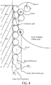
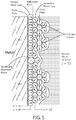
- Bockris, Devanathan, and Muller who take into account solvent interactions in the dielectric.
- This model (illustrated in FIG. 5 ) is yet imperfect and operates on assumptions such as the approximation of ions as point charges, the constancy of dielectric permittivity, the constancy of viscosity, and the assumption that the significant interactions are all Coulombic in nature.
- Bockris, Devanathan and Muller suggested that reorientation of solvent molecules would occur depending on the excess charges at the electrode and the presence or absence of specifically adsorbed ions at the surface.
- the proposed variation of the electrostatic potential with distance is qualitatively similar to that of the Grahame model. Water molecules cover most of the electrode in an oriented layer.
- the water molecules are replaced by a specifically adsorbed ion (e.g., an anion) that has shed its hydration shell.
- a specifically adsorbed ion e.g., an anion
- the plane going through the center of these ions is the inner Helmholtz plane, defining the inner Helmholtz layer.
- Ions that carry a primary hydration shell are found next to and are situated outside of the first layer of water molecules adsorbed onto the electrode surface.
- the plane going through the centers of these ions constitutes the outer Helmholtz plane, defining the outer Helmholtz layer. None of these models teach or suggest an energy storage device with an insulating layer or a variable viscosity dielectric according to principles of the invention.
- the energy that is stored in the diffuse outer layers of an EDLC is often not fully recovered.
- the electrical double layers that are formed close to the electrode surface are termed Helmholtz layers, while those that are further away are termed the Gouy-Chapman layers.
- Helmholtz layers The electrical double layers that are formed close to the electrode surface are termed Helmholtz layers, while those that are further away are termed the Gouy-Chapman layers.
- One distinction between these layers is that the ionic layers that are not capable of being thermally diffused from the electrical surface are termed "Helmholtz" layers. These layers are essentially immobilized at the working temperature by the application of an electric potential to the surface.
- the diffuse Helmholtz layers (Gouy-Chapman, but often referred to as Diffuse Helmholtz layers), referred to as DH layers herein, are layers wherein random thermal movements are able to diffuse the ionic arrangements induced by the electric field. Since this is not a sharp boundary, an arbitrary time
- Both the Helmholtz and DH layers are entropically reduced as compared to the bulk.
- These entropically modified materials display different physical characteristics that have been noted (e.g. permittivity).
- Application of the modified characteristics has been shown in U.S. Patent No. 8,633,289, to be issued January 21, 2014 , which describes improved synthesis of the stable intermediate dimer of xylylene ([2,2']paracyclophane) and derivatives related to that compound and general structure, a method for the formation of cyclophanes and related compounds with various substituents, and a method to apply the xylylene (or substituted xylylene) monomers to make coatings and other polymer products derived from the reactive intermediate.
- US Patent Application No. 13/853,712 published as U.S. Publication No. 2013-0224397 on August 29, 2013 , describes, inter alia, a method for making high permittivity dielectric material for capacitors using organic polymers to produce low conductivity dielectric coatings.
- the rearrangement of the dipoles and ions in an electric field is not as certain to cause a rearrangement of all the other ions and dipoles in the materials. In other words, there is a probability that the rearrangement of the dipole or the ion can take place with little or no net interaction with the other dipoles and ions in the material. In these cases, the material will display less energy storage capability than in its entropically reduced form.
- the viscosity of the material is such that movement of the molecules is able to take place, the energy stored from the formation of the electric field by a given dipole or ion is able to dissipate through relaxation mechanisms in which the energy is converted into rotation, vibration, translation, and other movements that manifest themselves externally as heat. With a low viscosity material, the energy that has been stored in the Diffuse Helmholtz layers (DH layers) is thus lost due to random motions of the ions and dipoles.
- DH layers Diffuse Helmholtz layers
- the time frame for formation of the Helmholtz layers (H layers) and the DH layers is substantially increased.
- the thermal motions of molecules excluding for now vibrations of the lattice as a macroscopic phenomenon), however, are effectively reduced to near negligibility.
- Thermal dissipation is essentially a first order decaying exponential in time similar to radioactive decay or diffusion; if during the charging cycle the energy is absorbed over a time period of, for example, 1 second, a high viscosity material may require many seconds or even minutes to reach even 90% energy dissipation as heat.
- the thermal decay process is substantially slower than the electrical double layer energy storage process.
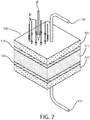
- an energy storage device includes a conductive electrode 105 having a smooth or rough surface, which, by example, may be comprised of a smooth metal, a conductive polymer or a rough carbon electrode of high surface area.
- a resistive or insulative coating 110 is applied to one surface of the electrode 105.
- the coating 110 may comprise a metal oxide, PuraleneTM, plasma or film coating.
- PuraleneTM is applicant's trademark for the coating substance described below.
- a dielectric material 115 i.e., a high permittivity material or a dipole containing low viscosity material, is applied to the outer surface of the coating 110.
- the dielectric material 115 may comprise a conductive or nonconductive polymer, an inorganic metal oxide, mixed metal oxides, mixed polymer and organic materials and biopolymers. Nonlimiting examples of other suitable dielectric compositions are described below.
- the low viscosity of the dielectric may be increased in a controlled manner by application or removal of energy in the form of heat, a force, electric field, magnetic field or other means of changing viscosity of the applied dielectric composition.
- the dielectric 115 may have its viscosity reduced to aid in the more rapid release of the energy from the bound dipole and ionic layers.
- An opposite conductive electrode 125 (which may be comprised of a conductor with insulative or resistive coating or without such a coating) is applied to the dielectric 115, i.e., the high permittivity material or dipole containing low viscosity material.
- the opposite electrode 125 may be the same material as the first electrode 105.
- An insulative or resistive coating 120 between the opposite conductive electrode 125 and the dielectric 115 is optional. This coating 120 may be the same as the coating 110 between the first electrode 105 and the dielectric 115.
- the electrodes may be attached to a voltage source, via conductive leads 130, 135 (e.g., conductive wire leads, traces or other pathways), and allowed to charge.
- conductive leads 130, 135 e.g., conductive wire leads, traces or other pathways
- the viscosity of the dielectric 115 thus charged is optionally increased to allow for a longer period of electric charge storage due to the resulting decrease in random thermal motions or other viscosity-dependent processes.
- the dielectric is discharged by current flow out of the electrodes 105, 125 by an electrical load.
- PET polyethylene terphthalate
- a PuraleneTM coating is preferred due to its characteristics of reduced pinholes, i.e., being substantially nonporous, and its ability to be coated into very thin layers. This enables the overall thickness of a capacitor to be in the range of 100 microns and reasonable voltages are thus possible.
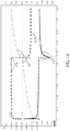
- FIG. 14 illustrates the differences in performance of an energy storage device according to principles of the invention, in contrast to that of a conventional EDLC and batteries.
- Viscosity modifiers such as solvents, branched polymers, low molecular weight oligomers, and dendritic polymers may be added to the dielectric material 115 to reduce viscosity. Ethanol and unreacted starting materials may serve such purposes.
- One non-limiting example of a method for controlling the viscosity of the dielectric is by controlling the temperature. If instead of maintaining the device described above at a constant temperature, during or after charging the device is cooled from an electrode 105 or 125 inward, then the viscosity of the dielectric can be made to gradually increase from electrode layer 105 to electrode layer 125 sequentially, or vice versa. Assuming a viscosity increase with lower temperature (although the opposite effect can sometimes be obtained) the discharge of the H and DH layers as thermal energy can be slowed and essentially halted with complete solidification. The electrical energy can thereby be stored for extended periods of time until ready for release.
- the cooled device can be warmed as necessary with ambient heat or generated heat to release electrical energy through the electrodes as the viscosity of the internal dielectric is reduced. This slow warming has the added benefit of preventing rapid discharge of the energy contained in the H and DH layers. Coordination of the warming of the electrodes and dielectric can be made to accommodate the energy demands of the electrical load. Care must be taken in the system design in order to prevent a runaway condition in which internal or external heating of the dielectric causes the temperature to rise rapidly and in turn decrease viscosity at an increasing, uncontrolled rate.
- a Bingham plastic is a viscoelastic material that behaves as a rigid body at low stresses but flows as a viscous fluid at high stress. More specifically, a Bingham plastic is known to act as a solid when applied stress is below a given limit, and therefore has a measurable yield stress or other factors. By manipulation of this feature, a dielectric which acts as a Bingham plastic could be held in a solid state under low-stress conditions, preserving H and DH layer formations for an extended period of time. When it becomes necessary to release the energy stored within said layers, a varying amount of stress would be applied to the dielectric, thereby controllably lowering it's viscosity.
- the makeup of the dielectric could be chosen such that it exhibits a desirable set of non-Newtonian fluid characteristics.
- the embodiment of the device could then be engineered such that stress could be applied through mechanical or other means to appropriately control the viscosity of the dielectric.
- the capacitor stack could be placed between two plates. The bottom plate would be fixed in place, while the top plate is attached to a mechanical, electromagnetic, hydraulic, or pneumatic actuator. When it becomes desirable to apply stress to the material, the actuator could apply force in a linear or rotational direction so as to apply the optimal amount, rate, and combination of shear and normal stresses deemed most suitable to the fluid application.
- Alternative methods include using a hydraulic or pneumatic bladder to apply stress on the capacitor stack between two fixed plates, as well as surrounding the device with a shape memory alloy, electroactive ceramic, dielectric elastomer, or other active element.
- a combination of these effects may also be used to effect a change in the dielectric's viscosity.
- the capacitor forms what is known as an electroactive polymer or specifically a dielectric elastomer actuator. Once a charge is applied to this capacitor, the electrostatic force between the electrodes causes a force directed normal to both plates. This force effectively "squishes" the dielectric together, applying a normal stress to the dielectric. If this dielectric were also a non-Newtonian shear thickening fluid, the viscosity would increase as the applied shear stress increases.
- the viscosity of the dielectric material could also be dynamically controlled by the modification of its physical characteristics to enhance the dielectric's viscoelectric properties.
- a viscoelectric or electro-rheological fluid the makeup and structure of the dielectric fluid causes enhanced reactivity to external electric fields.
- An applied electric field can cause extreme, rapid, and reversible changes in viscosity.
- Electrorheological fluids can behave as a Bingham plastic, described previously, such that the yield stress is proportional to the applied electric field.
- the design of the electrode has been shown to increase electro-rheological effects.
- the dielectric may be designed to exhibit magneto-rheological effects, which will respond to a magnetic field rather than an electric one. The magneto-rheological effects may be even more applicable through lack of interference with the energy storage mechanism of the device.
- one 105 or both electrodes 105, 125 may be coated using a PuraleneTM coating process.
- a PuraleneTM coating process e.g., a plasma coating process.
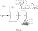
- Sections, referred to as chambers may comprise tanks having an inlet and an outlet or tubular structures with an inlet and an outlet.
- Chamber 210 is a heated tube or other evaporation device intended to volatilize starting material feed 200.
- Starting material feed 200 is evaporated and mixed with inert gas 205 in chamber 210.
- Inert gas 205 may be any of a group, or a mixture of, inert or essentially inert gases, such as, but not limited to, argon or nitrogen. Substitution of nitrogen for argon and/or other essentially inert gases is possible. Pumps and valves may be used to propel and control the flow of fluids from one station to another.
- chamber 210 may comprise an electrically heated Inconel (nickel alloy 600) pyrolysis reaction tube.
- the tube is heated to a temperature of about 450°C to 630°C at atmospheric pressure.
- a flowing stream of argon gas alone, or with a reactive compound such as nitrous oxide, is supplied to the pyrolysis reaction tube.
- the starter material feed 200 may be xylene vapor (Aldrich #134449-4L). If the carrier gas 205 includes a reactive species or compound (e.g., N 2 O), the ratio of gases is adjusted to provide approximately molar stoichiometric ratios of 1:1 of the reactive species or compounds (xylene to nitrous oxide).
- a reactive species or compound e.g., N 2 O
- the heated starter material 200 in the volatile mixture with inert gas reacts with monatomic oxygen in reaction chamber 215. Being very reactive and transient, monatomic oxygen must be available to react with the volatile mixture in the reaction chamber 215.
- the source of monatomic oxygen may be a gaseous compound supplied with the carrier gas 205, or a gaseous compound supplied separately 240, or another source, such as a plasma generator 235.
- Monatomic oxygen plasma may be created by exposing oxygen (O 2 ) gas to an ionizing energy source, such as an RF discharge, which ionizes the gas.
- an ionizing energy source such as an RF discharge
- a compound such as Nitrous Oxide (N 2 O) may supply monatomic oxygen for the reaction through thermal, catalyzed, and/or other decomposition.
- a monatomic oxygen plasma generator 235, or a monatomic oxygen chemical compound (e.g., N 2 O) feed 240, or another suitable source of monatomic oxygen is provided.
- a plasma gas can be used with the aforementioned starting materials to form the intermediate oxidized products that may subsequently react to form reaction products that are oxidized forms of the starting materials which may be monomers, dimers, trimers, oligomers, or polymers.
- the plasma generator 235 includes a gas feed 230 that supplies gas to a plasma reaction chamber 220.
- a plasma driver 225 provides energy to ionize the gas.
- the ratio of gases is adjusted to provide approximately molar stoichiometric ratios of 1:1 (xylene to nitrous oxide or xylene to monatomic oxygen).
- increased amounts of nitrous oxide result in partial and/or complete oxidation of xylene with reduced formation of the desired cyclophane or its polymer. Close control of the stoichiometric ratios of the reactants is desired in this reaction.
- the reaction products are supplied to a reaction chamber 235, which is heated to approximately 450° C to 800° C to facilitate vaporization of the reaction products.
- the vaporized reaction products 245 are expelled onto a lower temperature collection surface 250, where the reaction products condense and form a solid.
- the output of the reaction chamber 235 is sufficiently hot enough to maintain the monomer p-xylylene in monomeric form.
- Rapidly cooling of the monomer onto a surface 250 results in a liquid condensation of the monomer and rapid polymerization of the monomer into a polymer.
- a surface 250 which, such surface, may comprise a surface of an electrode 105, 125
- Comparison of the film thus produced appears to be identical to parylene film formed by the conventional vacuum pyrolysis of dimers produced by the Gorham process. Without augmentation of the PuraleneTM polymer, permittivity of both solidified products is about 3, electric breakdown strengths are about identical at 100 V/micron, and solubility in both hot and cold solvents are below detectable levels.
- the reactive p-xylylene reactive intermediate is formed and subsequently may be dimerized in the reaction tube 235 or during condensation 245 onto the substrate 250.
- This reaction used to synthesize the dimer results in a vast improvement in the overall synthesis yield of the dimer and also results in a vast improvement in the purity of the dimer directly from the reaction. It is understood that variation in the stoichiometric amounts of the reactants may be adjusted to provide for greater or lesser yield with associated purities varying to provide a more economical process or better overall production efficiency without substantially deviating from the scope of this invention. Subsequent purifications of the materials from this reaction can be performed on this material in a manner that is much easier to accomplish than with previously taught processes. The reaction is shown below.
- the deposition of the xylylene monomer can proceed directly onto a solid substrate target without necessity for isolating the intermediate dimer.
- Deposition of the exit gas at above 650°C reaction temperature upon a cool glass plate resulted in formation of an ethanol insoluble substance that displays characteristics of a parylene polymer.
- solubility characteristics clearly show that the material is insoluble in all common solvents (i.e. hexane, xylene, ethyl acetate, ethanol, water).
- Nitrous oxide is an energetically unstable molecule that can be thermally decomposed at elevated temperatures. Products of the reaction are diatomic nitrogen and monoatomic oxygen. The monoatomic oxygen is able to react with itself to form diatomic oxygen, but this reaction is relatively slow. Estimates vary determining the temperature that pure thermal decomposition occurs, but estimates of 1100° C are often cited. Catalysis of this reaction as shown below in equation 1 is known to occur with a variety of metal oxides and mixed metal oxides. Some temperatures used for nitrous oxide decomposition with certain catalysts are as low as 350° C.
- the reactive species for the process is very likely the monoatomic oxygen produced from the decomposition of the nitrous oxide.
- the nitrous oxide can be viewed as a convenient carrier for the delivery of the reactive intermediate, monoatomic oxygen.
- reaction with monoatomic oxygen produced in this manner thus proceeds in a manner similar to that of the nitrous oxide decomposition route.
- Cooling of the elevated temperature gases 245 exiting from the reaction tube 235 is necessary. If the reaction gas is at too high of a temperature, the ability of the reactive intermediate to condense and adhere to a surface is greatly reduced. To this end, a device to mix cool nonreactive or inert gases into the hot reaction stream has been devised.
- the reaction may proceed at increased or decreased pressure (above or below atmospheric pressure). Accordingly, an expansion valve may be used at the exit of the reaction tube 235 to provide Joule-Thomson effect cooling of the hot gas when the gas is below its inversion temperature.
- the method may be extended to other substituents such as the ones shown below.
- Substituents such as the ones noted above (chloro, dichloro, methoxy, and methyl) are not the only aromatic substituents that are capable of being modified by this process into reactive intermediates and their subsequent polymers. Additionally, paracyclophanes and compounds derived thereof are not exclusive to this process. Meta and ortho orientation of the substituents on the aromatic rings are also viable reaction starting materials.
- the reaction can be generalized to include all compounds that are capable of reaction with monatomic oxygen produced from a plasma or from decomposed oxygen-containing substances or its intermediate reaction products and also contain hydrogen atoms stabilized by the presence of an aromatic ring. Typically such hydrogen atoms are located in a position alpha to a phenyl ring (benzylic position).
- Michael structures removed from the alpha aromatic ring positions are known to give similar reactivity to the hydrogen alpha to the aromatic ring position as is well known to those versed in organic synthesis.
- the reactivity of such hydrogen atoms is not limited to alpha and/or Michael positions from an aromatic ring or the aromatic ring such as benzene.
- Other aromatic stabilizations are known for many different rings, fused rings, and non-ring systems, as known to those versed in the art of organic chemistry.
- Such starting materials may preferably have the presence of two hydrogen atoms that are capable of being removed to form partially oxidized starting materials. These preferred materials may optionally have the ability to dimerize, trimerize, oligiomerize, or polymerize.
- the nonlimiting example used herein is p-xylene.
- One implementation of the invention augments permittivity of the polymer by exposing the condensing reaction products 245 to a magnetic or electric field.
- the gaseous stream of reaction product 245 is directed to a cool solid surface 250.
- the surface target 250 may be immersed in a magnetic field 255 such as that provided by a Neodymium magnet (S84, K&J Magnetics).
- a Neodymium magnet S84, K&J Magnetics
- Other magnetic field sources may be utilized and are intended to come within the scope of the invention.
- Condensation of the monomer and subsequent polymerization can proceed rapidly while in the magnetic field 255. If the target and the magnet maintain the same relative orientation during the polymerization process, then a baseline increase in the electrical permittivity has been shown to occur. If the orientation of the magnetic field 255 relationship to the target is rotated during the polymerization or solid phase condensation process, then the resulting permittivity has been shown to decrease.
- the relative permittivity of the material deposited is approximately 3.
- the relative permittivity is approximately 7.
- the magnetic field has been shown to substantially increase the permittivity of the product by over a factor of 2 times.
- other salts, dipoles, and salts of organic acids can be entropically oriented during solidification or polymerizations to produce enhanced high permittivity materials. Improvements in permittivity from 10 to over 1000% may be attained.
- the surface target 250 is immersed in an electric field 255 such as that provided by a high voltage power supply (G40, Emco, 4000V). Condensation of the monomer and subsequent polymerization can proceed rapidly while in the electric field. If the target and the electric field maintain the same relative orientation during the polymerization process, then a baseline increase in the electrical permittivity has been shown to occur. If the orientation of the electric field relationship to the target is rotated during the polymerization or solid phase condensation process, then the resulting permittivity has been shown to be lower.
- an electric field 255 such as that provided by a high voltage power supply (G40, Emco, 4000V). Condensation of the monomer and subsequent polymerization can proceed rapidly while in the electric field. If the target and the electric field maintain the same relative orientation during the polymerization process, then a baseline increase in the electrical permittivity has been shown to occur. If the orientation of the electric field relationship to the target is rotated during the polymerization or solid phase condensation process, then the resulting permittivity has been shown
- Condensation of dielectric reaction products in the presence of an electric and/or magnetic field has been shown to augment the permittivity of the condensed dielectric. This step may be applied to compounds other than parylene polymers.
- the relative permittivity of the material deposited is approximately 500.
- the relative permittivity is approximately 25000 to 40000.
- the electric field has been shown to substantially increase the permittivity of the dielectric field by at least a factor of 25 in that particular case.
- other salts, dipoles, and salts of organic acids can be entropically oriented during solidification or polymerizations to produce enhanced high permittivity materials. Improvements in permittivity have been shown to range from 5 to over 10000%.
- the thickness of a PuraleneTM coating 110, 120 may range from 5 to 30 nm to greater than 10 microns.
- the coated electrode 105, 125 is then used as the basis for application of the dielectric material 115.
- Dielectrics that may be used to form a capacitor according to principles of the invention abound. However, to produce a substantially improved energy storage device, it requires more than simply making a dielectric and putting it between two electrodes.
- a viscosity stratified dielectric for an energy storage device may be formed from 15 grams of protein powder (such as Zein, Sigma-Aldrich #Z3625), to which 50 ml of absolute ethanol is added. The solution is well stirred under inert atmosphere until complete dissolution is obtained. To this solution is added portion-wise 10g of maleic anhydride (Sigma-Aldrich #M188) solid with vigorous stirring for a total period of 30 min. The solution is heated to 60° C during this period of time. At the end of the period 0.5 g of dicumylperoxide (Sigma-Aldrich #329541) is added portion-wise over 5 min.
- protein powder such as Zein, Sigma-Aldrich #Z3625
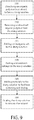
- FIG. 9 is an exemplary flow chart illustrating a method for making a high permittivity dielectric material, according to an embodiment of the present disclosure.
- the method begins by dissolving an organic polymer in a solvent to form a slurry solution (305).
- the polymer may be shellac, silicone oil, zein, and/or another organic polymer.
- the undissolved organic polymer is removed from the slurry solution (310), for non-limiting example, using a filter or centrifuge.
- An inorganic salt may then be added to the slurry solution (315).
- the inorganic salt may be a transition metal salt, such as a Gd, Sr, Sn, Fe salt, or a mixture thereof.
- a breakdown voltage adjuvant may be added to the slurry solution (320).
- the breakdown voltage adjuvant may include one or more of Y, Ni, Sm, Sc, Tb, Yb, La, Te, Ti, Zr, Ge, Mg, Pb, Hf, Cu, Ta, Nb, Bi, or a mixture thereof.
- a dimethyl formamide and a dimethylsulfoxide may be added to the slurry solution (325).
- the slurry solution may then be heated to a temperature of about 150° C to about 300° C to remove or evaporate the solvent (330). This method avoids high process temperatures and produces a high dielectric capacitor with a high breakdown voltage.
- dielectric materials include conductive polymers salts, such as salts of acrylic acid, acrylamides, methacrylates, polypyrole, etc.; inorganic metal oxide such as perovskites (i.e. barium titanate, strontium barium titanate, etc.); charged ionic liquids such as polymer salts and other electrically charged liquids or semi-solids that may have ability to migrate or move to some extent within a matrix; or a mixture of these.
- conductive polymers salts such as salts of acrylic acid, acrylamides, methacrylates, polypyrole, etc.
- inorganic metal oxide such as perovskites (i.e. barium titanate, strontium barium titanate, etc.)
- charged ionic liquids such as polymer salts and other electrically charged liquids or semi-solids that may have ability to migrate or move to some extent within a matrix; or a mixture of these.
- the applied dielectric material 115 has a second electrode 125 added that may be optionally coated with a nonconductive coating 120 such as PuraleneTM, using a coating process as described above. Connection of the electrodes 105, 125 to a voltage source and a load via leads 130, 135 is similar to that of a traditional electrostatic capacitor.
- a nonconductive coating 120 such as PuraleneTM
- a high surface area electrode 105, 125 is used instead of a smooth electrode. This provides for a greater surface capacitance and a faster discharge during the first phase of discharge.
- the high surface area electrode may comprise activated carbon or another conductive material which, when applied to the surface of the electrode, exhibits high surface area.
- the adjacent electrode may be coated or uncoated.
- an energy storage device may contain a dielectric material that has the property of changing viscosity.
- the methods for introduction of variable viscosity into the dielectric may comprise variable temperature, variable electric field, variable magnetic field, variable pressure, variable shear and/or normal stress.
- Variable pressure, shear and stress are each a type of application of force. The direction and distribution of the applied force determines whether it is a pressure, shear or stress.
- An exemplary method of making a magnetorheological dielectric entails distributing electrically insulated (or non conducting) magnetic particles throughout the dielectric. Once the H and DH layers are formed, a magnetic field would be applied to increase the viscosity of as well as to prevent particle migration through the dielectric and "lock in” the H and DH layers. Altering the magnetic field strength would allow controlled dissociation of the layers through charge migration (current flow) within the dielectric itself. Also, the applied magnetic field could potentially introduce additional layering or entropic changes for energy storage.
- the capacitance-mode of the device In general the largest mechanism for the initial charging current into the energy storage devices noted above are through the capacitance-mode of the device. During the later energy storage phase of charging, the diffuse Helmholtz layer formations is the primary mode of energy storage. This DH mode is more easily accomplished when the dielectric material is less viscous. This general rule is tempered by the fact that certain polymers can display more viscous characteristics while under an electric field than not. However, the formation of the DH layers is more pronounced when the device is under a greater electric field. To prevent the dissipation of energy stored in the DH layers, it desirable to have the viscosity increase after the electrical energy has been used to form these layers. In this way dissipation of the energy is decreased and potentially mitigated.
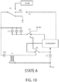
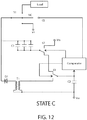
- FIGs. 10-13 a multi-state electrical circuit diagram is illustrated in various states in accordance with one or more embodiments for making an electronic device for the recovery of leakage current from an energy storage capacitor.
- FIGs. 10-13 illustrates four states a novel circuit that has been developed to regenerate and recycle the leakage current from a capacitor or capacitor array, C1.
- C1 is a capacitor or capacitor array that is capable of storing a certain amount of charge. It displays a leakage of current when subjected to a given voltage (V+).
- C2 is a capacitor (e.g., much smaller than C1) of good storage characteristics that displays a much lower leakage current (or could be the same leakage current, but of much smaller area of capacitance).
- D1 is a diode that has the characteristic of being able to "block" the voltage from C1 from returning to Vss. When the voltage output from transformer T1's secondary coil exceeds the voltage present on C1 and the forward voltage drop of D1, then current will conduct to the C1 capacitor(s).
- S1 is a three position single pole switch.
- Line CL is a control line that controls S1.
- S1 is switch that is able to electrically connect the high voltage side of C1 to the charging voltage, V+. In one position it is connected to V+ and in the other position it is an open connection (NC) or connected to the load (LOAD).
- S2 and S3 are electrically controlled switches that have the ability to switch between two different outputs. These switches do not necessarily need to be high voltage switches able to withstand V+.
- T1 is a "flyback" type of transformer or an equivalent inductor that has the capability of withstanding a voltage on the secondary winding that is as great or greater than V+.
- V+ is a charging voltage that is connected to the main energy storage capacitor(s) C1 during the charge cycle.
- Vss is the lower voltage that is present on the opposite electrode of C1 from V+that produces the potential difference between the two electrodes.
- leakage current may be recovered and regenerated from a capacitor C1 according to principles of the invention.
- State A of the circuit diagram of FIG. 10 a current is shown flowing from the V+ source through S1 to the positive plate of C1.
- S2 is connected to Vss such that the charge can be accumulated on C1 to the potential difference between the two.
- the status of S3 does not matter at this state and no current is flowing in the lower part of the circuit.
- the comparator then disconnects C2 from C1's open "Vss” electrode using S2, and S2 connects to "Vss", and then subsequently connects the positive electrode of C2 to the input of T1 transformer using S3, as shown in State D of FIG. 13 .
- This discharge current through T1 induces a voltage on the secondary of T1 that rises to a voltage value sufficient to return some of the charge to C1 through the diode D1.
- a relatively “leaky” capacitor can return some of the charge loss through the C1's leakage when C1 is not in use during either a charge or discharge period of time. Due to the efficiency of the circuit (which can be made to be >90% efficiency), the leakage from the C1 device is effectively reduced by a factor of up to 9 times. For production of a large array of capacitors, this can be a significant improvement in yield. Often there are unwanted impurities in the material that increase the leakage current, and these are often not detected until the entire assembly has been completed. In the case of a large array capacitor, this amounts to a significant number of good devices being rejected due to a relatively small number of failures in the array.
- a voltage charges one electrode of the energy storage device, while a voltage is generated by the other electrode that is series connected to ground through a 10K resistor.
- the device charges, there is a rapid charging of the electrode and low impedance due to the capacitance of the device.
- the capacitance modes of charging are much faster than the Helmholtz layer formations, but ultimately much less charge is stored by these mechanisms for energy storage than by the DH layer formations.
- the energy storage device is a capacitor that charges through a resistor coupled to a 120VDC source. Connection of a PicoScopeTM Model 4262 to each electrode of the capacitor and utilization of the scope's integrated math functions allow calculation and display of the energy flowing into the circuit as shown by trace 405.
- the applied voltage to the first electrode is represented by trace 415A-415B, and the displacement current is represented by the trace 410.
- the first charging voltage of approximately 120V supplies 8.16J to the capacitor.
- the second voltage of -120VDC applied at approximately the 3 minute mark shows an energy delivery of 8.08J. In this particular charge sequence the amount of charge and discharge are approximately equal.
- Integration of the displacement current across the capacitor reveals that the energy absorbed and the energy discharged are approximately equal to within the error limits of the data acquisition device and integration routine. Longer charge cycles could be used, but essentially all of the energy supplied in this period of time at this voltage has been absorbed by the capacitor in this time frame. Some droop in the power supplies are present due to the low reactance of the capacitor during initial switching. This voltage drop is accounted for in the calculations of the scope.
- the energy absorbed is 8.16J.
- the volume of sample is 0.006333 ml.
- the energy density is 1288 J/ml or 198 Wh/kg. Integration of the charge reveals that essentially a >90% recovery of the charge can be obtained when the discharge cycle is at least 10 times longer than the charge cycle.
- the charge stored is in the range of 0.41 Wh/kg at very low electric field magnitudes (.34 V per micron).
- Table 2. q C A d v E Vol. E/m 3 ⁇ E/kg E-field 776,000 25,876 50 87 30 1.16E-2 4.35E-9 2.68E+6 1.8 0.413 0.34 q in (nA.s), C in ⁇ F, A in mm 2 , d in ⁇ m, v in volts, E in J, Vol. in m 3 , ⁇ in g/cm 3 , E/kg in Wh/kg, E-field in V/ ⁇ m.
Landscapes
- Engineering & Computer Science (AREA)
- Power Engineering (AREA)
- Microelectronics & Electronic Packaging (AREA)
- Chemical & Material Sciences (AREA)
- Chemical Kinetics & Catalysis (AREA)
- Electrochemistry (AREA)
- Electric Double-Layer Capacitors Or The Like (AREA)
- Fixed Capacitors And Capacitor Manufacturing Machines (AREA)
Applications Claiming Priority (4)
| Application Number | Priority Date | Filing Date | Title |
|---|---|---|---|
| US13/853,712 US9011627B2 (en) | 2007-10-05 | 2013-03-29 | Method of manufacturing high permittivity low leakage capacitor and energy storing device |
| US201361808733P | 2013-04-05 | 2013-04-05 | |
| US14/156,457 US8940850B2 (en) | 2012-08-30 | 2014-01-16 | Energy storage device |
| PCT/US2014/033102 WO2014161007A2 (en) | 2013-03-29 | 2014-04-04 | Energy storage device |
Publications (3)
| Publication Number | Publication Date |
|---|---|
| EP2979284A2 EP2979284A2 (en) | 2016-02-03 |
| EP2979284A4 EP2979284A4 (en) | 2017-03-29 |
| EP2979284B1 true EP2979284B1 (en) | 2021-05-26 |
Family
ID=51625697
Family Applications (1)
| Application Number | Title | Priority Date | Filing Date |
|---|---|---|---|
| EP14774940.2A Active EP2979284B1 (en) | 2013-03-29 | 2014-04-04 | Energy storage device |
Country Status (5)
| Country | Link |
|---|---|
| EP (1) | EP2979284B1 (enExample) |
| JP (1) | JP6526624B2 (enExample) |
| AU (1) | AU2014240816B2 (enExample) |
| SG (1) | SG11201507993RA (enExample) |
| WO (1) | WO2014161007A2 (enExample) |
Families Citing this family (9)
| Publication number | Priority date | Publication date | Assignee | Title |
|---|---|---|---|---|
| US9011627B2 (en) | 2007-10-05 | 2015-04-21 | Carver Scientific, Inc. | Method of manufacturing high permittivity low leakage capacitor and energy storing device |
| WO2009046341A1 (en) | 2007-10-05 | 2009-04-09 | David Carver | High permittivity low leakage capacitor and energy storing device and method for forming the same |
| US8940850B2 (en) | 2012-08-30 | 2015-01-27 | Carver Scientific, Inc. | Energy storage device |
| US9214280B2 (en) | 2008-10-03 | 2015-12-15 | Carver Scientific, Inc. | Very thin dielectrics for high permittivity and very low leakage capacitors and energy storing devices |
| US9214281B2 (en) | 2008-10-03 | 2015-12-15 | Carver Scientific, Inc. | Very thin dielectrics for high permittivity and very low leakage capacitors and energy storing devices |
| US10227432B2 (en) | 2011-08-31 | 2019-03-12 | Carver Scientific, Inc. | Formation of xylylene type copolymers, block polymers, and mixed composition materials |
| US10199165B2 (en) | 2012-08-30 | 2019-02-05 | Carver Scientific, Inc. | Energy storage device |
| US9805869B2 (en) | 2012-11-07 | 2017-10-31 | Carver Scientific, Inc. | High energy density electrostatic capacitor |
| CN110431647B (zh) | 2016-12-02 | 2022-06-28 | 卡弗科学有限公司 | 存储设备和电容储能设备 |
Family Cites Families (20)
| Publication number | Priority date | Publication date | Assignee | Title |
|---|---|---|---|---|
| US2798990A (en) * | 1952-11-22 | 1957-07-09 | Sprague Electric Co | Electrical capacitors |
| US3535602A (en) * | 1969-05-07 | 1970-10-20 | Nasa | Capacitor and method of making same |
| JPH07190098A (ja) * | 1993-12-28 | 1995-07-28 | Tonen Corp | 電 極 |
| JPH07310774A (ja) * | 1994-05-18 | 1995-11-28 | Fuji Polymertech Kk | 可変減衰性流体ダンパ用電極 |
| JPH0963905A (ja) * | 1995-08-29 | 1997-03-07 | Matsushita Electric Ind Co Ltd | 電気二重層キャパシタおよびその製造方法 |
| JPH0987647A (ja) * | 1995-09-21 | 1997-03-31 | Asahi Chem Ind Co Ltd | 電気粘性流体 |
| JPH10122266A (ja) * | 1996-10-14 | 1998-05-12 | Asahi Chem Ind Co Ltd | 電気粘性流体用電極 |
| WO2004087608A1 (ja) * | 2003-03-31 | 2004-10-14 | Tdk Corporation | 電極段差吸収用印刷ペーストおよび電子部品の製造方法 |
| US7413815B2 (en) * | 2004-02-19 | 2008-08-19 | Oak-Mitsui Inc. | Thin laminate as embedded capacitance material in printed circuit boards |
| US20080171230A1 (en) * | 2004-02-27 | 2008-07-17 | Qin Zou | Thin Film Ferroelectric Composites, Method of Making and Capacitor Comprising the Same |
| US7287415B2 (en) * | 2004-09-30 | 2007-10-30 | Teledyne Licensing, Llc | Microelectromechanical system (MEMS) viscosity sensor for fluid health monitoring |
| US7429317B2 (en) * | 2004-12-20 | 2008-09-30 | Eksigent Technologies Llc | Electrokinetic device employing a non-newtonian liquid |
| US20070108490A1 (en) * | 2005-11-14 | 2007-05-17 | General Electric Company | Film capacitors with improved dielectric properties |
| JP4882457B2 (ja) * | 2006-03-31 | 2012-02-22 | 富士通株式会社 | 薄膜キャパシタおよびこれを有する半導体装置 |
| US8236191B2 (en) * | 2007-01-12 | 2012-08-07 | Daikin Industries, Ltd. | Electrical double layer capacitor |
| JP4611323B2 (ja) * | 2007-01-26 | 2011-01-12 | 富士通株式会社 | 可変キャパシタ |
| US8382042B2 (en) * | 2008-05-14 | 2013-02-26 | Raytheon Company | Structure with reconfigurable polymer material |
| ITMI20090917A1 (it) * | 2009-05-25 | 2010-11-26 | Getters Spa | Getter composito multistrato |
| US20120081833A1 (en) * | 2010-09-30 | 2012-04-05 | General Electric Company | Electronic devices containing polyetherimide components |
| KR101735715B1 (ko) * | 2010-11-23 | 2017-05-15 | 삼성전자주식회사 | 입력 감지 소자 및 이를 구비한 터치 패널 |
-
2014
- 2014-04-04 AU AU2014240816A patent/AU2014240816B2/en not_active Ceased
- 2014-04-04 WO PCT/US2014/033102 patent/WO2014161007A2/en not_active Ceased
- 2014-04-04 SG SG11201507993RA patent/SG11201507993RA/en unknown
- 2014-04-04 EP EP14774940.2A patent/EP2979284B1/en active Active
- 2014-04-04 JP JP2016505622A patent/JP6526624B2/ja active Active
Non-Patent Citations (1)
| Title |
|---|
| None * |
Also Published As
| Publication number | Publication date |
|---|---|
| SG11201507993RA (en) | 2015-10-29 |
| AU2014240816A1 (en) | 2015-10-22 |
| AU2014240816B2 (en) | 2018-03-29 |
| WO2014161007A2 (en) | 2014-10-02 |
| WO2014161007A3 (en) | 2014-12-04 |
| JP6526624B2 (ja) | 2019-06-12 |
| JP2016514907A (ja) | 2016-05-23 |
| EP2979284A4 (en) | 2017-03-29 |
| EP2979284A2 (en) | 2016-02-03 |
Similar Documents
| Publication | Publication Date | Title |
|---|---|---|
| US9786442B2 (en) | Energy storage device | |
| EP2979284B1 (en) | Energy storage device | |
| CA2908178C (en) | Energy storage device | |
| US9899846B2 (en) | Entropic energy transfer methods and circuits | |
| EP3235092B1 (en) | Entropic energy transfer methods and circuits | |
| JP2020120130A (ja) | コンデンサ及びその製造方法 | |
| US9916930B2 (en) | Method of manufacturing high permittivity low leakage capacitor and energy storing device | |
| JP2020127044A (ja) | エネルギー蓄積装置及びその製造方法 | |
| US20140295101A1 (en) | High permittivity low leakage capacitor and energy storing device | |
| US9214280B2 (en) | Very thin dielectrics for high permittivity and very low leakage capacitors and energy storing devices | |
| US9214281B2 (en) | Very thin dielectrics for high permittivity and very low leakage capacitors and energy storing devices | |
| KR20150082377A (ko) | 고에너지 밀도 정전 커패시터 | |
| HK1221328B (zh) | 能量储存设备 | |
| Kumari et al. | High dielectric materials for supercapacitors | |
| WO2017093596A1 (en) | An energy storage electrode | |
| US8431037B2 (en) | Liquid composite dielectric material | |
| Sandhu et al. | The Development of Capacitor Materials Technology |
Legal Events
| Date | Code | Title | Description |
|---|---|---|---|
| PUAI | Public reference made under article 153(3) epc to a published international application that has entered the european phase |
Free format text: ORIGINAL CODE: 0009012 |
|
| 17P | Request for examination filed |
Effective date: 20150929 |
|
| AK | Designated contracting states |
Kind code of ref document: A2 Designated state(s): AL AT BE BG CH CY CZ DE DK EE ES FI FR GB GR HR HU IE IS IT LI LT LU LV MC MK MT NL NO PL PT RO RS SE SI SK SM TR |
|
| AX | Request for extension of the european patent |
Extension state: BA ME |
|
| RIN1 | Information on inventor provided before grant (corrected) |
Inventor name: HALL, SEAN Inventor name: CARVER, ROBERT Inventor name: CARVER, DAVID Inventor name: REYNOLDS, SEAN Inventor name: DAVIS, NOAH |
|
| RIN1 | Information on inventor provided before grant (corrected) |
Inventor name: REYNOLDS, SEAN Inventor name: CARVER, DAVID Inventor name: DAVIS, NOAH Inventor name: HALL, SEAN Inventor name: CARVER, ROBERT |
|
| DAX | Request for extension of the european patent (deleted) | ||
| A4 | Supplementary search report drawn up and despatched |
Effective date: 20170224 |
|
| RIC1 | Information provided on ipc code assigned before grant |
Ipc: H01G 11/22 20130101ALI20170220BHEP Ipc: H01G 11/00 20130101ALI20170220BHEP Ipc: H01G 5/00 20060101AFI20170220BHEP |
|
| STAA | Information on the status of an ep patent application or granted ep patent |
Free format text: STATUS: EXAMINATION IS IN PROGRESS |
|
| 17Q | First examination report despatched |
Effective date: 20171011 |
|
| REG | Reference to a national code |
Ref country code: DE Ref legal event code: R079 Ref document number: 602014077732 Country of ref document: DE Free format text: PREVIOUS MAIN CLASS: H01G0005000000 Ipc: H01G0009020000 |
|
| RIC1 | Information provided on ipc code assigned before grant |
Ipc: H01G 11/56 20130101ALI20200929BHEP Ipc: H01G 9/02 20060101AFI20200929BHEP Ipc: H01G 11/52 20130101ALI20200929BHEP Ipc: H01G 9/025 20060101ALI20200929BHEP |
|
| GRAP | Despatch of communication of intention to grant a patent |
Free format text: ORIGINAL CODE: EPIDOSNIGR1 |
|
| STAA | Information on the status of an ep patent application or granted ep patent |
Free format text: STATUS: GRANT OF PATENT IS INTENDED |
|
| GRAJ | Information related to disapproval of communication of intention to grant by the applicant or resumption of examination proceedings by the epo deleted |
Free format text: ORIGINAL CODE: EPIDOSDIGR1 |
|
| STAA | Information on the status of an ep patent application or granted ep patent |
Free format text: STATUS: EXAMINATION IS IN PROGRESS |
|
| INTG | Intention to grant announced |
Effective date: 20201109 |
|
| INTC | Intention to grant announced (deleted) | ||
| GRAP | Despatch of communication of intention to grant a patent |
Free format text: ORIGINAL CODE: EPIDOSNIGR1 |
|
| STAA | Information on the status of an ep patent application or granted ep patent |
Free format text: STATUS: GRANT OF PATENT IS INTENDED |
|
| INTG | Intention to grant announced |
Effective date: 20210113 |
|
| GRAS | Grant fee paid |
Free format text: ORIGINAL CODE: EPIDOSNIGR3 |
|
| GRAA | (expected) grant |
Free format text: ORIGINAL CODE: 0009210 |
|
| STAA | Information on the status of an ep patent application or granted ep patent |
Free format text: STATUS: THE PATENT HAS BEEN GRANTED |
|
| AK | Designated contracting states |
Kind code of ref document: B1 Designated state(s): AL AT BE BG CH CY CZ DE DK EE ES FI FR GB GR HR HU IE IS IT LI LT LU LV MC MK MT NL NO PL PT RO RS SE SI SK SM TR |
|
| REG | Reference to a national code |
Ref country code: GB Ref legal event code: FG4D |
|
| REG | Reference to a national code |
Ref country code: CH Ref legal event code: EP |
|
| REG | Reference to a national code |
Ref country code: DE Ref legal event code: R096 Ref document number: 602014077732 Country of ref document: DE |
|
| REG | Reference to a national code |
Ref country code: AT Ref legal event code: REF Ref document number: 1397050 Country of ref document: AT Kind code of ref document: T Effective date: 20210615 |
|
| REG | Reference to a national code |
Ref country code: IE Ref legal event code: FG4D |
|
| REG | Reference to a national code |
Ref country code: LT Ref legal event code: MG9D |
|
| REG | Reference to a national code |
Ref country code: AT Ref legal event code: MK05 Ref document number: 1397050 Country of ref document: AT Kind code of ref document: T Effective date: 20210526 |
|
| PG25 | Lapsed in a contracting state [announced via postgrant information from national office to epo] |
Ref country code: HR Free format text: LAPSE BECAUSE OF FAILURE TO SUBMIT A TRANSLATION OF THE DESCRIPTION OR TO PAY THE FEE WITHIN THE PRESCRIBED TIME-LIMIT Effective date: 20210526 Ref country code: AT Free format text: LAPSE BECAUSE OF FAILURE TO SUBMIT A TRANSLATION OF THE DESCRIPTION OR TO PAY THE FEE WITHIN THE PRESCRIBED TIME-LIMIT Effective date: 20210526 Ref country code: BG Free format text: LAPSE BECAUSE OF FAILURE TO SUBMIT A TRANSLATION OF THE DESCRIPTION OR TO PAY THE FEE WITHIN THE PRESCRIBED TIME-LIMIT Effective date: 20210826 Ref country code: FI Free format text: LAPSE BECAUSE OF FAILURE TO SUBMIT A TRANSLATION OF THE DESCRIPTION OR TO PAY THE FEE WITHIN THE PRESCRIBED TIME-LIMIT Effective date: 20210526 Ref country code: LT Free format text: LAPSE BECAUSE OF FAILURE TO SUBMIT A TRANSLATION OF THE DESCRIPTION OR TO PAY THE FEE WITHIN THE PRESCRIBED TIME-LIMIT Effective date: 20210526 |
|
| REG | Reference to a national code |
Ref country code: NL Ref legal event code: MP Effective date: 20210526 |
|
| PG25 | Lapsed in a contracting state [announced via postgrant information from national office to epo] |
Ref country code: LV Free format text: LAPSE BECAUSE OF FAILURE TO SUBMIT A TRANSLATION OF THE DESCRIPTION OR TO PAY THE FEE WITHIN THE PRESCRIBED TIME-LIMIT Effective date: 20210526 Ref country code: GR Free format text: LAPSE BECAUSE OF FAILURE TO SUBMIT A TRANSLATION OF THE DESCRIPTION OR TO PAY THE FEE WITHIN THE PRESCRIBED TIME-LIMIT Effective date: 20210827 Ref country code: IS Free format text: LAPSE BECAUSE OF FAILURE TO SUBMIT A TRANSLATION OF THE DESCRIPTION OR TO PAY THE FEE WITHIN THE PRESCRIBED TIME-LIMIT Effective date: 20210926 Ref country code: SE Free format text: LAPSE BECAUSE OF FAILURE TO SUBMIT A TRANSLATION OF THE DESCRIPTION OR TO PAY THE FEE WITHIN THE PRESCRIBED TIME-LIMIT Effective date: 20210526 Ref country code: RS Free format text: LAPSE BECAUSE OF FAILURE TO SUBMIT A TRANSLATION OF THE DESCRIPTION OR TO PAY THE FEE WITHIN THE PRESCRIBED TIME-LIMIT Effective date: 20210526 Ref country code: PT Free format text: LAPSE BECAUSE OF FAILURE TO SUBMIT A TRANSLATION OF THE DESCRIPTION OR TO PAY THE FEE WITHIN THE PRESCRIBED TIME-LIMIT Effective date: 20210927 Ref country code: NO Free format text: LAPSE BECAUSE OF FAILURE TO SUBMIT A TRANSLATION OF THE DESCRIPTION OR TO PAY THE FEE WITHIN THE PRESCRIBED TIME-LIMIT Effective date: 20210826 Ref country code: PL Free format text: LAPSE BECAUSE OF FAILURE TO SUBMIT A TRANSLATION OF THE DESCRIPTION OR TO PAY THE FEE WITHIN THE PRESCRIBED TIME-LIMIT Effective date: 20210526 |
|
| PG25 | Lapsed in a contracting state [announced via postgrant information from national office to epo] |
Ref country code: NL Free format text: LAPSE BECAUSE OF FAILURE TO SUBMIT A TRANSLATION OF THE DESCRIPTION OR TO PAY THE FEE WITHIN THE PRESCRIBED TIME-LIMIT Effective date: 20210526 |
|
| PG25 | Lapsed in a contracting state [announced via postgrant information from national office to epo] |
Ref country code: ES Free format text: LAPSE BECAUSE OF FAILURE TO SUBMIT A TRANSLATION OF THE DESCRIPTION OR TO PAY THE FEE WITHIN THE PRESCRIBED TIME-LIMIT Effective date: 20210526 Ref country code: RO Free format text: LAPSE BECAUSE OF FAILURE TO SUBMIT A TRANSLATION OF THE DESCRIPTION OR TO PAY THE FEE WITHIN THE PRESCRIBED TIME-LIMIT Effective date: 20210526 Ref country code: CZ Free format text: LAPSE BECAUSE OF FAILURE TO SUBMIT A TRANSLATION OF THE DESCRIPTION OR TO PAY THE FEE WITHIN THE PRESCRIBED TIME-LIMIT Effective date: 20210526 Ref country code: EE Free format text: LAPSE BECAUSE OF FAILURE TO SUBMIT A TRANSLATION OF THE DESCRIPTION OR TO PAY THE FEE WITHIN THE PRESCRIBED TIME-LIMIT Effective date: 20210526 Ref country code: DK Free format text: LAPSE BECAUSE OF FAILURE TO SUBMIT A TRANSLATION OF THE DESCRIPTION OR TO PAY THE FEE WITHIN THE PRESCRIBED TIME-LIMIT Effective date: 20210526 Ref country code: SK Free format text: LAPSE BECAUSE OF FAILURE TO SUBMIT A TRANSLATION OF THE DESCRIPTION OR TO PAY THE FEE WITHIN THE PRESCRIBED TIME-LIMIT Effective date: 20210526 Ref country code: SM Free format text: LAPSE BECAUSE OF FAILURE TO SUBMIT A TRANSLATION OF THE DESCRIPTION OR TO PAY THE FEE WITHIN THE PRESCRIBED TIME-LIMIT Effective date: 20210526 |
|
| REG | Reference to a national code |
Ref country code: DE Ref legal event code: R097 Ref document number: 602014077732 Country of ref document: DE |
|
| PLBE | No opposition filed within time limit |
Free format text: ORIGINAL CODE: 0009261 |
|
| STAA | Information on the status of an ep patent application or granted ep patent |
Free format text: STATUS: NO OPPOSITION FILED WITHIN TIME LIMIT |
|
| 26N | No opposition filed |
Effective date: 20220301 |
|
| PG25 | Lapsed in a contracting state [announced via postgrant information from national office to epo] |
Ref country code: IS Free format text: LAPSE BECAUSE OF FAILURE TO SUBMIT A TRANSLATION OF THE DESCRIPTION OR TO PAY THE FEE WITHIN THE PRESCRIBED TIME-LIMIT Effective date: 20210926 Ref country code: AL Free format text: LAPSE BECAUSE OF FAILURE TO SUBMIT A TRANSLATION OF THE DESCRIPTION OR TO PAY THE FEE WITHIN THE PRESCRIBED TIME-LIMIT Effective date: 20210526 |
|
| PG25 | Lapsed in a contracting state [announced via postgrant information from national office to epo] |
Ref country code: IT Free format text: LAPSE BECAUSE OF FAILURE TO SUBMIT A TRANSLATION OF THE DESCRIPTION OR TO PAY THE FEE WITHIN THE PRESCRIBED TIME-LIMIT Effective date: 20210526 |
|
| REG | Reference to a national code |
Ref country code: CH Ref legal event code: PL |
|
| REG | Reference to a national code |
Ref country code: BE Ref legal event code: MM Effective date: 20220430 |
|
| PG25 | Lapsed in a contracting state [announced via postgrant information from national office to epo] |
Ref country code: MC Free format text: LAPSE BECAUSE OF FAILURE TO SUBMIT A TRANSLATION OF THE DESCRIPTION OR TO PAY THE FEE WITHIN THE PRESCRIBED TIME-LIMIT Effective date: 20210526 Ref country code: LU Free format text: LAPSE BECAUSE OF NON-PAYMENT OF DUE FEES Effective date: 20220404 Ref country code: LI Free format text: LAPSE BECAUSE OF NON-PAYMENT OF DUE FEES Effective date: 20220430 Ref country code: CH Free format text: LAPSE BECAUSE OF NON-PAYMENT OF DUE FEES Effective date: 20220430 |
|
| PG25 | Lapsed in a contracting state [announced via postgrant information from national office to epo] |
Ref country code: BE Free format text: LAPSE BECAUSE OF NON-PAYMENT OF DUE FEES Effective date: 20220430 |
|
| PG25 | Lapsed in a contracting state [announced via postgrant information from national office to epo] |
Ref country code: IE Free format text: LAPSE BECAUSE OF NON-PAYMENT OF DUE FEES Effective date: 20220404 |
|
| P01 | Opt-out of the competence of the unified patent court (upc) registered |
Effective date: 20230515 |
|
| PG25 | Lapsed in a contracting state [announced via postgrant information from national office to epo] |
Ref country code: HU Free format text: LAPSE BECAUSE OF FAILURE TO SUBMIT A TRANSLATION OF THE DESCRIPTION OR TO PAY THE FEE WITHIN THE PRESCRIBED TIME-LIMIT; INVALID AB INITIO Effective date: 20140404 |
|
| PG25 | Lapsed in a contracting state [announced via postgrant information from national office to epo] |
Ref country code: MK Free format text: LAPSE BECAUSE OF FAILURE TO SUBMIT A TRANSLATION OF THE DESCRIPTION OR TO PAY THE FEE WITHIN THE PRESCRIBED TIME-LIMIT Effective date: 20210526 Ref country code: CY Free format text: LAPSE BECAUSE OF FAILURE TO SUBMIT A TRANSLATION OF THE DESCRIPTION OR TO PAY THE FEE WITHIN THE PRESCRIBED TIME-LIMIT Effective date: 20210526 |
|
| PGFP | Annual fee paid to national office [announced via postgrant information from national office to epo] |
Ref country code: GB Payment date: 20240307 Year of fee payment: 11 |
|
| PGFP | Annual fee paid to national office [announced via postgrant information from national office to epo] |
Ref country code: FR Payment date: 20240308 Year of fee payment: 11 |
|
| PG25 | Lapsed in a contracting state [announced via postgrant information from national office to epo] |
Ref country code: TR Free format text: LAPSE BECAUSE OF FAILURE TO SUBMIT A TRANSLATION OF THE DESCRIPTION OR TO PAY THE FEE WITHIN THE PRESCRIBED TIME-LIMIT Effective date: 20210526 |
|
| PGFP | Annual fee paid to national office [announced via postgrant information from national office to epo] |
Ref country code: DE Payment date: 20240306 Year of fee payment: 11 |
|
| PG25 | Lapsed in a contracting state [announced via postgrant information from national office to epo] |
Ref country code: MT Free format text: LAPSE BECAUSE OF FAILURE TO SUBMIT A TRANSLATION OF THE DESCRIPTION OR TO PAY THE FEE WITHIN THE PRESCRIBED TIME-LIMIT Effective date: 20210526 |
|
| REG | Reference to a national code |
Ref country code: DE Ref legal event code: R119 Ref document number: 602014077732 Country of ref document: DE |
|
| GBPC | Gb: european patent ceased through non-payment of renewal fee |
Effective date: 20250404 |
|
| PG25 | Lapsed in a contracting state [announced via postgrant information from national office to epo] |
Ref country code: DE Free format text: LAPSE BECAUSE OF NON-PAYMENT OF DUE FEES Effective date: 20251104 |
|
| PG25 | Lapsed in a contracting state [announced via postgrant information from national office to epo] |
Ref country code: GB Free format text: LAPSE BECAUSE OF NON-PAYMENT OF DUE FEES Effective date: 20250404 |
|
| PG25 | Lapsed in a contracting state [announced via postgrant information from national office to epo] |
Ref country code: FR Free format text: LAPSE BECAUSE OF NON-PAYMENT OF DUE FEES Effective date: 20250430 |