EP2977638A2 - Tilger zur beseitigung der reiberregten schwingungen im ausrücksystem - Google Patents
Tilger zur beseitigung der reiberregten schwingungen im ausrücksystem Download PDFInfo
- Publication number
- EP2977638A2 EP2977638A2 EP15173657.6A EP15173657A EP2977638A2 EP 2977638 A2 EP2977638 A2 EP 2977638A2 EP 15173657 A EP15173657 A EP 15173657A EP 2977638 A2 EP2977638 A2 EP 2977638A2
- Authority
- EP
- European Patent Office
- Prior art keywords
- absorber
- piston
- cylinder
- base system
- damper
- Prior art date
- Legal status (The legal status is an assumption and is not a legal conclusion. Google has not performed a legal analysis and makes no representation as to the accuracy of the status listed.)
- Granted
Links
Images

Classifications
-
- F—MECHANICAL ENGINEERING; LIGHTING; HEATING; WEAPONS; BLASTING
- F16—ENGINEERING ELEMENTS AND UNITS; GENERAL MEASURES FOR PRODUCING AND MAINTAINING EFFECTIVE FUNCTIONING OF MACHINES OR INSTALLATIONS; THERMAL INSULATION IN GENERAL
- F16F—SPRINGS; SHOCK-ABSORBERS; MEANS FOR DAMPING VIBRATION
- F16F7/00—Vibration-dampers; Shock-absorbers
- F16F7/10—Vibration-dampers; Shock-absorbers using inertia effect
- F16F7/104—Vibration-dampers; Shock-absorbers using inertia effect the inertia member being resiliently mounted
-
- F—MECHANICAL ENGINEERING; LIGHTING; HEATING; WEAPONS; BLASTING
- F16—ENGINEERING ELEMENTS AND UNITS; GENERAL MEASURES FOR PRODUCING AND MAINTAINING EFFECTIVE FUNCTIONING OF MACHINES OR INSTALLATIONS; THERMAL INSULATION IN GENERAL
- F16D—COUPLINGS FOR TRANSMITTING ROTATION; CLUTCHES; BRAKES
- F16D25/00—Fluid-actuated clutches
- F16D25/08—Fluid-actuated clutches with fluid-actuated member not rotating with a clutching member
-
- F—MECHANICAL ENGINEERING; LIGHTING; HEATING; WEAPONS; BLASTING
- F16—ENGINEERING ELEMENTS AND UNITS; GENERAL MEASURES FOR PRODUCING AND MAINTAINING EFFECTIVE FUNCTIONING OF MACHINES OR INSTALLATIONS; THERMAL INSULATION IN GENERAL
- F16D—COUPLINGS FOR TRANSMITTING ROTATION; CLUTCHES; BRAKES
- F16D25/00—Fluid-actuated clutches
- F16D25/12—Details not specific to one of the before-mentioned types
-
- F—MECHANICAL ENGINEERING; LIGHTING; HEATING; WEAPONS; BLASTING
- F16—ENGINEERING ELEMENTS AND UNITS; GENERAL MEASURES FOR PRODUCING AND MAINTAINING EFFECTIVE FUNCTIONING OF MACHINES OR INSTALLATIONS; THERMAL INSULATION IN GENERAL
- F16D—COUPLINGS FOR TRANSMITTING ROTATION; CLUTCHES; BRAKES
- F16D25/00—Fluid-actuated clutches
- F16D25/08—Fluid-actuated clutches with fluid-actuated member not rotating with a clutching member
- F16D2025/081—Hydraulic devices that initiate movement of pistons in secondary cylinders for actuating clutches, i.e. primary cylinders
-
- F—MECHANICAL ENGINEERING; LIGHTING; HEATING; WEAPONS; BLASTING
- F16—ENGINEERING ELEMENTS AND UNITS; GENERAL MEASURES FOR PRODUCING AND MAINTAINING EFFECTIVE FUNCTIONING OF MACHINES OR INSTALLATIONS; THERMAL INSULATION IN GENERAL
- F16D—COUPLINGS FOR TRANSMITTING ROTATION; CLUTCHES; BRAKES
- F16D2300/00—Special features for couplings or clutches
- F16D2300/08—Details or arrangements of sealings not provided for in group F16D3/84
-
- F—MECHANICAL ENGINEERING; LIGHTING; HEATING; WEAPONS; BLASTING
- F16—ENGINEERING ELEMENTS AND UNITS; GENERAL MEASURES FOR PRODUCING AND MAINTAINING EFFECTIVE FUNCTIONING OF MACHINES OR INSTALLATIONS; THERMAL INSULATION IN GENERAL
- F16D—COUPLINGS FOR TRANSMITTING ROTATION; CLUTCHES; BRAKES
- F16D2300/00—Special features for couplings or clutches
- F16D2300/22—Vibration damping
-
- F—MECHANICAL ENGINEERING; LIGHTING; HEATING; WEAPONS; BLASTING
- F16—ENGINEERING ELEMENTS AND UNITS; GENERAL MEASURES FOR PRODUCING AND MAINTAINING EFFECTIVE FUNCTIONING OF MACHINES OR INSTALLATIONS; THERMAL INSULATION IN GENERAL
- F16D—COUPLINGS FOR TRANSMITTING ROTATION; CLUTCHES; BRAKES
- F16D25/00—Fluid-actuated clutches
- F16D25/08—Fluid-actuated clutches with fluid-actuated member not rotating with a clutching member
- F16D25/082—Fluid-actuated clutches with fluid-actuated member not rotating with a clutching member the line of action of the fluid-actuated members co-inciding with the axis of rotation
- F16D25/083—Actuators therefor
-
- F—MECHANICAL ENGINEERING; LIGHTING; HEATING; WEAPONS; BLASTING
- F16—ENGINEERING ELEMENTS AND UNITS; GENERAL MEASURES FOR PRODUCING AND MAINTAINING EFFECTIVE FUNCTIONING OF MACHINES OR INSTALLATIONS; THERMAL INSULATION IN GENERAL
- F16D—COUPLINGS FOR TRANSMITTING ROTATION; CLUTCHES; BRAKES
- F16D25/00—Fluid-actuated clutches
- F16D25/08—Fluid-actuated clutches with fluid-actuated member not rotating with a clutching member
- F16D25/088—Fluid-actuated clutches with fluid-actuated member not rotating with a clutching member the line of action of the fluid-actuated members being distinctly separate from the axis of rotation
Definitions
- the invention relates to a cylinder assembly with a Tilger, at least comprising a cylinder and a piston arranged therein, wherein the piston has at least one sealing element for sealing the relatively displaceable components piston and cylinder; and a hydraulic or pneumatic return system for a friction clutch, in particular for a motor vehicle.
- the present invention has the object, at least partially overcome the known from the prior art disadvantages and to eliminate the audible noise or at least attenuate.
- the object is solved by the features of independent claim 1.
- Advantageous developments are the subject of the dependent claims.
- the main cause of the squeaking is a negative coefficient of friction gradient (a reduction in the coefficient of friction between the sealing element and the sealing surface as the speed of the piston increases). Therefore, a Tilger is proposed, which should neutralize the effect of the negative coefficient of friction gradient.
- the absorber is intended in particular to increase the damping of the base system.
- the natural frequency of the damper should not coincide with the natural frequency of the base system, since the vibrations generated by the base system depend very much on the speed of the piston.
- the attenuator of the base system is increased by the absorber, so the damping of the base system plus absorber as the damping of the base system. This is intended to neutralize the effect of the negative coefficient of friction gradient.
- the required increase in attenuation can be determined individually for each specific application.
- the cylinder arrangement comprises, for example, a sealing element of a piston, for example a master piston or slave piston of a hydraulic or pneumatic return system, which serves to seal a hydraulic fluid or a pneumatic gas with respect to the environment.
- the sealing element has a contact lip which rests on a corresponding sealing surface and carries out a movement relative to the sealing surface.
- the contact lip is pressed against the sealing surface in such a way that no or only a negligible amount of the hydraulic fluid or of the pneumatic gas can break through this barrier.
- the contact lip not only has to apply the force to the contact lip, but it can also be set up so that it is supported by the fluid and the contact lip is additionally pressed against the corresponding sealing surface.
- the absorber is arranged in particular directly on a piston rod or on the piston.
- the absorber is annular and encloses a piston rod or the piston and is arranged directly on a piston rod or on the piston.
- the absorber comprises a bent sheet-metal part, which is fastened to the piston or to a piston rod at a first end and has an additional mass at a second end which can oscillate freely.
- the absorber is made in one piece. This means, in particular, that all components of the absorber are connected to one another in a material-locking manner.
- Cohesive compounds are especially called compounds in which the connection partners are held together by atomic or molecular forces. They are at the same time non-detachable connections, which can only be separated by destruction of the connecting means.
- the absorber comprises a plurality of individual absorbers, which together in particular have the properties listed for the individual absorber.
- the absorber consists in particular of a mass and a spring-damper element.
- the absorber is an oscillator that vibrates in a certain direction.
- the direction of oscillation of the oscillator is rectified with the direction of oscillation of the base system.
- the absorber proposed here has, in particular, an additional mass which is suspended on a spring arm (for example the above-mentioned sheet-metal part) and thus forms a vibration system with a predeterminable natural frequency (natural frequency of the absorber).
- a spring arm for example the above-mentioned sheet-metal part
- the mass of the additional mass and / or the spring force of the spring arm is adjustable according to a desired natural frequency and thus forms a damper.
- the natural frequency is advantageously set up in such a way that a predetermined excitation frequency which could cause the base system and / or the contact lip to vibrate and thus stimulate a stick-slip effect is damped. Thus, the excitation of the contact lip is reduced or even eliminated.
- the hydraulic or pneumatic return system consists of a master piston, which can compress a master volume in a master cylinder and a corresponding slave piston, which is moved in a slave cylinder as a result of an increase in volume in the slave cylinder. Contrary to the naming of master piston and slave piston and a retrograde transmission of forces is possible. In addition, a translation can take place by different piston surfaces or other elements. At least one of the cylinder arrangements is embodied according to the invention, the absorber at least partially neutralizing the effect of the negative coefficient of friction gradient. The absorber in particular increases the damping of the base system.
- the friction clutch is adapted to releasably transfer torque from an output shaft to a drive train and vice versa.
- this is achieved via the at least one friction pack, as described above, which has an axially displaceable pressure plate which is rotationally fixed, as a rule, with the output shaft and which bears against at least one corresponding friction disk is pressable and then can transmit torque.
- the force is generated by an actuating system which is actuated directly or indirectly by a user. From this actuation system, the force goes out, which leads to an axial compression of the at least one Reibvers.
- the actuating system is arranged hydraulically or pneumatically, whereby particularly large axial forces can be generated and a transmission ratio is easily adjustable.
- the use of a cylinder assembly according to the above description is advantageous because noise can disturb the driver.
- a motor vehicle which has a drive unit with an output shaft, a drive train and a friction clutch according to the above description for releasably connecting the output shaft to the drive train.
- the installation space situation for passenger cars of the small car class according to European classification is exacerbated.
- the units used in a passenger car of the small car class are not significantly reduced compared to passenger cars larger car classes. Nevertheless, the available space for small cars is much smaller.
- the here cylinder arrangement allows noise-free operation of a hydraulic release. This is particularly pleasant for the driver and for small cars, the hydraulic actuation prevails due to increasing component quantities.
- Passenger cars are classified according to vehicle class according to, for example, size, price, weight, power, but this definition is subject to constant change according to the needs of the market.
- cars of the class small cars and microcars are classified according to European classification of the class of Subcompact Car and in the British market they correspond to the class Supermini for example, the class City Car.
- Examples of the micro car class are a Volkswagen Fox or a Renault Twingo.
- Examples of the small car class are an Alfa Romeo Mito, Volkswagen Polo, Ford Fiesta or Renault Clio.
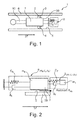
- Fig. 1 shows a cylinder assembly 1 with base system 9 and Tilger 8.
- the cylinder assembly comprises a cylinder 6 and a piston 7 disposed therein, wherein the piston 7 has a sealing element 2 for sealing the relatively movable components piston 7 and cylinder 6 and at least one contact lip 3 with a circumference 4, which is adapted to fit circumferentially slidably in installation on a corresponding sealing surface 5 of the cylinder 6 and thus a Adjust sealing effect.
- the cylinder assembly 1 without absorber 8 represents a base system 9.
- the base system 9 and absorber 8 swing in the same direction 37.
- the piston 7 moves with respect to the sealing surface 5 on the cylinder 6 with a (changing) speed 38.
- the absorber 8 increases the damping of the base system 9 and attenuates an excitation frequency of the base system 9.
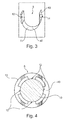
- Fig. 3 shows a first embodiment of a damper 8.
- the damper 8 consists of a sheet metal part 11 (corresponding to a spring arm 40) having a first end 12 and a second end 13.
- the damper 8 is about the first end 12 z. B. attached to an end face 37 of the piston 7.
- an additional mass 14 is arranged.
- Sheet metal part 11 and additional mass 14 form a spring-damper system and thus a damper. 8
- Fig. 4 shows a second embodiment of an annular damper 8.
- the damper 8 is arranged on a plurality of first ends 12 directly to the piston 7 or (as shown here) on the piston rod 10.
- the absorber 8 extends completely around the piston rod 10 / the piston 7.
- the outer peripheral surface of the annular Tilgers 8 forms the second end 13.
- First ends 12 and second end 13 form a spring-damper system and thus a damper. 8
- Fig. 5 shows a hydraulic or pneumatic return system 17, wherein in a master cylinder assembly 15, a master piston 19 in a master cylinder 20 via a clutch pedal 33 is actuated.
- the master piston 19 is opposite to the master cylinder 20 by means of a sealing element 2, as for example in Fig. 1 is shown, sealed, and thus a fluid 23 in the master cylinder 20 by the master piston 19 can be influenced.
- the connecting line 35 the fluid 23 is pressed upon actuation of the clutch pedal 33 in the slave cylinder 22 of a slave cylinder assembly 16 and by another sealing element 2, as shown for example in FIG Fig. 1 is shown, the effect of the flowing fluid 23 is transmitted to the slave piston 21.
- the friction clutch 18 has an axis of rotation 24 about which the elements of the friction clutch 18 rotate.
- a motor vehicle 28 is shown with a drive unit 29, which is arranged with its motor axis 32 transversely to the longitudinal axis 31 in front of the driver's cab 30.
- the drive unit 29 is shown here as an internal combustion engine, which is connected via an output shaft 25 by means of a friction clutch 18, which has a rotation axis 24 in alignment with the motor axis 32, with a drive train 26 shown purely schematically here.
Landscapes
- Engineering & Computer Science (AREA)
- General Engineering & Computer Science (AREA)
- Mechanical Engineering (AREA)
- Fluid-Damping Devices (AREA)
- Hydraulic Clutches, Magnetic Clutches, Fluid Clutches, And Fluid Joints (AREA)
Abstract
Description
- Die Erfindung betrifft eine Zylinderanordnung mit einem Tilger, zumindest umfassend einen Zylinder und einen darin angeordneten Kolben, wobei der Kolben mindestens ein Dichtelement zum Dichten der relativ zueinander verschiebbaren Bauteile Kolben und Zylinder aufweist; und ein hydraulisches oder pneumatisches Rücksystem für eine Reibkupplung, insbesondere für ein Kraftfahrzeug.
- Im Stand der Technik sind verschiedene Dichtelemente bekannt, die zum Dichten in einem hydraulischen System geeignet sind. Dabei kann jedoch aufgrund der Federkraft der Kontaktlippe und dem Reibkontakt mit der korrespondierenden Dichtfläche ein sogenannter Stick-Slip-Effekt auftreten, das heißt die Kontaktlippe hebt aufgrund der Reibung und der Vorspannung ab und senkt sich wieder und erzeugt so ein hörbares Geräusch, zum Beispiel ein Rattern oder Quietschen. Dieser Effekt ist bei manchen Werkstoffen, wie zum Beispiel silikonbasierten Dichtungen, vermindert. Allerdings sind solche Werkstoffe nicht mit allen gängigen Medien, zum Beispiel Bremsflüssigkeiten, kompatibel. Dichtungen aus EPDM (Ethylen-Propylen-Dien-Kautschuk) zum Beispiel sind über ein großes Feld von Medien einsetzbar. Dieser Werkstoff neigt jedoch zum Quietschen aufgrund eines ausgeprägten Stick-Slip-Effekts. Die nachfolgende Erfindung ist mit jeglichem Dichtwerkstoff ausführbar.
- Hiervon ausgehend liegt der vorliegenden Erfindung die Aufgabe zugrunde, die aus dem Stand der Technik bekannten Nachteile zumindest teilweise zu überwinden und die hörbaren Geräusche zu eliminieren oder zumindest zu dämpfen. Die Aufgabe wird durch die Merkmale des unabhängigen Patentanspruchs 1 gelöst. Vorteilhafte Weiterbildungen sind Gegenstand der abhängigen Patentansprüche.
- Die Erfindung betrifft eine Zylinderanordnung mit einem Tilger, zumindest umfassend einen Zylinder und einen darin angeordneten Kolben, wobei der Kolben mindestens ein Dichtelement zum Dichten der relativ zueinander verschiebbaren Bauteile Kolben und Zylinder aufweist und zumindest eine Kontaktlippe mit einem Umfang umfasst, die dazu eingerichtet ist, im Einbau verschiebbar an einer korrespondierenden Dichtfläche des Zylinders umfänglich anzuliegen und somit eine Dichtwirkung einzustellen; wobei die Zylinderanordnung ohne Tilger ein Basissystem darstellt und durch die folgenden Parameter charakterisiert wird:
- mB (Masse des Basissystems),
- cB (Steifigkeit des Basissystems),
- dB (Dämpfung des Basissystems), und
- ωB (Eigenfrequenz des Basissystems), wobei ωB = √(cB/mB);
- mT (Masse des Tilgers),
- cT (Steifigkeit des Tilgers),
- dT (Dämpfung des Tilgers) und
- ωT (Eigenfrequenz des Tilgers), wobei ωT = √(cT/mT); und der Tilger folgende Bedingungen erfüllt:
-

und -

- Im Rahmen der vorliegenden Erfindung wurde herausgefunden, dass die Hauptursache für das Quietschen ein negativer Reibwertgradient (eine Senkung des Reibwertes zwischen Dichtelement und Dichtfläche bei Erhöhung der Geschwindigkeit des Kolbens) ist. Daher wird ein Tilger vorgeschlagen, der den Effekt des negativen Reibwertgradienten neutralisieren soll. Der Tilger soll insbesondere die Dämpfung des Basissystems erhöhen.
- Im Rahmen der Erfindung wurde zudem herausgefunden, dass die Eigenfrequenz des Tilgers nicht mit der Eigenfrequenz des Basissystems übereinstimmen sollte, da die erzeugten Schwingungen des Basissystems sehr stark von der Geschwindigkeit des Kolbens abhängen.
- Für die Berechnung der einzelnen Parameter werden die folgenden Einheiten verwendet:
- mB (Masse des Basissystems): in [kg]
- cB (Steifigkeit des Basissystems): in [Newton/m]
- dB (Dämpfung des Basissystems): in [Newton*s/m]
- ωB (Eigenfrequenz des Basissystems): in [Hz]
- mT (Masse des Tilgers): in [kg]
- cT (Steifigkeit des Tilgers): [Newton/m]
- dT (Dämpfung des Tilgers): in [Newton*s/m]
- ωT (Eigenfrequenz des Tilgers): in [Hz]
- Insbesondere wird durch den Tilger die Dämpfung des Basissystems erhöht, also die Dämpfung des Basissystems plus Tilger als die Dämpfung des Basissystems. Dadurch soll die Wirkung des negativen Reibwertgradienten neutralisiert werden. Die dafür erforderliche Erhöhung der Dämpfung ist individuell für jede konkrete Anwendung bestimmbar.
- Die Zylinderanordnung umfasst zum Beispiel ein Dichtelement eines Kolbens, zum Beispiel eines Geberkolbens oder Nehmerkolbens eines hydraulischen oder pneumatischen Rücksystems, die der Abdichtung einer hydraulischen Flüssigkeit oder eines pneumatischen Gases gegenüber der Umgebung dient. Das Dichtelement weist dazu eine Kontaktlippe auf, die auf einer korrespondierenden Dichtfläche aufliegt und relativ zur Dichtfläche eine Bewegung ausführt. Die Kontaktlippe ist dabei derart gegen die Dichtfläche gepresst, dass keine beziehungsweise nur eine vernachlässigbare Menge der hydraulischen Flüssigkeit oder des pneumatischen Gases diese Barriere durchbrechen kann. Die Kontaktlippe muss dabei nicht allein die Kraft auf die Kontaktlippe aufbringen, sondern er kann zudem so eingerichtet sein, dass er durch das Fluid unterstützt wird und die Kontaktlippe zusätzlich gegen die korrespondierende Dichtfläche gepresst wird.
- Bei der hier vorgeschlagenen Zylinderanordnung ist der Tilger insbesondere unmittelbar an einer Kolbenstange oder an dem Kolben angeordnet.
- Bevorzugt ist der Tilger ringförmig und umschließt eine Kolbenstange oder den Kolben und ist unmittelbar an einer Kolbenstange oder an dem Kolben angeordnet.
- Gemäß einer bevorzugten Ausgestaltung umfasst der Tilger ein gebogenes Blechteil, dass an einem ersten Ende an dem Kolben oder an einer Kolbenstange befestigt ist und an einem zweiten Ende, das frei schwingen kann eine Zusatzmasse aufweist.
- Insbesondere ist der Tilger einstückig ausgeführt. Das heißt insbesondere, dass alle Bauteile des Tilgers stoffschlüssig miteinander verbunden sind. Stoffschlüssige Verbindungen werden insbesondere Verbindungen genannt, bei denen die Verbindungspartner durch atomare oder molekulare Kräfte zusammengehalten werden. Sie sind gleichzeitig nicht lösbare Verbindungen, die sich nur durch Zerstörung der Verbindungsmittel trennen lassen.
- Bevorzugt umfasst der Tilger eine Mehrzahl von einzelnen Tilgern, die zusammen insbesondere die für den einzelnen Tilger angeführten Eigenschaften aufweisen.
- Der Tilger besteht insbesondere aus einer Masse und einem Feder-Dämpfer-Element.
- Insbesondere stellt der Tilger einen Oszillator dar, der in einer bestimmten Richtung schwingt. Insbesondere ist die Richtung der Schwingung des Oszillators mit der Richtung der Schwingung des Basissystems gleichgerichtet.
- Der hier vorgeschlagene Tilger weist insbesondere eine Zusatzmasse auf, die an einem Federarm (z. B. das oben angeführte Blechteil) aufgehängt ist und somit ein Schwingungssystem mit einer vorbestimmbaren Eigenfrequenz (Eigenfrequenz des Tilgers) bildet. Dabei ist die Masse der Zusatzmasse und/oder die Federkraft des Federarms entsprechend einer gewünschten Eigenfrequenz einstellbar und bildet so einen Dämpfer. Die Eigenfrequenz wird dabei in vorteilhafter Weise derart eingerichtet, dass eine vorbestimmte Anregungsfrequenz, die das Basissystem und/oder die Kontaktlippe in Schwingungen versetzen und somit einen Stick-Slip-Effekt anregen könnte, gedämpft wird. Damit wird die Anregung der Kontaktlippe vermindert oder sogar eliminiert.
- Gemäß einem weiteren Aspekt der Erfindung wird ein hydraulisches oder pneumatisches Rücksystem für eine Reibkupplung vorgeschlagen, aufweisend zumindest die folgenden Komponenten:
- eine Geberzylinderanordnung mit einem Geberkolben in einem Geberzylinder,
- eine Nehmerzylinderanordnung mit einem Nehmerkolben in einem Nehmerzylinder ,
- Das hydraulische oder pneumatische Rücksystem besteht aus einem Geberkolben, welcher in einem Geberzylinder ein Gebervolumen komprimieren kann und einem entsprechenden Nehmerkolben, welcher in einem Nehmerzylinder infolge einer Volumenerweiterung im Nehmerzylinder bewegt wird. Entgegen der Namensgebung Geberkolben und Nehmerkolben ist auch eine rückläufige Übertragung der Kräfte möglich. Zudem kann eine Übersetzung durch unterschiedliche Kolbenflächen oder sonstige Elemente stattfinden. Zumindest einer der Zylinderanordnungen ist dabei erfindungsgemäß ausgeführt, wobei der Tilger den Effekt des negativen Reibwertgradienten zumindest teilweise neutralisiert. Der Tilger erhöht insbesondere die Dämpfung des Basissystems.
- Weiterhin wird eine Reibkupplung mit einer Rotationsachse zum lösbaren Verbinden einer Abtriebswelle mit einem Antriebsstrang vorgeschlagen, welche zumindest die folgenden Komponenten aufweist:
- zumindest ein Reibpaket, wobei über das Reibpaket im angepressten Zustand ein Drehmoment übertragbar ist;
- ein Rücksystem gemäß der obigen Beschreibung zum Betätigen des Reibpakets mittels des Nehmerkolbens.
- Die Reibkupplung ist dazu eingerichtet, ein Drehmoment lösbar von einer Abtriebswelle auf einen Antriebsstrang und umgekehrt zu übertragen. Dies wird in der Regel über das zumindest eine Reibpaket, wie es oben beschrieben ist, erreicht, welches eine axial verschiebbare, in der Regel mit der Abtriebswelle rotationsfeste, Anpressplatte aufweist, die gegen zumindest eine korrespondierende Reibscheibe pressbar ist und dann ein Drehmoment übertragen kann. Die Kraft wird hierbei durch ein Betätigungssystem erzeugt, welches direkt oder indirekt durch einen Benutzer betätigt wird. Von diesem Betätigungssystem geht die Kraft aus, die zu einer axialen Verpressung des zumindest einen Reibpakets führt. Besonders bevorzugt ist das Betätigungssystem dabei hydraulisch oder pneumatisch eingerichtet, wodurch besonders große Axialkräfte erzeugt werden können und ein Übersetzungsverhältnis leicht einstellbar ist. Hierbei ist der Einsatz einer Zylinderanordnung gemäß der obigen Beschreibung vorteilhaft, weil Geräusche den Fahrer beunruhigen können.
- Weiterhin wird auch ein Kraftfahrzeug vorgeschlagen, welches eine Antriebseinheit mit einer Abtriebswelle, einen Antriebsstrang und eine Reibkupplung gemäß der obigen Beschreibung zum lösbaren Verbinden der Abtriebswelle mit dem Antriebsstrang aufweist.
- Die meisten Kraftfahrzeuge weisen heutzutage einen Frontantrieb auf und ordnen daher bevorzugt die Antriebseinheit, beispielsweise eine Verbrennungskraftmaschine oder einen Elektromotor, vor der Fahrerkabine und quer zur Hauptfahrrichtung an. Der Bauraum ist gerade bei einer solchen Anordnung besonders gering und es ist daher besonders vorteilhaft, eine Reibkupplung kleiner Baugröße zu verwenden.
- Verschärft wird die Bauraumsituation bei Personenkraftwagen der Kleinwagenklasse nach europäischer Klassifizierung. Die verwendeten Aggregate in einem Personenkraftwagen der Kleinwagenklasse sind gegenüber Personenkraftwagen größerer Wagenklassen nicht wesentlich verkleinert. Dennoch ist der zur Verfügung stehende Bauraum bei Kleinwagen wesentlich kleiner. Die hier Zylinderanordnung erlaubt einen geräuschfreien Betrieb eines hydraulischen Ausrückers. Dies ist für den Fahrer besonders angenehm und für Kleinwagen setzt sich die hydraulische Betätigung aufgrund zunehmender Bauteilmengen durch.
- Personenkraftwagen werden einer Fahrzeugklasse nach beispielsweise Größe, Preis, Gewicht, Leistung eingeordnet, wobei diese Definition einem steten Wandel nach den Bedürfnissen des Marktes unterliegt. Im US-Markt werden Fahrzeuge der Klasse Kleinwagen und Kleinstwagen nach europäischer Klassifizierung der Klasse der Subcompact Car zugeordnet und im Britischen Markt entsprechen sie der Klasse Supermini beispielsweise der Klasse City Car. Beispiele der Kleinstwagenklasse sind ein Volkswagen Fox oder ein Renault Twingo. Beispiele der Kleinwagenklasse sind ein Alfa Romeo Mito, Volkswagen Polo, Ford Fiesta oder Renault Clio.
- Die in den Patentansprüchen einzeln aufgeführten Merkmale sind in beliebiger, technologisch sinnvoller Weise miteinander kombinierbar und können durch erläuternde Sachverhalte aus der Beschreibung und Details aus den Figuren ergänzt werden, wobei weitere Ausführungsvarianten der Erfindung aufgezeigt werden.
- Die Erfindung sowie das technische Umfeld werden nachfolgend anhand der Figuren näher erläutert. Die Figuren zeigen besonders bevorzugte Ausführungsbeispiele, auf die die Erfindung jedoch nicht beschränkt ist. Insbesondere ist darauf hinzuweisen, dass die Figuren und insbesondere die dargestellten Größenverhältnisse nur schematisch sind. Gleiche Bezugszeichen bezeichnen gleiche Gegenstände. Es zeigen:
- Fig. 1:
- eine Zylinderanordnung mit Basissystem und Tilger;
- Fig. 2:
- eine schematische Darstellung der Zylinderanordnung gemäß
Fig. 1 ; - Fig. 3:
- eine erste Ausführungsvariante eines Tilgers;
- Fig. 4:
- eine zweite Ausführungsvariante eines Tilgers;
- Fig. 5:
- ein Rücksystem mit Reibkupplung;
- Fig. 6:
- ein Kraftfahrzeug.
-
Fig. 1 zeigt eine Zylinderanordnung 1 mit Basissystem 9 und Tilger 8. Die Zylinderanordnung umfasst einen Zylinder 6 und einen darin angeordneten Kolben 7, wobei der Kolben 7 ein Dichtelement 2 zum Dichten der relativ zueinander verschiebbaren Bauteile Kolben 7 und Zylinder 6 aufweist und zumindest eine Kontaktlippe 3 mit einem Umfang 4 umfasst, die dazu eingerichtet ist, im Einbau verschiebbar an einer korrespondierenden Dichtfläche 5 des Zylinders 6 umfänglich anzuliegen und somit eine Dichtwirkung einzustellen. Die Zylinderanordnung 1 ohne Tilger 8 stellt ein Basissystem 9 dar. -
Fig. 2 zeigt eine schematische Darstellung der Zylinderanordnung gemäßFig. 1 mit Basissystem 9 und Tilger 8. Das Basissystem 9 wird durch die folgenden Parameter charakterisiert: - mB (Masse des Basissystems),
- cB (Steifigkeit des Basissystems),
- dB (Dämpfung des Basissystems), und
- ωB (Eigenfrequenz des Basissystems), wobei ωB = √(cB/mB).
- Der Tilger 8 ist an dem Basissystem 9 befestigt und weist folgende Parameter auf:
- mT (Masse des Tilgers),
- cT (Steifigkeit des Tilgers),
- dT (Dämpfung des Tilgers), und
- ωT (Eigenfrequenz des Tilgers), wobei ωT = √(cT/mT).
- Basissystem 9 und Tilger 8 schwingen in derselben Richtung 37. Der Kolben 7 bewegt sich gegenüber der Dichtfläche 5 am Zylinder 6 mit einer (sich verändernden) Geschwindigkeit 38.
- Der Tilger 8 erhöht die Dämpfung des Basissystems 9 und dämpft eine Anregungsfrequenz des Basissystems 9.
-
Fig. 3 zeigt eine erste Ausführungsvariante eines Tilgers 8. Hier besteht der Tilger 8 aus einem Blechteil 11 (entspricht einem Federarm 40) mit einem ersten Ende 12 und einem zweiten Ende 13. Der Tilger 8 ist über das erste Ende 12 z. B. an einer Stirnfläche 37 des Kolbens 7 befestigt. An dem zweiten Ende 13 ist eine Zusatzmasse 14 angeordnet. Blechteil 11 und Zusatzmasse 14 bilden ein Feder-Dämpfer-System und damit einen Tilger 8. -
Fig. 4 zeigt eine zweite Ausführungsvariante eines ringförmigen Tilgers 8. Der Tilger 8 ist über eine Mehrzahl von ersten Enden 12 unmittelbar an dem Kolben 7 oder (wie hier gezeigt) an der Kolbenstange 10 angeordnet. Der Tilger 8 erstreckt sich vollumfänglich um die Kolbenstange 10/ den Kolben 7. Die äußere Umfangsfläche des ringförmigen Tilgers 8 bildet das zweite Ende 13. Erste Enden 12 und zweites Ende 13 bilden ein Feder-Dämpfer-System und damit einen Tilger 8. -
Fig. 5 zeigt ein hydraulisches oder pneumatisches Rücksystem 17, wobei in einer Geberzylinderanordnung 15 ein Geberkolben 19 in einem Geberzylinder 20 über ein Kupplungspedal 33 betätigbar ist. Der Geberkolben 19 ist gegenüber dem Geberzylinder 20 mittels eines Dichtelements 2, wie es zum Beispiel inFig. 1 gezeigt ist, abgedichtet und somit ist ein Fluid 23 in dem Geberzylinder 20 durch den Geberkolben 19 beeinflussbar. Über die Verbindungsleitung 35 wird das Fluid 23 bei einem Betätigen des Kupplungspedals 33 in den Nehmerzylinder 22 einer Nehmerzylinderanordnung 16 gedrückt und durch ein weiteres Dichtelement 2, wie es zum Beispiel inFig. 1 gezeigt ist, wird die Wirkung des strömenden Fluids 23 auf den Nehmerkolben 21 übertragen. Dieser wiederum betätigt eine Tellerfeder 36, die somit das Reibpaket 27 einer Reibkupplung 18 voneinander ausrückt, so dass ein an einer Abtriebswelle 25 anliegendes Drehmoment nicht weiter auf die Getriebewelle 34 übertragen wird. Die Reibkupplung 18 weist eine Rotationsachse 24 auf, um die die Elemente der Reibkupplung 18 rotieren. - In
Fig. 6 ist ein Kraftfahrzeug 28 mit einer Antriebseinheit 29 gezeigt, welche mit ihrer Motorachse 32 quer zur Längsachse 31 vor der Fahrerkabine 30 angeordnet ist. Die Antriebseinheit 29 ist hier als Verbrennungskraftmaschine dargestellt, welche über eine Abtriebswelle 25 mittels einer Reibkupplung 18, die eine Rotationsachse 24 in Flucht mit der Motorachse 32 aufweist, mit einem hier rein schematisch dargestellten Antriebsstrang 26 verbunden ist. - Mit der hier vorgeschlagenen Zylinderanordnung 1 mit zumindest einem Tilger 8 wird der Stick-Slip-Effekt verringert und die Anregung der Kontaktlippe 3 gedämpft, so dass Geräusche zumindest weitgehend eliminiert werden.
-
- 1
- Zylinderanordnung
- 2
- Dichtelement
- 3
- Kontaktlippe
- 4
- Umfang
- 5
- Dichtfläche
- 6
- Zylinder
- 7
- Kolben
- 8
- Tilger
- 9
- Basissystem
- 10
- Kolbenstange
- 11
- Blechteil
- 12
- erstes Ende
- 13
- zweites Ende
- 14
- Zusatzmasse
- 15
- Geberzylinderanordnung
- 16
- Nehmerzylinderanordnung
- 17
- hydraulisches oder pneumatisches Rücksystem
- 18
- Reibkupplung
- 19
- Geberkolben
- 20
- Geberzylinder
- 21
- Nehmerkolben
- 22
- Nehmerzylinder
- 23
- Fluid
- 24
- Rotationsachse
- 25
- Abtriebswelle
- 26
- Antriebsstrang
- 27
- Reibpaket
- 28
- Kraftfahrzeug
- 29
- Antriebseinheit
- 30
- Fahrerkabine
- 31
- Längsachse
- 32
- Motorachse
- 33
- Kupplungspedal
- 34
- Getriebewelle
- 35
- Verbindungsleitung
- 36
- Tellerfeder
- 37
- Richtung
- 38
- Geschwindigkeit
- 39
- Stirnfläche
- 40
- Federarm
- mB
- Masse des Basissystems
- cB
- Steifigkeit des Basissystems
- dB
- Dämpfung des Basissystems
- ωB
- Eigenfrequenz des Basissystems
- mT
- Masse des Tilgers
- cT
- Steifigkeit des Tilgers
- dT
- Dämpfung des Tilgers
- ωT
- Eigenfrequenz des Tilgers
Claims (7)
- Zylinderanordnung (1) mit einem Tilger (8), zumindest umfassend einen Zylinder (6) und einen darin angeordneten Kolben (7), wobei der Kolben (7) mindestens ein Dichtelement (2) zum Dichten der relativ zueinander verschiebbaren Bauteile Kolben (7) und Zylinder (6) aufweist und zumindest eine Kontaktlippe (3) mit einem Umfang (4) umfasst, die dazu eingerichtet ist, im Einbau verschiebbar an einer korrespondierenden Dichtfläche (5) des Zylinders (6) umfänglich anzuliegen und somit eine Dichtwirkung einzustellen; wobei die Zylinderanordnung (1) ohne Tilger (8) ein Basissystem (9) darstellt und durch die folgenden Parameter charakterisiert wird:• mB (Masse des Basissystems),• cB (Steifigkeit des Basissystems),• dB (Dämpfung des Basissystems), und• ωB (Eigenfrequenz des Basissystems), wobei ωB = √(cB/mB)dadurch gekennzeichnet, dass der Tilger (8) an dem Basissystem (9) befestigt ist und folgende Parameter aufweist:• mT (Masse des Tilgers),• cT (Steifigkeit des Tilgers),• dT (Dämpfung des Tilgers), und• ωT (Eigenfrequenz des Tilgers), wobei ωT = √(cT/mT); und
der Tilger (8) folgende Bedingungen erfüllt:•
und•
wobei der Tilger (8) die Dämpfung des Basissystems (9) erhöht und eine Anregungsfrequenz des Basissystems (9) dämpft. - Zylinderanordnung (1) nach Anspruch 1, wobei der Tilger (8) unmittelbar an einer Kolbenstange (10) oder an dem Kolben (7) angeordnet ist.
- Zylinderanordnung (1) nach einem der vorhergehenden Ansprüche, wobei der Tilger (8) ringförmig ist und eine Kolbenstange (10) oder den Kolben (7) umschließt und unmittelbar an einer Kolbenstange (10) oder an dem Kolben (7) angeordnet ist.
- Zylinderanordnung (1) nach einem der Ansprüche 1 und 2, wobei der Tilger (8) ein gebogenes Blechteil (11) umfasst, dass an einem ersten Ende (12) an dem Kolben (7) oder an einer Kolbenstange (10) befestigt ist und an einem zweiten Ende (13), das frei schwingen kann eine Zusatzmasse (14) aufweist.
- Zylinderanordnung (1) nach einem der vorhergehenden Ansprüche, wobei der Tilger (8) einstückig ausgeführt ist.
- Zylinderanordnung (1) nach einem der vorhergehenden Ansprüche, wobei der Tilger (8) eine Mehrzahl von einzelnen Tilgern (8) umfasst.
- Hydraulisches oder pneumatisches Rücksystem (17) für eine Reibkupplung (18), aufweisend zumindest die folgenden Komponenten:• eine Geberzylinderanordnung (15) mit einem Geberkolben (19) in einem Geberzylinder (20),• eine Nehmerzylinderanordnung (16) mit einem Nehmerkolben (21) in einem Nehmerzylinder (22),wobei die Geberzylinderanordnung (15) und die Nehmerzylinderanordnung (16) strömungstechnisch miteinander kommunizieren, sodass eine Bewegung des Geberkolbens (19) in eine Bewegung des Nehmerkolbens (21) umsetzbar ist, wobei zumindest einer der Zylinderanordnungen (15, 16) zumindest eine Zylinderanordnung (1) nach einem der vorhergehenden Ansprüche umfasst, wobei mittels des Dichtelements (2) der Kolben (7, 19, 21) gegenüber dem zugehörigen Zylinder (6, 20, 22) derart abdichtbar ist, dass ein Überströmen eines Fluids (23) im zugehörigen Zylinder (6, 20,22) unterbindbar ist.
Applications Claiming Priority (1)
| Application Number | Priority Date | Filing Date | Title |
|---|---|---|---|
| DE102014214207.5A DE102014214207A1 (de) | 2014-07-22 | 2014-07-22 | Tilger zur Beseitigung der reiberregten Schwingungen im Ausrücksystem |
Publications (3)
| Publication Number | Publication Date |
|---|---|
| EP2977638A2 true EP2977638A2 (de) | 2016-01-27 |
| EP2977638A3 EP2977638A3 (de) | 2016-02-17 |
| EP2977638B1 EP2977638B1 (de) | 2017-05-31 |
Family
ID=53610761
Family Applications (1)
| Application Number | Title | Priority Date | Filing Date |
|---|---|---|---|
| EP15173657.6A Not-in-force EP2977638B1 (de) | 2014-07-22 | 2015-06-24 | Tilger zur beseitigung der reiberregten schwingungen im ausrücksystem |
Country Status (2)
| Country | Link |
|---|---|
| EP (1) | EP2977638B1 (de) |
| DE (1) | DE102014214207A1 (de) |
Cited By (1)
| Publication number | Priority date | Publication date | Assignee | Title |
|---|---|---|---|---|
| WO2017140306A1 (de) * | 2016-02-18 | 2017-08-24 | Schaeffler Technologies AG & Co. KG | Kupplungsgeberzylinder mit dämpfer |
Families Citing this family (2)
| Publication number | Priority date | Publication date | Assignee | Title |
|---|---|---|---|---|
| DE102016210192A1 (de) | 2016-06-09 | 2017-12-14 | Schaeffler Technologies AG & Co. KG | Hydraulisches System mit verbesserter Dämpfung |
| DE102017112398A1 (de) | 2017-06-06 | 2018-12-06 | Schaeffler Technologies AG & Co. KG | Reibeinrichtung mit zumindest einem auf eine Modenkopplung abgestimmten Tilger |
Family Cites Families (3)
| Publication number | Priority date | Publication date | Assignee | Title |
|---|---|---|---|---|
| SU1310544A1 (ru) * | 1985-07-19 | 1987-05-15 | А.В.Андрейчиков | Гаситель колебаний |
| DE102007049444A1 (de) * | 2007-10-16 | 2009-04-30 | Zf Friedrichshafen Ag | Schwingungsdämpfer |
| WO2014034034A1 (ja) * | 2012-08-29 | 2014-03-06 | マツダ株式会社 | エンジンのピストン構造 |
-
2014
- 2014-07-22 DE DE102014214207.5A patent/DE102014214207A1/de not_active Withdrawn
-
2015
- 2015-06-24 EP EP15173657.6A patent/EP2977638B1/de not_active Not-in-force
Non-Patent Citations (1)
| Title |
|---|
| None |
Cited By (1)
| Publication number | Priority date | Publication date | Assignee | Title |
|---|---|---|---|---|
| WO2017140306A1 (de) * | 2016-02-18 | 2017-08-24 | Schaeffler Technologies AG & Co. KG | Kupplungsgeberzylinder mit dämpfer |
Also Published As
| Publication number | Publication date |
|---|---|
| DE102014214207A1 (de) | 2016-01-28 |
| EP2977638A3 (de) | 2016-02-17 |
| EP2977638B1 (de) | 2017-05-31 |
Similar Documents
| Publication | Publication Date | Title |
|---|---|---|
| DE19746281B4 (de) | Reibungskupplung | |
| EP2326852B1 (de) | Antriebstrang mit einer doppelkupplung | |
| WO2007041990A1 (de) | Nehmerzylinder mit axial spielbehaftetem ringkolben | |
| EP2977638B1 (de) | Tilger zur beseitigung der reiberregten schwingungen im ausrücksystem | |
| DE19622707B4 (de) | Betätigungsvorrichtung | |
| DE102013214089A1 (de) | Schwingungsdämpfer, insbesondere für ein Kraftfahrzeug, sowie entsprechende Reibkupplung und entsprechendes Kraftfahrzeug | |
| DE102019101164A1 (de) | Drehschwingungsdämpfer | |
| DE102008017679A1 (de) | Kopplungseinrichtung bzw. Antriebsstrang für Fahrzeuge mit einer Kopplungseinrichtung | |
| EP2843252A2 (de) | Stützvorrichtung für eine Tellerfeder einer Reibkupplung mit einer Rotationsachse | |
| DE102019101113A1 (de) | Rutschkupplung | |
| WO2014094765A1 (de) | Schwingungsisolationseinrichtung für eine nasse doppelkupplung mit schwingungsisolationsvorrichtung im nassraum | |
| WO2015135539A1 (de) | Dichtlippe für ein dichtelement zum dichten zweier relativ zueinander verschiebbarer teile | |
| WO2007082500A1 (de) | Drehmomentübertragungseinrichtung | |
| DE102009016225A1 (de) | Kolben-Zylinder-Aggregat | |
| DE102019130586A1 (de) | Hybrider Antriebsstrang mit Trennkupplungsmodul und Elektromotor in P3-Konfiguration | |
| DE102017127215A1 (de) | Kupplungsscheibe mit einer Rotationsachse | |
| EP2368058B1 (de) | Anlasserscheibe mit rutschkupplung | |
| DE102016223394A1 (de) | Zweimassenschwungrad mit sekundärseitiger Zusatzmasse | |
| DE102021107964A1 (de) | Drehmomentübertragungseinrichtung | |
| DE102014001660A1 (de) | Stützlager zur Lagerung eines Dämpfer- und/oder Federbeins | |
| DE102014211758A1 (de) | Betätigungssystem für eine Reibkupplung | |
| DE102009014965A1 (de) | Hydrolager | |
| WO2015144154A2 (de) | Spindeltrieb für eine weggesteuerte nachstelleinrichtung | |
| DE102013224475A1 (de) | Trägerelement für eine Druckkammer einer Reibkupplung | |
| WO2015124150A1 (de) | Dichtlippe für ein dichtelement zum dichten zweier relativ zueinander verschiebbarer teile |
Legal Events
| Date | Code | Title | Description |
|---|---|---|---|
| PUAL | Search report despatched |
Free format text: ORIGINAL CODE: 0009013 |
|
| PUAI | Public reference made under article 153(3) epc to a published international application that has entered the european phase |
Free format text: ORIGINAL CODE: 0009012 |
|
| AK | Designated contracting states |
Kind code of ref document: A2 Designated state(s): AL AT BE BG CH CY CZ DE DK EE ES FI FR GB GR HR HU IE IS IT LI LT LU LV MC MK MT NL NO PL PT RO RS SE SI SK SM TR |
|
| AX | Request for extension of the european patent |
Extension state: BA ME |
|
| AK | Designated contracting states |
Kind code of ref document: A3 Designated state(s): AL AT BE BG CH CY CZ DE DK EE ES FI FR GB GR HR HU IE IS IT LI LT LU LV MC MK MT NL NO PL PT RO RS SE SI SK SM TR |
|
| AX | Request for extension of the european patent |
Extension state: BA ME |
|
| RIC1 | Information provided on ipc code assigned before grant |
Ipc: F16F 7/104 20060101AFI20160113BHEP |
|
| 17P | Request for examination filed |
Effective date: 20160817 |
|
| RBV | Designated contracting states (corrected) |
Designated state(s): AL AT BE BG CH CY CZ DE DK EE ES FI FR GB GR HR HU IE IS IT LI LT LU LV MC MK MT NL NO PL PT RO RS SE SI SK SM TR |
|
| REG | Reference to a national code |
Ref country code: DE Ref legal event code: R079 Ref document number: 502015001135 Country of ref document: DE Free format text: PREVIOUS MAIN CLASS: F16F0007104000 Ipc: F16D0025120000 |
|
| GRAJ | Information related to disapproval of communication of intention to grant by the applicant or resumption of examination proceedings by the epo deleted |
Free format text: ORIGINAL CODE: EPIDOSDIGR1 |
|
| RIC1 | Information provided on ipc code assigned before grant |
Ipc: F16D 25/08 20060101ALN20161027BHEP Ipc: F16F 7/104 20060101ALI20161027BHEP Ipc: F16D 25/12 20060101AFI20161027BHEP |
|
| GRAP | Despatch of communication of intention to grant a patent |
Free format text: ORIGINAL CODE: EPIDOSNIGR1 |
|
| INTG | Intention to grant announced |
Effective date: 20161206 |
|
| GRAS | Grant fee paid |
Free format text: ORIGINAL CODE: EPIDOSNIGR3 |
|
| GRAA | (expected) grant |
Free format text: ORIGINAL CODE: 0009210 |
|
| AK | Designated contracting states |
Kind code of ref document: B1 Designated state(s): AL AT BE BG CH CY CZ DE DK EE ES FI FR GB GR HR HU IE IS IT LI LT LU LV MC MK MT NL NO PL PT RO RS SE SI SK SM TR |
|
| REG | Reference to a national code |
Ref country code: CH Ref legal event code: EP Ref country code: GB Ref legal event code: FG4D Free format text: NOT ENGLISH |
|
| REG | Reference to a national code |
Ref country code: AT Ref legal event code: REF Ref document number: 897777 Country of ref document: AT Kind code of ref document: T Effective date: 20170615 |
|
| REG | Reference to a national code |
Ref country code: IE Ref legal event code: FG4D Free format text: LANGUAGE OF EP DOCUMENT: GERMAN |
|
| REG | Reference to a national code |
Ref country code: FR Ref legal event code: PLFP Year of fee payment: 3 |
|
| REG | Reference to a national code |
Ref country code: DE Ref legal event code: R096 Ref document number: 502015001135 Country of ref document: DE |
|
| REG | Reference to a national code |
Ref country code: NL Ref legal event code: MP Effective date: 20170531 |
|
| REG | Reference to a national code |
Ref country code: LT Ref legal event code: MG4D |
|
| PG25 | Lapsed in a contracting state [announced via postgrant information from national office to epo] |
Ref country code: LT Free format text: LAPSE BECAUSE OF FAILURE TO SUBMIT A TRANSLATION OF THE DESCRIPTION OR TO PAY THE FEE WITHIN THE PRESCRIBED TIME-LIMIT Effective date: 20170531 Ref country code: ES Free format text: LAPSE BECAUSE OF FAILURE TO SUBMIT A TRANSLATION OF THE DESCRIPTION OR TO PAY THE FEE WITHIN THE PRESCRIBED TIME-LIMIT Effective date: 20170531 Ref country code: NO Free format text: LAPSE BECAUSE OF FAILURE TO SUBMIT A TRANSLATION OF THE DESCRIPTION OR TO PAY THE FEE WITHIN THE PRESCRIBED TIME-LIMIT Effective date: 20170831 Ref country code: FI Free format text: LAPSE BECAUSE OF FAILURE TO SUBMIT A TRANSLATION OF THE DESCRIPTION OR TO PAY THE FEE WITHIN THE PRESCRIBED TIME-LIMIT Effective date: 20170531 Ref country code: GR Free format text: LAPSE BECAUSE OF FAILURE TO SUBMIT A TRANSLATION OF THE DESCRIPTION OR TO PAY THE FEE WITHIN THE PRESCRIBED TIME-LIMIT Effective date: 20170901 Ref country code: HR Free format text: LAPSE BECAUSE OF FAILURE TO SUBMIT A TRANSLATION OF THE DESCRIPTION OR TO PAY THE FEE WITHIN THE PRESCRIBED TIME-LIMIT Effective date: 20170531 |
|
| PG25 | Lapsed in a contracting state [announced via postgrant information from national office to epo] |
Ref country code: BG Free format text: LAPSE BECAUSE OF FAILURE TO SUBMIT A TRANSLATION OF THE DESCRIPTION OR TO PAY THE FEE WITHIN THE PRESCRIBED TIME-LIMIT Effective date: 20170831 Ref country code: RS Free format text: LAPSE BECAUSE OF FAILURE TO SUBMIT A TRANSLATION OF THE DESCRIPTION OR TO PAY THE FEE WITHIN THE PRESCRIBED TIME-LIMIT Effective date: 20170531 Ref country code: LV Free format text: LAPSE BECAUSE OF FAILURE TO SUBMIT A TRANSLATION OF THE DESCRIPTION OR TO PAY THE FEE WITHIN THE PRESCRIBED TIME-LIMIT Effective date: 20170531 Ref country code: NL Free format text: LAPSE BECAUSE OF FAILURE TO SUBMIT A TRANSLATION OF THE DESCRIPTION OR TO PAY THE FEE WITHIN THE PRESCRIBED TIME-LIMIT Effective date: 20170531 Ref country code: IS Free format text: LAPSE BECAUSE OF FAILURE TO SUBMIT A TRANSLATION OF THE DESCRIPTION OR TO PAY THE FEE WITHIN THE PRESCRIBED TIME-LIMIT Effective date: 20170930 Ref country code: SE Free format text: LAPSE BECAUSE OF FAILURE TO SUBMIT A TRANSLATION OF THE DESCRIPTION OR TO PAY THE FEE WITHIN THE PRESCRIBED TIME-LIMIT Effective date: 20170531 |
|
| PG25 | Lapsed in a contracting state [announced via postgrant information from national office to epo] |
Ref country code: CZ Free format text: LAPSE BECAUSE OF FAILURE TO SUBMIT A TRANSLATION OF THE DESCRIPTION OR TO PAY THE FEE WITHIN THE PRESCRIBED TIME-LIMIT Effective date: 20170531 Ref country code: EE Free format text: LAPSE BECAUSE OF FAILURE TO SUBMIT A TRANSLATION OF THE DESCRIPTION OR TO PAY THE FEE WITHIN THE PRESCRIBED TIME-LIMIT Effective date: 20170531 Ref country code: SK Free format text: LAPSE BECAUSE OF FAILURE TO SUBMIT A TRANSLATION OF THE DESCRIPTION OR TO PAY THE FEE WITHIN THE PRESCRIBED TIME-LIMIT Effective date: 20170531 Ref country code: DK Free format text: LAPSE BECAUSE OF FAILURE TO SUBMIT A TRANSLATION OF THE DESCRIPTION OR TO PAY THE FEE WITHIN THE PRESCRIBED TIME-LIMIT Effective date: 20170531 Ref country code: RO Free format text: LAPSE BECAUSE OF FAILURE TO SUBMIT A TRANSLATION OF THE DESCRIPTION OR TO PAY THE FEE WITHIN THE PRESCRIBED TIME-LIMIT Effective date: 20170531 |
|
| PG25 | Lapsed in a contracting state [announced via postgrant information from national office to epo] |
Ref country code: SM Free format text: LAPSE BECAUSE OF FAILURE TO SUBMIT A TRANSLATION OF THE DESCRIPTION OR TO PAY THE FEE WITHIN THE PRESCRIBED TIME-LIMIT Effective date: 20170531 Ref country code: PL Free format text: LAPSE BECAUSE OF FAILURE TO SUBMIT A TRANSLATION OF THE DESCRIPTION OR TO PAY THE FEE WITHIN THE PRESCRIBED TIME-LIMIT Effective date: 20170531 Ref country code: IT Free format text: LAPSE BECAUSE OF FAILURE TO SUBMIT A TRANSLATION OF THE DESCRIPTION OR TO PAY THE FEE WITHIN THE PRESCRIBED TIME-LIMIT Effective date: 20170531 |
|
| REG | Reference to a national code |
Ref country code: DE Ref legal event code: R097 Ref document number: 502015001135 Country of ref document: DE |
|
| REG | Reference to a national code |
Ref country code: IE Ref legal event code: MM4A |
|
| PLBE | No opposition filed within time limit |
Free format text: ORIGINAL CODE: 0009261 |
|
| STAA | Information on the status of an ep patent application or granted ep patent |
Free format text: STATUS: NO OPPOSITION FILED WITHIN TIME LIMIT |
|
| PG25 | Lapsed in a contracting state [announced via postgrant information from national office to epo] |
Ref country code: LU Free format text: LAPSE BECAUSE OF NON-PAYMENT OF DUE FEES Effective date: 20170624 Ref country code: IE Free format text: LAPSE BECAUSE OF NON-PAYMENT OF DUE FEES Effective date: 20170624 |
|
| REG | Reference to a national code |
Ref country code: BE Ref legal event code: MM Effective date: 20170630 |
|
| 26N | No opposition filed |
Effective date: 20180301 |
|
| PG25 | Lapsed in a contracting state [announced via postgrant information from national office to epo] |
Ref country code: SI Free format text: LAPSE BECAUSE OF FAILURE TO SUBMIT A TRANSLATION OF THE DESCRIPTION OR TO PAY THE FEE WITHIN THE PRESCRIBED TIME-LIMIT Effective date: 20170531 |
|
| REG | Reference to a national code |
Ref country code: FR Ref legal event code: PLFP Year of fee payment: 4 |
|
| PG25 | Lapsed in a contracting state [announced via postgrant information from national office to epo] |
Ref country code: BE Free format text: LAPSE BECAUSE OF NON-PAYMENT OF DUE FEES Effective date: 20170630 |
|
| PG25 | Lapsed in a contracting state [announced via postgrant information from national office to epo] |
Ref country code: MT Free format text: LAPSE BECAUSE OF FAILURE TO SUBMIT A TRANSLATION OF THE DESCRIPTION OR TO PAY THE FEE WITHIN THE PRESCRIBED TIME-LIMIT Effective date: 20170531 |
|
| REG | Reference to a national code |
Ref country code: CH Ref legal event code: PL |
|
| PG25 | Lapsed in a contracting state [announced via postgrant information from national office to epo] |
Ref country code: LI Free format text: LAPSE BECAUSE OF NON-PAYMENT OF DUE FEES Effective date: 20180630 Ref country code: CH Free format text: LAPSE BECAUSE OF NON-PAYMENT OF DUE FEES Effective date: 20180630 |
|
| PG25 | Lapsed in a contracting state [announced via postgrant information from national office to epo] |
Ref country code: MC Free format text: LAPSE BECAUSE OF FAILURE TO SUBMIT A TRANSLATION OF THE DESCRIPTION OR TO PAY THE FEE WITHIN THE PRESCRIBED TIME-LIMIT Effective date: 20170531 Ref country code: HU Free format text: LAPSE BECAUSE OF FAILURE TO SUBMIT A TRANSLATION OF THE DESCRIPTION OR TO PAY THE FEE WITHIN THE PRESCRIBED TIME-LIMIT; INVALID AB INITIO Effective date: 20150624 |
|
| PG25 | Lapsed in a contracting state [announced via postgrant information from national office to epo] |
Ref country code: CY Free format text: LAPSE BECAUSE OF FAILURE TO SUBMIT A TRANSLATION OF THE DESCRIPTION OR TO PAY THE FEE WITHIN THE PRESCRIBED TIME-LIMIT Effective date: 20170531 |
|
| PG25 | Lapsed in a contracting state [announced via postgrant information from national office to epo] |
Ref country code: MK Free format text: LAPSE BECAUSE OF FAILURE TO SUBMIT A TRANSLATION OF THE DESCRIPTION OR TO PAY THE FEE WITHIN THE PRESCRIBED TIME-LIMIT Effective date: 20170531 |
|
| GBPC | Gb: european patent ceased through non-payment of renewal fee |
Effective date: 20190624 |
|
| PG25 | Lapsed in a contracting state [announced via postgrant information from national office to epo] |
Ref country code: TR Free format text: LAPSE BECAUSE OF FAILURE TO SUBMIT A TRANSLATION OF THE DESCRIPTION OR TO PAY THE FEE WITHIN THE PRESCRIBED TIME-LIMIT Effective date: 20170531 |
|
| PG25 | Lapsed in a contracting state [announced via postgrant information from national office to epo] |
Ref country code: GB Free format text: LAPSE BECAUSE OF NON-PAYMENT OF DUE FEES Effective date: 20190624 |
|
| PG25 | Lapsed in a contracting state [announced via postgrant information from national office to epo] |
Ref country code: PT Free format text: LAPSE BECAUSE OF FAILURE TO SUBMIT A TRANSLATION OF THE DESCRIPTION OR TO PAY THE FEE WITHIN THE PRESCRIBED TIME-LIMIT Effective date: 20170531 |
|
| PG25 | Lapsed in a contracting state [announced via postgrant information from national office to epo] |
Ref country code: AL Free format text: LAPSE BECAUSE OF FAILURE TO SUBMIT A TRANSLATION OF THE DESCRIPTION OR TO PAY THE FEE WITHIN THE PRESCRIBED TIME-LIMIT Effective date: 20170531 |
|
| REG | Reference to a national code |
Ref country code: AT Ref legal event code: MM01 Ref document number: 897777 Country of ref document: AT Kind code of ref document: T Effective date: 20200624 |
|
| PG25 | Lapsed in a contracting state [announced via postgrant information from national office to epo] |
Ref country code: AT Free format text: LAPSE BECAUSE OF NON-PAYMENT OF DUE FEES Effective date: 20200624 |
|
| P01 | Opt-out of the competence of the unified patent court (upc) registered |
Effective date: 20230523 |
|
| PGFP | Annual fee paid to national office [announced via postgrant information from national office to epo] |
Ref country code: FR Payment date: 20230628 Year of fee payment: 9 |
|
| PGFP | Annual fee paid to national office [announced via postgrant information from national office to epo] |
Ref country code: DE Payment date: 20230821 Year of fee payment: 9 |
|
| REG | Reference to a national code |
Ref country code: DE Ref legal event code: R119 Ref document number: 502015001135 Country of ref document: DE |
|
| PG25 | Lapsed in a contracting state [announced via postgrant information from national office to epo] |
Ref country code: DE Free format text: LAPSE BECAUSE OF NON-PAYMENT OF DUE FEES Effective date: 20250101 |
|
| PG25 | Lapsed in a contracting state [announced via postgrant information from national office to epo] |
Ref country code: FR Free format text: LAPSE BECAUSE OF NON-PAYMENT OF DUE FEES Effective date: 20240630 |