EP2977493B1 - Spinnmaschine und spinnverfahren - Google Patents
Spinnmaschine und spinnverfahren Download PDFInfo
- Publication number
- EP2977493B1 EP2977493B1 EP15172508.2A EP15172508A EP2977493B1 EP 2977493 B1 EP2977493 B1 EP 2977493B1 EP 15172508 A EP15172508 A EP 15172508A EP 2977493 B1 EP2977493 B1 EP 2977493B1
- Authority
- EP
- European Patent Office
- Prior art keywords
- spinning
- yarn
- roller
- peripheral speed
- during
- Prior art date
- Legal status (The legal status is an assumption and is not a legal conclusion. Google has not performed a legal analysis and makes no representation as to the accuracy of the status listed.)
- Not-in-force
Links
Images


Classifications
-
- D—TEXTILES; PAPER
- D01—NATURAL OR MAN-MADE THREADS OR FIBRES; SPINNING
- D01H—SPINNING OR TWISTING
- D01H1/00—Spinning or twisting machines in which the product is wound-up continuously
- D01H1/14—Details
- D01H1/20—Driving or stopping arrangements
- D01H1/28—Driving or stopping arrangements for two or more machine elements possessing different characteristics but in operative association
- D01H1/30—Driving or stopping arrangements for two or more machine elements possessing different characteristics but in operative association with two or more speeds; with variable-speed arrangements
-
- D—TEXTILES; PAPER
- D01—NATURAL OR MAN-MADE THREADS OR FIBRES; SPINNING
- D01H—SPINNING OR TWISTING
- D01H1/00—Spinning or twisting machines in which the product is wound-up continuously
- D01H1/11—Spinning by false-twisting
- D01H1/115—Spinning by false-twisting using pneumatic means
-
- D—TEXTILES; PAPER
- D01—NATURAL OR MAN-MADE THREADS OR FIBRES; SPINNING
- D01H—SPINNING OR TWISTING
- D01H13/00—Other common constructional features, details or accessories
- D01H13/10—Tension devices
- D01H13/104—Regulating tension by devices acting on running yarn and not associated with supply or take-up devices
-
- D—TEXTILES; PAPER
- D01—NATURAL OR MAN-MADE THREADS OR FIBRES; SPINNING
- D01H—SPINNING OR TWISTING
- D01H2700/00—Spinning or twisting machines; Drafting devices
- D01H2700/21—Piecing or cleaning in spinning mules
Definitions
- the present invention generally relates to a spinning machine that includes an air-jet spinning device that performs yarn discharge spinning and that pools the yarn formed by the air-jet spinning device on a yarn pooling roller.
- Air-jet spinning devices that perform yarn discharge spinning are known in the art. Yarn discharge spinning is a process different from regular spinning performed at the start of the spinning whereby a yarn is formed without inserting a seed yarn in the air-jet spinning device.
- Patent Document 1 discloses a spinning machine that performs the yarn discharge spinning.
- the disclosed spinning machine includes plural draft rollers (sequentially from upstream, a back roller, a third roller, a second roller, and a front roller) and plural opposing rollers.
- Patent Document 1 discloses a technique for increasing a success rate of the yarn discharge spinning by changing a draft ratio thereby increasing the thickness of a count of a yarn when performing the yarn discharge spinning.
- Patent Document 1 discloses exerting control to change rotation speeds of the draft rollers, such as the front roller, as a method for changing the draft ratio.
- the spinning machine includes a slack tube that sucks and pools the yarn supplied from an air-jet spinning device when performing yarn joining.
- Patent Document 2 discloses a spinning machine that includes plural spinning units. Each spinning unit includes a yarn pooling roller that winds and pools a yarn supplied from an air-jet spinning device. A front roller and a second roller of each of the spinning units are driven by a common driving source for all the spinning units. Consequently, the front roller and the second roller of all the spinning units are driven at the same rotation speed. Respective driving sources are arranged individually in each spinning unit for driving a third roller and a back roller of each spinning unit. Consequently, the rotation of the third roller and the back roller can be controlled as the situation demands.
- the spinning machines disclosed in Patent Documents 1 and 2 pull the yarn formed by the air-jet spinning device using a delivery roller and a nip roller.
- a spinning machine when the yarn is being pulled from the air-jet spinning device, at times the yarn slips against the delivery roller due to inadequate clamping force.
- Spinning machines that have been designed by taking the above problem into consideration are known in the art.
- the delivery roller is omitted, and a yarn pooling roller is arranged downstream of the air-jet spinning device (see Japanese Patent Application Laid-open No. 2010-77576 ).
- yarn breakage can easily occur in the air-jet spinning device when performing the yarn discharge spinning, resulting in reduction in a success rate of the yarn discharge spinning.
- the yarn discharge spinning cannot be performed at spinning speeds faster than a predetermined spinning speed.
- a spinning machine includes a drafting device, an air-jet spinning device, and a yarn pooling roller.
- the drafting device includes plural draft rollers, including a front roller, and drafts a fiber bundle.
- the air-jet spinning device performs spinning whereby a yarn is formed by twisting the fiber bundle drafted by the drafting device.
- the yarn pooling roller pools the yarn formed by the air-jet spinning device by winding the yarn around a surface thereof.
- a peripheral speed of the front roller during yarn discharge spinning and during regular spinning performed after the yarn discharge spinning is different.
- a peripheral speed of the yarn pooling roller during the yarn discharge spinning and during the regular spinning is different.
- a peripheral speed of the front roller during the yarn discharge spinning is slower than a peripheral speed of the front roller during the regular spinning, and a peripheral speed of the yarn pooling roller during the yarn discharge spinning is slower than a peripheral speed of the yarn pooling roller during the regular spinning.
- the peripheral speed of the front roller included in the drafting device that drafts the fiber bundle is caused to differ during yarn discharge spinning performed by the air-jet spinning device that performs spinning to form the yarn by twisting the fiber bundle and during regular spinning performed by the air-jet spinning device after the yarn discharge spinning.
- the peripheral speed of the yarn pooling roller that pools the yarn by winding the yarn formed by the air-jet spinning device on a surface thereof is caused to differ during the yarn discharge spinning and during the regular spinning.
- a peripheral speed of the front roller during the yarn discharge spinning is slower than a peripheral speed of the front roller during the regular spinning, and a peripheral speed of the yarn pooling roller during the yarn discharge spinning is slower than a peripheral speed of the yarn pooling roller during the regular spinning.
- upstream and downstream refer to upstream and downstream in a traveling direction of a fiber bundle and a spun yarn during spinning.
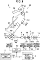
- the spinning machine includes plural spinning units 2 arranged side by side and a main control device 5 that performs centralized management of the spinning units 2.
- the main control device 5 includes a setting section 6 and spinning conditions (such as a count and spinning speed of a spinning yarn 10) can be set by using the setting section 6.
- an air-jet spinning device 9 spins a fiber bundle 8 conveyed from a drafting device 7 to form a spun yarn 10 and a winding section 26 winds the spun yarn 10 to form a package 50.
- each spinning unit 2 includes, sequentially from upstream to downstream, the drafting device 7, the air-jet spinning device 9, a yarn pooling device 22, a yarn joining device 23, a yarn monitoring device 25, and the winding section 26. All the parts of the spinning unit 2 are controlled by a unit controller (controller) 90 arranged in the spinning unit 2. All the parts of the spinning unit 2 can instead be controlled by the main control device 5.
- the drafting device 7 includes, sequentially from the upstream, four draft rollers, namely, a back roller 16, a third roller 17, a middle roller (second roller) 19 with a rubber apron belt 18, and a front roller 20. Each of the draft rollers is driven to rotate at a predetermined rotation speed.
- the drafting device 7 includes plural opposing rollers arranged respectively facing the draft rollers.
- the drafting device 7 includes a front driving section (first driving section) 91 that drives the front roller 20, a middle driving section (third driving section) 92 that drives the middle roller 19, and an upstream driving section 93 that drives the third roller 17 and the back roller 16.
- Each of the driving sections is constituted by a motor (for example, a brushless motor) a rotation speed of which can be changed in accordance with a control signal of the unit controller 90.
- a motor for example, a brushless motor
- the rotation speed of each draft roller of each spinning unit 2 can be controlled independently.
- the draft rollers of plural spinning unit 2 can be simultaneously driven by a common driving source for all the spinning units 2.
- a single driving source (upstream driving section 93) drives the third roller 17 and the back roller 16.
- a driving source can, however, be arranged individually for the third roller 17 and the back roller 16 for driving the respective rollers.
- the drafting device 7 forms the fiber bundle 8 from a sliver 15 by transporting the sliver 15, supplied from a not shown sliver case via a sliver guide, sandwiched between plural draft rollers and plural opposing rollers and stretching (drafting) the sliver 15 till a predetermined fiber amount (or thickness) is attained.
- a regulating member 21 is arranged between the third roller 17 and the middle roller 19.
- a through hole is formed in the regulating member 21.
- a width of the sliver 15 being drafted is regulated when the sliver 15 passes through the through hole of the regulating member 21.
- the air-jet spinning device 9 is arranged immediately downstream of the front roller 20.
- the air-jet spinning device 9 forms the spun yarn 10 by twisting the fiber bundle 8 supplied from the drafting device 7.
- an air-jet spinning device that twists the fiber bundle 8 by the action of a swirling air current is employed.
- the air-jet spinning device 9 includes a nozzle block 30 and a hollow guide shaft 34.
- the nozzle block 30 includes a fiber guide 31, a spinning chamber 32, and a first nozzle 33.
- the hollow guide shaft 34 includes a yarn passageway 35 and a second nozzle 36.
- the structural components of the air-jet spinning device 9 are controlled by the unit controller 90.
- the fiber guide 31 guides the fiber bundle 8 drafted by the drafting device 7 toward the interior of the air-jet spinning device 9.
- a fiber guiding opening 31a and a guide needle 31b are formed in the fiber guide 31.
- the fiber bundle 8 drafted by the drafting device 7 is guided from the fiber guiding opening 31a in a state of being wound over the guide needle 31b into the spinning chamber 32.
- Air is blown from the first nozzle 33 into the spinning chamber 32 to generate the swirling air current that acts on the fiber bundle 8 present inside the spinning chamber 32.
- the hollow guide shaft 34 is a cylindrical member and has the yarn passageway 35 formed therein.
- a swirling air current is generated inside the yarn passageway 35 when air is blown from the second nozzle 36 into the yarn passageway 35.
- the direction of the swirling air current generated by the air blown from the second nozzle 36 is opposite to the direction of the swirling air current generated by the air blowing from the first nozzle 33.
- a swirling air current is generated by the air being blown from both the first nozzle 33 and the second nozzle 36.
- the fiber bundle 8 drafted by the drafting device 7 is guided into the air-jet spinning device 9 by the fiber guide 31.
- the air blown from the first nozzle 33 flows swirlingly in a feeding direction of the fiber bundle 8.
- the fiber bundle 8 acquires a loose false twist by the action of the swirling air current and is conveyed to the hollow guide shaft 34 in this state.
- the yarn passageway 35 is formed such that a cross-sectional area thereof at any given point is larger than a cross-sectional area thereof at any point upstream of the given point. Consequently, the swirling air current inside the yarn passageway 35 flows downstream. With this configuration, the fiber bundle 8 can be conveyed in the downstream direction inside the yarn passageway 35. Because the direction of the swirling air current generated inside the yarn passageway 35 is opposite to the direction of the swirling air current inside the spinning chamber 32, the fiber bundle 8 is conveyed from the hollow guide shaft 34 to the outside while being spun into a bundled fiber form. Any known spinning method can be used to perform the spinning.
- the regular spinning is performed after the yarn discharge spinning.
- the air is blown only from the first nozzle 33 to generate the swirling air current inside the spinning chamber 32. That is, when shifting from the yarn discharge spinning to the regular spinning (during the shift), air is blown from the second nozzle 36, but during the regular spinning, air is not blown from the second nozzle 36.
- the trailing ends of the fibers of the fiber bundle 8 supplied from the drafting device 7 swing around the tip of the hollow guide shaft 34 by the action of the swirling air current generated inside the spinning chamber 32. The swinging action twists the fiber bundle 8 to form the spun yarn 10.
- the spun yarn 10 passes through the yarn passageway 35 of the hollow guide shaft 34 and is conveyed to the outside of the air-jet spinning device 9 through a not shown yarn outlet located on the downstream side.
- the spun yarn 10 is formed by applying twists to the fiber bundle 8 when performing the yarn discharge spinning and the regular spinning.
- a first guide 61 (guide member, see FIG. 3 ) that guides the spun yarn 10 is arranged downstream of the air-jet spinning device 9.
- the first guide 61 guides the spun yarn 10 to the yarn pooling device 22.
- the first guide 61 is movable so that it can pull the spun yarn 10 to the yarn pooling device 22 for performing yarn joining or the like.
- the yarn pooling device 22 is arranged downstream of the first guide 61.
- the yarn pooling device 22 includes a yarn pooling roller 41, a roller driving section (second driving section) 42, a yarn hooking member 43, and a yarn amount detection sensor 44.
- the roller driving section 42 is a motor that drives the yarn pooling roller 41 to rotate.
- the roller driving section 42 is a motor (for example, a stepping motor) a rotation speed of which can be changed in accordance with a control signal of the unit controller 90.
- the spun yarn 10 is wound onto the surface of the yarn pooling roller 41 with the driving of the rotation of the yarn pooling roller 41 by the roller driving section 42.
- the spun yarn 10 is temporarily pooled by being wound around the yarn pooling roller 41.
- the yarn hooking member 43 is mounted on a downstream end portion of the yarn pooling roller 41.
- the yarn hooking member 43 is supported in a rotatable manner relatively to the yarn pooling roller 41.
- a permanent magnet is attached to any one of the yarn hooking member 43 and the yarn pooling roller 41, and a magnetic hysteresis member is attached to the other of the yarn hooking member 43 and the yarn pooling roller 41. These magnetic means generate a torque against a relative rotation of the yarn hooking member 43 with respect to the yarn pooling roller 41.
- the yarn hooking member 43 is rotated relatively to the yarn pooling roller 41 so that the spun yarn 10 wound around the yarn pooling roller 41 can be unwound.
- the yarn pooling roller 41 and the yarn hooking member 43 are integrally rotated so that the spun yarn 10 is wound around the yarn pooling roller 41.
- the yarn pooling device 22 operates such that the spun yarn 10 is unwound when the yarn tension on the downstream is increased, and the spun yarn 10 is prevented from being unwound when the yarn tension is decreased (when the spun yarn 10 is about to have a slack). With this operation, the yarn pooling device 22 can remove the slack of the spun yarn 10 and apply an appropriate tension on the spun yarn 10. Furthermore, because the yarn hooking member 43 operates to absorb a variation of the tension applied on the spun yarn 10 between the yarn pooling device 22 and the winding section 26, the variation of the tension is prevented from affecting the spun yarn 10 between the air-jet spinning device 9 and the yarn pooling device 22.
- the yarn amount detection sensor 44 is an optical sensor that detects whether a pooled amount in the yarn pooling device 22 is a predetermined amount or more.
- a second guide 62 that regulates the spun yarn 10 unwound from the yarn pooling roller 41 is arranged downstream of the yarn pooling roller 41.
- the yarn joining device 23 is arranged downstream of the second guide 62.
- the yarn joining device 23 joins the spun yarn 10 from the air-jet spinning device 9 (first yarn) and the spun yarn 10 from the package 50 (second yarn) when the spun yarn 10 is disconnected between the air-jet spinning device 9 and the package 50 due to any reason.
- the yarn joining device 23 is a splicer device that twists and joins the yarn ends by the action of a swirling air current generated by compressed air.
- the yarn joining device 23, however, is not limited to the splicer device, and can be, for example, a mechanical knotter and the like.
- the spinning unit 2 includes a catching and guiding device that guides the spun yarn 10 to the yarn joining device 23.
- the catching and guiding device is constituted by a first catching and guiding device 27 that guides the first yarn and a second catching and guiding device 28 that guides the second yarn.
- the first catching and guiding device 27 includes a base portion that is pivotably supported, and is able to pivot in a vertical direction around the base portion as a center.
- the first catching and guiding device 27 is hollow, connected to a not shown blower, and can generate a suction airflow.
- the first catching and guiding device 27 catches an end of the first yarn by pivoting downward (see FIG. 4 ). After catching the first yarn, the first catching and guiding device 27 guides the first yarn to the yarn joining device 23 by pivoting upward.
- the second catching and guiding device 28 includes a base portion that is pivotably supported, and is able to pivot in the vertical direction around the base portion as a center.
- the second catching and guiding device 28 is also hollow, connected to a not shown blower, and can generate a suction airflow.
- the second catching and guiding device 28 catches an end of the second yarn by pivoting upward (see FIG. 4 ). After catching the second yarn, the second catching and guiding device 28 guides the second yarn to the yarn joining device 23 by pivoting downward.
- the first yarn (the spun yarn 10 formed by the regular spinning) and the second yarn are joined by the yarn joining device 23 being driven with the first yarn and the second yarn guided to the yarn joining device 23. With this action, continuity of the spun yarn 10 is restored between the air-jet spinning device 9 and the package 50 and the winding of the spun yarn 10 onto the package 50 can be resumed.
- the yarn monitoring device 25 is arranged downstream of the yarn joining device 23.
- the yarn monitoring device 25 monitors a thickness of the traveling spun yarn 10 with a not shown optical transmission type sensor.
- the yarn monitoring device 25 On detecting a yarn defect (a portion of the spun yarn 10 where the thickness or the like is abnormal) in the spun yarn 10, the yarn monitoring device 25 transmits a yarn defect detection signal to the unit controller 90.
- the unit controller 90 drives a cutter 24 arranged near the yarn monitoring device 25 to cut the spun yarn 10.
- the sensor with which the yarn monitoring device 25 monitors the thickness of the spun yarn 10 is not limited to an optical transmission type sensor, and can, for example, be a capacitance type sensor. A foreign matter included in the spun yarn 10 can be detected as the yarn defect.
- the cutter 24 can be arranged inside the yarn monitoring device 25.
- the cutter 24 can be omitted, and the spun yarn 10 can be cut by stopping spinning by the air-jet spinning device 9.
- the air-jet spinning device 9 When spinning is suspended due to yarn breakage and/or yarn cutting or the like, after the spinning by the air-jet spinning device 9 is stopped, a rotation speed of the yarn pooling roller 41 is decreased and the rotation of the yarn pooling roller 41 is eventually stopped.
- the winding section 26 is arranged downstream of the yarn pooling device 22.
- the winding section 26 includes a cradle arm 52, and a winding drum 53. A direction of a yarn path from the yarn pooling device 22 to the winding section 26 is bent and guided by a downstream guide 63.
- the cradle arm 52 rotatably supports a winding tube 51 on which the spun yarn 10 is to be wound.
- the cradle arm 52 is pivotable around a base portion as a center of pivoting. With this configuration, even when a diameter of the package 50 increases with the winding of the spun yarn 10 around the winding tube 51, the winding of the spun yarn 10 can be continued properly.
- the winding drum 53 rotates while being in contact with an outer circumferential surface of the winding tube 51 or the package 50 by a driving force transmitted from a not shown winding-drum driving motor.
- a not shown traverse groove is formed on an outer circumferential surface of the winding drum 53 and the spun yarn 10 can be traversed to a predetermined width using this traverse groove.
- the winding section 26 can form the package 50 by winding the spun yarn 10 around the winding tube 51 while traversing the spun yarn 10.
- a process performed by the spinning unit 2 during the shift from the yarn discharge spinning to the regular spinning is explained below with reference to FIGS. 4 to 7C .
- the air-jet spinning device 9 When spinning is initially started or when spinning is resumed after temporary suspension due to yarn breakage or the like (that is, when the spun yarn 10 needs to be conveyed anew from the air-jet spinning device 9), the air-jet spinning device 9 performs the yarn discharge spinning.
- the spun yarn 10 formed by the air-jet spinning device 9 through the yarn discharge spinning is guided to the yarn joining device 23 by the first catching and guiding device 27, as shown in FIG. 4 .
- the spun yarn 10 formed subsequently by the air-jet spinning device 9 is guided to a position near the yarn pooling device 22 by the first guide 61. With this action, the yarn hooking member 43 of the yarn pooling device 22 can rotate with the spun yarn 10 hooked thereto.
- the yarn pooling device 22 pulls the spun yarn 10 from the air-jet spinning device 9 and pools the spun yarn 10 on the yarn pooling roller 41.
- the yarn amount detection sensor 44 detects that the pooled amount of the spun yarn 10 on the yarn pooling roller 41 has reached a predetermined amount
- the spinning unit 2 shifts from the yarn discharge spinning to the regular spinning.
- the timing at which the shift from the yarn discharge spinning to the regular spinning is made can be decided by any means other than the yarn amount detection sensor 44.
- a yarn detection sensor can be arranged inside the first catching and guiding device 27, and the shift from the yarn discharge spinning to the regular spinning can be made at the timing when the yarn detection sensor detects the spun yarn 10.
- the spinning unit 2 exerts control such that the yarn pooling roller 41, the front roller 20, and the middle roller 19 rotate at different peripheral speeds (a distance by which a point on an outer periphery of the roller progresses in a predetermined time period) during the yarn discharge spinning and during the regular spinning.
- the respective peripheral speeds of the front roller 20, the middle roller 19, and the yarn pooling roller 41 of each spinning unit 2 can be independently controlled. Consequently, the spun yarn 10 is formed at the peripheral speeds suitable for the regular spinning in the spinning unit 2 in which the regular spinning is performed and at the peripheral speeds suitable for the yarn discharge spinning in the spinning unit 2 in which the yarn discharge spinning is performed.
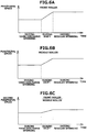
- the peripheral speeds of the yarn pooling roller 41 and the front roller 20 are constant during the yarn discharge spinning but gradually increase during the shift.
- the peripheral speeds of the front roller 20 and the yarn pooling roller 41 once again become constant at faster speeds than the peripheral speeds during the yarn discharge spinning.
- an acceleration of the yarn pooling roller 41 and the front roller 20 is uniform during the shift. The acceleration of the yarn pooling roller 41 and the front roller 20 can, however, be changed.
- the spun yarn 10 formed by the air-jet spinning device 9 is wound on the yarn pooling roller 41.
- the spun yarn 10 is subjected to excessive tension, resulting in the breakage of the spun yarn 10.
- the peripheral speed of the yarn pooling roller 41 is slower than the peripheral speed of the front roller 20, slackening of the spun yarn 10 occurs.
- a change mode (which determines how the peripheral speed is to be changed) of the peripheral speed of the yarn pooling roller 41 and a change mode of the peripheral speed of the front roller 20 during the shift are same.
- the front driving section 91 and the roller driving section 42 are controlled such that the peripheral speeds of the front roller 20 and the yarn pooling roller 41 are synchronized with each other.
- the mode in which the peripheral speeds of the yarn pooling roller 41 and the front roller 20 are changed so as not to cause breakage or slackening of the spun yarn 10 is called "same change mode".
- FIG. 5C is a graph for explaining a change in a ratio of the peripheral speed of the yarn pooling roller 41 to the peripheral speed of the front roller 20 (a value obtained by dividing the peripheral speed of the yarn pooling roller 41 by the peripheral speed of the front roller 20) (first peripheral speed ratio, feed ratio).
- first peripheral speed ratio is close to 1 for preventing breakage or slackening of the spun yarn 10.
- the first peripheral speed ratio is greater than 1 or less than 1.
- the first peripheral speed ratio has been adjusted to be greater than 1 during the yarn discharge spinning and less than 1 during the regular spinning.
- the peripheral speeds of the front roller 20 and the yarn pooling roller 41 during the shift can be decreased, i.e., reverse to what is shown in FIGS. 5A and 5B .
- the first peripheral speed ratio can be adjusted to be less than 1 during the yarn discharge spinning and greater than 1 during the regular spinning, i.e., reverse to what is shown in FIG. 5C .
- the peripheral speed of the middle roller 19 is constant during the yarn discharge spinning, gradually increases during the shift, and during the regular spinning once again becomes constant at a faster speed than the peripheral speed during the yarn discharge spinning.
- the success rate during the yarn discharge spinning also depends on the fiber amount of the fiber bundle 8 supplied to the air-jet spinning device 9. Consequently, for example, changing the peripheral speeds of the back roller 16 and the third roller 17 during the yarn discharge spinning can be considered as an approach for adjusting the fiber amount of the fiber bundle 8 supplied to the air-jet spinning device 9.
- the peripheral speeds of the back roller 16 and the third roller 17 are relatively slower, even with a small amount of change of the peripheral speeds, there is a drastic change in the fiber amount of the fiber bundle 8 supplied to the air-jet spinning device 9. Consequently, the success rate during the yarn discharge spinning reduces.
- the fiber amount of the fiber bundle 8 supplied to the middle roller 19 also changes drastically. Hence, for example, when there is an increase in the fiber amount of the fiber bundle 8 supplied to the middle roller 19, the fiber bundle 8 can get caught in the regulating member 21 arranged between the third roller 17 and the middle roller 19.
- the fiber amount of the fiber bundle 8 supplied to the air-jet spinning device 9 is adjusted by changing a ratio of the peripheral speed of the front roller 20 to the peripheral speed of the middle roller 19 (a value obtained by dividing the peripheral speed of the front roller 20 by the peripheral speed of the middle roller 19) (second peripheral speed ratio, main draft ratio).
- the spinning unit 2 controls the front driving section 91 and the middle driving section 92 so as to realize a predetermined second peripheral speed ratio. With this control, the fiber amount of the fiber bundle 8 supplied to the air-jet spinning device 9 or the like is prevented from changing drastically even if there is a slight shift in the value of the peripheral speed set for the front roller 20 or the middle roller 19.
- the spinning unit 2 increases the speed of the front roller 20 and the middle roller 19 during the shift.
- the preferred values of the second peripheral speed ratio during the yarn discharge spinning and during the regular spinning differ.
- the spinning unit 2 changes the peripheral speeds of the front roller 20 and the middle roller 19 to realize a preferred second peripheral speed ratio based on the yarn count or the like of the spun yarn 10.
- the peripheral speeds of the front roller 20 and the middle roller 19 are changed such that the second peripheral speed ratio during the regular spinning is greater than the second peripheral speed ratio during the yarn discharge spinning.
- the peripheral speeds of the front roller 20 and the middle roller 19 during the shift can be decreased, i.e., reverse to what is shown in FIGS. 6A and 6B .
- the second peripheral speed ratio during the regular spinning can be adjusted to be less than the second peripheral speed ratio during the yarn discharge spinning, i.e., reverse to what is shown in FIG. 6C .
- the peripheral speeds of the yarn pooling roller 41, the front roller 20, and the middle roller 19 are changed.
- the peripheral speeds can be set automatically based on the spinning conditions or the like entered by an operator, or can be set by the operator.
- the operator can specify the peripheral speed of each roller by entering a predetermined value in the setting section 6 of the main control device 5.
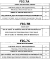
- FIGS. 7A to 7C are tables listing setting parameters that can be set in the setting section 6. As shown in FIGS. 7A to 7C , setting parameters can be set for the yarn discharge spinning, for the shift, and for the regular spinning.
- the first peripheral speed ratio and the second peripheral speed ratio can also be set as the setting parameters for the yarn discharge spinning and the regular spinning.
- the operator can set the peripheral speeds or the peripheral speed ratio by selecting a setting parameter and entering a desired value.
- the remaining parameter setting is automatically entered. The same is the case with the peripheral speed of the front roller 20, the peripheral speed of the middle roller 19, and the second peripheral speed ratio.
- a rate of change of the peripheral speeds of the yarn pooling roller 41, the front roller 20, and the middle roller 19 can be set as a setting parameter for the shift.
- the rate of change of the peripheral speed is a value that indicates the acceleration by which the peripheral speed of the yarn pooling roller 41 and the like is to be changed (or the time period in which the shift from the yarn discharge spinning to the regular spinning is to be made).
- Significantly increasing or decreasing the first peripheral speed ratio or the second peripheral speed ratio can result in undesirable consequences, such as yarn breakage, yarn slackening, a drastic increase or decrease in the fiber amount of the fiber bundle 8 and the like.
- the present embodiment allows the setting of a single rate of change of the peripheral speed for the yarn pooling roller 41, the front roller 20, and the middle roller 19.
- the setting parameters can be set by the operator by entering specific values or selecting desired levels from among plural levels.
- the spun yarn 10 can be wound under conditions suitable for the yarn count of the spun yarn 10 and the intended yarn specifications by setting the numerous setting parameters as explained above.
- the spinning machine includes the drafting device 7, the air-jet spinning device 9, and the yarn pooling roller 41.
- the drafting device 7 includes plural draft rollers, including the front roller 20, and drafts the fiber bundle 8.
- the air-jet spinning device 9 performs spinning whereby the spun yarn 10 is formed by twisting the fiber bundle 8 drafted by the drafting device 7.
- the yarn pooling roller 41 pools the spun yarn 10 formed by the air-jet spinning device 9 by winding the spun yarn 10 around the surface thereof.
- the peripheral speed of the front roller 20 during the yarn discharge spinning and during the regular spinning performed after the yarn discharge spinning differs.
- the peripheral speed of the yarn pooling roller 41 during the yarn discharge spinning and during the regular spinning differs. That is, in the time period from a time point when the yarn discharge spinning ends to a time point when the regular spinning starts, the spinning machine increases or decreases the peripheral speed of the front roller 20 and the peripheral speed of the yarn pooling roller 41.
- productivity can be enhanced without reducing the success rate of the yarn discharge spinning.
- the peripheral speed of not only the front roller 20 but also the yarn pooling roller 41 yarn breakage or yarn slackening that accompanies a change in the peripheral speed of the front roller 20 can be prevented.
- the change mode of the peripheral speed of the front roller 20 and the change mode of the peripheral speed of the yarn pooling roller 41 are same in the time period from the time point when the yarn discharge spinning ends to the time point when the regular spinning starts.
- the drafting device 7 includes the middle roller 19 that is arranged second from downstream.
- the peripheral speed of the middle roller 19 during the yarn discharge spinning and during the regular spinning differs.
- the draft ratio of, for example, the middle roller 19 and the front roller 20 can be changed by changing the peripheral speed of the middle roller 19. Accordingly, the fiber amount of the fiber bundle 8 being transported can be adjusted. Unlike the adjustment of the fiber amount of the fiber bundle 8 with the back roller 16 or the like, an increase or decrease in the quantity of the fiber amount of the fiber bundle 8 can be minimized by changing the peripheral speed of the middle roller 19. Hence, the fiber bundle 8 can be prevented from getting caught in the regulating member 21.
- the yarn pooling roller 41, the front roller 20, and the middle roller 19 are driven by different driving sections.
- at least two of the above rollers can be driven by the same driving section.
- the setting section 6 can be arranged in the main control device 5 as arranged in the above embodiment or can be arranged individually for each spinning unit 2.
- a single controller for controlling all the driving sections can be arranged in the main control device 5 or the controller can be arranged individually for each spinning unit 2 or for each driving section.
- the present invention is applied to a spinning machine in which the package 50 is formed at a position that is above the spinning unit 2.
- the present invention can, however, be applied to a spinning machine in which the package 50 is formed at a position below the spinning unit 2 (Japanese Patent Application Laid-open No. 2010-77576 or the like).
- a spinning machine includes a drafting device, an air-jet spinning device, and a yarn pooling roller.
- the drafting device includes plural draft rollers, including a front roller, and drafts a fiber bundle.
- the air-jet spinning device performs spinning whereby a yarn is formed by twisting the fiber bundle drafted by the drafting device.
- the yarn pooling roller pools the yarn formed by the air-jet spinning device by winding the yarn around a surface thereof.
- a peripheral speed of the front roller during yarn discharge spinning and during regular spinning performed after the yarn discharge spinning is different.
- a peripheral speed of the yarn pooling roller during the yarn discharge spinning and during the regular spinning is different.
- the spinning machine in a time period from a time point when the yarn discharge spinning ends to a time point when the regular spinning starts, the spinning machine increases or decreases the peripheral speeds of the front roller and the yarn pooling roller.
- the yarn discharge spinning can be performed at a spinning speed suitable for the yarn discharge spinning and the regular spinning can be performed at a spinning speed suitable for the regular spinning.
- productivity can be enhanced without reducing the success rate of the yarn discharge spinning.
- the yarn pooling roller is arranged such that it can pull the yarn from the air-jet spinning device and pool the yarn.
- the yarn pooling roller pulls the yarn from the air-jet spinning device.
- the peripheral speed of the yarn pooling roller by changing the peripheral speed of the yarn pooling roller, yarn breakage or yarn slackening that accompanies a change in the peripheral speed of the front roller can be more reliably prevented.
- the spinning machine includes a first driving section that drives the front roller to rotate and a second driving section that drives the yarn pooling roller to rotate.
- the front roller and the yarn pooling roller can be driven at different peripheral speeds with a simple structure and without requiring a speed reduction gear or the like.
- the spinning machine includes plural spinning units.
- Each of the spinning units includes the first driving section and the second driving section.
- the first driving section and the second driving section of each spinning unit are capable of performing driving independently of the first driving section and the second driving section of other spinning units.
- the peripheral speeds of the front roller and the yarn pooling roller in each spinning unit can be independently controlled.
- the spinning unit that performs the regular spinning can form the yarn at a peripheral speed that is suitable for the regular spinning and the spinning unit that performs the yarn discharge spinning can form the yarn at a peripheral speed that is suitable for the yarn discharge spinning.
- the peripheral speed of the front roller during the yarn discharge spinning is slower than the peripheral speed of the front roller during the regular spinning and the peripheral speed of the yarn pooling roller during the yarn discharge spinning is slower than the peripheral speed of the yarn pooling roller during the regular spinning.
- a change mode of the peripheral speed of the front roller and a change mode of the peripheral speed of the yarn pooling roller are same in the time period from the time point when the yarn discharge spinning ends to the time point when the regular spinning starts.
- the spinning machine includes a setting section that sets a rate of change of the peripheral speed of the front roller and a rate of change of the peripheral speed of the yarn pooling roller for the time period from the time point when the yarn discharge spinning ends to the time point when the regular spinning starts.
- the rate of change of the peripheral speeds can be adjusted by taking into consideration the time period from the end of the yarn discharge spinning to the start of the regular spinning, a load on the yarn, and the like.
- a ratio of the peripheral speed of the yarn pooling roller to the peripheral speed of the front roller during the yarn discharge spinning and during the regular spinning differs.
- the fiber bundle can be drafted and the yarn can be pulled from the air-jet spinning device at the ratio of peripheral speeds suitable for a count of the yarn, the spinning speed, and the like.
- a second roller arranged second from the downstream is included in the plural draft rollers of the drafting device.
- a peripheral speed of the second roller during the yarn discharge spinning and during the regular spinning is different.
- a draft ratio of the second roller and the front roller can be changed.
- a fiber amount of the fiber bundle conveyed to the drafting device can be adjusted.
- the spinning machine includes a third driving section that drives the second roller.
- the peripheral speeds of the front roller and the second roller can be individually changed with a simple structure and without requiring a speed reduction gear or the like.
- the peripheral speed of the front roller and the peripheral speed of the second roller change and a ratio of the peripheral speed of the front roller to the peripheral speed of the second roller changes.
- the spinning machine includes a controller that controls at least the drafting device and the yarn pooling roller.
- the peripheral speed of the front roller included in the drafting device that drafts the fiber bundle is caused to differ during yarn discharge spinning performed by the air-jet spinning device that performs spinning to form the yarn by twisting the fiber bundle and during regular spinning performed by the air-jet spinning device after the yarn discharge spinning.
- the peripheral speed of the yarn pooling roller that pools the yarn by winding the yarn formed by the air-jet spinning device on a surface thereof is caused to differ during the yarn discharge spinning and during the regular spinning.
- productivity can be enhanced without reducing the success rate of yarn discharge spinning.
- the peripheral speed of not only the front roller but also the yarn pooling roller yarn breakage or yarn slackening that accompanies a change in the peripheral speed of the front roller can be prevented.
Claims (14)
- Spinnmaschine, umfassend:ein Ziehwerk (7), das mehrere Ziehwalzen (16, 17, 19, 20) einschließt, einschließlich einer vorderen Walze (20), und angepasst ist, um ein Faserbündel (8) zu ziehen;eine Luftspinnvorrichtung (9), die angepasst ist, um ein Spinnen durchzuführen, um ein Garn (10) durch Verdrehen des Faserbündels (8), das durch das Ziehwerk (7) gezogen wurde, zu bilden; undeine Garn-Zusammenführwalze (41), die angepasst ist, um das Garn (10) durch Wickeln des Garns (10), das durch die Luftspinnvorrichtung (9) auf der Oberfläche davon gebildet wird, zusammenzuführen, während das Garn (10) von der Luftspinnvorrichtung (9) gezogen wird, dadurch gekennzeichnet, dasseine periphere Geschwindigkeit der vorderen Walze (20) während eines Garnabgabespinnens und während eines regulären Spinnens, das nach dem Garnabgabespinnen durchgeführt wird, unterschiedlich ist, undeine periphere Geschwindigkeit der Garn-Zusammenführwalze (41) während des Garnabgabespinnens und während des regulären Spinnens, das nach dem Garnabgabespinnen durchgeführt wird, unterschiedlich ist; wobeieine periphere Geschwindigkeit der vorderen Walze (20) während des Garnabgabespinnens langsamer ist als eine periphere Geschwindigkeit der vorderen Walze (20) während des regulären Spinnens, undeine periphere Geschwindigkeit der Garn-Zusammenführwalze (41) während des Garnabgabespinnens langsamer ist als eine periphere Geschwindigkeit der Garn-Zusammenführwalze (41) während des regulären Spinnens.
- Spinnmaschine, umfassend:ein Ziehwerk (7), das mehrere Ziehwalzen (16. 17, 19, 20) einschließt, einschließlich einer vorderen Walze (20), und angepasst ist, um ein Faserbündel (8) zu ziehen;eine Luftspinnvorrichtung (9), die angepasst ist, um ein Spinnen durchzuführen, um ein Garn (10) durch Verdrehen des Faserbündels (8), das durch das Ziehwerk (7) gezogen wurde, zu bilden; undeine Garn-Zusammenführwalze (41), die angepasst ist, um das Garn (10) durch Wickeln des Garns (10), das durch die Luftspinnvorrichtung (9) auf der Oberfläche davon gebildet wird, zusammenzuführen, während das Garn (10) von der Luftspinnvorrichtung (9) gezogen wird, dadurch gekennzeichnet, dasseine periphere Geschwindigkeit der vorderen Walze (20) in einem Zeitraum von einem Zeitpunkt, zu dem das Garnabgabespinnen endet, bis zu einem Zeitpunkt, zu dem das reguläre Spinnen beginnt, erhöht wird, undeine periphere Geschwindigkeit der Garn-Zusammenführwalze (41) in dem Zeitraum von einem Zeitpunkt, zu dem das Garnabgabespinnen endet, bis zu einem Zeitpunkt, zu dem das reguläre Spinnen beginnt, erhöht wird; wobeieine periphere Geschwindigkeit der vorderen Walze (20) während des Garnabgabespinnens langsamer ist als eine periphere Geschwindigkeit der vorderen Walze (20) während des regulären Spinnens, undeine periphere Geschwindigkeit der Garn-Zusammenführwalze (41) während des Garnabgabespinnens langsamer ist als eine periphere Geschwindigkeit der Garn-Zusammenführwalze (41) während des regulären Spinnens.
- Spinnmaschine nach Anspruch 1 oder Anspruch 2, weiter umfassend:einen ersten Antriebsabschnitt (91), der angepasst ist, um die vordere Walze (20) anzutreiben, sodass sie rotiert; undeinen zweiten Antriebsabschnitt (42), der angepasst ist, um die Garn-Zusammenführwalze (41) anzutreiben, sodass sie rotiert.
- Spinnmaschine nach Anspruch 3, weiter umfassend mehrere Spinneinheiten (2), von denen jede den ersten Antriebsabschnitt (91) und den zweiten Antriebsabschnitt (42) einschließt,
wobei der erste Antriebsabschnitt (91) und der zweite Antriebsabschnitt (42) jeder Spinneinheit (2) angepasst sind, um unabhängig voneinander den Antrieb des ersten Antriebsabschnitts (91) und des zweiten Antriebsabschnitts (42) anderer Spinneinheiten (2) durchzuführen. - Spinnmaschine nach einem der Ansprüche 1 bis 4, wobei ein Änderungsmodus der peripheren Geschwindigkeit der vorderen Walze (20) und ein Änderungsmodus der peripheren Geschwindigkeit der Garn-Zusammenführwalze (41) in dem Zeitraum von dem Zeitpunkt, zu dem das Garnabgabespinnen endet, bis zu dem Zeitpunkt, zu dem das reguläre Spinnen beginnt, gleich sind.
- Spinnmaschine nach Anspruch 5, weiter umfassend einen Regelabschnitt (6), der angepasst ist, um eine Änderungsrate der peripheren Geschwindigkeit der vorderen Walze (20) und eine Änderungsrate der peripheren Geschwindigkeit der Garn-Zusammenführwalze (41) für den Zeitraum von dem Zeitpunkt, zu dem das Garnabgabespinnen endet, bis zu dem Zeitpunkt, zu dem das reguläre Spinnen beginnt, zu regeln.
- Spinnmaschine nach einem der Ansprüche 1 bis 6, wobei ein Verhältnis der peripheren Geschwindigkeit der Garn-Zusammenführwalze (41) zu der peripheren Geschwindigkeit der vorderen Walze (20) während des Garnabgabespinnens und während des regulären Spinnens unterschiedlich ist.
- Spinnmaschine nach einem der Ansprüche 1 bis 7, wobei eine zweite Walze (19), die als Zweites von der stromabwärts angeordnet ist, in den mehreren Ziehwalzen (16, 17, 19, 20) des Ziehwerks (7) eingeschlossen ist, und eine periphere Geschwindigkeit der zweiten Walze (19) während des Garnabgabespinnens und während des regulären Spinnens unterschiedlich ist.
- Spinnmaschine nach Anspruch 8, weiter umfassend einen dritten Antriebsabschnitt (92), der angepasst ist, um die zweite Walze (19) anzutreiben.
- Spinnmaschine nach Anspruch 8 oder Anspruch 9, wobei in dem Zeitraum von dem Zeitpunkt, zu dem das Garnabgabespinnen endet, bis zu dem Zeitpunkt, zu dem das reguläre Spinnen beginnt, die periphere Geschwindigkeit der vorderen Walze (20) und die periphere Geschwindigkeit der zweiten Walze (19) sich verändern und ein Verhältnis der peripheren Geschwindigkeit der vorderen Walze (20) zu der peripheren Geschwindigkeit der zweiten Walze (19) sich verändert.
- Spinnmaschine nach einem der Ansprüche 1 bis 10, weiter umfassend eine Steuerung (90) die angepasst ist, um mindestens das Ziehwerk (7) und die Garn-Zusammenführwalze (41) zu steuern.
- Spinnmaschine nach einem der Ansprüche 3 bis 11, wobei der erste Antriebsabschnitt (91) und der zweite Antriebsabschnitt (42) so gesteuert werden, dass die peripheren Geschwindigkeiten der vorderen Walze (20) und der Garn-Zusammenführwalze (41) miteinander synchronisiert sind.
- Spinnverfahren, umfassend:Verursachen, dass eine periphere Geschwindigkeit einer vorderen Walze (20), die in einem Ziehwerk (7) eingeschlossen ist, das angepasst ist, um ein Faserbündel (8) zu ziehen, sich während eines Garnabgabespinnens, das durch eine Luftspinnvorrichtung (9) durchgeführt wird, die angepasst ist, das Spinnen durchzuführen, um ein Garn (10) durch Verdrehen des Faserbündels (8) zu bilden, und während des regulären Spinnens, das durch die Luftspinnvorrichtung (9) durchgeführt wird, nachdem das Garnabgabespinnen beendet wurde, unterscheidet; undVerursachen, dass eine periphere Geschwindigkeit einer Garn-Zusammenführwalze (41), die angepasst ist, um das Garn (10) durch Wickeln des Garns (10), das durch die Luftspinnvorrichtung (9) auf einer Oberfläche davon gebildet wird, während das Garn (10) von der Luftspinnvorrichtung (9) gezogen wird, sich während des Garnabgabespinnens und während des regulären Spinnens unterscheidet; wobei eine periphere Geschwindigkeit der vorderen Walze (20) während des Garnabgabespinnens langsamer ist als eine periphere Geschwindigkeit der vorderen Walze (20) während des regulären Spinnens, und eine periphere Geschwindigkeit der Garn-Zusammenführwalze (41) während des Garnabgabespinnens langsamer ist als eine periphere Geschwindigkeit der Garn-Zusammenführwalze (41) während des regulären Spinnens.
- Spinnverfahren nach Anspruch 13, wobei die peripheren Geschwindigkeiten der vorderen Walze (20) und der Garn-Zusammenführwalze (41) miteinander synchronisiert sind.
Applications Claiming Priority (1)
| Application Number | Priority Date | Filing Date | Title |
|---|---|---|---|
| JP2014150306A JP2016023391A (ja) | 2014-07-24 | 2014-07-24 | 紡績機及び紡績方法 |
Publications (3)
| Publication Number | Publication Date |
|---|---|
| EP2977493A2 EP2977493A2 (de) | 2016-01-27 |
| EP2977493A3 EP2977493A3 (de) | 2016-06-01 |
| EP2977493B1 true EP2977493B1 (de) | 2018-11-28 |
Family
ID=53433116
Family Applications (1)
| Application Number | Title | Priority Date | Filing Date |
|---|---|---|---|
| EP15172508.2A Not-in-force EP2977493B1 (de) | 2014-07-24 | 2015-06-17 | Spinnmaschine und spinnverfahren |
Country Status (3)
| Country | Link |
|---|---|
| EP (1) | EP2977493B1 (de) |
| JP (1) | JP2016023391A (de) |
| CN (1) | CN105297197B (de) |
Families Citing this family (5)
| Publication number | Priority date | Publication date | Assignee | Title |
|---|---|---|---|---|
| JP2018090923A (ja) * | 2016-12-01 | 2018-06-14 | 村田機械株式会社 | 紡績機及び紡績方法 |
| CN106835421A (zh) * | 2016-12-14 | 2017-06-13 | 马鞍山金姿纺织装饰用品有限公司 | 一种纺织机纺织方法 |
| EP3505661A1 (de) * | 2017-12-28 | 2019-07-03 | Murata Machinery, Ltd. | Spinnmaschine und spinnverfahren |
| CN109632486A (zh) * | 2019-01-14 | 2019-04-16 | 长乐恒申合纤科技有限公司 | 一种氨纶退绕性能检测装置及其方法 |
| CN113550033A (zh) * | 2021-07-28 | 2021-10-26 | 忠华集团有限公司 | 一种氨纶丝托辊异速检测方法、装置及电子设备 |
Family Cites Families (7)
| Publication number | Priority date | Publication date | Assignee | Title |
|---|---|---|---|---|
| JP3196706B2 (ja) * | 1997-09-22 | 2001-08-06 | 村田機械株式会社 | 紡績機の運転方法 |
| JP3575470B2 (ja) * | 2002-03-18 | 2004-10-13 | 村田機械株式会社 | 紡績方法及びその装置 |
| JP4019984B2 (ja) * | 2003-03-17 | 2007-12-12 | 村田機械株式会社 | 紡績機 |
| EP2423142B1 (de) * | 2003-03-13 | 2013-05-01 | Murata Kikai Kabushiki Kaisha | Verfahren zum Betrieb eines Garnwicklers |
| JP2010077576A (ja) | 2008-09-29 | 2010-04-08 | Murata Machinery Ltd | 紡績機 |
| JP5924860B2 (ja) * | 2010-12-03 | 2016-05-25 | 株式会社豊田自動織機 | 前紡工程のドラフト装置の制御方法及び制御装置 |
| JP2013067447A (ja) * | 2011-09-20 | 2013-04-18 | Murata Machinery Ltd | 糸貯留装置、紡績ユニット及び紡績機 |
-
2014
- 2014-07-24 JP JP2014150306A patent/JP2016023391A/ja active Pending
-
2015
- 2015-06-17 EP EP15172508.2A patent/EP2977493B1/de not_active Not-in-force
- 2015-07-02 CN CN201510381904.8A patent/CN105297197B/zh active Active
Non-Patent Citations (1)
| Title |
|---|
| None * |
Also Published As
| Publication number | Publication date |
|---|---|
| EP2977493A2 (de) | 2016-01-27 |
| CN105297197B (zh) | 2019-11-22 |
| JP2016023391A (ja) | 2016-02-08 |
| EP2977493A3 (de) | 2016-06-01 |
| CN105297197A (zh) | 2016-02-03 |
Similar Documents
| Publication | Publication Date | Title |
|---|---|---|
| EP2169096B9 (de) | Spinnmaschine | |
| EP2302115B1 (de) | Spinnmaschinesteuerungsverfahren | |
| EP2977493B1 (de) | Spinnmaschine und spinnverfahren | |
| JP6080153B2 (ja) | 紡績機及び紡績機における糸の製造を中断する方法 | |
| EP1460015B1 (de) | Spulmaschine für Faden | |
| EP2284300B1 (de) | Spinnmaschine und Garnentfernungsverfahren zum Entfernen von verbleibendem Garn auf der Garnzusammentragungsrolle | |
| EP2298971B1 (de) | Spinnmaschine mit Garnspeicher-Rolle | |
| EP2727870A2 (de) | Garnwickelmaschine und Garnwickelverfahren | |
| EP2075358A2 (de) | Spinnmaschine | |
| EP3072840B1 (de) | Garnwickelmaschine und garnwickelverfahren | |
| JP2010180007A (ja) | 糸処理方法及び紡績機 | |
| CN106567170B (zh) | 纺织机以及控制装置 | |
| EP2966200B1 (de) | Spinnmaschine und spinnverfahren | |
| EP2805907B1 (de) | Garnwicklungsmaschine | |
| EP2573019B1 (de) | Spinneinheit mit einer Garnspeichervorrichtung, und Spinnmaschine | |
| JP2008024438A (ja) | 糸巻取装置 | |
| JP4082250B2 (ja) | 紡績機の糸弛み取り装置 | |
| JP3888318B2 (ja) | 紡績機 | |
| JP2017071865A (ja) | 紡績機 | |
| JP3952976B2 (ja) | 糸継ぎ装置を備えた紡績機 | |
| JP4019984B2 (ja) | 紡績機 | |
| JP3888320B2 (ja) | 紡績機 | |
| JP2022085990A (ja) | 紡績機及び紡績方法 | |
| JP2004339612A (ja) | 紡績機 | |
| JP2009046779A (ja) | 粗糸ボビン保持装置 |
Legal Events
| Date | Code | Title | Description |
|---|---|---|---|
| PUAI | Public reference made under article 153(3) epc to a published international application that has entered the european phase |
Free format text: ORIGINAL CODE: 0009012 |
|
| AK | Designated contracting states |
Kind code of ref document: A2 Designated state(s): AL AT BE BG CH CY CZ DE DK EE ES FI FR GB GR HR HU IE IS IT LI LT LU LV MC MK MT NL NO PL PT RO RS SE SI SK SM TR |
|
| AX | Request for extension of the european patent |
Extension state: BA ME |
|
| PUAL | Search report despatched |
Free format text: ORIGINAL CODE: 0009013 |
|
| AK | Designated contracting states |
Kind code of ref document: A3 Designated state(s): AL AT BE BG CH CY CZ DE DK EE ES FI FR GB GR HR HU IE IS IT LI LT LU LV MC MK MT NL NO PL PT RO RS SE SI SK SM TR |
|
| AX | Request for extension of the european patent |
Extension state: BA ME |
|
| RIC1 | Information provided on ipc code assigned before grant |
Ipc: D01H 1/30 20060101AFI20160425BHEP Ipc: D01H 13/10 20060101ALI20160425BHEP Ipc: D01H 1/115 20060101ALI20160425BHEP |
|
| 17P | Request for examination filed |
Effective date: 20160608 |
|
| RBV | Designated contracting states (corrected) |
Designated state(s): AL AT BE BG CH CY CZ DE DK EE ES FI FR GB GR HR HU IE IS IT LI LT LU LV MC MK MT NL NO PL PT RO RS SE SI SK SM TR |
|
| GRAP | Despatch of communication of intention to grant a patent |
Free format text: ORIGINAL CODE: EPIDOSNIGR1 |
|
| STAA | Information on the status of an ep patent application or granted ep patent |
Free format text: STATUS: GRANT OF PATENT IS INTENDED |
|
| INTG | Intention to grant announced |
Effective date: 20180718 |
|
| GRAS | Grant fee paid |
Free format text: ORIGINAL CODE: EPIDOSNIGR3 |
|
| GRAA | (expected) grant |
Free format text: ORIGINAL CODE: 0009210 |
|
| STAA | Information on the status of an ep patent application or granted ep patent |
Free format text: STATUS: THE PATENT HAS BEEN GRANTED |
|
| AK | Designated contracting states |
Kind code of ref document: B1 Designated state(s): AL AT BE BG CH CY CZ DE DK EE ES FI FR GB GR HR HU IE IS IT LI LT LU LV MC MK MT NL NO PL PT RO RS SE SI SK SM TR |
|
| REG | Reference to a national code |
Ref country code: CH Ref legal event code: EP |
|
| REG | Reference to a national code |
Ref country code: AT Ref legal event code: REF Ref document number: 1070336 Country of ref document: AT Kind code of ref document: T Effective date: 20181215 |
|
| REG | Reference to a national code |
Ref country code: DE Ref legal event code: R096 Ref document number: 602015020288 Country of ref document: DE |
|
| REG | Reference to a national code |
Ref country code: IE Ref legal event code: FG4D |
|
| REG | Reference to a national code |
Ref country code: NL Ref legal event code: MP Effective date: 20181128 |
|
| REG | Reference to a national code |
Ref country code: LT Ref legal event code: MG4D |
|
| REG | Reference to a national code |
Ref country code: AT Ref legal event code: MK05 Ref document number: 1070336 Country of ref document: AT Kind code of ref document: T Effective date: 20181128 |
|
| PG25 | Lapsed in a contracting state [announced via postgrant information from national office to epo] |
Ref country code: ES Free format text: LAPSE BECAUSE OF FAILURE TO SUBMIT A TRANSLATION OF THE DESCRIPTION OR TO PAY THE FEE WITHIN THE PRESCRIBED TIME-LIMIT Effective date: 20181128 Ref country code: BG Free format text: LAPSE BECAUSE OF FAILURE TO SUBMIT A TRANSLATION OF THE DESCRIPTION OR TO PAY THE FEE WITHIN THE PRESCRIBED TIME-LIMIT Effective date: 20190228 Ref country code: LT Free format text: LAPSE BECAUSE OF FAILURE TO SUBMIT A TRANSLATION OF THE DESCRIPTION OR TO PAY THE FEE WITHIN THE PRESCRIBED TIME-LIMIT Effective date: 20181128 Ref country code: HR Free format text: LAPSE BECAUSE OF FAILURE TO SUBMIT A TRANSLATION OF THE DESCRIPTION OR TO PAY THE FEE WITHIN THE PRESCRIBED TIME-LIMIT Effective date: 20181128 Ref country code: LV Free format text: LAPSE BECAUSE OF FAILURE TO SUBMIT A TRANSLATION OF THE DESCRIPTION OR TO PAY THE FEE WITHIN THE PRESCRIBED TIME-LIMIT Effective date: 20181128 Ref country code: NO Free format text: LAPSE BECAUSE OF FAILURE TO SUBMIT A TRANSLATION OF THE DESCRIPTION OR TO PAY THE FEE WITHIN THE PRESCRIBED TIME-LIMIT Effective date: 20190228 Ref country code: IS Free format text: LAPSE BECAUSE OF FAILURE TO SUBMIT A TRANSLATION OF THE DESCRIPTION OR TO PAY THE FEE WITHIN THE PRESCRIBED TIME-LIMIT Effective date: 20190328 Ref country code: FI Free format text: LAPSE BECAUSE OF FAILURE TO SUBMIT A TRANSLATION OF THE DESCRIPTION OR TO PAY THE FEE WITHIN THE PRESCRIBED TIME-LIMIT Effective date: 20181128 Ref country code: AT Free format text: LAPSE BECAUSE OF FAILURE TO SUBMIT A TRANSLATION OF THE DESCRIPTION OR TO PAY THE FEE WITHIN THE PRESCRIBED TIME-LIMIT Effective date: 20181128 |
|
| PG25 | Lapsed in a contracting state [announced via postgrant information from national office to epo] |
Ref country code: AL Free format text: LAPSE BECAUSE OF FAILURE TO SUBMIT A TRANSLATION OF THE DESCRIPTION OR TO PAY THE FEE WITHIN THE PRESCRIBED TIME-LIMIT Effective date: 20181128 Ref country code: PT Free format text: LAPSE BECAUSE OF FAILURE TO SUBMIT A TRANSLATION OF THE DESCRIPTION OR TO PAY THE FEE WITHIN THE PRESCRIBED TIME-LIMIT Effective date: 20190328 Ref country code: SE Free format text: LAPSE BECAUSE OF FAILURE TO SUBMIT A TRANSLATION OF THE DESCRIPTION OR TO PAY THE FEE WITHIN THE PRESCRIBED TIME-LIMIT Effective date: 20181128 Ref country code: RS Free format text: LAPSE BECAUSE OF FAILURE TO SUBMIT A TRANSLATION OF THE DESCRIPTION OR TO PAY THE FEE WITHIN THE PRESCRIBED TIME-LIMIT Effective date: 20181128 Ref country code: GR Free format text: LAPSE BECAUSE OF FAILURE TO SUBMIT A TRANSLATION OF THE DESCRIPTION OR TO PAY THE FEE WITHIN THE PRESCRIBED TIME-LIMIT Effective date: 20190301 |
|
| PG25 | Lapsed in a contracting state [announced via postgrant information from national office to epo] |
Ref country code: NL Free format text: LAPSE BECAUSE OF FAILURE TO SUBMIT A TRANSLATION OF THE DESCRIPTION OR TO PAY THE FEE WITHIN THE PRESCRIBED TIME-LIMIT Effective date: 20181128 |
|
| PG25 | Lapsed in a contracting state [announced via postgrant information from national office to epo] |
Ref country code: DK Free format text: LAPSE BECAUSE OF FAILURE TO SUBMIT A TRANSLATION OF THE DESCRIPTION OR TO PAY THE FEE WITHIN THE PRESCRIBED TIME-LIMIT Effective date: 20181128 Ref country code: IT Free format text: LAPSE BECAUSE OF FAILURE TO SUBMIT A TRANSLATION OF THE DESCRIPTION OR TO PAY THE FEE WITHIN THE PRESCRIBED TIME-LIMIT Effective date: 20181128 Ref country code: PL Free format text: LAPSE BECAUSE OF FAILURE TO SUBMIT A TRANSLATION OF THE DESCRIPTION OR TO PAY THE FEE WITHIN THE PRESCRIBED TIME-LIMIT Effective date: 20181128 |
|
| REG | Reference to a national code |
Ref country code: DE Ref legal event code: R097 Ref document number: 602015020288 Country of ref document: DE |
|
| PG25 | Lapsed in a contracting state [announced via postgrant information from national office to epo] |
Ref country code: SK Free format text: LAPSE BECAUSE OF FAILURE TO SUBMIT A TRANSLATION OF THE DESCRIPTION OR TO PAY THE FEE WITHIN THE PRESCRIBED TIME-LIMIT Effective date: 20181128 Ref country code: RO Free format text: LAPSE BECAUSE OF FAILURE TO SUBMIT A TRANSLATION OF THE DESCRIPTION OR TO PAY THE FEE WITHIN THE PRESCRIBED TIME-LIMIT Effective date: 20181128 Ref country code: EE Free format text: LAPSE BECAUSE OF FAILURE TO SUBMIT A TRANSLATION OF THE DESCRIPTION OR TO PAY THE FEE WITHIN THE PRESCRIBED TIME-LIMIT Effective date: 20181128 Ref country code: SM Free format text: LAPSE BECAUSE OF FAILURE TO SUBMIT A TRANSLATION OF THE DESCRIPTION OR TO PAY THE FEE WITHIN THE PRESCRIBED TIME-LIMIT Effective date: 20181128 |
|
| PLBE | No opposition filed within time limit |
Free format text: ORIGINAL CODE: 0009261 |
|
| STAA | Information on the status of an ep patent application or granted ep patent |
Free format text: STATUS: NO OPPOSITION FILED WITHIN TIME LIMIT |
|
| PG25 | Lapsed in a contracting state [announced via postgrant information from national office to epo] |
Ref country code: SI Free format text: LAPSE BECAUSE OF FAILURE TO SUBMIT A TRANSLATION OF THE DESCRIPTION OR TO PAY THE FEE WITHIN THE PRESCRIBED TIME-LIMIT Effective date: 20181128 |
|
| 26N | No opposition filed |
Effective date: 20190829 |
|
| PG25 | Lapsed in a contracting state [announced via postgrant information from national office to epo] |
Ref country code: MC Free format text: LAPSE BECAUSE OF FAILURE TO SUBMIT A TRANSLATION OF THE DESCRIPTION OR TO PAY THE FEE WITHIN THE PRESCRIBED TIME-LIMIT Effective date: 20181128 |
|
| GBPC | Gb: european patent ceased through non-payment of renewal fee |
Effective date: 20190617 |
|
| REG | Reference to a national code |
Ref country code: BE Ref legal event code: MM Effective date: 20190630 |
|
| PG25 | Lapsed in a contracting state [announced via postgrant information from national office to epo] |
Ref country code: TR Free format text: LAPSE BECAUSE OF FAILURE TO SUBMIT A TRANSLATION OF THE DESCRIPTION OR TO PAY THE FEE WITHIN THE PRESCRIBED TIME-LIMIT Effective date: 20181128 |
|
| PG25 | Lapsed in a contracting state [announced via postgrant information from national office to epo] |
Ref country code: GB Free format text: LAPSE BECAUSE OF NON-PAYMENT OF DUE FEES Effective date: 20190617 Ref country code: IE Free format text: LAPSE BECAUSE OF NON-PAYMENT OF DUE FEES Effective date: 20190617 |
|
| PG25 | Lapsed in a contracting state [announced via postgrant information from national office to epo] |
Ref country code: BE Free format text: LAPSE BECAUSE OF NON-PAYMENT OF DUE FEES Effective date: 20190630 Ref country code: LU Free format text: LAPSE BECAUSE OF NON-PAYMENT OF DUE FEES Effective date: 20190617 |
|
| PG25 | Lapsed in a contracting state [announced via postgrant information from national office to epo] |
Ref country code: FR Free format text: LAPSE BECAUSE OF NON-PAYMENT OF DUE FEES Effective date: 20190630 |
|
| PGFP | Annual fee paid to national office [announced via postgrant information from national office to epo] |
Ref country code: DE Payment date: 20200618 Year of fee payment: 6 Ref country code: CH Payment date: 20200618 Year of fee payment: 6 Ref country code: CZ Payment date: 20200616 Year of fee payment: 6 |
|
| PG25 | Lapsed in a contracting state [announced via postgrant information from national office to epo] |
Ref country code: CY Free format text: LAPSE BECAUSE OF FAILURE TO SUBMIT A TRANSLATION OF THE DESCRIPTION OR TO PAY THE FEE WITHIN THE PRESCRIBED TIME-LIMIT Effective date: 20181128 |
|
| PG25 | Lapsed in a contracting state [announced via postgrant information from national office to epo] |
Ref country code: MT Free format text: LAPSE BECAUSE OF FAILURE TO SUBMIT A TRANSLATION OF THE DESCRIPTION OR TO PAY THE FEE WITHIN THE PRESCRIBED TIME-LIMIT Effective date: 20181128 Ref country code: HU Free format text: LAPSE BECAUSE OF FAILURE TO SUBMIT A TRANSLATION OF THE DESCRIPTION OR TO PAY THE FEE WITHIN THE PRESCRIBED TIME-LIMIT; INVALID AB INITIO Effective date: 20150617 |
|
| REG | Reference to a national code |
Ref country code: DE Ref legal event code: R119 Ref document number: 602015020288 Country of ref document: DE |
|
| PG25 | Lapsed in a contracting state [announced via postgrant information from national office to epo] |
Ref country code: CZ Free format text: LAPSE BECAUSE OF NON-PAYMENT OF DUE FEES Effective date: 20210617 |
|
| REG | Reference to a national code |
Ref country code: CH Ref legal event code: PL |
|
| PG25 | Lapsed in a contracting state [announced via postgrant information from national office to epo] |
Ref country code: LI Free format text: LAPSE BECAUSE OF NON-PAYMENT OF DUE FEES Effective date: 20210630 Ref country code: DE Free format text: LAPSE BECAUSE OF NON-PAYMENT OF DUE FEES Effective date: 20220101 Ref country code: CH Free format text: LAPSE BECAUSE OF NON-PAYMENT OF DUE FEES Effective date: 20210630 |
|
| PG25 | Lapsed in a contracting state [announced via postgrant information from national office to epo] |
Ref country code: MK Free format text: LAPSE BECAUSE OF FAILURE TO SUBMIT A TRANSLATION OF THE DESCRIPTION OR TO PAY THE FEE WITHIN THE PRESCRIBED TIME-LIMIT Effective date: 20181128 |