EP2977251A1 - Drive device for electric vehicle - Google Patents
Drive device for electric vehicle Download PDFInfo
- Publication number
- EP2977251A1 EP2977251A1 EP14768950.9A EP14768950A EP2977251A1 EP 2977251 A1 EP2977251 A1 EP 2977251A1 EP 14768950 A EP14768950 A EP 14768950A EP 2977251 A1 EP2977251 A1 EP 2977251A1
- Authority
- EP
- European Patent Office
- Prior art keywords
- motor
- generator
- speed reduction
- drive device
- vehicle body
- Prior art date
- Legal status (The legal status is an assumption and is not a legal conclusion. Google has not performed a legal analysis and makes no representation as to the accuracy of the status listed.)
- Withdrawn
Links
Images
Classifications
-
- B—PERFORMING OPERATIONS; TRANSPORTING
- B62—LAND VEHICLES FOR TRAVELLING OTHERWISE THAN ON RAILS
- B62D—MOTOR VEHICLES; TRAILERS
- B62D9/00—Steering deflectable wheels not otherwise provided for
- B62D9/002—Steering deflectable wheels not otherwise provided for combined with means for differentially distributing power on the deflectable wheels during cornering
-
- B—PERFORMING OPERATIONS; TRANSPORTING
- B60—VEHICLES IN GENERAL
- B60K—ARRANGEMENT OR MOUNTING OF PROPULSION UNITS OR OF TRANSMISSIONS IN VEHICLES; ARRANGEMENT OR MOUNTING OF PLURAL DIVERSE PRIME-MOVERS IN VEHICLES; AUXILIARY DRIVES FOR VEHICLES; INSTRUMENTATION OR DASHBOARDS FOR VEHICLES; ARRANGEMENTS IN CONNECTION WITH COOLING, AIR INTAKE, GAS EXHAUST OR FUEL SUPPLY OF PROPULSION UNITS IN VEHICLES
- B60K1/00—Arrangement or mounting of electrical propulsion units
-
- B—PERFORMING OPERATIONS; TRANSPORTING
- B60—VEHICLES IN GENERAL
- B60K—ARRANGEMENT OR MOUNTING OF PROPULSION UNITS OR OF TRANSMISSIONS IN VEHICLES; ARRANGEMENT OR MOUNTING OF PLURAL DIVERSE PRIME-MOVERS IN VEHICLES; AUXILIARY DRIVES FOR VEHICLES; INSTRUMENTATION OR DASHBOARDS FOR VEHICLES; ARRANGEMENTS IN CONNECTION WITH COOLING, AIR INTAKE, GAS EXHAUST OR FUEL SUPPLY OF PROPULSION UNITS IN VEHICLES
- B60K17/00—Arrangement or mounting of transmissions in vehicles
- B60K17/04—Arrangement or mounting of transmissions in vehicles characterised by arrangement, location or kind of gearing
- B60K17/16—Arrangement or mounting of transmissions in vehicles characterised by arrangement, location or kind of gearing of differential gearing
- B60K17/165—Arrangement or mounting of transmissions in vehicles characterised by arrangement, location or kind of gearing of differential gearing provided between independent half axles
-
- B—PERFORMING OPERATIONS; TRANSPORTING
- B60—VEHICLES IN GENERAL
- B60L—PROPULSION OF ELECTRICALLY-PROPELLED VEHICLES; SUPPLYING ELECTRIC POWER FOR AUXILIARY EQUIPMENT OF ELECTRICALLY-PROPELLED VEHICLES; ELECTRODYNAMIC BRAKE SYSTEMS FOR VEHICLES IN GENERAL; MAGNETIC SUSPENSION OR LEVITATION FOR VEHICLES; MONITORING OPERATING VARIABLES OF ELECTRICALLY-PROPELLED VEHICLES; ELECTRIC SAFETY DEVICES FOR ELECTRICALLY-PROPELLED VEHICLES
- B60L15/00—Methods, circuits, or devices for controlling the traction-motor speed of electrically-propelled vehicles
- B60L15/007—Physical arrangements or structures of drive train converters specially adapted for the propulsion motors of electric vehicles
-
- B—PERFORMING OPERATIONS; TRANSPORTING
- B60—VEHICLES IN GENERAL
- B60K—ARRANGEMENT OR MOUNTING OF PROPULSION UNITS OR OF TRANSMISSIONS IN VEHICLES; ARRANGEMENT OR MOUNTING OF PLURAL DIVERSE PRIME-MOVERS IN VEHICLES; AUXILIARY DRIVES FOR VEHICLES; INSTRUMENTATION OR DASHBOARDS FOR VEHICLES; ARRANGEMENTS IN CONNECTION WITH COOLING, AIR INTAKE, GAS EXHAUST OR FUEL SUPPLY OF PROPULSION UNITS IN VEHICLES
- B60K1/00—Arrangement or mounting of electrical propulsion units
- B60K2001/001—Arrangement or mounting of electrical propulsion units one motor mounted on a propulsion axle for rotating right and left wheels of this axle
Definitions
- the present invention relates to a drive device as a power unit of an electric vehicle.
- Patent Document-1 Japanese Laid-open Patent Application (tokkai) 2011-20624
- the present invention is provided by taking the above-mentioned problem into consideration and aims to provide a drive device in which the length of the motor power unit in the vehicle body longitudinal direction is reduced for increasing the space efficiency of the motor room and suppressing the restriction of the layout for the other mounted devices.
- an electric vehicle including a generator-motor that drives road wheels to rotate the same and generates electricity by receiving rotation of the road wheels and a differential gear that distributes a rotation force of the generator-motor to left and right road wheels, an arrangement in which when the power motor unit is mounted on the vehicle, the generator-motor takes a position above the differential gear.
- the generator-motor since the generator-motor is placed above the differential gear, the length of the motor power unit in the vehicle body longitudinal direction is reduced. Thus, the occupying space for the unit in the motor room is reduced and thus the space efficiency is increased and the restriction of the layout for the other mounted devices in the motor room is suppressed.
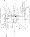
- Figs. 1 to 5 are views showing a first embodiment (viz., concrete embodiment) of a drive device for an electric vehicle, according to the present invention, in which Fig. 1 schematically shows a layout of a power motor unit used as the drive device in a motor room of the electric vehicle of the front wheel drive type, Fig. 2 is a plan view of Fig. 1 , Fig. 2 is a side view of Fig. 1 , and Fig. 3 is a front view taken from a front position of Fig. 1 .
- paired left and right side members 2 which extend in parallel with each other toward a front position of the vehicle body to serve as skeleton reinforcing members of the motor room 1, and as is seen from Fig. 2 , below the paired left and right side members 2, there are arranged a pair of suspension members 3 and 4 which are provided at front and rear positions respectively.
- These paired front and rear suspension members 3 and 4 are connected through a pair of reinforcing members 5 that extend in a vehicle body longitudinal direction like cross-linked members, and the front and rear suspension members are connected to and supported by the left and right side members 5 through for example four insulators 6.
- the suspension member 4 has left and right portions to which respective transverse links 7 are connected, and by the transverse links 7, there are supported left and right road wheels (front road wheels) 8 through axle shafts (not shown).
- the motor power unit 9 is constructed to have both a motor or prime mover as a generator-motor (for example, a three-phase synchronous motor of a type that has permanent magnets embedded and serves as a generator during regeneration) 11 and a speed reduction gear unit 12 including a final drive unit (viz., final drive gear).
- a generator-motor for example, a three-phase synchronous motor of a type that has permanent magnets embedded and serves as a generator during regeneration
- a speed reduction gear unit 12 including a final drive unit (viz., final drive gear).
- an integral unit including the motor and speed reduction gear unit is mounted on the paired front and rear suspension members 3 and 4 in such a manner that the motor and the speed reduction gear unit are arranged in a vehicle body width direction, the integral unit being produced by integrally joining respective cases, which are a motor case 11a and a speed reduction gear case 12a, of the motor and speed reduction gear unit.
- An upper portion of the motor case 11a is fixed through an antivibration mount 13 as a first mount portion to an upper surface of one of the side members 2 as a first fixing position of a vehicle body side. Furthermore, a front portion of the speed reduction gear case 11a is fixed through an antivibration mount 14 as a second mount portion to an upper surface of the front suspension member 3 as a second fixing position of the vehicle body side, and a rear portion of the speed reduction gear case 12a is fixed through an antivibration mount 15 as a third mount portion to an upper surface of the rear suspension member 4 as a third fixing position of the vehicle body side. As is seen from Figs.
- the fixing position determined by the antivibration mount 14 as the second mount portion and the fixing position determined by the antivibration mount 15 as the third mount portion are positioned below the fixing position determined by the antivibration mount 13 as the first mount portion.
- the inverter 10 is supported through a stay 16 by the front suspension member 3 and the reinforcing member 5 while straddling the members 3 and 5.
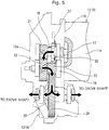
- Fig. 5 shows an internal construction of an essential part of the motor power unit 9.
- the motor 11 has a generally cylindrical motor case 11a, and the motor case has, at a side where a rotation shaft 17 of the motor extends, an end surface 11b that is to be mated with the speed reduction gear unit 12.
- the speed reduction gear unit 12 is so postured that an input shaft 18, an intermediate shaft 19 and a differential case 20 are arranged in the speed reduction gear case 12a in order in a downward direction.
- a rotation force of the rotation shaft 17 of the motor 11 there is mounted a speed reduction gear 21.
- the motor case 12a and the speed reduction gear case 13a are integrally joined using the end surface of the of the motor case 11a where the rotation shaft 17 extends as a contact surface so that the rotation shaft 17 of the motor 11 and the input shaft 18 of the speed reduction gear unit 12 are to be aligned. With such arrangement, the motor power unit 9 is produced.
- a speed reduction gear 22 meshed with a speed reduction gear 21 mounted on the input shaft 18.
- another speed reduction gear 23 is mounted on the intermediate shaft 19.
- a differential gear 24 is integrally mounted on a differential gear 24 as a final gear, and the differential gear 24 is meshed with the speed reduction gear 23 on the intermediate shaft 19.
- a pair of side gears (not shown) and a pair of pinion mate gears (not shown) meshed with the paired side gears, and rotation output of the side gears produces the rotation output of the speed reduction gear unit 12.
- Fig. 1 the drive shafts 25 are not shown for avoiding complication of the drawing.
- Denoted by numeral 26 is a parking lock gear that is coaxial with the speed reduction gear 21, and the parking lock gear 26 and a lock tooth 27 engageable with the parking lock gear 26 constitute a parking lock mechanism.
- a steering linkage 28 of the power steering device As is seen from Figs. 2 and 3 , behind the drive shafts 25, there is arranged a steering linkage 28 of the power steering device.
- the steering linkage 28 extends in a vehicle body width direction below the antivibration mount 15 as the third mount portion, and thus, interference with the antivibration mount 15 is avoided.
- the posture of the unit 9 is so made that an upper portion of the speed reduction gear case 12a that contains the motor 11 placed at a lower part of the speed reduction gear case 12a takes a position at a front side of the vehicle body causing the motor power unit 9 to incline forward.
- the rotation shaft 17 of the motor 11 is positioned above the rotation center of the differential gear 24 in the speed reduction gear case 12a and at the same time, the rotation shaft 17 of the motor 11 is positioned at the more front side of the vehicle body than the rotation center of the differential gear 24.
- the motor power unit 9 including the motor 11 and the speed reduction gear unit 12 is arranged within a diameter of the road wheel 8 as is understood from the plan view, side view and front view of the vehicle body.
- the speed reduction gear unit 12 including the differential gear 24 in the motor power unit 9 is placed on a center line L1 together with the antivibration mount 14 as the second mount portion and the antivibration mount 15 as the third mount portion, the center line L1 being a line through which the vehicle width (tread) is bisected.
- the motor 11 and inverter 10 are arranged to put therebetween the speed reduction gear unit 12 placing the motor 11 at one vehicle body width side and the inverter 10 at the other vehicle body width side.
- the left and right drive shafts 25 each extending from the differential case 20 to the road wheel 8 have generally the same length.
- centers of the antivibration mounts 14 and 15 as the second and third mount portions of the motor power unit 9 are placed on a horizontal axis line L2 that extends through the rotation center of the differential gear 24.
- the motor 11 since, in the construction of the motor power unit 9 in which the motor 11 and the speed reduction gear unit 12 are integrally joined to each other, the motor 11 is placed above the differential gear 24 in the speed reduction gear case 12a, the length of the motor power unit 9 in the vehicle body longitudinal direction is reduced and thus mounting of the unit 9 into the motor room 1 brings about a spacial advantage.
- the motor 11 and inverter 10 are arranged to put therebetween the speed reduction gear unit 12 placing the motor 11 at one vehicle body lateral side and the inverter 10 at the other vehicle body lateral side, and thus, the spacial advantage is obtained by such arrangement. Furthermore, weight-balanced arrangement in the left and right is established, which is another advantage.
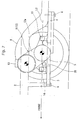
- Figs. 6 and 7 show a second embodiment of the present invention, in which parts and portions that are the same as those of Figs. 2 and 3 are denoted by the same numerals.
- the steering linkage 28 is placed at the more front side than the drive shaft 25, which is only one difference. Also in this case, since the steering linkage 28 is arranged to extend under the antivibration mount 14 as the second mount portion in the vehicle body width direction, interference with the antivibration mount 14 is avoided.
Landscapes
- Engineering & Computer Science (AREA)
- Transportation (AREA)
- Mechanical Engineering (AREA)
- Chemical & Material Sciences (AREA)
- Combustion & Propulsion (AREA)
- Power Engineering (AREA)
- Arrangement Or Mounting Of Propulsion Units For Vehicles (AREA)
- Hybrid Electric Vehicles (AREA)
- Electric Propulsion And Braking For Vehicles (AREA)
- Arrangement Of Transmissions (AREA)
- Connection Of Motors, Electrical Generators, Mechanical Devices, And The Like (AREA)
Abstract
A motor power unit (9) is installed in a motor room (1). The motor power unit (9) is produced by integrally joining a motor (11) and a speed reduction gear unit (12) using, as a joining surface, one end surface of a motor case (11a) where a rotation shaft is provided, the speed reduction gear unit (12) including a speed reduction gear case (12a) in which a differential gear is installed together with a speed reduction gear. The motor (11) is placed above the differential gear installed in the speed reduction gear case (12a). The rotation shaft of the motor (11) is placed at the more front side of a vehicle body than a rotation center of the differential gear. With such arrangement, the length of the motor power unit (9) in a vehicle body longitudinal direction can be reduced.
Description
- The present invention relates to a drive device as a power unit of an electric vehicle.
- In electric vehicles of a front wheel drive type that employs an electric motor as a prime mover, there is a type in which, as is described in Patent Document-1, a motor power unit assembled by integrally joining a motor and a speed reduction gear unit is arranged in a motor room that corresponds to an engine room of a gasoline engine vehicle. Since, in the speed reduction gear unit, a differential gear is installed as a final gear that distributes a rotation force of the motor to right and left drive road wheels while reducing the rotation speed, the motor power unit is so set in the motor room that the motor and the speed reduction gear unit are arranged abreast in a vehicle body width direction causing a rotation center of the differential gear to be directed to the vehicle body width direction. In the motor room, an inverter and a converter are also set together with the motor power unit.
- However, the known motor power unit described in Patent Document-1 is large in size particularly in size in the vehicle body longitudinal direction, and thus, mounting the unit into the motor room requires a larger occupying space thereby not only lowering the space efficiency of the motor room but also restricting the layout for the other mounted devices.
- Patent Document-1 :
Japanese Laid-open Patent Application (tokkai) 2011-20624 - The present invention is provided by taking the above-mentioned problem into consideration and aims to provide a drive device in which the length of the motor power unit in the vehicle body longitudinal direction is reduced for increasing the space efficiency of the motor room and suppressing the restriction of the layout for the other mounted devices.
- In accordance with the present invention, there is provided, in an electric vehicle including a generator-motor that drives road wheels to rotate the same and generates electricity by receiving rotation of the road wheels and a differential gear that distributes a rotation force of the generator-motor to left and right road wheels, an arrangement in which when the power motor unit is mounted on the vehicle, the generator-motor takes a position above the differential gear.
- In accordance with the present invention, since the generator-motor is placed above the differential gear, the length of the motor power unit in the vehicle body longitudinal direction is reduced. Thus, the occupying space for the unit in the motor room is reduced and thus the space efficiency is increased and the restriction of the layout for the other mounted devices in the motor room is suppressed.
-
-
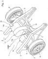
Fig. 1 is a view of a first embodiment of a drive device for an electric vehicle according to the present invention, which is a schematically illustrated explanation drawing of a motor room; -
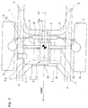
Fig. 2 is a plan view ofFig. 1 ; -
Fig. 3 is a side view ofFig. 1 ; -
Fig. 4 is a front view ofFig. 1 ; -
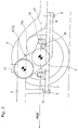
Fig. 5 is an internal construction view of a speed reduction gear unit employed in a motor power unit shown inFig. 1 ; -
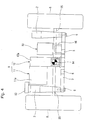
Fig. 6 is a view of a second embodiment of the drive device for the electric vehicle according to the present invention, which is a plan view likeFig. 2 ; and -
Fig. 7 is a side view ofFig. 6 . -
Figs. 1 to 5 are views showing a first embodiment (viz., concrete embodiment) of a drive device for an electric vehicle, according to the present invention, in whichFig. 1 schematically shows a layout of a power motor unit used as the drive device in a motor room of the electric vehicle of the front wheel drive type,Fig. 2 is a plan view ofFig. 1 ,Fig. 2 is a side view ofFig. 1 , andFig. 3 is a front view taken from a front position ofFig. 1 . - As is shown in
Figs. 1 and2 to 4 , within amotor room 1 provided at a front portion of a vehicle body, there are arranged paired left andright side members 2 which extend in parallel with each other toward a front position of the vehicle body to serve as skeleton reinforcing members of themotor room 1, and as is seen fromFig. 2 , below the paired left andright side members 2, there are arranged a pair ofsuspension members rear suspension members members 5 that extend in a vehicle body longitudinal direction like cross-linked members, and the front and rear suspension members are connected to and supported by the left andright side members 5 through for example fourinsulators 6. Thesuspension member 4 has left and right portions to which respectivetransverse links 7 are connected, and by thetransverse links 7, there are supported left and right road wheels (front road wheels) 8 through axle shafts (not shown). - Onto the paired front and
rear suspension members motor power unit 9 and aninverter 10 that controls driving of themotor power unit 9. As will be described hereinafter, themotor power unit 9 is constructed to have both a motor or prime mover as a generator-motor (for example, a three-phase synchronous motor of a type that has permanent magnets embedded and serves as a generator during regeneration) 11 and a speedreduction gear unit 12 including a final drive unit (viz., final drive gear). Upon mounting, an integral unit including the motor and speed reduction gear unit is mounted on the paired front andrear suspension members motor case 11a and a speedreduction gear case 12a, of the motor and speed reduction gear unit. - An upper portion of the
motor case 11a is fixed through anantivibration mount 13 as a first mount portion to an upper surface of one of theside members 2 as a first fixing position of a vehicle body side. Furthermore, a front portion of the speedreduction gear case 11a is fixed through anantivibration mount 14 as a second mount portion to an upper surface of thefront suspension member 3 as a second fixing position of the vehicle body side, and a rear portion of the speedreduction gear case 12a is fixed through anantivibration mount 15 as a third mount portion to an upper surface of therear suspension member 4 as a third fixing position of the vehicle body side. As is seen fromFigs. 1 ,3 and4 , the fixing position determined by theantivibration mount 14 as the second mount portion and the fixing position determined by theantivibration mount 15 as the third mount portion are positioned below the fixing position determined by theantivibration mount 13 as the first mount portion. - As is seen from
Fig. 4 , theinverter 10 is supported through astay 16 by thefront suspension member 3 and the reinforcingmember 5 while straddling themembers -
Fig. 5 shows an internal construction of an essential part of themotor power unit 9. As shown, themotor 11 has a generallycylindrical motor case 11a, and the motor case has, at a side where arotation shaft 17 of the motor extends, anend surface 11b that is to be mated with the speedreduction gear unit 12. While, the speedreduction gear unit 12 is so postured that aninput shaft 18, anintermediate shaft 19 and adifferential case 20 are arranged in the speedreduction gear case 12a in order in a downward direction. Into theinput shaft 18, there is directly inputted a rotation force of therotation shaft 17 of themotor 11, and on theinput shaft 17, there is mounted aspeed reduction gear 21. Thus, themotor case 12a and the speed reduction gear case 13a are integrally joined using the end surface of the of themotor case 11a where therotation shaft 17 extends as a contact surface so that therotation shaft 17 of themotor 11 and theinput shaft 18 of the speedreduction gear unit 12 are to be aligned. With such arrangement, themotor power unit 9 is produced. - Onto the
intermediate shaft 19 in the speedreduction gear case 12a, there is mounted aspeed reduction gear 22 meshed with aspeed reduction gear 21 mounted on theinput shaft 18. In addition to thegear 22, anotherspeed reduction gear 23 is mounted on theintermediate shaft 19. On a peripheral portion of thedifferential case 20, there is integrally mounted adifferential gear 24 as a final gear, and thedifferential gear 24 is meshed with thespeed reduction gear 23 on theintermediate shaft 19. Furthermore, within thedifferential case 20, there are installed a pair of side gears (not shown) and a pair of pinion mate gears (not shown) meshed with the paired side gears, and rotation output of the side gears produces the rotation output of the speedreduction gear unit 12. That is, within the speedreduction gear case 12a of the speedreduction gear unit 12, there are installed thedifferential case 20 and thedifferential gear 24 together with the plurality ofspeed reduction gears Figs. 2 and3 , to the side gears installed in thedifferential case 20, there are connecteddrive shafts 25 for driving the left and rightdrive road wheels 8. - In
Fig. 1 , thedrive shafts 25 are not shown for avoiding complication of the drawing. Denoted bynumeral 26 is a parking lock gear that is coaxial with thespeed reduction gear 21, and theparking lock gear 26 and alock tooth 27 engageable with theparking lock gear 26 constitute a parking lock mechanism. - As is seen from
Figs. 2 and3 , behind thedrive shafts 25, there is arranged asteering linkage 28 of the power steering device. Thesteering linkage 28 extends in a vehicle body width direction below theantivibration mount 15 as the third mount portion, and thus, interference with theantivibration mount 15 is avoided. - When the
motor power unit 9 is mounted on the vehicle body in the above-mentioned manner, the posture of theunit 9 is so made that an upper portion of the speedreduction gear case 12a that contains themotor 11 placed at a lower part of the speedreduction gear case 12a takes a position at a front side of the vehicle body causing themotor power unit 9 to incline forward. With this inclined arrangement, therotation shaft 17 of themotor 11 is positioned above the rotation center of thedifferential gear 24 in the speedreduction gear case 12a and at the same time, therotation shaft 17 of themotor 11 is positioned at the more front side of the vehicle body than the rotation center of thedifferential gear 24. - Furthermore, as is seen from
Figs. 2 to 4 , themotor power unit 9 including themotor 11 and the speedreduction gear unit 12 is arranged within a diameter of theroad wheel 8 as is understood from the plan view, side view and front view of the vehicle body. - Furthermore, as is seen from
Figs. 1 ,2 and4 , the speedreduction gear unit 12 including thedifferential gear 24 in themotor power unit 9 is placed on a center line L1 together with theantivibration mount 14 as the second mount portion and theantivibration mount 15 as the third mount portion, the center line L1 being a line through which the vehicle width (tread) is bisected. - As a result, as is seen from the drawings, when the position of the speed
reduction gear unit 12 including thedifferential gear 24 in themotor power unit 9 is considered as a reference position, themotor 11 andinverter 10 are arranged to put therebetween the speedreduction gear unit 12 placing themotor 11 at one vehicle body width side and theinverter 10 at the other vehicle body width side. The left andright drive shafts 25 each extending from thedifferential case 20 to theroad wheel 8 have generally the same length. - As is seen from
Fig. 3 , centers of theantivibration mounts motor power unit 9 are placed on a horizontal axis line L2 that extends through the rotation center of thedifferential gear 24. - Accordingly, in the embodiment, since, in the construction of the
motor power unit 9 in which themotor 11 and the speedreduction gear unit 12 are integrally joined to each other, themotor 11 is placed above thedifferential gear 24 in the speedreduction gear case 12a, the length of themotor power unit 9 in the vehicle body longitudinal direction is reduced and thus mounting of theunit 9 into themotor room 1 brings about a spacial advantage. - Furthermore, as has been mentioned hereinabove, when the position of the speed
reduction gear unit 12 including thedifferential gear 24 in themotor power unit 9 is considered as a reference position, themotor 11 andinverter 10 are arranged to put therebetween the speedreduction gear unit 12 placing themotor 11 at one vehicle body lateral side and theinverter 10 at the other vehicle body lateral side, and thus, the spacial advantage is obtained by such arrangement. Furthermore, weight-balanced arrangement in the left and right is established, which is another advantage. - Furthermore, since the
rotation shaft 17 of themotor 11 is placed at the more front side of the vehicle body than the rotation center of thedifferential gear 24 in the speedreduction gear case 12a, rash of themotor 11 into the vehicle cabin, which would occur in a vehicle collision, is suppressed. This is an advantageous safety measure against vehicle collisions. -
Figs. 6 and7 show a second embodiment of the present invention, in which parts and portions that are the same as those ofFigs. 2 and3 are denoted by the same numerals. As will be clearly understood when comparingFigs. 6 and7 withFigs. 2 and3 , in the second embodiment shown byFigs. 6 and7 , thesteering linkage 28 is placed at the more front side than thedrive shaft 25, which is only one difference. Also in this case, since thesteering linkage 28 is arranged to extend under theantivibration mount 14 as the second mount portion in the vehicle body width direction, interference with theantivibration mount 14 is avoided. - Also in this second embodiment, substantial same effects as those of the first embodiment are obtained.
Claims (20)
- A drive device for an electric vehicle, comprising:a generator-motor that drives left and right road wheels to rotate the same and generates electricity by receiving rotation of the road wheels; anda differential gear that distributes a rotation force of the generator-motor to the left and right road wheels,wherein when the drive device is mounted on the vehicle, the generator-motor takes a position above the differential gear.
- A drive device for an electric vehicle as claimed in Claim 1, in which:an inverter is provided for operating the generator-motor, andwhen the vehicle is shown in a plan view, the generator-motor and the inverter are arranged to put therebetween the differential gear placing the generator-motor at one vehicle body lateral side and the inverter at the other vehicle body lateral side.
- A drive device for an electric vehicle as claimed in Claim 2, in which:when the vehicle is shown in a plan view, the differential gear is placed at a generally middle position of a width of the vehicle body, and the generator-motor and the inverter are placed at both sides of the differential gear.
- A drive device for an electric vehicle as claimed in Claim 1, in which:the differential gear is installed in a speed reduction gear case together with speed reduction elements thereby to constitute a speed reduction gear unit, andthe speed reduction gear unit and the generator-motor are integrally joined to each other.
- A drive device for an electric vehicle as claimed in Claim 1, in which:when the vehicle is shown in a plan view, the generator-motor and the differential gear are arranged to be received within a diameter of each road wheel.
- A drive device for an electric vehicle as claimed in Claim 5, in which:the generator-motor is so arranged that a rotation shaft of the generator-motor is placed at the more front side of the vehicle body than a rotation center of the differential gear.
- A drive device for an electric vehicle as claimed in Claim 1, in which:the differential gear is installed in a speed reduction gear case together with speed reduction elements thereby to constitute a speed reduction gear unit;the speed reduction gear unit and the generator-motor are integrally joined to each other; anda first mount portion is provided through which the generator-motor is fixed to a first fixing position of the vehicle body; anda second mount portion is provided through which the speed reduction gear unit is fixed to a second fixing position of the vehicle body.
- A drive device for an electric vehicle as claimed in Claim 7, in which:a third mount portion is provided through which the speed reduction gear unit is fixed to a third fixing position of the vehicle body.
- A drive device for an electric vehicle as claimed in Claim 8, in which:the second and third fixing positions in the first to third fixing positions defined by the corresponding mount portions are set at positions that are below the first fixing position.
- A drive device for an electric vehicle, comprising:a generator-motor that drives left and right road wheels to rotate the same and generates electricity by receiving rotation of the road wheels;a differential gear that distributes a rotation force of the generator-motor to the left and right road wheels; anda speed reduction gear unit that includes a speed reduction gear case in which the differential gear is installed together with speed reduction elements,wherein the generator-motor and the differential gear are integrally joined to each other in such a manner that when the drive device is mounted on the vehicle, the generator-motor is placed above the differential gear.
- A drive device for an electric vehicle as claimed in Claim 10, in which:a first mount portion is provided through which the generator-motor is fixed to a first fixing position of the vehicle body; anda second mount portion is provided through which the speed reduction gear unit is fixed to a second fixing position of the vehicle body.
- A drive device for an electric vehicle as claimed in Claim 11, in which:a third mount portion is provided through which the speed reduction gear unit is fixed to a third fixing position of the vehicle body.
- A drive device for an electric vehicle as claimed in Claim 12, in which:the second and third fixing positions in the first to third fixing positions defined by the corresponding mount portions are set at positions that are below the first fixing position.
- A drive device for an electric vehicle as claimed in Claim 11, in which:when the vehicle is shown in a plan view, the generator-motor and the differential gear are arranged to be received within a diameter of each road wheel.
- A drive device for an electric vehicle as claimed in Claim 14, in which:the generator-motor is so arranged that a rotation shaft of the generator-motor is placed at the more front side of the vehicle body than a rotation center of the differential gear.
- A drive device for an electric vehicle as claimed in Claim 10, in which:an inverter is provided for operating the generator-motor, andwhen the vehicle is shown in a plan view, the differential gear is arranged at a generally middle of a width of the vehicle body and the generator-motor and the inverter are arranged to put therebetween the differential gear placing the generator-motor at one vehicle body lateral side and the inverter at the other vehicle body lateral side.
- A drive device for an electric vehicle, comprising:a generator-motor that drives left and right road wheels to rotate the same and generates electricity by receiving rotation of the road wheels;a differential gear that distributes a rotation force of the generator-motor to the left and right road wheels;an inverter for operating the generator-motor; anda speed reduction gear unit including a speed reduction gear case in which the differential gear is installed together with speed reduction elements, the speed reduction gear unit being so oriented that a rotation center of the differential gear is directed to a vehicle body width direction,wherein the generator-motor and the inverter are arranged to put therebetween the speed reduction gear unit placing the generator-motor at one vehicle body lateral side and the inverter at the other vehicle body lateral side, and the generator-motor and the speed reduction gear unit are integrally joined to each other in such a manner that when the drive device is mounted on the vehicle, the generator-motor is placed above the differential gear.
- A drive device for an electric vehicle as claimed in Claim 17, in which:the generator-motor is so arranged that a rotation shaft of the generator-motor is placed at the more front side of the vehicle body that a rotation center of the differential gear.
- A drive device for an electric vehicle as claimed in Claim 18, in which:a first mount portion is provided through which the generator-motor is fixed to a first fixing position of the vehicle body;a second mount portion is provided through which the speed reduction gear unit is fixed to a second fixing position of the vehicle body; anda third mount portion is provided through when the speed reduction gear unit is fixed to a third fixing position of the vehicle body.
- A drive device for an electric vehicle as claimed in Claim 19, in which:when the vehicle is shown in a plan view, the generator-motor and the speed reduction gear unit are arranged to be received within a diameter of each road wheel.
Applications Claiming Priority (2)
| Application Number | Priority Date | Filing Date | Title |
|---|---|---|---|
| JP2013054545 | 2013-03-18 | ||
| PCT/JP2014/057054 WO2014148410A1 (en) | 2013-03-18 | 2014-03-17 | Drive device for electric vehicle |
Publications (1)
| Publication Number | Publication Date |
|---|---|
| EP2977251A1 true EP2977251A1 (en) | 2016-01-27 |
Family
ID=51580089
Family Applications (1)
| Application Number | Title | Priority Date | Filing Date |
|---|---|---|---|
| EP14768950.9A Withdrawn EP2977251A1 (en) | 2013-03-18 | 2014-03-17 | Drive device for electric vehicle |
Country Status (5)
| Country | Link |
|---|---|
| US (1) | US20150375783A1 (en) |
| EP (1) | EP2977251A1 (en) |
| JP (1) | JPWO2014148410A1 (en) |
| CN (1) | CN105073464A (en) |
| WO (1) | WO2014148410A1 (en) |
Cited By (4)
| Publication number | Priority date | Publication date | Assignee | Title |
|---|---|---|---|---|
| WO2019094693A1 (en) * | 2017-11-10 | 2019-05-16 | Dana Heavy Vehicle Systems Group, Llc | Modular head assembly for an electric axle |
| EP3584103A4 (en) * | 2017-07-28 | 2020-12-23 | Daimler AG | DRIVE DEVICE FOR ELECTRIC TRUCKS |
| EP3858710A1 (en) * | 2020-01-29 | 2021-08-04 | McLaren Automotive Limited | Steering assistance |
| WO2024052478A1 (en) * | 2022-09-09 | 2024-03-14 | Trailer Dynamics Gmbh | Electric powertrain for a commercial vehicle with two electric motors |
Families Citing this family (17)
| Publication number | Priority date | Publication date | Assignee | Title |
|---|---|---|---|---|
| US9428040B2 (en) * | 2012-12-21 | 2016-08-30 | Honda Motor Co., Ltd. | Electric motor mounting structure |
| US9126581B2 (en) * | 2013-05-08 | 2015-09-08 | GM Global Technology Operations LLC | Hybrid powertrain and modular rear drive unit for same |
| US9573452B2 (en) * | 2014-04-07 | 2017-02-21 | Squaw-Fleet, LLC | Rear carriage structure for an electric vehicle |
| JP6850691B2 (en) | 2017-06-30 | 2021-03-31 | ダイムラー・アクチェンゲゼルシャフトDaimler AG | Vehicle drive |
| JP6793095B2 (en) * | 2017-06-30 | 2020-12-02 | ダイムラー・アクチェンゲゼルシャフトDaimler AG | Vehicle drive |
| US11007857B2 (en) | 2017-08-31 | 2021-05-18 | Daimler Ag | Vehicle driving apparatus |
| JP6955433B2 (en) | 2017-12-19 | 2021-10-27 | ダイムラー・アクチェンゲゼルシャフトDaimler AG | Battery housing |
| JP6964509B2 (en) * | 2017-12-22 | 2021-11-10 | 株式会社アイシン | Vehicle drive |
| JP7285684B2 (en) | 2019-05-07 | 2023-06-02 | ダイハツ工業株式会社 | Power unit suspension structure |
| JP7448114B2 (en) * | 2019-08-09 | 2024-03-12 | メルセデス・ベンツ グループ アクチェンゲゼルシャフト | Vehicle control device |
| GB2590382B (en) * | 2019-12-13 | 2022-04-06 | Dyson Technology Ltd | Electric drive unit |
| JP7395814B2 (en) | 2019-12-19 | 2023-12-12 | メルセデス・ベンツ グループ アクチェンゲゼルシャフト | Vehicle drive system |
| US11420514B2 (en) * | 2020-07-14 | 2022-08-23 | Allison Transmission, Inc. | Multispeed transaxle with sprung powertrain mounting and methods therefor |
| JP7535020B2 (en) | 2021-07-29 | 2024-08-15 | ダイムラー トラック エージー | Electric vehicles |
| JPWO2025004150A1 (en) * | 2023-06-26 | 2025-01-02 | ||
| EP4527654A1 (en) * | 2023-09-25 | 2025-03-26 | Scania CV AB | Electric drive axle arrangement and vehicle comprising the electric drive axle arrangement |
| CN220904668U (en) * | 2023-10-31 | 2024-05-07 | 比亚迪股份有限公司 | Drive unit and vehicle |
Family Cites Families (21)
| Publication number | Priority date | Publication date | Assignee | Title |
|---|---|---|---|---|
| JPS4721308U (en) * | 1971-03-15 | 1972-11-10 | ||
| US4216839A (en) * | 1978-07-20 | 1980-08-12 | Unique Mobility Inc. | Electrically powered motor vehicle |
| US6598691B2 (en) * | 1997-12-18 | 2003-07-29 | Honda Giken Kogyo Kabushiki Kaisha | Electric vehicle |
| JP2003072392A (en) * | 2001-08-31 | 2003-03-12 | Honda Motor Co Ltd | Electric motor structure of electric vehicle |
| US7416039B1 (en) * | 2002-09-20 | 2008-08-26 | Anderson Donald C | Regenerative self propelled vehicles |
| DE602004024325D1 (en) * | 2003-09-29 | 2010-01-07 | Nissan Motor | DRIVE MOTOR MOUNTING CONSTRUCTION AND FASTENING METHOD |
| JP3987833B2 (en) * | 2004-02-27 | 2007-10-10 | 株式会社日立製作所 | Vehicle drive device |
| JP4930576B2 (en) * | 2009-02-27 | 2012-05-16 | 日産自動車株式会社 | Motor support structure |
| EP2419291B1 (en) * | 2009-04-15 | 2014-09-10 | Nissan Motor Co., Ltd. | Vehicle component mounting arrangement |
| JP5018837B2 (en) | 2009-07-17 | 2012-09-05 | 日産自動車株式会社 | Electric vehicle mounting structure |
| EP2419287B1 (en) * | 2009-04-15 | 2014-05-07 | Nissan Motor Co., Ltd. | Vehicle component mounting structure |
| JP5211002B2 (en) * | 2009-09-15 | 2013-06-12 | 日立オートモティブシステムズ株式会社 | Drive control device |
| JP5532877B2 (en) * | 2009-12-03 | 2014-06-25 | マツダ株式会社 | Vehicle battery arrangement structure |
| US8479858B2 (en) * | 2009-12-03 | 2013-07-09 | Mazda Motor Corporation | Battery arrangement structure of vehicle |
| FR2954232B1 (en) * | 2009-12-22 | 2012-04-20 | Peugeot Citroen Automobiles Sa | MOTOR VEHICLE COMPRISING AN ELECTROMOTIVE UNIT AND ITS POWER SUPPLY MODULE ARRANGED AT THE NEIGHBORHOOD OF A VEHICLE RUNNING TRAIN |
| JP5630613B2 (en) * | 2010-12-28 | 2014-11-26 | スズキ株式会社 | Motor mount structure for electric vehicles |
| JP5561156B2 (en) * | 2010-12-28 | 2014-07-30 | マツダ株式会社 | Electric vehicle |
| JP5494499B2 (en) * | 2011-01-12 | 2014-05-14 | マツダ株式会社 | Electric vehicle |
| JP5800214B2 (en) * | 2011-02-23 | 2015-10-28 | スズキ株式会社 | Electric vehicle power unit suspension structure |
| JP2012224280A (en) * | 2011-04-21 | 2012-11-15 | Honda Motor Co Ltd | Electric power steering system |
| JP5900012B2 (en) * | 2012-02-24 | 2016-04-06 | 日産自動車株式会社 | Powertrain structure for electric vehicles |
-
2014
- 2014-03-17 JP JP2015506755A patent/JPWO2014148410A1/en active Pending
- 2014-03-17 US US14/769,063 patent/US20150375783A1/en not_active Abandoned
- 2014-03-17 EP EP14768950.9A patent/EP2977251A1/en not_active Withdrawn
- 2014-03-17 WO PCT/JP2014/057054 patent/WO2014148410A1/en not_active Ceased
- 2014-03-17 CN CN201480010645.1A patent/CN105073464A/en active Pending
Non-Patent Citations (1)
| Title |
|---|
| See references of WO2014148410A1 * |
Cited By (6)
| Publication number | Priority date | Publication date | Assignee | Title |
|---|---|---|---|---|
| EP3584103A4 (en) * | 2017-07-28 | 2020-12-23 | Daimler AG | DRIVE DEVICE FOR ELECTRIC TRUCKS |
| WO2019094693A1 (en) * | 2017-11-10 | 2019-05-16 | Dana Heavy Vehicle Systems Group, Llc | Modular head assembly for an electric axle |
| CN111344172A (en) * | 2017-11-10 | 2020-06-26 | 德纳重型车辆系统集团有限责任公司 | Modular head assemblies for electric axles |
| US11338660B2 (en) | 2017-11-10 | 2022-05-24 | Dana Heavy Vehicle Systems Group, Llc | Modular head assembly for an electric axle |
| EP3858710A1 (en) * | 2020-01-29 | 2021-08-04 | McLaren Automotive Limited | Steering assistance |
| WO2024052478A1 (en) * | 2022-09-09 | 2024-03-14 | Trailer Dynamics Gmbh | Electric powertrain for a commercial vehicle with two electric motors |
Also Published As
| Publication number | Publication date |
|---|---|
| CN105073464A (en) | 2015-11-18 |
| US20150375783A1 (en) | 2015-12-31 |
| WO2014148410A1 (en) | 2014-09-25 |
| JPWO2014148410A1 (en) | 2017-02-16 |
Similar Documents
| Publication | Publication Date | Title |
|---|---|---|
| US20150375783A1 (en) | Drive Device for Electric Vehicle | |
| KR101546582B1 (en) | Drive train of a motor vehicle which can be driven in a purely electric manner | |
| US9499205B1 (en) | Hybrid vehicle packaging system | |
| US9884545B1 (en) | Traction battery mounting assembly and securing method | |
| US9168818B2 (en) | Electric vehicle | |
| JP6279102B2 (en) | Integrated steering drive shaft and electric vehicle for automobile | |
| US9630482B2 (en) | System for driving the drive wheels of an electric or hybrid vehicle | |
| KR20120137291A (en) | Motor vehicle having a drive train which has a laterally arranged internal combustion engine | |
| KR101884391B1 (en) | 4wd electric vehicle, method of converting 4wd vehicle into 4wd electric vehicle and 4wd electric vehicle converting kit | |
| JP5900012B2 (en) | Powertrain structure for electric vehicles | |
| US11667180B2 (en) | Cover for an electric axle assembly | |
| JPWO2019082258A1 (en) | Power transmission device for four-wheel drive vehicle | |
| CN104085298A (en) | Positive differential type electromechanical composite transmission device | |
| CN203766478U (en) | Hybrid power system and automobile with hybrid power system | |
| EP4079552B1 (en) | Vehicle drive apparatus | |
| US20200298700A1 (en) | Power transmission device for four wheel drive vehicle | |
| JP2019189171A (en) | Drive unit support device | |
| CN104129284A (en) | Positive differential type electro-mechanical composite transmission device | |
| CN114379354B (en) | Vehicle with a vehicle body having a vehicle body support | |
| CN104442343A (en) | Electric vehicle battery attachment assembly and method | |
| WO2019082256A1 (en) | Power transmission device for four-wheel drive vehicle | |
| EP3118045B1 (en) | Electric vehicle | |
| JP2014019336A (en) | Vehicle drive device | |
| JP3884421B2 (en) | VEHICLE POWER TRANSMISSION DEVICE AND VEHICLE DRIVE ELECTRIC SYSTEM USING THE SAME | |
| KR102014356B1 (en) | In wheel type running gear |
Legal Events
| Date | Code | Title | Description |
|---|---|---|---|
| PUAI | Public reference made under article 153(3) epc to a published international application that has entered the european phase |
Free format text: ORIGINAL CODE: 0009012 |
|
| 17P | Request for examination filed |
Effective date: 20150727 |
|
| AK | Designated contracting states |
Kind code of ref document: A1 Designated state(s): AL AT BE BG CH CY CZ DE DK EE ES FI FR GB GR HR HU IE IS IT LI LT LU LV MC MK MT NL NO PL PT RO RS SE SI SK SM TR |
|
| AX | Request for extension of the european patent |
Extension state: BA ME |
|
| DAX | Request for extension of the european patent (deleted) | ||
| STAA | Information on the status of an ep patent application or granted ep patent |
Free format text: STATUS: THE APPLICATION HAS BEEN WITHDRAWN |
|
| 18W | Application withdrawn |
Effective date: 20161026 |