EP4079552B1 - Vehicle drive apparatus - Google Patents
Vehicle drive apparatus Download PDFInfo
- Publication number
- EP4079552B1 EP4079552B1 EP20902567.5A EP20902567A EP4079552B1 EP 4079552 B1 EP4079552 B1 EP 4079552B1 EP 20902567 A EP20902567 A EP 20902567A EP 4079552 B1 EP4079552 B1 EP 4079552B1
- Authority
- EP
- European Patent Office
- Prior art keywords
- vehicle
- couplers
- side support
- drive unit
- motor
- Prior art date
- Legal status (The legal status is an assumption and is not a legal conclusion. Google has not performed a legal analysis and makes no representation as to the accuracy of the status listed.)
- Active
Links
Images


Classifications
-
- B—PERFORMING OPERATIONS; TRANSPORTING
- B60—VEHICLES IN GENERAL
- B60K—ARRANGEMENT OR MOUNTING OF PROPULSION UNITS OR OF TRANSMISSIONS IN VEHICLES; ARRANGEMENT OR MOUNTING OF PLURAL DIVERSE PRIME-MOVERS IN VEHICLES; AUXILIARY DRIVES FOR VEHICLES; INSTRUMENTATION OR DASHBOARDS FOR VEHICLES; ARRANGEMENTS IN CONNECTION WITH COOLING, AIR INTAKE, GAS EXHAUST OR FUEL SUPPLY OF PROPULSION UNITS IN VEHICLES
- B60K1/00—Arrangement or mounting of electrical propulsion units
-
- B—PERFORMING OPERATIONS; TRANSPORTING
- B60—VEHICLES IN GENERAL
- B60K—ARRANGEMENT OR MOUNTING OF PROPULSION UNITS OR OF TRANSMISSIONS IN VEHICLES; ARRANGEMENT OR MOUNTING OF PLURAL DIVERSE PRIME-MOVERS IN VEHICLES; AUXILIARY DRIVES FOR VEHICLES; INSTRUMENTATION OR DASHBOARDS FOR VEHICLES; ARRANGEMENTS IN CONNECTION WITH COOLING, AIR INTAKE, GAS EXHAUST OR FUEL SUPPLY OF PROPULSION UNITS IN VEHICLES
- B60K17/00—Arrangement or mounting of transmissions in vehicles
- B60K17/04—Arrangement or mounting of transmissions in vehicles characterised by arrangement, location or kind of gearing
- B60K17/16—Arrangement or mounting of transmissions in vehicles characterised by arrangement, location or kind of gearing of differential gearing
-
- B—PERFORMING OPERATIONS; TRANSPORTING
- B60—VEHICLES IN GENERAL
- B60K—ARRANGEMENT OR MOUNTING OF PROPULSION UNITS OR OF TRANSMISSIONS IN VEHICLES; ARRANGEMENT OR MOUNTING OF PLURAL DIVERSE PRIME-MOVERS IN VEHICLES; AUXILIARY DRIVES FOR VEHICLES; INSTRUMENTATION OR DASHBOARDS FOR VEHICLES; ARRANGEMENTS IN CONNECTION WITH COOLING, AIR INTAKE, GAS EXHAUST OR FUEL SUPPLY OF PROPULSION UNITS IN VEHICLES
- B60K5/00—Arrangement or mounting of internal-combustion or jet-propulsion units
- B60K5/12—Arrangement of engine supports
- B60K5/1208—Resilient supports
- B60K5/1216—Resilient supports characterised by the location of the supports relative to the motor or to each other
-
- B—PERFORMING OPERATIONS; TRANSPORTING
- B60—VEHICLES IN GENERAL
- B60K—ARRANGEMENT OR MOUNTING OF PROPULSION UNITS OR OF TRANSMISSIONS IN VEHICLES; ARRANGEMENT OR MOUNTING OF PLURAL DIVERSE PRIME-MOVERS IN VEHICLES; AUXILIARY DRIVES FOR VEHICLES; INSTRUMENTATION OR DASHBOARDS FOR VEHICLES; ARRANGEMENTS IN CONNECTION WITH COOLING, AIR INTAKE, GAS EXHAUST OR FUEL SUPPLY OF PROPULSION UNITS IN VEHICLES
- B60K1/00—Arrangement or mounting of electrical propulsion units
- B60K2001/001—Arrangement or mounting of electrical propulsion units one motor mounted on a propulsion axle for rotating right and left wheels of this axle
-
- B—PERFORMING OPERATIONS; TRANSPORTING
- B60—VEHICLES IN GENERAL
- B60Y—INDEXING SCHEME RELATING TO ASPECTS CROSS-CUTTING VEHICLE TECHNOLOGY
- B60Y2200/00—Type of vehicle
- B60Y2200/10—Road Vehicles
- B60Y2200/14—Trucks; Load vehicles, Busses
-
- B—PERFORMING OPERATIONS; TRANSPORTING
- B60—VEHICLES IN GENERAL
- B60Y—INDEXING SCHEME RELATING TO ASPECTS CROSS-CUTTING VEHICLE TECHNOLOGY
- B60Y2200/00—Type of vehicle
- B60Y2200/10—Road Vehicles
- B60Y2200/14—Trucks; Load vehicles, Busses
- B60Y2200/142—Heavy duty trucks
-
- B—PERFORMING OPERATIONS; TRANSPORTING
- B60—VEHICLES IN GENERAL
- B60Y—INDEXING SCHEME RELATING TO ASPECTS CROSS-CUTTING VEHICLE TECHNOLOGY
- B60Y2200/00—Type of vehicle
- B60Y2200/90—Vehicles comprising electric prime movers
- B60Y2200/91—Electric vehicles
-
- B—PERFORMING OPERATIONS; TRANSPORTING
- B60—VEHICLES IN GENERAL
- B60Y—INDEXING SCHEME RELATING TO ASPECTS CROSS-CUTTING VEHICLE TECHNOLOGY
- B60Y2410/00—Constructional features of vehicle sub-units
- B60Y2410/10—Housings
Definitions
- the present invention relates to a vehicle drive apparatus according to the preamble of claim 1.
- Such electric vehicles each include a drive unit that includes, for example, a motor and a power transmission mechanism such as a speed reducer composed of a plurality of gears, and can transmit a driving force of the motor to a differential gear to which driving wheels are coupled.
- a drive unit that includes, for example, a motor and a power transmission mechanism such as a speed reducer composed of a plurality of gears, and can transmit a driving force of the motor to a differential gear to which driving wheels are coupled.
- JP 2019 189 171 A discloses a vehicle drive apparatus according to the preamble of claim 1 having a drive unit including a motor that generates a driving force in a vehicle with a ladder frame, a transmission that changes the driving force transmitted from the motor, and a differential that splits the driving force transmitted from the transmission and transmits the split forces to driving wheels of the vehicle, the vehicle drive apparatus further including: a drive unit housing at least partly housing the drive unit; a motor-side support coupling the drive unit housing to the ladder frame by two couplers arranged in a motor-side end region of the drive unit housing; and a differential-side support coupling the drive unit housing to the ladder frame in a differential-side end region of the drive unit housing.
- the drive unit When such a drive unit is mounted on an electric vehicle such as a commercial vehicle, the drive unit is supported by a ladder frame and a cross member.
- a vehicle drive apparatus such as a bracket needs to have higher reliability, which may lead to increase in size and weight of a support device.
- the drive unit itself has a size and a weight that are larger than those of the passenger cars.
- a larger moment is produced in the drive unit during vehicle is rolling or pitching.
- the stability of the drive unit during vehicle rolling or pitching needs to be improved.
- the present invention has been achieved to solve at least some of such problems, and it is an object thereof to provide a vehicle drive apparatus capable of improving the stability of a drive unit during vehicle rolling or the like while reducing the risk of increase in size and weight of a support device.
- a vehicle drive apparatus includes a drive unit including a motor that generates a driving force in a vehicle with a ladder frame, a transmission that changes the driving force transmitted from the motor, and a differential that splits the driving force transmitted from the transmission and transmits the split forces to driving wheels of the vehicle, the vehicle drive apparatus further including: a drive unit housing at least partly housing the drive unit; a motor-side support coupling the drive unit housing to the ladder frame by two couplers arranged in a motor-side end region of the drive unit housing; and a differential-side support coupling the drive unit housing to the ladder frame in a differential-side end region of the drive unit housing.
- the vehicle drive apparatus has a configuration in which the two couplers of the motor-side support are arranged on the outer side in the vehicle width direction than respective couplers serving as the differential-side support.
- the two couplers are arranged farther from the center of rolling that is the center of gravity of the drive unit as compared to a vehicle drive apparatus without such a configuration.
- the differential-side support may couple the drive unit housing to the ladder frame by two couplers arranged in the differential-side end region of the drive unit housing.
- employing the two couplers serving as the differential-side support can reduce stress concentration, thereby making it possible to reduce the requirement of rigidity on the couplers, and to reduce increase in size and weight of the couplers to be reduced.
- a virtual line connecting the two couplers of the motor-side support is parallel to the vehicle width direction. That is, the two couplers of the motor-side support are arranged at the same positions with respect to a vehicle front-and-rear direction, and thus receive equal forces. This makes it possible to reduce the requirement of rigidity on the two couplers, thereby reducing increase in size and weight of the couplers to be reduced.
- the two couplers of the motor-side support and the two couplers of the differential-side support are arranged such that a virtual line connecting the two couplers of the motor-side support and the two couplers of the differential-side support forms a trapezoid that is line symmetric in the vehicle width direction with the line between the two couplers of the motor-side support being a lower base in plan view from above the vehicle.
- Arranging the four couplers, i.e., the couplers of the motor-side support and the couplers of the differential-side support such that the virtual line connecting the four couplers forms the trapezoid in plan view from above the vehicle as described above can improve the roll performance of the entire vehicle.
- the roll axial centers of the drive apparatus and the vehicle which are mass bodies independent of each other, need to correspond to each other as much as possible in order to improve the roll performance of the entire vehicle.
- Arranging the two couplers of the motor-side support and the two couplers of the differential-side support so as to form the trapezoid that is line symmetric in the vehicle width direction allows the roll axial centers of the drive apparatus and the vehicle to easily correspond to each other, and the roll performance of the entire vehicle to be improved.
- the motor-side support is arranged at a lower position in a vehicle height direction than the differential-side support.
- an axis connecting the motor-side support and the differential-side support passes through the inside of the drive unit housing.
- the motor-side support is arranged at a higher position in a vehicle height direction than the differential-side support.
- an axis connecting the motor-side support and the differential-side support passes through the inside of the drive unit housing.
- FIG. 1 is a view schematically illustrating the vehicle drive apparatus 1 according to the embodiment of the present invention viewed from the side of a vehicle.
- FIG. 1 employs a viewpoint illustrating, of a pair of side rails 4L and 4R described later, only a side rail 4R located on the back side in lateral view.
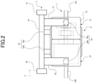
- FIG. 2 is a view illustrating the vehicle drive apparatus 1 viewed from the front of the vehicle.
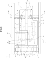
- FIG. 3 is a view illustrating the vehicle drive apparatus 1 viewed from above the vehicle.
- the vehicle using the vehicle drive apparatus 1 is an electric truck having a motor as a driving source for travel.
- a cab and a platform, which are not illustrated, are mounted on a ladder frame 2.
- the ladder frame 2 includes the paired left and right side rails 4L and 4R extending in a vehicle front-and-rear direction Y, and a plurality of cross members 6F and 6R arranged between the side rails 4L and 4R.
- the paired side rails 4L and 4R are arranged with a predetermined distance therebetween in a vehicle width direction X.
- the cross members 6F and 6R extend in the vehicle width direction X. Both ends of each cross member 6F or 6R are connected to the respective side rails 4L and 4R.
- the plurality of the cross members 6F and 6R are arranged with a predetermined distance therebetween in the vehicle front-and-rear direction Y
- a drive unit 8 of the vehicle is arranged below the ladder frame 2.
- the cross members 6 may have any shape as far as they can support the drive unit 8 via couplers 28a, 28b, 29a, and 29b described later.
- the drive unit 8 includes a motor 10 that is a driving source for travel of the vehicle, a transmission 20 housed in a gearbox 12 connected to the motor 10, and a differential device (differential) 14 connected to the transmission 20.
- the motor 10 is driven by electric power supplied from an unillustrated battery mounted on the vehicle, thereby generating a driving force.
- a pair of drive shafts 16L and 16R are coupled to the differential device 14.
- the transmission 20 includes a plurality of gears 20a and 20b.
- a rotary shaft 18 of the motor 10 is coupled to the gear 20a on the input side of the transmission 20.
- the transmission 20 changes high rotation/low torque input from the motor 10 to convert the high rotation/low torque into low rotation/high torque and output the low rotation/high torque.
- the differential device 14 includes a differential gear 24, to which the gear 20b on the output side of the transmission 20 is connected. Thus, the reduced output from the transmission 20 is input to the differential device 14.
- the driving force of the motor 10 is transmitted to the differential device 14 through the transmission 20.
- the differential device 14 transmits the driving force input from the gearbox 12 to the pared left and right of drive shafts 16L and 16R, and then to unillustrated wheels through paired left and right output shafts at a predetermined ratio in accordance with a travel state of the vehicle. This enables the vehicle to travel.
- the motor 10, the transmission 20, and the differential device 14 are housed in a drive unit housing 25 constituting the drive unit 8, and are integrally configured as the drive unit 8.
- the drive unit housing 25 is supported, at its motor-side end region, by the two couplers 28a and 28b constituting a motor-side support 28 to be coupled to the cross member 6F constituting the ladder frame 2.
- the cross member 6F is coupled to support members 7L and 7R extending downward in a vehicle height direction Z from the cross member 6F, and the support members 7L and 7R are coupled to the couplers 28a and 28b.
- the drive unit housing 25 is supported by, at its differential-side end region, by the two couplers 29a and 29b constituting a differential-side support 29 to be coupled to the cross member 6R that constitutes the ladder frame 2.
- the drive unit housing 25 is coupled to the couplers 28a and 28b, the couplers 29a and 29b, and the cross members 6F and 6R, thereby supporting the vehicle drive apparatus 1 below the ladder frame 2 in the vehicle height direction Z.
- the two couplers 28a and 28b of the motor-side support 28 are located at the same positions with respect to the vehicle front-and-rear direction Y That is, a virtual line (long dashed short dashed line of FIG.
- the couplers 28a' and 28b' indicated by a dotted line of FIG. 3 are couplers of a comparative example described later.
- the two couplers 28a and 28b of the motor-side support 28 are arranged farther outside in the vehicle width direction X than the couplers 29a and 29b of the differential-side support 29, respectively.
- the coupler 28a and 29a are compared, the coupler 28a is arranged closer to the side rail 4L than the coupler 29a is, i.e., the coupler 28a is arranged farther outside in the vehicle width direction X as viewed from the vehicle center, i.e., the center between the side rails 4L and 4R.
- the coupler 28b is arranged closer to the side rail 4R than the coupler 29a is, i.e., the coupler 28b is arranged farther outside in the vehicle width direction X as viewed from the vehicle center, i.e., the center between the side rails 4L and 4R.
- virtual lines (long dashed short dashed lines of FIG.
- couplers 28a and 28b of the motor-side support 28 are arranged at lower positions in the vehicle height direction Z than the couplers 28a and 28b of the differential-side support 29, as illustrated in FIG. 2 .
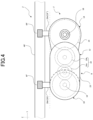
- FIG. 4 is a view schematically illustrating the vehicle drive apparatus 1' of the comparative example of the present invention from the side of a vehicle. For convenience of explanation of features, FIG.
- FIG. 4 employs a viewpoint illustrating, of a pair of side rails 4L' and 4R', only a side rail 4R' located on the back side in lateral view.
- FIG. 5 is a view illustrating the vehicle drive apparatus 1' from the front of the vehicle.
- FIG. 6 is a view illustrating the vehicle drive apparatus 1' from above the vehicle.
- the drive unit housing 25' is supported, at its motor-side end region, by the two couplers 28a' and 28b' constituting a motor-side support 28' to be coupled to the cross member 6F' constituting the ladder frame 2'.
- the drive unit housing 25' is supported by, at its differential-side end region, by the two couplers 29a' and 29b' constituting a differential-side support 29' to be coupled to the cross member 6R' that constitutes the ladder frame 2'.
- the drive unit housing 25' is coupled to the couplers 28a' and 28b', the couplers 29a' and 29b', and the cross members 6F' and 6R', thereby supporting the vehicle drive apparatus 1 on the ladder frame 2'.
- the two couplers 28a' and 28b' of the motor-side support 28' are arranged at the same positions with respect to the vehicle width direction X as the couplers 29a' and 29b' of the differential-side support 29', respectively.
- virtual lines (long dashed short dashed lines of FIG. 6 ) connecting the couplers 28a' and 28b' and the couplers 29a' and 29b', respectively, form a trapezoid with the line between the two couplers 28a' and 28b' of the motor-side support 29 being a lower base and with the line between the two couplers 29a' and 29b' of the differential-side support 29 being an upper base in plan view from above the vehicle shown in FIG. 6 .
- couplers 28a' and 28b' of the motor-side support 28 are arranged at lower positions in the vehicle height direction Z than the couplers 29a' and 29b' of the differential-side support 29, as illustrated in FIG. 5 .
- the moment produced in the drive unit 8 is input to the ladder frame 2 (the ladder frame 2' of the comparative example) through the couplers 28a and 28b (the couplers 28a' and 28b' of the comparative example) and the couplers 29a and 29b (the couplers 29a' and 29b' of the comparative example).
- the rolling and pitching of the drive unit 8 are desired to be in phase with the rolling and pitching of the vehicle from the viewpoint of travel stability.
- the couplers 28a and 28b (the couplers 28a' and 28b' of the comparative example) and the couplers 29a and 29b (the couplers 29a' and 29b' of the comparative example) have low attachment rigidity, it causes the rolling and pitching of the drive unit 8 and the rolling and pitching of the vehicle to be out of phase with each other, thereby lowering the travel stability.
- the term “rolling” means the side-to-side motion of the vehicle about an axis in the vehicle front-and-rear direction Y
- the term “pitching" means the front-rear motion of the vehicle about an axis in the vehicle width direction X.
- the two couplers 28a and 28b of the motor-side support 28 are arranged farther outside in the vehicle width direction X than the couplers 29a and 29b of the differential-side support 29, respectively.
- the two couplers 28a' and 28b' of the motor-side support 28' are arranged at the same positions with respect to the vehicle width direction X as the couplers 29a' and 29b' of the differential-side support 29', respectively.
- the rolling of the drive unit 8 accompanying the rolling of the vehicle will now be discussed.
- the drive unit 8 also rolls.
- the drive unit housing 25 housing the drive unit 8 of the embodiment has a larger distance in the vehicle width direction X between the couplers 28a and 28b that constitute the motor-side support 28 near the motor 10, which is a heavy object, than in the case of the comparative example. That is, the couplers 28a and 28b are arranged farther from the center of rolling that is the center of gravity of the drive unit 8. Thus, the couplers 28a and 28b receive a smaller moment during the rolling of the drive unit 8.
- the drive unit housing 25 housing the drive unit 8 in the embodiment moves about an axis (long dashed short dashed line of FIG. 1 ) connecting the motor-side support 28 and the differential-side support 29 in lateral view of FIG. 1 .
- an axis (long dashed short dashed line of FIG. 4 ) connecting the motor-side support 28' and the differential-side support 29' is located above the drive unit housing 25' in the vehicle height direction Z.
- the drive unit 8 which is a heavy object, tends to move strongly during the rolling of the vehicle.
- the motor-side support 28 is arranged at the lower position in the vehicle height direction Z than the differential-side support 29.
- the axis (long dashed short dashed line of FIG. 1 ) connecting the motor-side support 28 and the differential-side support 29 passes through the inside of the drive unit housing 25.
- the motor-side support 28 is also provided close to the center of gravity of the motor 10, which is a heavy object of the components of the drive unit 8. That is, the axis (long dashed short dashed line of FIG. 1 ) connecting the motor-side support 28 and the differential-side support 29 passes close by the center of gravity of the drive unit 8.
- the motor 10 is a heavy object of the components of the drive unit 8 as described above, thereby causing the motor-side end region and the differential-side end region of the drive unit housing 25 to move differently during the rolling of the drive unit 8. This may result in large rolling of the motor-side end region.
- the virtual line (long dashed short dashed line of FIG. 6 ) connecting the couplers 28a' and 28b' and the couplers 29a' and 29b' forms the rectangle with the line between the two couplers 28a and 28b of the motor-side support 28 being the lower side and with the line between the two couplers 29a and 29b of the differential-side support 29 being the upper side in plan view from above the vehicle of FIG. 6 .
- the virtual line (long dashed short dashed line of FIG. 3 ) connecting the couplers 28a and 28b and the couplers 29a and 29b forms the trapezoid that is line symmetric in the vehicle width direction X (a line-symmetric axis: extending in the vehicle front-and-rear direction Y) with the line between the two couplers 28a and 28b of the motor-side support 28 being the lower base and with the line between the two couplers 29a and 29b of the differential-side support 29 being the upper base in plan view from above the vehicle of FIG. 3 .
- the roll axial centers of the drive apparatus and the vehicle which are separate mass bodies independent of each other, need to correspond to each other as much as possible in order to improve the roll performance of the vehicle as a whole.
- the drive unit housing 25 housing the drive unit 8 of the embodiment has a larger distance in the vehicle front-and-rear direction Y between the couplers 28a and 28b constituting the motor-side support 28 near the motor 10, which is a heavy object, and the couplers 29a and 29b constituting the differential-side support 29 than in the case of the comparative example. That is, the couplers 28a and 28b are arranged farther from the center of pitching that is the center of gravity of the drive unit 8. Thus, the couplers 28a and 28b receive a smaller moment during the pitching of the drive unit 8.
- the rotating moment acting on the drive unit 8 can be supported at a farther position.
- This allows the drive unit 8 to be supported on the ladder frame 2 while reducing increase in size and weight of the couplers 28a and 28b of the motor-side support 28 of the embodiment, and makes it possible to improve the stability of the drive unit 8 during the driving of the motor 10.
- the vehicle drive apparatus 1 of the present embodiment includes the drive unit including the motor 10 for generating a driving force in the vehicle having the ladder frame 2, the transmission 20 for changing the driving force transmitted from the motor 10, and the differential device 14 for splitting the driving force transmitted from the transmission 20 and transmitting the forces split to the driving wheels of the vehicle.
- the vehicle drive apparatus 1 further includes the drive unit housing 25 that houses the drive unit 8 at least partly , the motor-side support 28 coupling the drive unit housing 25 to the ladder frame 2 by the two couplers arranged in the motor-side end region of the drive unit housing 25, and the differential-side support 29 coupling the drive unit housing 25 to the ladder frame 2 in the differential-side end region of the drive unit housing 25.
- the two couplers 28a and 28b of the motor-side support 28 are arranged farther outside in the vehicle width direction X than the differential-side support 29.
- the two couplers 28a and 28b are arranged farther from the center of rolling that is the center of gravity of the drive unit 8.
- couplers 28a and 28b receive a smaller moment during the rolling of the drive unit 8.
- This makes it possible to reduce the requirement of rigidity on the couplers 28a and 28b, thereby enabling the drive unit 8 to be supported on the ladder frame 2 while reducing increase in size and weight of the couplers, which are support devices. Consequently, the stability of the drive unit 8 during the rolling of the vehicle can be improved.
- the two couplers 28a and 28b of the motor-side support are arranged at the same positions with respect to the vehicle front-and-rear direction Y, and the virtual line connecting the two couplers 28a and 28b of the motor-side support 28 is parallel to the vehicle width direction X.
- the two couplers 28a and 28b receive equal forces. This makes it possible to reduce the requirement of rigidity on the two couplers 28a and 28b, thereby reducing increase in size and weight of the couplers 28a and 28b.
- the differential-side support 29 couples the drive unit housing 25 to the cross member 6R of the ladder frame 2 by the two couplers 29a and 29b arranged in the differential-side end region of the drive unit housing 25.
- employing the two couplers 29a and 29b as the differential-side support 29 can reduce stress concentration, thereby making it possible to reduce the requirement of rigidity on the couplers 29a and 29b, and to reduce increase in size and weight of the couplers 29a and 29b.
- the two couplers 28a and 28b of the motor-side support 28 and the two couplers 29a and 29b of the differential-side support 29 are arranged such that the virtual line connecting the two couplers 28a and 28b and the two couplers 29a and 29b forms the trapezoid that is line symmetric in the vehicle width direction with the line between the two couplers of the motor-side support 28 being the lower base in plan view from above the vehicle.
- the roll axial centers of the drive apparatus and the vehicle which are separate mass bodies independent of each other, need to correspond to each other as much as possible in order to improve the roll performance of the vehicle as a whole.
- the motor-side support 28 is arranged at the lower position in the vehicle height direction Z than the differential-side support 29.
- the axis connecting the motor-side support 28 and the differential-side support 29 passes through the inside of the drive unit housing 25.
- differential-side support 29 is composed of the two couplers 29a and 29b in the above embodiment, the differential-side support 29 may be composed of one coupler as a combination of the couplers 29a and 29b.
- FIG. 7 is a view schematically illustrating the vehicle drive apparatus 1" of the other embodiment of the present invention from the side of a vehicle.
- FIG. 7 employs a viewpoint illustrating, of a pair of side rails 4L" and 4R" described later, only a side rail 4R" located on the back side in lateral view.
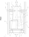
- FIG. 8 is a view illustrating the vehicle drive apparatus 1" from the front of the vehicle.
- FIG. 9 is a view illustrating the vehicle drive apparatus 1" from above the vehicle.
- the drive unit housing 25' is supported, at its motor-side end region, by the two couplers 28a' and 28b' constituting a motor-side support 28' to be coupled to the cross member 6F' constituting the ladder frame 2'.
- support members 7L" and 7R" extending upward from the cross member 6F" in the vehicle height direction Z are coupled to the cross member 6F
- the couplers 28a" and 28b" are coupled to the support members 7L" and 7R".
- the drive unit housing 25' is supported by, at its differential-side end region, by the two couplers 29a' and 29b' constituting a differential-side support 29' to be coupled to the cross member 6R' that constitutes the ladder frame 2'.
- the drive unit housing 25" is coupled to the couplers 28a" and 28b", the couplers 29a” and 29b", and the cross members 6F and 6R as described above, thereby supporting the vehicle drive apparatus 1" above the ladder frame 2" in the vehicle height direction Z.
- the two couplers 28a and 28b of the motor-side support 28 are arranged farther outside in the vehicle width direction X than the couplers 29a and 29b of the differential-side support 29, respectively.
- the coupler 28a" and 29a" are compared, the coupler 28a" is arranged closer to the side rail 4L” than the coupler 29a" is, i.e., the coupler 28a" is arranged farther outside in the vehicle width direction X as viewed from the vehicle center, i.e., the center between the side rails 4L" and 4R".
- the coupler 28b" is arranged closer to the side rail 4R" than the coupler 29a" is, i.e., the coupler 28b" is arranged farther outside in the vehicle width direction X as viewed from the vehicle center, i.e., the center between the side rails 4L" and 4R".
- a virtual line (long dashed short dashed line of FIG.
- the couplers 28a" and 28b" of the motor-side support 28" are also arranged at higher positions in the vehicle height direction Z than the couplers 28a" and 28b" of the differential-side support 29" as illustrated in FIG. 8 .
- the drive unit 8 is arranged above the ladder frame 2" in the vehicle height direction Z as described above.
- the motor-side support 28" of the vehicle drive apparatus 1" of the other embodiment of the present invention is arranged at the higher position in the vehicle height direction Z than the differential-side support 29".
- the drive unit housing 25" housing the drive unit 8 moves about an axis connecting the motor-side support 28" and the differential-side support 29" in lateral view of FIG. 7 in the embodiment.
- the motor-side support 28" is arranged at the higher position in the vehicle height direction Z than the differential-side support 29".
- the axis (long dashed short dashed line in FIG.
- the vehicle drive apparatus 1 is also applicable in a hybrid electric truck that uses an internal combustion engine as well as the motor 10.
- the vehicle drive apparatus 1 is not limited to the electric trucks but is also applicable in general commercial vehicles having the motor 10.
- the drive unit housing 25 houses the drive unit 8 in the above embodiments, the drive unit housing 25 may partly house the drive unit 8.
- the drive unit housing 25 houses the drive unit 8 in the above embodiments, the drive unit housing 25 may house part of the drive unit 8.
- the drive unit 8 may be a drive unit including a multi-stage transmission.
Landscapes
- Engineering & Computer Science (AREA)
- Chemical & Material Sciences (AREA)
- Combustion & Propulsion (AREA)
- Transportation (AREA)
- Mechanical Engineering (AREA)
- Arrangement Or Mounting Of Propulsion Units For Vehicles (AREA)
- Arrangement Of Transmissions (AREA)
- Motor Power Transmission Devices (AREA)
Description
- The present invention relates to a vehicle drive apparatus according to the preamble of
claim 1. - From the viewpoint of reducing environmental impact, electric trucks driven solely by electric motors without internal combustion have recently been developed in the field of commercial vehicles such as trucks. Such electric vehicles each include a drive unit that includes, for example, a motor and a power transmission mechanism such as a speed reducer composed of a plurality of gears, and can transmit a driving force of the motor to a differential gear to which driving wheels are coupled.
-
JP 2019 189 171 A claim 1 having a drive unit including a motor that generates a driving force in a vehicle with a ladder frame, a transmission that changes the driving force transmitted from the motor, and a differential that splits the driving force transmitted from the transmission and transmits the split forces to driving wheels of the vehicle, the vehicle drive apparatus further including: a drive unit housing at least partly housing the drive unit; a motor-side support coupling the drive unit housing to the ladder frame by two couplers arranged in a motor-side end region of the drive unit housing; and a differential-side support coupling the drive unit housing to the ladder frame in a differential-side end region of the drive unit housing. - When such a drive unit is mounted on an electric vehicle such as a commercial vehicle, the drive unit is supported by a ladder frame and a cross member.
- Unfortunately, for the electric trucks, driving torque generated by the motor is larger than that of passenger cars, thereby causing large torque reaction to occur in the drive unit during driving of the motor. Thus, a vehicle drive apparatus such as a bracket needs to have higher reliability, which may lead to increase in size and weight of a support device.
- Additionally, in the case of the electric trucks, the drive unit itself has a size and a weight that are larger than those of the passenger cars. Thus, a larger moment is produced in the drive unit during vehicle is rolling or pitching. In such a vehicle drive apparatus, the stability of the drive unit during vehicle rolling or pitching needs to be improved.
- The present invention has been achieved to solve at least some of such problems, and it is an object thereof to provide a vehicle drive apparatus capable of improving the stability of a drive unit during vehicle rolling or the like while reducing the risk of increase in size and weight of a support device.
- A vehicle drive apparatus according to
claim 1 includes a drive unit including a motor that generates a driving force in a vehicle with a ladder frame, a transmission that changes the driving force transmitted from the motor, and a differential that splits the driving force transmitted from the transmission and transmits the split forces to driving wheels of the vehicle, the vehicle drive apparatus further including: a drive unit housing at least partly housing the drive unit; a motor-side support coupling the drive unit housing to the ladder frame by two couplers arranged in a motor-side end region of the drive unit housing; and a differential-side support coupling the drive unit housing to the ladder frame in a differential-side end region of the drive unit housing. - The vehicle drive apparatus according to
claim 1 has a configuration in which the two couplers of the motor-side support are arranged on the outer side in the vehicle width direction than respective couplers serving as the differential-side support. As compared to a vehicle drive apparatus without such a configuration, the two couplers are arranged farther from the center of rolling that is the center of gravity of the drive unit as compared to a vehicle drive apparatus without such a configuration. Thus, it is possible to make the couplers receive a smaller moment during rolling of the drive unit. This makes it possible to reduce the requirement of rigidity on the couplers, thereby enabling the drive unit to be supported on the ladder frame while reducing increase in size and weight of the couplers, which are support devices. Consequently, the stability of the drive unit during rolling of the vehicle can be improved. - In the vehicle drive apparatus according to
claim 1, furthermore, the differential-side support may couple the drive unit housing to the ladder frame by two couplers arranged in the differential-side end region of the drive unit housing. As compared to when only one coupler is employed, employing the two couplers serving as the differential-side support can reduce stress concentration, thereby making it possible to reduce the requirement of rigidity on the couplers, and to reduce increase in size and weight of the couplers to be reduced. - In the vehicle drive apparatus according to
claim 2, a virtual line connecting the two couplers of the motor-side support is parallel to the vehicle width direction. That is, the two couplers of the motor-side support are arranged at the same positions with respect to a vehicle front-and-rear direction, and thus receive equal forces. This makes it possible to reduce the requirement of rigidity on the two couplers, thereby reducing increase in size and weight of the couplers to be reduced. - In the vehicle drive apparatus according to claim 3, the two couplers of the motor-side support and the two couplers of the differential-side support are arranged such that a virtual line connecting the two couplers of the motor-side support and the two couplers of the differential-side support forms a trapezoid that is line symmetric in the vehicle width direction with the line between the two couplers of the motor-side support being a lower base in plan view from above the vehicle.
- Arranging the four couplers, i.e., the couplers of the motor-side support and the couplers of the differential-side support such that the virtual line connecting the four couplers forms the trapezoid in plan view from above the vehicle as described above can improve the roll performance of the entire vehicle. To be more specific, the roll axial centers of the drive apparatus and the vehicle, which are mass bodies independent of each other, need to correspond to each other as much as possible in order to improve the roll performance of the entire vehicle. Arranging the two couplers of the motor-side support and the two couplers of the differential-side support so as to form the trapezoid that is line symmetric in the vehicle width direction allows the roll axial centers of the drive apparatus and the vehicle to easily correspond to each other, and the roll performance of the entire vehicle to be improved.
- In the vehicle drive apparatus according to claim 4, the motor-side support is arranged at a lower position in a vehicle height direction than the differential-side support. In such a configuration, an axis connecting the motor-side support and the differential-side support passes through the inside of the drive unit housing. This allows the couplers of the motor-side support to have lower rigidity, and thereby enables the drive unit to be supported on the ladder frame while reducing the increase in size and weight of the couplers serving as the support device. Consequently, the stability of the drive unit during rolling of the vehicle can be improved.
- In the vehicle drive apparatus according to claim 5, the motor-side support is arranged at a higher position in a vehicle height direction than the differential-side support. In such a configuration, an axis connecting the motor-side support and the differential-side support passes through the inside of the drive unit housing. This allows the couplers of the motor-side support to have lower rigidity, and thereby enables the drive unit to be supported on the ladder frame while reducing the increase in size and weight of the couplers serving as the support device. Consequently, the stability of the drive unit during rolling of the vehicle can be improved.
-
-
FIG. 1 is a view schematically illustrating a vehicle drive apparatus of an embodiment of the present invention viewed from the side of a vehicle. -
FIG. 2 is a view illustrating the vehicle drive apparatus ofFIG. 1 viewed from the front of the vehicle. -
FIG. 3 is a view illustrating the vehicle drive apparatus ofFIG. 1 viewed from above the vehicle. -
FIG. 4 is a view schematically illustrating a vehicle drive apparatus of a comparative example of the present invention viewed from the side of a vehicle. -
FIG. 5 is a view illustrating the vehicle drive apparatus ofFIG. 4 viewed from the front of the vehicle. -
FIG. 6 is a view illustrating the vehicle drive apparatus ofFIG. 4 viewed from above the vehicle. -
FIG. 7 is a view schematically illustrating a vehicle drive apparatus of another embodiment of the present invention viewed from the side of a vehicle. -
FIG. 8 is a view illustrating the vehicle drive apparatus ofFIG. 7 viewed from the front of the vehicle. -
FIG. 9 is a view illustrating the vehicle drive apparatus ofFIG. 7 viewed from above the vehicle. - Configurations of embodiments of the present invention will be described in detail below with reference to the drawings.
- The outline of a
vehicle drive apparatus 1 of an embodiment of the present invention will be described below with reference toFIGS. 1 to 3 .FIG. 1 is a view schematically illustrating thevehicle drive apparatus 1 according to the embodiment of the present invention viewed from the side of a vehicle. For convenience of explanation of features,FIG. 1 employs a viewpoint illustrating, of a pair ofside rails side rail 4R located on the back side in lateral view.FIG. 2 is a view illustrating thevehicle drive apparatus 1 viewed from the front of the vehicle.FIG. 3 is a view illustrating thevehicle drive apparatus 1 viewed from above the vehicle. - The vehicle using the
vehicle drive apparatus 1 is an electric truck having a motor as a driving source for travel. A cab and a platform, which are not illustrated, are mounted on aladder frame 2. Theladder frame 2 includes the paired left andright side rails cross members side rails - The paired
side rails cross members cross member respective side rails cross members Y A drive unit 8 of the vehicle is arranged below theladder frame 2. - The cross members 6 may have any shape as far as they can support the
drive unit 8 viacouplers - The
drive unit 8 includes amotor 10 that is a driving source for travel of the vehicle, atransmission 20 housed in agearbox 12 connected to themotor 10, and a differential device (differential) 14 connected to thetransmission 20. Themotor 10 is driven by electric power supplied from an unillustrated battery mounted on the vehicle, thereby generating a driving force. - A pair of
drive shafts differential device 14. Thetransmission 20 includes a plurality ofgears rotary shaft 18 of themotor 10 is coupled to thegear 20a on the input side of thetransmission 20. - The
transmission 20 changes high rotation/low torque input from themotor 10 to convert the high rotation/low torque into low rotation/high torque and output the low rotation/high torque. Thedifferential device 14 includes adifferential gear 24, to which thegear 20b on the output side of thetransmission 20 is connected. Thus, the reduced output from thetransmission 20 is input to thedifferential device 14. - As described above, the driving force of the
motor 10 is transmitted to thedifferential device 14 through thetransmission 20. Thedifferential device 14 transmits the driving force input from thegearbox 12 to the pared left and right ofdrive shafts - The
motor 10, thetransmission 20, and thedifferential device 14 are housed in adrive unit housing 25 constituting thedrive unit 8, and are integrally configured as thedrive unit 8. Thedrive unit housing 25 is supported, at its motor-side end region, by the twocouplers side support 28 to be coupled to thecross member 6F constituting theladder frame 2. To be more specific, thecross member 6F is coupled to supportmembers cross member 6F, and thesupport members couplers drive unit housing 25 is supported by, at its differential-side end region, by the twocouplers side support 29 to be coupled to thecross member 6R that constitutes theladder frame 2. As thus described above, thedrive unit housing 25 is coupled to thecouplers couplers cross members vehicle drive apparatus 1 below theladder frame 2 in the vehicle height direction Z. The twocouplers side support 28 are located at the same positions with respect to the vehicle front-and-rear direction Y That is, a virtual line (long dashed short dashed line ofFIG. 3 ) connecting the twocouplers couplers side support 29 are located at the same positions with respect to the vehicle front-and-rear direction Y That is, a virtual line (long dashed short dashed line ofFIG. 3 ) connecting the twocouplers couplers 28a' and 28b' indicated by a dotted line ofFIG. 3 are couplers of a comparative example described later. - The two
couplers side support 28 are arranged farther outside in the vehicle width direction X than thecouplers side support 29, respectively. With reference toFIG. 3 , when thecouplers coupler 28a is arranged closer to theside rail 4L than thecoupler 29a is, i.e., thecoupler 28a is arranged farther outside in the vehicle width direction X as viewed from the vehicle center, i.e., the center between the side rails 4L and 4R. When thecouplers coupler 28b is arranged closer to theside rail 4R than thecoupler 29a is, i.e., thecoupler 28b is arranged farther outside in the vehicle width direction X as viewed from the vehicle center, i.e., the center between the side rails 4L and 4R. Thus, virtual lines (long dashed short dashed lines ofFIG. 3 ) connecting thecouplers couplers couplers side support 28 being a lower base and with the line between the twocouplers side support 29 being an upper base in plan view from above the vehicle. - Further, the
couplers side support 28 are arranged at lower positions in the vehicle height direction Z than thecouplers side support 29, as illustrated inFIG. 2 . - Subsequently, the outline of a vehicle drive apparatus 1' of a comparative example of the present invention, which is also shown analogously in the above mentioned
JP 2019 189 171 A FIGS. 4 to 6 . The same components as those of the embodiment described above are indicated by the same reference signs to omit detailed description. Components having functions or the like corresponding to those of the above embodiment are indicated with ' added to the reference signs of the above embodiment.FIG. 4 is a view schematically illustrating the vehicle drive apparatus 1' of the comparative example of the present invention from the side of a vehicle. For convenience of explanation of features,FIG. 4 employs a viewpoint illustrating, of a pair of side rails 4L' and 4R', only aside rail 4R' located on the back side in lateral view.FIG. 5 is a view illustrating the vehicle drive apparatus 1' from the front of the vehicle.FIG. 6 is a view illustrating the vehicle drive apparatus 1' from above the vehicle. - The drive unit housing 25' is supported, at its motor-side end region, by the two
couplers 28a' and 28b' constituting a motor-side support 28' to be coupled to thecross member 6F' constituting the ladder frame 2'. The drive unit housing 25' is supported by, at its differential-side end region, by the twocouplers 29a' and 29b' constituting a differential-side support 29' to be coupled to thecross member 6R' that constitutes the ladder frame 2'. As thus described above, the drive unit housing 25' is coupled to thecouplers 28a' and 28b', thecouplers 29a' and 29b', and thecross members 6F' and 6R', thereby supporting thevehicle drive apparatus 1 on the ladder frame 2'. - The two
couplers 28a' and 28b' of the motor-side support 28' are arranged at the same positions with respect to the vehicle width direction X as thecouplers 29a' and 29b' of the differential-side support 29', respectively. Thus, virtual lines (long dashed short dashed lines ofFIG. 6 ) connecting thecouplers 28a' and 28b' and thecouplers 29a' and 29b', respectively, form a trapezoid with the line between the twocouplers 28a' and 28b' of the motor-side support 29 being a lower base and with the line between the twocouplers 29a' and 29b' of the differential-side support 29 being an upper base in plan view from above the vehicle shown inFIG. 6 . - Further, the
couplers 28a' and 28b' of the motor-side support 28 are arranged at lower positions in the vehicle height direction Z than thecouplers 29a' and 29b' of the differential-side support 29, as illustrated inFIG. 5 . - Next, the comparison between the embodiment and the comparative example described above will be described.
- When the vehicle rolls or pitches during travel, a larger moment is produced in the
drive unit 8 that is a heavy object. Thus, the moment produced in thedrive unit 8 is input to the ladder frame 2 (the ladder frame 2' of the comparative example) through thecouplers couplers 28a' and 28b' of the comparative example) and thecouplers couplers 29a' and 29b' of the comparative example). The rolling and pitching of thedrive unit 8 are desired to be in phase with the rolling and pitching of the vehicle from the viewpoint of travel stability. However, if thecouplers couplers 28a' and 28b' of the comparative example) and thecouplers couplers 29a' and 29b' of the comparative example) have low attachment rigidity, it causes the rolling and pitching of thedrive unit 8 and the rolling and pitching of the vehicle to be out of phase with each other, thereby lowering the travel stability. The term "rolling" means the side-to-side motion of the vehicle about an axis in the vehicle front-and-rear direction Y, and the term "pitching" means the front-rear motion of the vehicle about an axis in the vehicle width direction X. - In the configuration of the embodiment, the two
couplers side support 28 are arranged farther outside in the vehicle width direction X than thecouplers side support 29, respectively. In contrast, in the configuration of the comparative example, the twocouplers 28a' and 28b' of the motor-side support 28' are arranged at the same positions with respect to the vehicle width direction X as thecouplers 29a' and 29b' of the differential-side support 29', respectively. - The rolling of the
drive unit 8 accompanying the rolling of the vehicle will now be discussed. When the vehicle rolls, thedrive unit 8 also rolls. Thedrive unit housing 25 housing thedrive unit 8 of the embodiment has a larger distance in the vehicle width direction X between thecouplers side support 28 near themotor 10, which is a heavy object, than in the case of the comparative example. That is, thecouplers drive unit 8. Thus, thecouplers drive unit 8. This makes it possible to reduce the requirement of rigidity on thecouplers drive unit 8 to be supported on theladder frame 2 while reducing increase in size and weight of thecouplers drive unit 8 during the rolling of the vehicle can be improved. - When the vehicle rolls, the
drive unit housing 25 housing thedrive unit 8 in the embodiment moves about an axis (long dashed short dashed line ofFIG. 1 ) connecting the motor-side support 28 and the differential-side support 29 in lateral view ofFIG. 1 . In the comparative example, an axis (long dashed short dashed line ofFIG. 4 ) connecting the motor-side support 28' and the differential-side support 29' is located above the drive unit housing 25' in the vehicle height direction Z. Thus, thedrive unit 8, which is a heavy object, tends to move strongly during the rolling of the vehicle. In contrast, in the embodiment, the motor-side support 28 is arranged at the lower position in the vehicle height direction Z than the differential-side support 29. Thus, the axis (long dashed short dashed line ofFIG. 1 ) connecting the motor-side support 28 and the differential-side support 29 passes through the inside of thedrive unit housing 25. The motor-side support 28 is also provided close to the center of gravity of themotor 10, which is a heavy object of the components of thedrive unit 8. That is, the axis (long dashed short dashed line ofFIG. 1 ) connecting the motor-side support 28 and the differential-side support 29 passes close by the center of gravity of thedrive unit 8. This makes it possible to reduce the requirement of rigidity on thecouplers drive unit 8 to be supported on theladder frame 2 while reducing increase in size and weight of thecouplers drive unit 8 during the rolling of the vehicle can be improved. - Additionally, the
motor 10 is a heavy object of the components of thedrive unit 8 as described above, thereby causing the motor-side end region and the differential-side end region of thedrive unit housing 25 to move differently during the rolling of thedrive unit 8. This may result in large rolling of the motor-side end region. In the comparative example, the virtual line (long dashed short dashed line ofFIG. 6 ) connecting thecouplers 28a' and 28b' and thecouplers 29a' and 29b' forms the rectangle with the line between the twocouplers side support 28 being the lower side and with the line between the twocouplers side support 29 being the upper side in plan view from above the vehicle ofFIG. 6 . In contrast, in the embodiment, the virtual line (long dashed short dashed line ofFIG. 3 ) connecting thecouplers couplers couplers side support 28 being the lower base and with the line between the twocouplers side support 29 being the upper base in plan view from above the vehicle ofFIG. 3 . - As described above, arranging the four couplers, i.e., the
couplers side support 28 and thecouplers side support 29 such that the virtual line connecting the four couplers forms the trapezoid in plan view from above the vehicle can improve the roll performance of the vehicle as a whole. To be more specific, the roll axial centers of the drive apparatus and the vehicle, which are separate mass bodies independent of each other, need to correspond to each other as much as possible in order to improve the roll performance of the vehicle as a whole. Hence, as shown inFIG. 3 , arranging the four couplers such that the twocouplers - Subsequently, the pitching of the
drive unit 8 accompanying the pitching of the vehicle will be discussed. When the vehicle pitches, thedrive unit 8 also pitches. Thedrive unit housing 25 housing thedrive unit 8 of the embodiment has a larger distance in the vehicle front-and-rear direction Y between thecouplers side support 28 near themotor 10, which is a heavy object, and thecouplers side support 29 than in the case of the comparative example. That is, thecouplers drive unit 8. Thus, thecouplers drive unit 8. This makes it possible to reduce the requirement of rigidity on thecouplers drive unit 8 to be supported on theladder frame 2 while reducing increase in size and weight of thecouplers drive unit 8 during the pitching of the vehicle can be improved. - Subsequently, torque reaction in excitation of the
motor 10 will be discussed. When themotor 10 is excited, therotary shaft 18 rotates to transmit the rotation to thedifferential gear 24 of thedifferential device 14 through thetransmission 20, thereby rotating the wheels via the pair ofdrive shafts drive unit 8, a rotating moment about thedrive shafts drive shafts couplers side support 28 of the embodiment is larger than the distance to thecouplers 28a' and 28b' of the motor-side support 28' of the comparative example. That is, the rotating moment acting on thedrive unit 8 can be supported at a farther position. This allows thedrive unit 8 to be supported on theladder frame 2 while reducing increase in size and weight of thecouplers side support 28 of the embodiment, and makes it possible to improve the stability of thedrive unit 8 during the driving of themotor 10. - As described above, the
vehicle drive apparatus 1 of the present embodiment includes the drive unit including themotor 10 for generating a driving force in the vehicle having theladder frame 2, thetransmission 20 for changing the driving force transmitted from themotor 10, and thedifferential device 14 for splitting the driving force transmitted from thetransmission 20 and transmitting the forces split to the driving wheels of the vehicle. Thevehicle drive apparatus 1 further includes thedrive unit housing 25 that houses thedrive unit 8 at least partly , the motor-side support 28 coupling thedrive unit housing 25 to theladder frame 2 by the two couplers arranged in the motor-side end region of thedrive unit housing 25, and the differential-side support 29 coupling thedrive unit housing 25 to theladder frame 2 in the differential-side end region of thedrive unit housing 25. The twocouplers side support 28 are arranged farther outside in the vehicle width direction X than the differential-side support 29. - As compared to a vehicle drive apparatus without such a configuration, the two
couplers drive unit 8. Thus, it is possible to makecouplers drive unit 8. This makes it possible to reduce the requirement of rigidity on thecouplers drive unit 8 to be supported on theladder frame 2 while reducing increase in size and weight of the couplers, which are support devices. Consequently, the stability of thedrive unit 8 during the rolling of the vehicle can be improved. - The two
couplers couplers side support 28 is parallel to the vehicle width direction X. Thus, the twocouplers couplers couplers - The differential-
side support 29 couples thedrive unit housing 25 to thecross member 6R of theladder frame 2 by the twocouplers drive unit housing 25. As compared to when only one coupler is employed, employing the twocouplers side support 29 can reduce stress concentration, thereby making it possible to reduce the requirement of rigidity on thecouplers couplers - The two
couplers side support 28 and the twocouplers side support 29 are arranged such that the virtual line connecting the twocouplers couplers side support 28 being the lower base in plan view from above the vehicle. As described above, arranging the four couplers, i.e., thecouplers side support 28 and thecouplers side support 29 such that the virtual line connecting the four couplers forms the trapezoid in plan view from above the vehicle can improve the roll performance of the vehicle as a whole. To be more specific, the roll axial centers of the drive apparatus and the vehicle, which are separate mass bodies independent of each other, need to correspond to each other as much as possible in order to improve the roll performance of the vehicle as a whole. Hence, as shown inFIG. 3 , arranging the four couplers such that the twocouplers - The motor-
side support 28 is arranged at the lower position in the vehicle height direction Z than the differential-side support 29. Thus, the axis connecting the motor-side support 28 and the differential-side support 29 passes through the inside of thedrive unit housing 25. This makes it possible to reduce the requirement of rigidity on thecouplers side support 28, thereby enabling the drive unit to be supported on thesupport members cross member 6F of theladder frame 2 while reducing increase in size and weight of thecouplers drive unit 8 during the rolling of the vehicle can be improved. - Although the differential-
side support 29 is composed of the twocouplers side support 29 may be composed of one coupler as a combination of thecouplers - Next, an outline of a
vehicle drive apparatus 1" according to another embodiment of the present invention will be described with reference toFIGS. 7 to 9 . The same components as those of the embodiment described above are indicated by the same reference signs to omit detailed description. Components having functions or the like corresponding to those of the above embodiment are indicated with " added to the reference signs of the above embodiment.FIG. 7 is a view schematically illustrating thevehicle drive apparatus 1" of the other embodiment of the present invention from the side of a vehicle. For convenience of explanation of features,FIG. 7 employs a viewpoint illustrating, of a pair ofside rails 4L" and 4R" described later, only aside rail 4R" located on the back side in lateral view.FIG. 8 is a view illustrating thevehicle drive apparatus 1" from the front of the vehicle.FIG. 9 is a view illustrating thevehicle drive apparatus 1" from above the vehicle. - The drive unit housing 25' is supported, at its motor-side end region, by the two
couplers 28a' and 28b' constituting a motor-side support 28' to be coupled to thecross member 6F' constituting the ladder frame 2'. To be more specific,support members 7L" and 7R" extending upward from thecross member 6F" in the vehicle height direction Z are coupled to thecross member 6F", and thecouplers 28a" and 28b" are coupled to thesupport members 7L" and 7R". The drive unit housing 25' is supported by, at its differential-side end region, by the twocouplers 29a' and 29b' constituting a differential-side support 29' to be coupled to thecross member 6R' that constitutes the ladder frame 2'. Thedrive unit housing 25" is coupled to thecouplers 28a" and 28b", thecouplers 29a" and 29b", and thecross members vehicle drive apparatus 1" above theladder frame 2" in the vehicle height direction Z. - The two
couplers side support 28 are arranged farther outside in the vehicle width direction X than thecouplers side support 29, respectively. With reference toFIG. 9 , when thecouplers 28a" and 29a" are compared, thecoupler 28a" is arranged closer to theside rail 4L" than thecoupler 29a" is, i.e., thecoupler 28a" is arranged farther outside in the vehicle width direction X as viewed from the vehicle center, i.e., the center between the side rails 4L" and 4R". Similarly, when thecouplers 28b" and 29b" are compared, thecoupler 28b" is arranged closer to theside rail 4R" than thecoupler 29a" is, i.e., thecoupler 28b" is arranged farther outside in the vehicle width direction X as viewed from the vehicle center, i.e., the center between the side rails 4L" and 4R". Thus, a virtual line (long dashed short dashed line ofFIG. 9 ) connecting thecouplers 28a" and 28b" and thecouplers 29a" and 29b" forms a trapezoid with the line between the twocouplers 28a" and 28b" of the motor-side support 28" being a lower base, and the line between the twocouplers 29a" and 29b" of the differential-side support 29" being an upper base in plan view from above the vehicle. - The
couplers 28a" and 28b" of the motor-side support 28" are also arranged at higher positions in the vehicle height direction Z than thecouplers 28a" and 28b" of the differential-side support 29" as illustrated inFIG. 8 . - In the
vehicle drive apparatus 1" of the other embodiment of the present invention, thedrive unit 8 is arranged above theladder frame 2" in the vehicle height direction Z as described above. As illustrated inFIGS. 7 and8 , the motor-side support 28" of thevehicle drive apparatus 1" of the other embodiment of the present invention is arranged at the higher position in the vehicle height direction Z than the differential-side support 29". When the vehicle rolls, thedrive unit housing 25" housing thedrive unit 8 moves about an axis connecting the motor-side support 28" and the differential-side support 29" in lateral view ofFIG. 7 in the embodiment. The motor-side support 28" is arranged at the higher position in the vehicle height direction Z than the differential-side support 29". Thus, the axis (long dashed short dashed line inFIG. 7 ) connecting the motor-side support 28" and the differential-side support 29" passes through the inside of thedrive unit housing 25". The motor-side support 28 is also arranged close to the center of gravity of themotor 10, which is a heavy object of the components of thedrive unit 8. That is, the axis (long dashed short dashed line inFIG. 7 ) connecting the motor-side support 28" and the differential-side support 29" passes close by the center of gravity of thedrive unit 8. This makes it possible to reduce the requirement of rigidity on thecouplers 28a" and 28b", thereby enabling thedrive unit 8 to be supported on theladder frame 2" while reducing increase in size and weight of thecouplers 28a" and 28b", which are support devices. Consequently, the stability of thedrive unit 8 during the rolling of the vehicle can be improved even when thedrive unit 8 is arranged above theladder frame 2" in the vehicle height direction Z. - Although the above embodiments have been described by using the electric truck having only the
motor 10 as the driving source for travel as an example, thevehicle drive apparatus 1 is also applicable in a hybrid electric truck that uses an internal combustion engine as well as themotor 10. Thevehicle drive apparatus 1 is not limited to the electric trucks but is also applicable in general commercial vehicles having themotor 10. - Although the
drive unit housing 25 houses thedrive unit 8 in the above embodiments, thedrive unit housing 25 may partly house thedrive unit 8. - Although the
drive unit housing 25 houses thedrive unit 8 in the above embodiments, thedrive unit housing 25 may house part of thedrive unit 8. - Although the above embodiments have been described by using the
drive unit 8 having thetransmission 20 as an example, thedrive unit 8 according to the present invention may be a drive unit including a multi-stage transmission. -
- 1
- Vehicle Drive Apparatus
- 2
- Ladder Frame
- 4L, 4R
- Side Rail
- 6F, 6R
- Cross Member
- 7L, 7R
- Support Member
- 8
- Drive Unit
- 10
- Motor
- 14
- Differential Device
- 16L, 16R
- Drive Shaft
- 18
- Rotary Shaft
- 20
- Transmission
- 20a, 20b
- Transmission Gear
- 24
- Differential Gear
- 25
- Drive Unit Housing
- 28
- Motor-side Support
- 28a, 28b
- Coupler
- 29
- Differential-side Support
- 29a, 29b
- Coupler
Claims (5)
- A vehicle drive apparatus (1) having a drive unit (8) including: a motor (10) that generates a driving force in a vehicle with a ladder frame (2); a transmission (20) that changes the driving force transmitted from the motor (10); and a differential that splits the driving force transmitted from the transmission (20) and transmits forces split to driving wheels of the vehicle, the vehicle drive apparatus (1) further comprising:a drive unit housing (25) that houses at least part of the drive unit (8);a motor-side support (28) coupling the drive unit housing (25) to the ladder frame (2) by two couplers (28a, 28b) arranged in a motor-side end region of the drive unit housing (25); anda differential-side support (29) coupling the drive unit housing (25) to the ladder frame (2) in a differential-side end region of the drive unit housing (25),
characterized in thatthe two couplers (29a, 29b) of the motor-side support (28) being arranged farther outside in a vehicle width direction than the differential-side support (29),and that the differential-side support (29) couples the drive unit housing (25) to the ladder frame (2) by two couplers (29a, 29b) arranged in the differential-side end region of the drive unit housing (25). - The vehicle drive apparatus (1) of claim 1, wherein
a virtual line connecting the two couplers of the motor-side support is parallel to the vehicle width direction. - The vehicle drive apparatus (1) of claim 1 or 2, wherein
the two couplers (28a, 28b) of the motor-side support (28) and the two couplers (29a, 29b) of the differential-side support (29) are arranged such that a virtual line connecting the two couplers (28q, 28b) of the motor-side support (28) and the two couplers (29a, 29b) of the differential-side support (29) forms a trapezoid that is line symmetric in the vehicle width direction with a line between the two couplers (28a, 28b) of the motor-side support (28) being a lower base in plan view from above the vehicle. - The vehicle drive apparatus (1) of any one of claims 1 to 3, wherein
the motor-side support (28) is arranged at a lower position in a vehicle height direction than the differential-side support (29). - The vehicle drive apparatus (1) of any one of claims 1 to 4, wherein
the motor-side support (28) is arranged at a higher position in a vehicle height direction than the differential-side support (29).
Applications Claiming Priority (2)
| Application Number | Priority Date | Filing Date | Title |
|---|---|---|---|
| JP2019229733A JP7395814B2 (en) | 2019-12-19 | 2019-12-19 | Vehicle drive system |
| PCT/JP2020/039668 WO2021124675A1 (en) | 2019-12-19 | 2020-10-22 | Vehicle drive apparatus |
Publications (3)
| Publication Number | Publication Date |
|---|---|
| EP4079552A1 EP4079552A1 (en) | 2022-10-26 |
| EP4079552A4 EP4079552A4 (en) | 2023-06-14 |
| EP4079552B1 true EP4079552B1 (en) | 2024-08-21 |
Family
ID=76477158
Family Applications (1)
| Application Number | Title | Priority Date | Filing Date |
|---|---|---|---|
| EP20902567.5A Active EP4079552B1 (en) | 2019-12-19 | 2020-10-22 | Vehicle drive apparatus |
Country Status (5)
| Country | Link |
|---|---|
| US (1) | US12275295B2 (en) |
| EP (1) | EP4079552B1 (en) |
| JP (1) | JP7395814B2 (en) |
| CN (1) | CN114845895B (en) |
| WO (1) | WO2021124675A1 (en) |
Families Citing this family (2)
| Publication number | Priority date | Publication date | Assignee | Title |
|---|---|---|---|---|
| JP7395814B2 (en) * | 2019-12-19 | 2023-12-12 | メルセデス・ベンツ グループ アクチェンゲゼルシャフト | Vehicle drive system |
| US12397867B2 (en) * | 2023-12-22 | 2025-08-26 | Kubota Corporation | Work machine |
Family Cites Families (33)
| Publication number | Priority date | Publication date | Assignee | Title |
|---|---|---|---|---|
| JP3613088B2 (en) | 1999-09-10 | 2005-01-26 | 日産自動車株式会社 | Vehicle drive unit support device |
| CN1127416C (en) * | 2000-11-03 | 2003-11-12 | 深圳明华环保汽车有限公司 | Composite electric enviromental protection automobile |
| CN2471599Y (en) * | 2001-03-29 | 2002-01-16 | 山东黑豹股份有限公司 | Electric vehicle braking energy recovery device with generator |
| CN2556060Y (en) * | 2002-07-23 | 2003-06-18 | 张辉隆 | Improved gear box variable speed transmission structure for electric vehicles |
| JP2011111141A (en) * | 2009-11-30 | 2011-06-09 | Hitachi Ltd | Chassis frame for electric vehicle, and electric vehicle |
| US9030063B2 (en) | 2010-12-17 | 2015-05-12 | Tesla Motors, Inc. | Thermal management system for use with an integrated motor assembly |
| JP6014599B2 (en) | 2011-11-09 | 2016-10-25 | 日立オートモティブシステムズ株式会社 | Electric vehicle drive system |
| EP2977251A1 (en) | 2013-03-18 | 2016-01-27 | Hitachi Automotive Systems, Ltd. | Drive device for electric vehicle |
| EP3025889A4 (en) * | 2013-07-24 | 2017-03-08 | Aleees Eco Ark (Cayman) Co. LTD. | Detachable high-voltage isolation structure of large-sized electric vehicle |
| JP2016132326A (en) * | 2015-01-16 | 2016-07-25 | トヨタ自動車株式会社 | Electric vehicle, holding mechanism, and electric vehicle manufacturing method |
| CA2972285C (en) * | 2015-03-26 | 2018-08-14 | Services Automobiles Grantuned Inc. | A fuel to electric reusable conversion kit and a method of converting and reusing the conversion kit |
| US10654465B2 (en) * | 2015-07-02 | 2020-05-19 | Volvo Truck Corporation | Method for controlling a hydraulic hybrid vehicle |
| DE102016006208A1 (en) * | 2016-05-19 | 2017-11-23 | Man Truck & Bus Ag | Battery-electric commercial vehicle, in particular lorries |
| JP2018016126A (en) | 2016-07-26 | 2018-02-01 | ダイムラー・アクチェンゲゼルシャフトDaimler AG | Power transmission device for electric truck |
| US10144411B2 (en) * | 2017-01-13 | 2018-12-04 | Gregorio M. Belloso | Vehicle system |
| JP6447642B2 (en) * | 2017-01-16 | 2019-01-09 | マツダ株式会社 | Electric vehicle |
| WO2019044262A1 (en) | 2017-08-31 | 2019-03-07 | ダイムラー・アクチェンゲゼルシャフト | Vehicular drive unit |
| EP3751707B1 (en) * | 2018-02-12 | 2023-04-12 | BYD Company Limited | Electric assembly and vehicle having same |
| US10967724B2 (en) * | 2018-02-24 | 2021-04-06 | Richard Chi-Hsueh | Vehicle |
| JP2019166944A (en) * | 2018-03-23 | 2019-10-03 | ダイムラー・アクチェンゲゼルシャフトDaimler AG | Vehicle cross member |
| JP2019189171A (en) | 2018-04-27 | 2019-10-31 | ダイムラー・アクチェンゲゼルシャフトDaimler AG | Drive unit support device |
| JP7057712B2 (en) * | 2018-04-27 | 2022-04-20 | ダイムラー・アクチェンゲゼルシャフト | Vehicle battery pack support |
| CN109278517A (en) * | 2018-10-13 | 2019-01-29 | 合肥美桥汽车传动及底盘系统有限公司 | A non-load-bearing independent drive electric axle |
| US11365797B2 (en) * | 2018-10-22 | 2022-06-21 | Nidec Corporation | Motor assembly |
| JP7155925B2 (en) * | 2018-11-16 | 2022-10-19 | トヨタ自動車株式会社 | Vehicle drive system |
| JP7124736B2 (en) * | 2019-01-30 | 2022-08-24 | トヨタ自動車株式会社 | Mounting structure of drive unit in series hybrid vehicle |
| US11491857B2 (en) * | 2019-12-13 | 2022-11-08 | Stephen P. Hendricks | Method and apparatus for conversion of motorized vehicles to electric vehicles |
| JP7395814B2 (en) * | 2019-12-19 | 2023-12-12 | メルセデス・ベンツ グループ アクチェンゲゼルシャフト | Vehicle drive system |
| US11420514B2 (en) * | 2020-07-14 | 2022-08-23 | Allison Transmission, Inc. | Multispeed transaxle with sprung powertrain mounting and methods therefor |
| CN111976469B (en) * | 2020-08-27 | 2021-07-27 | 安徽维德电源有限公司 | A liquid-cooled electric forklift integrated power system and forklift |
| US12269538B2 (en) * | 2020-12-18 | 2025-04-08 | Optimal Electric Vehicles Corporation | Low floor electric vehicle |
| US12011985B2 (en) * | 2022-09-07 | 2024-06-18 | Harbinger Motors Inc. | Axle arrangement for an electric commercial vehicle chassis |
| US12109881B2 (en) * | 2022-11-04 | 2024-10-08 | Borgwarner Inc. | Modular electric vehicle drive module |
-
2019
- 2019-12-19 JP JP2019229733A patent/JP7395814B2/en active Active
-
2020
- 2020-10-22 WO PCT/JP2020/039668 patent/WO2021124675A1/en not_active Ceased
- 2020-10-22 US US17/783,550 patent/US12275295B2/en active Active
- 2020-10-22 CN CN202080088459.5A patent/CN114845895B/en active Active
- 2020-10-22 EP EP20902567.5A patent/EP4079552B1/en active Active
Also Published As
| Publication number | Publication date |
|---|---|
| CN114845895A (en) | 2022-08-02 |
| US20230018057A1 (en) | 2023-01-19 |
| US12275295B2 (en) | 2025-04-15 |
| WO2021124675A1 (en) | 2021-06-24 |
| JP2021098387A (en) | 2021-07-01 |
| JP7395814B2 (en) | 2023-12-12 |
| EP4079552A1 (en) | 2022-10-26 |
| CN114845895B (en) | 2025-07-01 |
| EP4079552A4 (en) | 2023-06-14 |
Similar Documents
| Publication | Publication Date | Title |
|---|---|---|
| US11072229B2 (en) | Vehicle electric drive system | |
| JP6279102B2 (en) | Integrated steering drive shaft and electric vehicle for automobile | |
| CA2873705C (en) | System for driving the drive wheels of an electric or hybrid vehicle | |
| US8640800B2 (en) | Chassis for a motor vehicle having an electrical axle | |
| EP2977251A1 (en) | Drive device for electric vehicle | |
| JP7735409B2 (en) | Dual motor drivetrain assembly and vehicle | |
| US11584215B2 (en) | Drive unit and vehicle | |
| KR20120137291A (en) | Motor vehicle having a drive train which has a laterally arranged internal combustion engine | |
| EP4079552B1 (en) | Vehicle drive apparatus | |
| JP2017019319A (en) | Vehicle driving device with two motors | |
| CN110978987A (en) | Hybrid transmission adopting double-long-wheelbase motor | |
| CN113853320B (en) | Power unit suspension structure | |
| CN112805168A (en) | shaft drive | |
| CN215257688U (en) | Speed reducer for vehicle and vehicle with speed reducer | |
| JP2014019336A (en) | Vehicle drive device | |
| WO2019207985A1 (en) | Drive unit support device | |
| CN211809029U (en) | Hybrid transmission adopting double-long-wheelbase motor | |
| CN212046858U (en) | Servo hub motor of integrated steering mechanism | |
| CN211969152U (en) | Dual-motor driving device and electric forklift | |
| CN113396077B (en) | Powertrain for vehicle and vehicle comprising the powertrain | |
| JP4654462B2 (en) | Vehicle transmission device | |
| CN223720658U (en) | Chassis and robot | |
| CN219838433U (en) | Vehicle transmission assembly, power assembly and vehicle | |
| CN215204390U (en) | A central integrated electric drive through-axle assembly and vehicle | |
| CN223314824U (en) | Drive device and vehicle |
Legal Events
| Date | Code | Title | Description |
|---|---|---|---|
| STAA | Information on the status of an ep patent application or granted ep patent |
Free format text: STATUS: THE INTERNATIONAL PUBLICATION HAS BEEN MADE |
|
| PUAI | Public reference made under article 153(3) epc to a published international application that has entered the european phase |
Free format text: ORIGINAL CODE: 0009012 |
|
| STAA | Information on the status of an ep patent application or granted ep patent |
Free format text: STATUS: REQUEST FOR EXAMINATION WAS MADE |
|
| 17P | Request for examination filed |
Effective date: 20220719 |
|
| AK | Designated contracting states |
Kind code of ref document: A1 Designated state(s): AL AT BE BG CH CY CZ DE DK EE ES FI FR GB GR HR HU IE IS IT LI LT LU LV MC MK MT NL NO PL PT RO RS SE SI SK SM TR |
|
| RAP3 | Party data changed (applicant data changed or rights of an application transferred) |
Owner name: DAIMLER AG |
|
| RAP1 | Party data changed (applicant data changed or rights of an application transferred) |
Owner name: DAIMLER TRUCK AG |
|
| DAV | Request for validation of the european patent (deleted) | ||
| DAX | Request for extension of the european patent (deleted) | ||
| A4 | Supplementary search report drawn up and despatched |
Effective date: 20230516 |
|
| RIC1 | Information provided on ipc code assigned before grant |
Ipc: B60K 1/00 20060101ALI20230510BHEP Ipc: B60K 17/16 20060101ALI20230510BHEP Ipc: B60K 17/04 20060101AFI20230510BHEP |
|
| GRAP | Despatch of communication of intention to grant a patent |
Free format text: ORIGINAL CODE: EPIDOSNIGR1 |
|
| STAA | Information on the status of an ep patent application or granted ep patent |
Free format text: STATUS: GRANT OF PATENT IS INTENDED |
|
| INTG | Intention to grant announced |
Effective date: 20240402 |
|
| P01 | Opt-out of the competence of the unified patent court (upc) registered |
Free format text: CASE NUMBER: APP_33483/2024 Effective date: 20240605 |
|
| GRAS | Grant fee paid |
Free format text: ORIGINAL CODE: EPIDOSNIGR3 |
|
| GRAA | (expected) grant |
Free format text: ORIGINAL CODE: 0009210 |
|
| STAA | Information on the status of an ep patent application or granted ep patent |
Free format text: STATUS: THE PATENT HAS BEEN GRANTED |
|
| AK | Designated contracting states |
Kind code of ref document: B1 Designated state(s): AL AT BE BG CH CY CZ DE DK EE ES FI FR GB GR HR HU IE IS IT LI LT LU LV MC MK MT NL NO PL PT RO RS SE SI SK SM TR |
|
| REG | Reference to a national code |
Ref country code: GB Ref legal event code: FG4D |
|
| REG | Reference to a national code |
Ref country code: CH Ref legal event code: EP |
|
| REG | Reference to a national code |
Ref country code: IE Ref legal event code: FG4D |
|
| REG | Reference to a national code |
Ref country code: DE Ref legal event code: R096 Ref document number: 602020036436 Country of ref document: DE |
|
| REG | Reference to a national code |
Ref country code: LT Ref legal event code: MG9D |
|
| REG | Reference to a national code |
Ref country code: NL Ref legal event code: MP Effective date: 20240821 |
|
| PG25 | Lapsed in a contracting state [announced via postgrant information from national office to epo] |
Ref country code: NO Free format text: LAPSE BECAUSE OF FAILURE TO SUBMIT A TRANSLATION OF THE DESCRIPTION OR TO PAY THE FEE WITHIN THE PRESCRIBED TIME-LIMIT Effective date: 20241121 |
|
| REG | Reference to a national code |
Ref country code: AT Ref legal event code: MK05 Ref document number: 1715209 Country of ref document: AT Kind code of ref document: T Effective date: 20240821 |
|
| PG25 | Lapsed in a contracting state [announced via postgrant information from national office to epo] |
Ref country code: NL Free format text: LAPSE BECAUSE OF FAILURE TO SUBMIT A TRANSLATION OF THE DESCRIPTION OR TO PAY THE FEE WITHIN THE PRESCRIBED TIME-LIMIT Effective date: 20240821 Ref country code: PL Free format text: LAPSE BECAUSE OF FAILURE TO SUBMIT A TRANSLATION OF THE DESCRIPTION OR TO PAY THE FEE WITHIN THE PRESCRIBED TIME-LIMIT Effective date: 20240821 Ref country code: GR Free format text: LAPSE BECAUSE OF FAILURE TO SUBMIT A TRANSLATION OF THE DESCRIPTION OR TO PAY THE FEE WITHIN THE PRESCRIBED TIME-LIMIT Effective date: 20241122 Ref country code: FI Free format text: LAPSE BECAUSE OF FAILURE TO SUBMIT A TRANSLATION OF THE DESCRIPTION OR TO PAY THE FEE WITHIN THE PRESCRIBED TIME-LIMIT Effective date: 20240821 Ref country code: PT Free format text: LAPSE BECAUSE OF FAILURE TO SUBMIT A TRANSLATION OF THE DESCRIPTION OR TO PAY THE FEE WITHIN THE PRESCRIBED TIME-LIMIT Effective date: 20241223 |
|
| PG25 | Lapsed in a contracting state [announced via postgrant information from national office to epo] |
Ref country code: BG Free format text: LAPSE BECAUSE OF FAILURE TO SUBMIT A TRANSLATION OF THE DESCRIPTION OR TO PAY THE FEE WITHIN THE PRESCRIBED TIME-LIMIT Effective date: 20240821 |
|
| PG25 | Lapsed in a contracting state [announced via postgrant information from national office to epo] |
Ref country code: LV Free format text: LAPSE BECAUSE OF FAILURE TO SUBMIT A TRANSLATION OF THE DESCRIPTION OR TO PAY THE FEE WITHIN THE PRESCRIBED TIME-LIMIT Effective date: 20240821 |
|
| PG25 | Lapsed in a contracting state [announced via postgrant information from national office to epo] |
Ref country code: IS Free format text: LAPSE BECAUSE OF FAILURE TO SUBMIT A TRANSLATION OF THE DESCRIPTION OR TO PAY THE FEE WITHIN THE PRESCRIBED TIME-LIMIT Effective date: 20241221 Ref country code: AT Free format text: LAPSE BECAUSE OF FAILURE TO SUBMIT A TRANSLATION OF THE DESCRIPTION OR TO PAY THE FEE WITHIN THE PRESCRIBED TIME-LIMIT Effective date: 20240821 |
|
| PG25 | Lapsed in a contracting state [announced via postgrant information from national office to epo] |
Ref country code: HR Free format text: LAPSE BECAUSE OF FAILURE TO SUBMIT A TRANSLATION OF THE DESCRIPTION OR TO PAY THE FEE WITHIN THE PRESCRIBED TIME-LIMIT Effective date: 20240821 |
|
| PG25 | Lapsed in a contracting state [announced via postgrant information from national office to epo] |
Ref country code: RS Free format text: LAPSE BECAUSE OF FAILURE TO SUBMIT A TRANSLATION OF THE DESCRIPTION OR TO PAY THE FEE WITHIN THE PRESCRIBED TIME-LIMIT Effective date: 20241121 Ref country code: ES Free format text: LAPSE BECAUSE OF FAILURE TO SUBMIT A TRANSLATION OF THE DESCRIPTION OR TO PAY THE FEE WITHIN THE PRESCRIBED TIME-LIMIT Effective date: 20240821 |
|
| PG25 | Lapsed in a contracting state [announced via postgrant information from national office to epo] |
Ref country code: RS Free format text: LAPSE BECAUSE OF FAILURE TO SUBMIT A TRANSLATION OF THE DESCRIPTION OR TO PAY THE FEE WITHIN THE PRESCRIBED TIME-LIMIT Effective date: 20241121 Ref country code: PT Free format text: LAPSE BECAUSE OF FAILURE TO SUBMIT A TRANSLATION OF THE DESCRIPTION OR TO PAY THE FEE WITHIN THE PRESCRIBED TIME-LIMIT Effective date: 20241223 Ref country code: PL Free format text: LAPSE BECAUSE OF FAILURE TO SUBMIT A TRANSLATION OF THE DESCRIPTION OR TO PAY THE FEE WITHIN THE PRESCRIBED TIME-LIMIT Effective date: 20240821 Ref country code: NO Free format text: LAPSE BECAUSE OF FAILURE TO SUBMIT A TRANSLATION OF THE DESCRIPTION OR TO PAY THE FEE WITHIN THE PRESCRIBED TIME-LIMIT Effective date: 20241121 Ref country code: NL Free format text: LAPSE BECAUSE OF FAILURE TO SUBMIT A TRANSLATION OF THE DESCRIPTION OR TO PAY THE FEE WITHIN THE PRESCRIBED TIME-LIMIT Effective date: 20240821 Ref country code: LV Free format text: LAPSE BECAUSE OF FAILURE TO SUBMIT A TRANSLATION OF THE DESCRIPTION OR TO PAY THE FEE WITHIN THE PRESCRIBED TIME-LIMIT Effective date: 20240821 Ref country code: IS Free format text: LAPSE BECAUSE OF FAILURE TO SUBMIT A TRANSLATION OF THE DESCRIPTION OR TO PAY THE FEE WITHIN THE PRESCRIBED TIME-LIMIT Effective date: 20241221 Ref country code: HR Free format text: LAPSE BECAUSE OF FAILURE TO SUBMIT A TRANSLATION OF THE DESCRIPTION OR TO PAY THE FEE WITHIN THE PRESCRIBED TIME-LIMIT Effective date: 20240821 Ref country code: GR Free format text: LAPSE BECAUSE OF FAILURE TO SUBMIT A TRANSLATION OF THE DESCRIPTION OR TO PAY THE FEE WITHIN THE PRESCRIBED TIME-LIMIT Effective date: 20241122 Ref country code: FI Free format text: LAPSE BECAUSE OF FAILURE TO SUBMIT A TRANSLATION OF THE DESCRIPTION OR TO PAY THE FEE WITHIN THE PRESCRIBED TIME-LIMIT Effective date: 20240821 Ref country code: ES Free format text: LAPSE BECAUSE OF FAILURE TO SUBMIT A TRANSLATION OF THE DESCRIPTION OR TO PAY THE FEE WITHIN THE PRESCRIBED TIME-LIMIT Effective date: 20240821 Ref country code: BG Free format text: LAPSE BECAUSE OF FAILURE TO SUBMIT A TRANSLATION OF THE DESCRIPTION OR TO PAY THE FEE WITHIN THE PRESCRIBED TIME-LIMIT Effective date: 20240821 Ref country code: AT Free format text: LAPSE BECAUSE OF FAILURE TO SUBMIT A TRANSLATION OF THE DESCRIPTION OR TO PAY THE FEE WITHIN THE PRESCRIBED TIME-LIMIT Effective date: 20240821 |
|
| PG25 | Lapsed in a contracting state [announced via postgrant information from national office to epo] |
Ref country code: DK Free format text: LAPSE BECAUSE OF FAILURE TO SUBMIT A TRANSLATION OF THE DESCRIPTION OR TO PAY THE FEE WITHIN THE PRESCRIBED TIME-LIMIT Effective date: 20240821 Ref country code: SM Free format text: LAPSE BECAUSE OF FAILURE TO SUBMIT A TRANSLATION OF THE DESCRIPTION OR TO PAY THE FEE WITHIN THE PRESCRIBED TIME-LIMIT Effective date: 20240821 Ref country code: RO Free format text: LAPSE BECAUSE OF FAILURE TO SUBMIT A TRANSLATION OF THE DESCRIPTION OR TO PAY THE FEE WITHIN THE PRESCRIBED TIME-LIMIT Effective date: 20240821 |
|
| PG25 | Lapsed in a contracting state [announced via postgrant information from national office to epo] |
Ref country code: EE Free format text: LAPSE BECAUSE OF FAILURE TO SUBMIT A TRANSLATION OF THE DESCRIPTION OR TO PAY THE FEE WITHIN THE PRESCRIBED TIME-LIMIT Effective date: 20240821 |
|
| PG25 | Lapsed in a contracting state [announced via postgrant information from national office to epo] |
Ref country code: CZ Free format text: LAPSE BECAUSE OF FAILURE TO SUBMIT A TRANSLATION OF THE DESCRIPTION OR TO PAY THE FEE WITHIN THE PRESCRIBED TIME-LIMIT Effective date: 20240821 |
|
| PG25 | Lapsed in a contracting state [announced via postgrant information from national office to epo] |
Ref country code: SK Free format text: LAPSE BECAUSE OF FAILURE TO SUBMIT A TRANSLATION OF THE DESCRIPTION OR TO PAY THE FEE WITHIN THE PRESCRIBED TIME-LIMIT Effective date: 20240821 Ref country code: IT Free format text: LAPSE BECAUSE OF FAILURE TO SUBMIT A TRANSLATION OF THE DESCRIPTION OR TO PAY THE FEE WITHIN THE PRESCRIBED TIME-LIMIT Effective date: 20240821 |
|
| REG | Reference to a national code |
Ref country code: DE Ref legal event code: R097 Ref document number: 602020036436 Country of ref document: DE |
|
| REG | Reference to a national code |
Ref country code: CH Ref legal event code: PL |
|
| PLBE | No opposition filed within time limit |
Free format text: ORIGINAL CODE: 0009261 |
|
| STAA | Information on the status of an ep patent application or granted ep patent |
Free format text: STATUS: NO OPPOSITION FILED WITHIN TIME LIMIT |
|
| PG25 | Lapsed in a contracting state [announced via postgrant information from national office to epo] |
Ref country code: MC Free format text: LAPSE BECAUSE OF FAILURE TO SUBMIT A TRANSLATION OF THE DESCRIPTION OR TO PAY THE FEE WITHIN THE PRESCRIBED TIME-LIMIT Effective date: 20240821 |
|
| PG25 | Lapsed in a contracting state [announced via postgrant information from national office to epo] |
Ref country code: LU Free format text: LAPSE BECAUSE OF NON-PAYMENT OF DUE FEES Effective date: 20241022 Ref country code: BE Free format text: LAPSE BECAUSE OF NON-PAYMENT OF DUE FEES Effective date: 20241031 |
|
| PG25 | Lapsed in a contracting state [announced via postgrant information from national office to epo] |
Ref country code: CH Free format text: LAPSE BECAUSE OF NON-PAYMENT OF DUE FEES Effective date: 20241031 |
|
| 26N | No opposition filed |
Effective date: 20250522 |
|
| REG | Reference to a national code |
Ref country code: BE Ref legal event code: MM Effective date: 20241031 |
|
| PG25 | Lapsed in a contracting state [announced via postgrant information from national office to epo] |
Ref country code: SE Free format text: LAPSE BECAUSE OF FAILURE TO SUBMIT A TRANSLATION OF THE DESCRIPTION OR TO PAY THE FEE WITHIN THE PRESCRIBED TIME-LIMIT Effective date: 20240821 |
|
| PG25 | Lapsed in a contracting state [announced via postgrant information from national office to epo] |
Ref country code: IE Free format text: LAPSE BECAUSE OF NON-PAYMENT OF DUE FEES Effective date: 20241022 |
|
| PGFP | Annual fee paid to national office [announced via postgrant information from national office to epo] |
Ref country code: DE Payment date: 20251028 Year of fee payment: 6 |
|
| PGFP | Annual fee paid to national office [announced via postgrant information from national office to epo] |
Ref country code: GB Payment date: 20251023 Year of fee payment: 6 |
|
| PGFP | Annual fee paid to national office [announced via postgrant information from national office to epo] |
Ref country code: FR Payment date: 20251027 Year of fee payment: 6 |
|
| PG25 | Lapsed in a contracting state [announced via postgrant information from national office to epo] |
Ref country code: CY Free format text: LAPSE BECAUSE OF FAILURE TO SUBMIT A TRANSLATION OF THE DESCRIPTION OR TO PAY THE FEE WITHIN THE PRESCRIBED TIME-LIMIT; INVALID AB INITIO Effective date: 20201022 |
|
| PG25 | Lapsed in a contracting state [announced via postgrant information from national office to epo] |
Ref country code: HU Free format text: LAPSE BECAUSE OF FAILURE TO SUBMIT A TRANSLATION OF THE DESCRIPTION OR TO PAY THE FEE WITHIN THE PRESCRIBED TIME-LIMIT; INVALID AB INITIO Effective date: 20201022 |