EP2977166A1 - Vorrichtung und verfahren für einen formgedächtnis-legierungsdorn - Google Patents
Vorrichtung und verfahren für einen formgedächtnis-legierungsdorn Download PDFInfo
- Publication number
- EP2977166A1 EP2977166A1 EP15170688.4A EP15170688A EP2977166A1 EP 2977166 A1 EP2977166 A1 EP 2977166A1 EP 15170688 A EP15170688 A EP 15170688A EP 2977166 A1 EP2977166 A1 EP 2977166A1
- Authority
- EP
- European Patent Office
- Prior art keywords
- sma
- mandrel
- shell
- actuation
- cured
- Prior art date
- Legal status (The legal status is an assumption and is not a legal conclusion. Google has not performed a legal analysis and makes no representation as to the accuracy of the status listed.)
- Granted
Links
Images





Classifications
-
- B—PERFORMING OPERATIONS; TRANSPORTING
- B29—WORKING OF PLASTICS; WORKING OF SUBSTANCES IN A PLASTIC STATE IN GENERAL
- B29C—SHAPING OR JOINING OF PLASTICS; SHAPING OF MATERIAL IN A PLASTIC STATE, NOT OTHERWISE PROVIDED FOR; AFTER-TREATMENT OF THE SHAPED PRODUCTS, e.g. REPAIRING
- B29C44/00—Shaping by internal pressure generated in the material, e.g. swelling or foaming ; Producing porous or cellular expanded plastics articles
- B29C44/02—Shaping by internal pressure generated in the material, e.g. swelling or foaming ; Producing porous or cellular expanded plastics articles for articles of definite length, i.e. discrete articles
- B29C44/12—Incorporating or moulding on preformed parts, e.g. inserts or reinforcements
-
- B—PERFORMING OPERATIONS; TRANSPORTING
- B32—LAYERED PRODUCTS
- B32B—LAYERED PRODUCTS, i.e. PRODUCTS BUILT-UP OF STRATA OF FLAT OR NON-FLAT, e.g. CELLULAR OR HONEYCOMB, FORM
- B32B37/00—Methods or apparatus for laminating, e.g. by curing or by ultrasonic bonding
- B32B37/10—Methods or apparatus for laminating, e.g. by curing or by ultrasonic bonding characterised by the pressing technique, e.g. using action of vacuum or fluid pressure
- B32B37/1027—Pressing using at least one press band
- B32B37/1036—Pressing between one press band and a cylinder
-
- B—PERFORMING OPERATIONS; TRANSPORTING
- B29—WORKING OF PLASTICS; WORKING OF SUBSTANCES IN A PLASTIC STATE IN GENERAL
- B29C—SHAPING OR JOINING OF PLASTICS; SHAPING OF MATERIAL IN A PLASTIC STATE, NOT OTHERWISE PROVIDED FOR; AFTER-TREATMENT OF THE SHAPED PRODUCTS, e.g. REPAIRING
- B29C33/00—Moulds or cores; Details thereof or accessories therefor
- B29C33/38—Moulds or cores; Details thereof or accessories therefor characterised by the material or the manufacturing process
-
- B—PERFORMING OPERATIONS; TRANSPORTING
- B29—WORKING OF PLASTICS; WORKING OF SUBSTANCES IN A PLASTIC STATE IN GENERAL
- B29C—SHAPING OR JOINING OF PLASTICS; SHAPING OF MATERIAL IN A PLASTIC STATE, NOT OTHERWISE PROVIDED FOR; AFTER-TREATMENT OF THE SHAPED PRODUCTS, e.g. REPAIRING
- B29C33/00—Moulds or cores; Details thereof or accessories therefor
- B29C33/44—Moulds or cores; Details thereof or accessories therefor with means for, or specially constructed to facilitate, the removal of articles, e.g. of undercut articles
- B29C33/48—Moulds or cores; Details thereof or accessories therefor with means for, or specially constructed to facilitate, the removal of articles, e.g. of undercut articles with means for collapsing or disassembling
- B29C33/485—Moulds or cores; Details thereof or accessories therefor with means for, or specially constructed to facilitate, the removal of articles, e.g. of undercut articles with means for collapsing or disassembling cores or mandrels
-
- B—PERFORMING OPERATIONS; TRANSPORTING
- B29—WORKING OF PLASTICS; WORKING OF SUBSTANCES IN A PLASTIC STATE IN GENERAL
- B29C—SHAPING OR JOINING OF PLASTICS; SHAPING OF MATERIAL IN A PLASTIC STATE, NOT OTHERWISE PROVIDED FOR; AFTER-TREATMENT OF THE SHAPED PRODUCTS, e.g. REPAIRING
- B29C53/00—Shaping by bending, folding, twisting, straightening or flattening; Apparatus therefor
- B29C53/80—Component parts, details or accessories; Auxiliary operations
- B29C53/82—Cores or mandrels
-
- B—PERFORMING OPERATIONS; TRANSPORTING
- B29—WORKING OF PLASTICS; WORKING OF SUBSTANCES IN A PLASTIC STATE IN GENERAL
- B29C—SHAPING OR JOINING OF PLASTICS; SHAPING OF MATERIAL IN A PLASTIC STATE, NOT OTHERWISE PROVIDED FOR; AFTER-TREATMENT OF THE SHAPED PRODUCTS, e.g. REPAIRING
- B29C70/00—Shaping composites, i.e. plastics material comprising reinforcements, fillers or preformed parts, e.g. inserts
- B29C70/04—Shaping composites, i.e. plastics material comprising reinforcements, fillers or preformed parts, e.g. inserts comprising reinforcements only, e.g. self-reinforcing plastics
- B29C70/28—Shaping operations therefor
- B29C70/40—Shaping or impregnating by compression not applied
- B29C70/42—Shaping or impregnating by compression not applied for producing articles of definite length, i.e. discrete articles
- B29C70/44—Shaping or impregnating by compression not applied for producing articles of definite length, i.e. discrete articles using isostatic pressure, e.g. pressure difference-moulding, vacuum bag-moulding, autoclave-moulding or expanding rubber-moulding
- B29C70/446—Moulding structures having an axis of symmetry or at least one channel, e.g. tubular structures, frames
-
- B—PERFORMING OPERATIONS; TRANSPORTING
- B32—LAYERED PRODUCTS
- B32B—LAYERED PRODUCTS, i.e. PRODUCTS BUILT-UP OF STRATA OF FLAT OR NON-FLAT, e.g. CELLULAR OR HONEYCOMB, FORM
- B32B37/00—Methods or apparatus for laminating, e.g. by curing or by ultrasonic bonding
- B32B37/0046—Methods or apparatus for laminating, e.g. by curing or by ultrasonic bonding characterised by constructional aspects of the apparatus
-
- B—PERFORMING OPERATIONS; TRANSPORTING
- B32—LAYERED PRODUCTS
- B32B—LAYERED PRODUCTS, i.e. PRODUCTS BUILT-UP OF STRATA OF FLAT OR NON-FLAT, e.g. CELLULAR OR HONEYCOMB, FORM
- B32B37/00—Methods or apparatus for laminating, e.g. by curing or by ultrasonic bonding
- B32B37/14—Methods or apparatus for laminating, e.g. by curing or by ultrasonic bonding characterised by the properties of the layers
- B32B37/16—Methods or apparatus for laminating, e.g. by curing or by ultrasonic bonding characterised by the properties of the layers with all layers existing as coherent layers before laminating
- B32B37/18—Methods or apparatus for laminating, e.g. by curing or by ultrasonic bonding characterised by the properties of the layers with all layers existing as coherent layers before laminating involving the assembly of discrete sheets or panels only
-
- C—CHEMISTRY; METALLURGY
- C23—COATING METALLIC MATERIAL; COATING MATERIAL WITH METALLIC MATERIAL; CHEMICAL SURFACE TREATMENT; DIFFUSION TREATMENT OF METALLIC MATERIAL; COATING BY VACUUM EVAPORATION, BY SPUTTERING, BY ION IMPLANTATION OR BY CHEMICAL VAPOUR DEPOSITION, IN GENERAL; INHIBITING CORROSION OF METALLIC MATERIAL OR INCRUSTATION IN GENERAL
- C23F—NON-MECHANICAL REMOVAL OF METALLIC MATERIAL FROM SURFACE; INHIBITING CORROSION OF METALLIC MATERIAL OR INCRUSTATION IN GENERAL; MULTI-STEP PROCESSES FOR SURFACE TREATMENT OF METALLIC MATERIAL INVOLVING AT LEAST ONE PROCESS PROVIDED FOR IN CLASS C23 AND AT LEAST ONE PROCESS COVERED BY SUBCLASS C21D OR C22F OR CLASS C25
- C23F1/00—Etching metallic material by chemical means
-
- B—PERFORMING OPERATIONS; TRANSPORTING
- B29—WORKING OF PLASTICS; WORKING OF SUBSTANCES IN A PLASTIC STATE IN GENERAL
- B29K—INDEXING SCHEME ASSOCIATED WITH SUBCLASSES B29B, B29C OR B29D, RELATING TO MOULDING MATERIALS OR TO MATERIALS FOR MOULDS, REINFORCEMENTS, FILLERS OR PREFORMED PARTS, e.g. INSERTS
- B29K2905/00—Use of metals, their alloys or their compounds, as mould material
-
- B—PERFORMING OPERATIONS; TRANSPORTING
- B29—WORKING OF PLASTICS; WORKING OF SUBSTANCES IN A PLASTIC STATE IN GENERAL
- B29L—INDEXING SCHEME ASSOCIATED WITH SUBCLASS B29C, RELATING TO PARTICULAR ARTICLES
- B29L2031/00—Other particular articles
- B29L2031/30—Vehicles, e.g. ships or aircraft, or body parts thereof
- B29L2031/3076—Aircrafts
-
- B—PERFORMING OPERATIONS; TRANSPORTING
- B32—LAYERED PRODUCTS
- B32B—LAYERED PRODUCTS, i.e. PRODUCTS BUILT-UP OF STRATA OF FLAT OR NON-FLAT, e.g. CELLULAR OR HONEYCOMB, FORM
- B32B2605/00—Vehicles
- B32B2605/18—Aircraft
-
- Y—GENERAL TAGGING OF NEW TECHNOLOGICAL DEVELOPMENTS; GENERAL TAGGING OF CROSS-SECTIONAL TECHNOLOGIES SPANNING OVER SEVERAL SECTIONS OF THE IPC; TECHNICAL SUBJECTS COVERED BY FORMER USPC CROSS-REFERENCE ART COLLECTIONS [XRACs] AND DIGESTS
- Y02—TECHNOLOGIES OR APPLICATIONS FOR MITIGATION OR ADAPTATION AGAINST CLIMATE CHANGE
- Y02T—CLIMATE CHANGE MITIGATION TECHNOLOGIES RELATED TO TRANSPORTATION
- Y02T50/00—Aeronautics or air transport
- Y02T50/40—Weight reduction
Definitions
- the aspects of exemplary embodiment generally relate to mandrels used in forming cured structures and, more particularly, to mandrels having shape memory alloy actuators.
- Mandrels are often employed when there is a need for shaping manufactured products.
- Mandrels may be configured to create cured and shaped products, for instance, cured braided composite structures, thermoplastics, resin structures or any other suitable or similar materials.
- Mandrels can often be configured to shape the materials into a desired shape or configuration by providing actuation on the materials (for instance, composite materials) against a rigid actuation shell or form during the curing process. The pressure exerted by a mandrel against the composite material and the actuation shell or form may allow for the formation of a predetermined shape, geometry or configuration of the finished composite material.
- a chemical reaction within the mandrel to provide actuation pressure on the composite material against the rigid actuation shell.
- the chemical reaction may be achieved, for example, through a soluble expandable mandrel using silicone within the actuation shell or form, or any other suitable means of generating actuation pressure with the mandrel.
- this method presents several disadvantages. Referring to Fig. 1 , several examples of shaped composite structures formed by chemically actuated mandrels are shown.
- the chemical reactions actuating a conventional mandrel may not be sufficient to provide uniform pressure along the interior of the actuation shell.
- the non-uniform pressure may result in difficulties in producing uniform thickness in the composite structure formed by a conventional mandrel (see, for instance, Figs. 1A-C ).
- Chemical reactions actuating a conventional mandrel may also present problems related to precision control of the pressures exerted by the conventional mandrel. Due to the nature of the chemical reaction, the pressure applied by a conventional mandrel may be uneven and difficult to control. Where shapes of the conventional mandrels are complex and have non-uniform cross sections, it may often be difficult to provide a constant pressure along the entire length of the mandrel as the chemical reaction causes the mandrel to actuate (for example, see Fig 1C ).
- a mandrel having shape memory alloy actuators for curing a composite structure intended to address the above-identified concerns, would find utility.
- a mandrel having a shape memory alloy (SMA) shell having a longitudinal axis, an interior extending along the longitudinal axis and an exterior contour, the SMA shell being configured to interface with a structure to be cured, and at least one SMA actuation member disposed within the interior and connected to the SMA shell, where the at least one SMA actuation member is configured to exert pressure against the SMA shell effecting an interface pressure between the exterior contour of the SMA shell and the structure to be cured where the exterior contour has a predetermined actuated shape that corresponds to a predetermined cured shape of the structure to be cured.
- SMA shape memory alloy
- a mandrel having a first shape memory alloy (SMA) shell having a longitudinal axis, an exterior contour and forming an interior space, the exterior contour of the first SMA shell being configured to interface with a composite to be cured, and at least one SMA actuation member disposed within the interior space and being configured to effect regions of expansion pressure against the first SMA shell and effecting a transfer of expansion pressure to the composite to be cured.
- SMA shape memory alloy
- a method of forming a composite structure to be cured including placing the composite structure to be cured around a shape memory alloy (SMA) mandrel, and exerting a pressure against an SMA shell of the SMA mandrel so that the pressure is transferred to the composite structure to be cured by an exterior contoured surface of the SMA mandrel with at least one SMA member of the SMA mandrel where the exterior contour has a predetermined actuated shape that corresponds to a predetermined cured shape of the composite structure.
- SMA shape memory alloy
- a method of tailoring pressure on a structure with a shape memory alloy (SMA) mandrel including defining a geometry of a composite structure to be cured during a curing process, identifying pressures and temperatures for the curing process for the composite structure, designing the SMA mandrel by matching the SMA mandrel with the identified pressures and temperatures where the SMA mandrel is contoured to a cured geometry of the composite structure, and assembling the SMA mandrel, placing the assembled SMA model within the composite structure to be cured so that a contoured exterior surface of the SMA mandrel is in contact with the composite structure, and curing the composite structure.
- SMA shape memory alloy
- a system for forming a composite structure having an actuation shell having an interior extending along a longitudinal axis and an interior contour corresponding to a predetermined cured shape of the composite structure, a shape memory alloy (SMA) shell having a longitudinal axis, an interior extending along the longitudinal axis and an exterior contour having a predetermined shape, the SMA shell being configured to interface with a composite structure to be cured, and at least one SMA actuation member disposed within the interior and connected to the SMA shell, where the at least one SMA actuation member is configured to exert pressure against the SMA shell effecting an interface pressure between the exterior contour of the SMA shell and the interior contour of the actuation shell to compress the composite structure for curing the composite structure and effecting the predetermined cured shape of the composite structure where the exterior contour has a predetermined actuated shape that corresponds to the predetermined cured shape of the composite structure.
- SMA shape memory alloy
- solid lines, if any, connecting various elements and/or components may represent mechanical, electrical, fluid, optical, electromagnetic and other couplings and/or combinations thereof.
- "coupled” means associated directly as well as indirectly.
- a member A may be directly associated with a member B, or may be indirectly associated therewith, e.g., via another member C.
- Couplings or connections other than those depicted in the block diagrams may also exist.
- Dashed lines, if any, connecting the various elements and/or components represent couplings or connections similar in function and purpose to those represented by solid lines; however, couplings or connections represented by the dashed lines may either be selectively provided or may relate to alternative or optional aspects of the disclosure.
- elements and/or components, if any, represented with dashed lines indicate alternative or optional aspects of the disclosure.
- Environmental elements, if any, are represented with dotted lines.
- the blocks may also represent operations and/or portions thereof. Lines connecting the various blocks do not imply any particular order or dependency of the operations or portions thereof.
- a shape memory alloy mandrel 10 of a compaction unit 100 i.e. a unit for curing a composite structure
- a compaction unit 100 i.e. a unit for curing a composite structure
- shape memory alloys are a classification of materials that can change shape, position, stiffness and a number of mechanical properties in response to certain changes. For instance, for certain SMAs, changes in mechanical properties may be in response to a change in temperature or exposure to electromagnetic fields.
- SMA mandrels may be a solid-state substitute for chemical reaction mandrels on account of their property of returning to a "memory" shape when certain conditions are met, for instance, when an SMA structure is exposed to a certain temperature.
- SMAs may be tailored to provide certain pressures at certain positions by "training" the SMA structure to behave in a controlled manner between the phase transition from martensite to austenite states (and back again) without compromising certain material properties.
- the SMA structures may exert high pressure during the deflection as it transitions between martensite and austenite states and may deflect faster than conventional (i.e. chemical reaction-based) mandrels.
- pressure provided by the deflection of an SMA structure may be up to about 100 Ksi (or greater) to surrounding structures during the phase transition.
- the deflection during actuation may be carried out in a controlled manner as opposed to conventional mandrels which rely on chemical reactions for pressure.
- SMAs may include, for instance, Nickel Titanium Alloys that exhibit reversible solid state phase transformation under prescribed conditions. During the phase transition, the alloy may undergo pronounced and reversible change in shape at the structural level, producing reversible characteristics and performance appropriate for curing materials. The phase transitions for Nickel Titanium Alloys may occur over the temperature ranges of approximately 20-30C and the alloy may be pre-treated to allow transition temperatures to be relatively high (approximately 60-80C) or relatively low (approximately 20-0C).
- any suitable shape memory alloy or material may be configured to act as a SMA mandrel, including, but not limited to, SMA of alloys of zinc, copper, gold and iron.
- shape memory polymers may also be configured to act as a SMA mandrel.
- the shape memory alloy mandrel 10 has an axially extending hub 107, which is arranged to extend substantially along a longitudinal axis L of the shape memory alloy mandrel 10.
- the axially extending hub 107 may be made from any suitable material.
- the axially extending hub 107 may be comprised from metal or other materials which may be able to withstand high temperature or high pressure situations.
- the axially extending hub 107 may also be comprised of an SMA, which may provide actuation during the curing process.
- the shape memory alloy mandrel 10 also has shape memory alloy fins 106 which are communicably interfaced with, connected, or otherwise attached to an axially extending hub 107 so that the axially extending hub 107 radially supports the shape memory alloy fins 106 and provide a platform from which the shape memory alloy fins 106 may actuate (e.g. a common base).
- the shape memory alloy fins 106 (hereinafter, "SMA fins 106”) may extend radially from the axially extending hub 107.
- the SMA fins 106 may be connected to the axially extending hub 107 for extension in any suitable direction.
- the SMA fins 106 are comprised of shape memory materials, for example, any of the shape memory materials described above. As the SMA fins 106 are connected to the axially extending hub 107, during actuation, the SMA fins 106 may exert radial pressure outwards from the axially extending hub 107 as the SMA fins 106 transition between the martensite and austenite states. In one aspect of the disclosed embodiment, the SMA fins 106 may extend radially during the actuation to provide substantially uniform pressure in the radial direction. In other aspects of the present disclosure, the SMA fins 106 may provide pressure in any suitable direction, including along one or more of a radial, axial and torsional direction.
- each of the SMA fins 106 may be tailored or trained to provide different levels of radial pressure or different levels of deflection during the curing or consolidation process.
- the different radial pressures exerted by each of the SMA fins 106 may facilitate, for instance, the forming of complex shapes with the shape memory alloy mandrel 10.
- the shape memory alloy mandrel 10 may form a complex shape with a complex cross-sectional geometry
- different levels of deflection of the shape memory alloy fins 106 may allow for a substantially uniform level of pressure along the inner perimeter of the shape memory alloy mandrel 10 to form a substantially uniformly thick composite structure.
- each of the SMA fins 106 may also facilitate the formation of shapes where different points or regions of the composite structure may be formed by different levels of radial pressures exerted by the mandrel on the composite structure.
- the SMA fins 106 may also provide different regions of pressure (i.e. non-uniform pressure) along the interior perimeter of an actuation shell 101 which is described in more detail below. For instance, referring to Fig.
- the SMA mandrel 10 is exerting different regions of pressure such as a first region of pressure (P1), a second region of pressure (P2) and a third region of pressure (P3) on a composite structure 102.
- the different regions of pressure maybe arranged axially about the longitudinal axis (i.e. about the circumference of the shape memory alloy mandrel 10).
- the different regions of pressure may be arranged perimetrically (i.e. along one or more portions of a perimeter of the compaction unit 100). This may be seen in Fig.
- each of the SMA fins 106 may also be trained or tailored to actuate in a sequence according to temperature instead of simultaneously. For instance, as the temperature changes, different sets of SMA fins 106 may actuate separately (e.g. actuating at different times and/or in different directions) as each of the SMA fins 106 reach their respective phase transition temperatures, providing for even more tailoring of the actuation of SMA fins 106.
- the SMA fins 106 are coupled to an inner control layer or second SMA shell 108 so that the inner control layer/second SMA shell 108 is supported by the SMA fins 106.
- the inner control layer/second SMA shell 108 may be configured to act as a boundary layer between the SMA fin 106 and an SMA actuation member 104.
- the inner control layer/second SMA shell 108 may be of any suitable material (i.e. any materials which may handle high temperatures and high pressure situations) including SMA materials.
- the inner control layer/second SMA shell 108 may help evenly distribute the radial pressures exerted by the SMA fins 106.
- the shape memory alloy actuation member 104 (hereinafter "SMA actuation member 104") is an additional shape memory alloy actuating element of the shape memory alloy mandrel 10.
- the SMA actuation member 104 may include additional SMA elements made of an SMA material such as, for example, those described above or any other suitable SMA material.
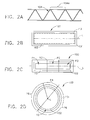
- the SMA actuation member 104 can be arranged in a substantially sinusoidal configuration.
- the sinusoidal configuration may comprise of SMA elements configured in a sinusoidal shape with substantially equally spaced sinuses (see 104A in Fig. 2B ).
- a substantially sinusoidal configuration having substantially irregularly spaced sinuses may also be possible (see 104B in Fig. 4B ).
- the substantially sinusoidal configuration may allow tailored control over one or more of the radial, axial and torsional pressures along the circumferential cross-section of the shape memory alloy mandrel 10.
- the sinusoidal configuration may allow for precise tailoring of specific levels of radial pressure and deflection at specific points of the cross section of the shape memory alloy mandrel 10.
- the sinusoidal configuration may also allow for the application of constant pressure via the SMA actuation member 104 even across a cross section which is non-uniform in shape (i.e. a complex shape).
- the SMA actuation member 104 may also provide different regions of pressure (i.e. non-uniform pressure) along the interior perimeter of the actuation shell 101 in a manner similar to that described above with respect to SMA fins 106.
- the different regions of pressure may be arranged axially about the longitudinal axis (i.e. about the circumference of the shape memory alloy mandrel 10).
- the different regions of pressure may be arranged perimetrically (i.e. over a portion of the circumference). It is noted that the SMA actuation member 104 may be trained to actuate under different temperatures or conditions compared to the SMA fins 106.
- the SMA fins 106 and SMA actuation member 104 may actuate sequentially (e.g., one before the other as opposed to simultaneously) as the temperature changes during the composite curing process.
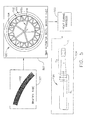
- Fig. 4 a diagram showing the design process for the SMA actuation member 104 is shown.
- Fig. 4 specifically shows the level of control over the degree and angle of the deflection of the SMA actuation member 104 which may be obtained by tailoring the substantially sinusoidal SMA member 104 to obtain a specific level of deflection and displacement between the phase transition process. As can be seen in Fig.
- a substantially sinusoidal SMA actuation member 104 in a first actuated state 401 and a second actuated state 402 are shown, as well as an overlay of the various actuated states 403.
- Fig. 4A an actuated form of the sinusoidal SMA actuation member 104 is shown.
- the SMA actuation member 104 may have a semi-irregular sinusoidal configuration 405 having substantially unequally spaced sinuses which may specifically tailor the deflection and pressure along the surface of the shape memory alloy actuation member 104.
- SMA actuators effects an interface pressure between the exterior contour of the SMA mandrel 10 and the structure to be cured and has a predetermined actuated shape that corresponds to a predetermined cured shape of the structure to be cured.
- the SMA actuation member 104 is disposed substantially around an inner surface 101a of an actuation shell 101.
- the actuation shell 101 may be a substantially rigid shield or form sharing the longitudinal axis L with the SMA mandrel 10 and the inner surface 101a extends along the longitudinal axis L.
- the actuation shell 101 may be made out of metal or any other suitable rigid material.
- the materials that form the actuation shell 101 may be rigid even under the high temperatures during the curing process of a composite structure.
- the materials that form the actuation shell 101 may also be any material which may be suitably rigid enough to withstand pressures during the curing process for the composite structure.
- the actuation shell 101 may also be comprised of an SMA material which may provide additional pressures during the composite curing process.
- the inner surface 101a may interface (e.g. substantially contact) with a composite structure 102 to be cured.
- the actuation shell 101 may have an inner surface 101a that provides a predetermined form or a shape for the composite structure 102 to take during the curing process.
- the shape memory alloy actuation member 104 and SMA fins 106 provide a radially outward pressure against the composite structure 102 so that the composite structure 102 presses against the inner perimeter 101a of the actuation shell 101 during the curing process where the composite structure 102 takes on the predetermined shape of the actuation shell 101 after curing.
- the actuation shell 101 may have a substantially circular cross section, as shown in Fig. 2 .
- the actuation shell 101 may take substantially any suitable form or shape (for example, see Fig. Figs. 4C-E for additional exemplary cross-sections of the actuation shell 101).
- the composite structure 102 to be cured may be positioned between the shape memory alloy actuation member 104 and the actuation shell 101 during the curing process.
- the shape memory alloy mandrel 10 has an outer boundary layer or first SMA shell 103 (shown in Fig. 3 ) of any suitable material (for example, SMA materials) between the SMA actuation member 104 and the composite structure 102 to provide for even distribution of pressure exerted by the SMA actuation member 104 during the curing process.
- the SMA actuation member 104 is disposed between and connected to the first SMA shell 103 and the second SMA shell 108.
- the outer boundary layer/first SMA shell 103 has an interior forming an interior space.
- the outer boundary layer/first SMA shell 103 may have a substantially non-uniform cross section in one or more of radial and longitudinal directions with respect to the longitudinal axis so as to form at multiple interior regions, for example a first interior region (R1) and second interior region (R2) (see, for instance, block 504 of Fig. 5 ).
- the outer boundary layer/first SMA shell 103 may take any suitable cross-section.
- Outer boundary layer/first SMA shell 103 may have any suitable configuration to allow the release of the composite structure 102 from the outer boundary layer/first SMA shell 103 and thus a release from the SMA mandrel 10.
- the outer boundary layer/first SMA shell 103 shares a longitudinal axis L with the SMA mandrel 10.
- the composite structure 102 may be any suitable structure which may be cured or formed by a mandrel.
- the composite structure 102 may be a braided composite structure which may be cured and shaped by the mandrel.
- the composite structure 102 may be any suitable material, for example, thermoplastics, resin structures, metal or any other material which may be shaped, formed or cured by a mandrel.
- compaction pressure may be exerted along a radial or axial direction upon the composite structure 102 by the SMA fins 106 and SMA actuation member 104.
- the exterior contour of the SMA mandrel 10 may have a predetermined actuated shape that corresponds to the predetermined cured shape of the composite structure 102.
- a SMA mandrel 10A of a compaction unit 100A is illustrated.
- the structures of Fig. 3 may substantially correspond to the structures shown in Fig. 2 .
- the SMA actuator mandrel 10 has a number of longitudinal SMA actuation members 109 in addition to SMA fins 106 and SMA actuation member 104.
- the longitudinal SMA actuation members 109 extend substantially along the longitudinal axis L and interface with the SMA actuation member 104 via the outer boundary layer/first SMA shell 103 and the composite structure 102 via a second boundary layer/boundary SMA shell 110.
- the outer boundary layer/first SMA shell 103 and boundary layer/boundary SMA shell 110 may allow for even distribution of radial and/or axial pressures during the deflection of the SMA actuation member 104 and the longitudinal SMA actuation members 109 during the curing process.
- the SMA actuators effects an interface pressure between the exterior contour of the second boundary layer/boundary SMA shell 110 and the composite structure 102 to be cured and has a predetermined actuated shape that corresponds to a predetermined cured shape of the composite structure 102 to be cured.
- the longitudinal SMA actuation members 109 may be attached or fixed to the boundary layer 103 and secondary boundary layer 110 to prevent shifting of the longitudinal SMA actuation members 109 and to better enable transfer of actuation pressure during the curing process.
- the longitudinal SMA actuation members 109 may also be arranged in an equally spaced and evenly distributed manner within the boundary layer 103 and boundary layer/boundary SMA shell 110.
- the longitudinal SMA actuation members 109 may be in the form of a plurality of SMA rods (see, for instance, SMA actuation member 109'), which may deflect in shape and position in addition to the SMA fins 106 and SMA actuation member 104 during the curing process.
- the longitudinal SMA actuation members 109 may allow for greater radial and/or axial expansion or deflection compared to the SMA mandrel 10 of Fig. 2 alone during the curing process.
- the longitudinal SMA actuation members 109 may also provide torsional forces that twist at least a portion of the composite structure 102.
- the longitudinal SMA actuation members 109 may also allow for greater transfer pressure to be placed on the composite structure 102 during the curing process.
- the longitudinal SMA actuation members 109 may also be trained with different parameters than those of SMA fins 106 and the SMA actuation member 104.
- the longitudinal SMA actuation members 109 may react to different conditions, for example, different temperatures from those of the SMA fins 106 and SMA actuation member 104. This may allow for sequential actuation of the SMA fins 106 (e.g., one before the other as opposed to simultaneously), SMA actuation member 104 and longitudinal SMA actuation members 109 at different temperatures at different points of the curing process.
- the sequential actuation of the various SMA components of the SMA actuator mandrel 10A may allow for more refined tailoring of actuation pressures during the curing process.
- individual longitudinal SMA actuation members 109 may be tailored to provide different actuation at different temperatures to further allow greater control over the curing and actuation process.
- the longitudinal SMA actuation members 109 may provide substantially uniform pressure one or more of an axial, radial and torsional direction against the interior perimeter surface 101a of the actuation shell 101.
- the longitudinal SMA actuation members 109 may also provide different regions of pressure (i.e. non-uniform pressure) along the interior perimeter of the actuation shell 101 in a manner similar to that described above.
- the different regions of pressure may be arranged axially about the longitudinal axis (i.e. about the circumference of the shape memory alloy mandrel 10A).
- the different regions of pressure may be arranged perimetrically in a manner similar to that described above..
- the longitudinal SMA actuation members 109 may be in the form of, for instance, SMA tubes or rods, as seen in Figs. 3 and 3A . In alternate aspects, the longitudinal SMA actuation members 109 may also take any suitable configurations or shapes. The longitudinal SMA actuation members 109 may exert pressure against the composite structure 102 and actuate along any suitable direction relative to the longitudinal axis L of the SMA mandrel 10A. Referring now to Figs. 3 and 3A , the longitudinal SMA actuation member 109 may have a substantially circular cross section as seen in longitudinal SMA actuation member 109'. However, referring now to Fig.
- the longitudinal SMA actuation member 109" may have a substantially arctuate (i.e. U-shaped) cross section.
- the substantially arctuate cross section of the longitudinal SMA actuation member 109" may allow for the exertion of pressure along the top surface 109A" of the arctuate cross section and the bottom surfaces 109B" to further tailor the points or regions at which the pressure is exerted on the composite structure 102.
- the longitudinal SMA actuation member 109" may have any suitable configuration.
- the SMA mandrel 10, 10A may have any suitable shape or form and the SMA actuation member 104, SMA fins 106 and longitudinal SMA actuation members 109 may also have any suitable shape.
- the SMA mandrel may include a hendecagonal actuation shell 101A and a pentagonal mandrel 10B.
- the SMA mandrel may have a substantially rectangular actuation shell 101B and a substantially rectangular mandrel 10C (see Fig. 4D ), or a square mandrel 10D and a square actuation shell 101C (see Fig. 4E ).
- the mandrels 10B-D and actuation shells 101A-C may be substantially similar to one or more of the mandrels 10, 10A and actuation shell 101.
- the mandrels 10B-D and actuation shells 101A-C may have any suitable shapes.
- the mandrels 10B-D may have a different shape than the actuation shells 101A-C.
- the hendecagonal actuation shell 101A may be utilized with a pentagonal mandrel 10B as shown in Fig. 4C .
- actuation shell 101A and mandrel 10B may facilitate further tailoring of pressure exerted on each part or region of the composite structure 102 positioned between the mandrel 10B and actuation shell 101A.
- Fig. 5 an exemplary flow diagram of a method of curing a composite structure is shown. The method is described with respect to SMA mandrel 10 as shown in Fig. 2 , but maybe similarly applied using the SMA mandrel 10A as well as the SMA mandrels shown in Figs. 4C-E .
- a braided tube or other composite structure 102 is provided in an uncured state.
- the composite structure 102 is placed inside actuation shell 101 and the SMA mandrel 10 may be placed inside the composite structure 102 to be formed. In other aspects, the composite structure 102 may be placed over the SMA mandrel 10 and then inserted into the actuation shell 101 as a unit.
- the SMA mandrel 10 may be substantially similar to the SMA mandrels 10, 10A as described above.
- heat is applied to the SMA mandrels 10 as part of the curing process.
- the heat in the curing process causes one or more of the SMA actuators (i.e. SMA fins 106, SMA actuation member 104 and longitudinal SMA actuation members 109) to be actuated.
- One or more of the SMA fins 106 and SMA actuation member 104 and longitudinal SMA actuation members 109 actuate to generate one or more of an axial, radial, and torsional pressure.
- the actuation of the SMA actuators of the SMA mandrel 10 may generate a substantially controlled generally outward radial pressure on the composite structure 102.
- the exterior contour of the SMA mandrel 10 may have a predetermined actuated shape that corresponds to the predetermined cured shape of the composite structure 102.
- the SMA fins 106, SMA actuation member 104 and longitudinal SMA actuation members 109 are tailored to generate substantially uniform pressure even along the different non-uniform points or regions of the actuation shells 101, 101A-C to further customize the curing of the composite structure.
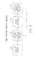
- FIG. 6 an exemplary flowchart for the tailoring of compaction pressures upon a composite structure 102 by SMA mandrels 10, 10A-D during the curing process is shown.
- the structural geometry of a composite structure surface to be made by the SMA mandrel is defined.
- the geometry of the composite structure is analyzed to identify the pressure(s) (and directions thereof) and temperature(s) needed for the curing process to form the composite structure.
- suitable SMA mandrel materials as well as a configuration of the SMA mandrel can be selected.
- This may include, for instance, the configuration of the geometry of the actuation shell 101, 101A-C, as well as the shape and configuration of the SMA mandrel 10, 10A (e.g. SMA fins 106, SMA actuation member 104 and longitudinal SMA actuation members 109) to provide the predetermined pressures for effecting the curing of composite structure 102.
- the actuation shell 101, 101A-C may have an interior contour that corresponds to the defined structural geometry of the composite structure.
- the SMA mandrel 10, 10A When actuated, may also an exterior contour that has a predetermined shape that corresponds to the defined structural geometry of the composite structure.
- the SMA actuators may be actuated at different times during the curing process.
- the actuation training process for the SMA actuators is defined. As the training process for the SMA actuator mandrel is being carried out, the testing of the SMA actuator mandrel may allow a return to block 602 to further identify pressure and temperatures for the curing process as the SMA actuator mandrel is iteratively improved during the training process.
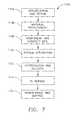
- Examples of the disclosure may be described in the context of an aircraft manufacturing and service method 1100 as shown in FIG. 7 and an aircraft 1102 as shown in FIG. 8 .
- the SMA actuator mandrels described herein may be employed, for instance, in any stage of aircraft manufacturing and the composite structures formed by the SMA actuator mandrels may form any suitable part of an aircraft or component used in aircraft design and manufacture.
- illustrative method 1100 may include specification and design 1104 of the aircraft 1102 and material procurement 1106.
- component and subassembly manufacturing 1108 and system integration 1110 of the aircraft 1102 take place.
- the SMA actuator mandrels described herein may be employed as part of the component and subassembly manufacturing process 1108.
- the SMA actuator mandrels may also be employed as part of the specification and design 1104 for the SMA actuator mandrel design process. Thereafter, the aircraft 1102 may go through certification and delivery 1112 to be placed in service 1114. While in service by a customer, the aircraft 1102 is scheduled for routine maintenance and service 1116 (which may also include modification, reconfiguration, refurbishment, and so on).
- Each of the processes of the illustrative method 1100 may be performed or carried out by a system integrator, a third party, and/or an operator (e.g., a customer).
- a system integrator may include, without limitation, any number of aircraft manufacturers and major-system subcontractors
- a third party may include, without limitation, any number of vendors, subcontractors, and suppliers
- an operator may be an airline, leasing company, military entity, service organization, and so on.
- the aircraft 1102 produced by the illustrative method 1100 may include an airframe 1118 with a plurality of high-level systems and an interior 1122.
- high-level systems include one or more of a propulsion system 1124, an electrical system 1126, a hydraulic system 1128, and an environmental system 1130.
- systems which may include composite components formed by an SMA mandrel may include propulsion system 1124, electrical system 1126, hydraulic system 1128 and environmental system 1130.
- an aerospace example is shown, the principles of the invention may be applied to other industries, such as the automotive and maritime industries.
- Apparatus and methods shown or described herein may be employed during any one or more of the stages of the manufacturing and service method 1100.
- components or subassemblies corresponding to component and subassembly manufacturing 1108 may be fabricated or manufactured in a manner similar to components or subassemblies produced while the aircraft 1102 is in service.
- one or more aspects of the apparatus, method, or combination thereof may be utilized during the production states 1108 and 1110, for example, by substantially expediting assembly of or reducing the cost of an aircraft 1102.
- one or more aspects of the apparatus or method realizations, or a combination thereof may be utilized, for example and without limitation, while the aircraft 1102 is in service, e.g., maintenance and service 1116.
- a mandrel having a shape memory alloy (SMA) shell having a longitudinal axis, an interior extending along the longitudinal axis and an exterior contour, the SMA shell being configured to interface with a structure to be cured, and at least one SMA actuation member disposed within the interior and connected to the SMA shell, where the at least one SMA actuation member is configured to exert pressure against the SMA shell effecting an interface pressure between the exterior contour of the SMA shell and the structure to be cured.
- SMA shape memory alloy
- the at least one SMA actuation member further comprises at least one SMA element arranged in a substantially sinusoidal configuration.
- the at least one SMA element may be arranged in a substantially sinusoidal configuration having unequally spaced sinuses.
- SMA actuation fins connected to the second SMA shell and being configured to effect an axial pressure, along the longitudinal axis, between the structure to be cured and the exterior contour of the SMA shell.
- an axially extending hub connected to the SMA actuation fins and being configured to stabilize the SMA actuation fins along the longitudinal axis
- At least one of the SMA actuation fins and the at least one SMA actuation member are configured to effect differing pressure regions against the SMA shell.
- the at least one SMA actuation member effects a radially outward pressure on the SMA shell.
- the at least one SMA actuation member is disposed around a perimeter of the SMA shell.
- the at least one SMA actuation member is configured to effect at least a first pressure region and a second pressure region where the pressure exerted against the SMA shell in the first pressure region is different than a pressure exerted against the SMA shell in the second pressure region.
- first and second pressure regions are arranged axially along the longitudinal axis.
- first and second pressure regions are arranged perimetrically about the longitudinal axis.
- the SMA shell has a substantially non-uniform cross section in one or more of radial and longitudinal directions with respect to the longitudinal axis so as to form at least a first interior region and a second interior region.
- the at least one SMA actuation member is configured to exert substantially the same pressure against the SMA shell in the first interior region and the second interior region.
- a mandrel having a first shape memory alloy (SMA) shell having a longitudinal axis, an exterior contour and forming an interior space, the exterior contour of the first SMA shell being configured to interface with a composite to be cured, and at least one SMA actuation member disposed within the interior space and being configured to effect regions of expansion pressure against the first SMA shell and effecting a transfer of expansion pressure to the composite to be cured.
- SMA shape memory alloy
- the regions comprise at least a first pressure region and second pressure region where the pressure exerted against the first SMA shell in the first pressure region is different than a pressure exerted against the first SMA shell in the second pressure region.
- the at least one SMA actuation member is configured to provide at least a radial and axial expansion pressure relative to the longitudinal axis.
- a boundary SMA shell disposed outward of the first SMA shell and at least one longitudinally extending SMA member disposed between and connecting the first SMA shell and the boundary SMA shell so as to transfer expansion pressure from the at least one SMA actuation member to the composite.
- the at least one longitudinally extending SMA member comprises a plurality of longitudinally extending SMA rods spaced about a circumference of the first SMA shell.
- the at least one longitudinally extending SMA member is configured to effect one or more of a torsional and bending force to the composite along the longitudinal axis.
- the at least one longitudinally extending SMA member is configured to have a substantially rod shape.
- the at least one longitudinally extending SMA member is configured to have a substantially arctuate shape.
- the at least one SMA actuation member comprises one or more of a circumferentially arranged SMA and a radially arranged SMA element.
- a method of forming a composite structure to be cured including placing the composite structure to be cured around a shape memory alloy (SMA) mandrel, and exerting a pressure against an SMA shell of the SMA mandrel so that the pressure is transferred to the composite structure to be cured by an exterior contoured surface of the SMA mandrel with at least one SMA member of the SMA mandrel.
- SMA shape memory alloy
- a method of tailoring pressure on a structure with a shape memory alloy (SMA) mandrel including defining a geometry of a composite structure to be cured during a curing process, identifying pressures and temperatures for the curing process for the composite structure, designing the SMA mandrel by matching the SMA mandrel with the identified pressures and temperatures where the SMA mandrel is contoured to a cured geometry of the composite structure, and assembling the SMA mandrel, placing the assembled SMA model within the composite structure to be cured so that a contoured exterior surface of the SMA mandrel is in contact with the composite structure, and curing the composite structure.
- SMA shape memory alloy
- a system for forming a composite structure having an actuation shell having an interior extending along a longitudinal axis and an interior contour, a shape memory alloy (SMA) shell having a longitudinal axis, an interior extending along the longitudinal axis and an exterior contour, the SMA shell being configured to interface with a composite structure to be cured, and at least one SMA actuation member disposed within the interior and connected to the SMA shell, where the at least one SMA actuation member is configured to exert pressure against the SMA shell effecting an interface pressure between the exterior contour of the SMA shell and the interior contour of the actuation shell to compress the composite structure for curing the composite structure and effecting a predetermined cured shape of the composite structure.
- SMA shape memory alloy
Landscapes
- Engineering & Computer Science (AREA)
- Mechanical Engineering (AREA)
- Chemical & Material Sciences (AREA)
- Composite Materials (AREA)
- Manufacturing & Machinery (AREA)
- Physics & Mathematics (AREA)
- Fluid Mechanics (AREA)
- General Chemical & Material Sciences (AREA)
- Chemical Kinetics & Catalysis (AREA)
- Materials Engineering (AREA)
- Metallurgy (AREA)
- Organic Chemistry (AREA)
- Moulding By Coating Moulds (AREA)
- Moulds For Moulding Plastics Or The Like (AREA)
- Casting Or Compression Moulding Of Plastics Or The Like (AREA)
- Laminated Bodies (AREA)
- Media Introduction/Drainage Providing Device (AREA)
Applications Claiming Priority (1)
| Application Number | Priority Date | Filing Date | Title |
|---|---|---|---|
| US14/340,914 US9919505B2 (en) | 2014-07-25 | 2014-07-25 | Apparatus and method for a shape memory alloy mandrel |
Publications (2)
| Publication Number | Publication Date |
|---|---|
| EP2977166A1 true EP2977166A1 (de) | 2016-01-27 |
| EP2977166B1 EP2977166B1 (de) | 2017-11-29 |
Family
ID=53488134
Family Applications (1)
| Application Number | Title | Priority Date | Filing Date |
|---|---|---|---|
| EP15170688.4A Active EP2977166B1 (de) | 2014-07-25 | 2015-06-04 | Einen formgedächtnis-legierungsdorn und ein verfahren zu seiner nutzung |
Country Status (5)
| Country | Link |
|---|---|
| US (1) | US9919505B2 (de) |
| EP (1) | EP2977166B1 (de) |
| JP (1) | JP6616978B2 (de) |
| CN (1) | CN105299026B (de) |
| RU (1) | RU2678547C2 (de) |
Cited By (1)
| Publication number | Priority date | Publication date | Assignee | Title |
|---|---|---|---|---|
| CN113264187A (zh) * | 2021-06-11 | 2021-08-17 | 中国空气动力研究与发展中心设备设计与测试技术研究所 | 空投软着陆的缓冲驱动装置设计方法及装置 |
Families Citing this family (11)
| Publication number | Priority date | Publication date | Assignee | Title |
|---|---|---|---|---|
| US9328695B2 (en) * | 2006-10-12 | 2016-05-03 | United Technologies Corporation | Variable fan nozzle using shape memory material |
| CA3281603A1 (en) | 2015-08-03 | 2025-11-29 | Angel Playing Cards Co., Ltd. | Management system for table games |
| US10053239B2 (en) * | 2015-09-09 | 2018-08-21 | The Boeing Company | Thermally graded adaptive multifunctional cellular structures with shape memory alloys |
| US20190202099A1 (en) * | 2018-01-03 | 2019-07-04 | Becton, Dickinson And Company | Shape-Memory Alloy Molding Parts |
| US10934021B2 (en) * | 2018-10-30 | 2021-03-02 | The Boeing Company | Shape memory alloy spacer system |
| WO2020130890A1 (en) * | 2018-12-17 | 2020-06-25 | Saab Ab | A mould body assembly and a method of forming a hollow article |
| CA3063886A1 (en) | 2019-08-16 | 2021-02-16 | Goodrich Corporation | Shape memory manufacturing for vessels |
| CN114962058B (zh) * | 2021-02-26 | 2025-07-15 | 中国航发商用航空发动机有限责任公司 | 尾喷管、航空发动机以及飞行器 |
| CN113370552B (zh) * | 2021-05-26 | 2021-12-14 | 南京航空航天大学 | 一种基于变曲率异形回转体的三维编织机离散化芯模系统 |
| US20230391025A1 (en) * | 2022-06-03 | 2023-12-07 | Rohr, Inc. | Smart materials to form nacelle core structure |
| CN116513442A (zh) * | 2023-05-10 | 2023-08-01 | 湖北三江航天红阳机电有限公司 | 一种壳体组件和飞行器 |
Citations (4)
| Publication number | Priority date | Publication date | Assignee | Title |
|---|---|---|---|---|
| JPS6176351A (ja) * | 1984-09-25 | 1986-04-18 | Toyota Motor Corp | 繊維強化樹脂構造体の製造方法 |
| JPS61215043A (ja) * | 1985-03-20 | 1986-09-24 | Sumitomo Electric Ind Ltd | 繊維強化プラスチツクスの成形法 |
| JPH04364929A (ja) * | 1991-06-13 | 1992-12-17 | Fuji Heavy Ind Ltd | 複合材の成形方法 |
| US20120118491A1 (en) * | 2010-11-11 | 2012-05-17 | Spirit Aerosystems, Inc. | Reconfigurable shape memory polymer tooling supports |
Family Cites Families (14)
| Publication number | Priority date | Publication date | Assignee | Title |
|---|---|---|---|---|
| JPS60139434A (ja) * | 1983-12-28 | 1985-07-24 | Toshiba Corp | 繊維強化プラスチツク成形型 |
| RU2050283C1 (ru) * | 1992-12-22 | 1995-12-20 | Андрей Вячеславович Артемьев | Способ формования изделий из композиционного материала |
| US5700337A (en) | 1996-03-01 | 1997-12-23 | Mcdonnell Douglas Corporation | Fabrication method for composite structure adapted for controlled structural deformation |
| US7422714B1 (en) * | 2001-01-24 | 2008-09-09 | Cornerstone Research Group, Inc. | Method of using a shape memory material as a mandrel for composite part manufacturing |
| RU2201343C2 (ru) * | 2001-05-29 | 2003-03-27 | Открытое акционерное общество Научно-производственное объединение "Искра" | Способ изготовления изделий из композиционных материалов |
| WO2003018853A2 (en) * | 2001-08-24 | 2003-03-06 | University Of Virginia Patent Foundation | Reversible shape memory multifunctional structural designs and method of using and making the same |
| US7093423B2 (en) * | 2004-01-20 | 2006-08-22 | General Electric Company | Methods and apparatus for operating gas turbine engines |
| US7550189B1 (en) * | 2004-08-13 | 2009-06-23 | Hrl Laboratories, Llc | Variable stiffness structure |
| GB0614114D0 (en) * | 2006-07-15 | 2006-08-23 | Rolls Royce Plc | An actuator |
| RU2329896C1 (ru) * | 2006-11-07 | 2008-07-27 | Государственное образовательное учреждение высшего профессионального образования Балтийский государственный технический университет "ВОЕНМЕХ" им. Д.Ф. Устинова (БГТУ "ВОЕНМЕХ") | Оправка для изготовления оболочек из композиционного материала |
| US8434293B2 (en) * | 2009-08-06 | 2013-05-07 | The Boeing Company | High stiffness shape memory alloy actuated aerostructure |
| RU2458791C2 (ru) * | 2010-08-05 | 2012-08-20 | Открытое Акционерное Общество "Московский машиностроительный экспериментальный завод - композиционные технологии" | Способ и оснастка для изготовления осесимметричных пустотелых оболочек (оболочек вращения) из полимерных композиционных материалов |
| KR101433120B1 (ko) * | 2010-08-20 | 2014-08-22 | 가부시키가이샤 세이덴샤 | 충격 구동형 액추에이터 |
| GB201116476D0 (en) * | 2011-09-26 | 2011-11-09 | Rolls Royce Plc | Mandrel for forming a component |
-
2014
- 2014-07-25 US US14/340,914 patent/US9919505B2/en active Active
-
2015
- 2015-05-14 RU RU2015118064A patent/RU2678547C2/ru active
- 2015-06-04 EP EP15170688.4A patent/EP2977166B1/de active Active
- 2015-07-23 JP JP2015145774A patent/JP6616978B2/ja active Active
- 2015-07-27 CN CN201510444721.6A patent/CN105299026B/zh active Active
Patent Citations (4)
| Publication number | Priority date | Publication date | Assignee | Title |
|---|---|---|---|---|
| JPS6176351A (ja) * | 1984-09-25 | 1986-04-18 | Toyota Motor Corp | 繊維強化樹脂構造体の製造方法 |
| JPS61215043A (ja) * | 1985-03-20 | 1986-09-24 | Sumitomo Electric Ind Ltd | 繊維強化プラスチツクスの成形法 |
| JPH04364929A (ja) * | 1991-06-13 | 1992-12-17 | Fuji Heavy Ind Ltd | 複合材の成形方法 |
| US20120118491A1 (en) * | 2010-11-11 | 2012-05-17 | Spirit Aerosystems, Inc. | Reconfigurable shape memory polymer tooling supports |
Cited By (1)
| Publication number | Priority date | Publication date | Assignee | Title |
|---|---|---|---|---|
| CN113264187A (zh) * | 2021-06-11 | 2021-08-17 | 中国空气动力研究与发展中心设备设计与测试技术研究所 | 空投软着陆的缓冲驱动装置设计方法及装置 |
Also Published As
| Publication number | Publication date |
|---|---|
| CN105299026B (zh) | 2019-11-29 |
| US9919505B2 (en) | 2018-03-20 |
| JP2016030443A (ja) | 2016-03-07 |
| EP2977166B1 (de) | 2017-11-29 |
| CN105299026A (zh) | 2016-02-03 |
| US20160023406A1 (en) | 2016-01-28 |
| RU2678547C2 (ru) | 2019-01-29 |
| RU2015118064A (ru) | 2016-12-10 |
| RU2015118064A3 (de) | 2018-06-05 |
| JP6616978B2 (ja) | 2019-12-04 |
Similar Documents
| Publication | Publication Date | Title |
|---|---|---|
| EP2977166B1 (de) | Einen formgedächtnis-legierungsdorn und ein verfahren zu seiner nutzung | |
| EP3208068B1 (de) | Vorrichtung zur induktionserwärmung und biegung von thermoplastischen verbundrohren und verfahren zur verwendung davon | |
| US10774858B2 (en) | Assemblies including shape memory alloy fittings and composite structural members | |
| US11400620B2 (en) | Methods and apparatus for curing composite nacelle structure | |
| CN103286961B (zh) | 在封闭腔模具中制造复合构件的系统和方法 | |
| US11091847B2 (en) | Method of manufacturing aircraft engine parts utilizing reusable and reconfigurable smart memory polymer mandrel | |
| TWI862676B (zh) | 產生應用在拉壓桿之正鎖定載重的方法及拉壓桿 | |
| US20120090770A1 (en) | Method for making composite parts having complex shapes | |
| GHANADI et al. | A thermoelasticity solution for thick cylinders subjected to thermo-mechanical loads under various boundary conditions | |
| Daneshjou et al. | Transient thermal analysis in 2D orthotropic FG hollow cylinder with heat source | |
| Hashemi et al. | Numerical and experimental investigation of temperature effect on thickness distribution in warm hydroforming of aluminum tubes | |
| Panicker et al. | Improvement in material flow during nonisothermal warm deep drawing of nonheat treatable aluminum alloy sheets | |
| US10815936B2 (en) | Flexible bearing assemblies, rocket motors including such assemblies, and methods of forming flexible bearings | |
| Kanttikar et al. | Analysis on deformation process in deep drawing of sheet metal part by FEM | |
| Jin et al. | A modified isotropic–kinematic hardening model to predict the defects in tube hydroforming process | |
| Chalasani et al. | Enhancement of thrust vector control by composite reinforcements in conical elastomeric bearing | |
| Elyasi et al. | A new die design for the hydroforming of stepped tubes | |
| Thuis | Composite landing gear components for aerospace applications | |
| Pagel et al. | Development of design principles for SMA wave springs | |
| RU2819679C1 (ru) | Способ создания приложения нагрузки с принудительной блокировкой для стержня растяжения-сжатия и соответствующий стержень | |
| US20190061291A1 (en) | Methods of forming a cored composite laminate | |
| DE102012002841A1 (de) | Vorrichtung und Verfahren zum Herstellen eines gekrümmten Rohrs aus faserverstärktem Verbundkunststoff | |
| RU18246U1 (ru) | Индуктор для деформирования трубчатой заготовки энергией импульсного магнитного поля | |
| Hall et al. | Hollow Sections—How to Make Composite Tubes | |
| Safari | Laser forming of metallic dome-shaped parts using spiral and radial-circular scan paths |
Legal Events
| Date | Code | Title | Description |
|---|---|---|---|
| PUAI | Public reference made under article 153(3) epc to a published international application that has entered the european phase |
Free format text: ORIGINAL CODE: 0009012 |
|
| 17P | Request for examination filed |
Effective date: 20150604 |
|
| AK | Designated contracting states |
Kind code of ref document: A1 Designated state(s): AL AT BE BG CH CY CZ DE DK EE ES FI FR GB GR HR HU IE IS IT LI LT LU LV MC MK MT NL NO PL PT RO RS SE SI SK SM TR |
|
| AX | Request for extension of the european patent |
Extension state: BA ME |
|
| GRAP | Despatch of communication of intention to grant a patent |
Free format text: ORIGINAL CODE: EPIDOSNIGR1 |
|
| RIC1 | Information provided on ipc code assigned before grant |
Ipc: B29C 70/54 20060101ALN20170623BHEP Ipc: B29C 33/38 20060101AFI20170623BHEP Ipc: B29C 70/32 20060101ALN20170623BHEP Ipc: B29C 33/48 20060101ALI20170623BHEP |
|
| INTG | Intention to grant announced |
Effective date: 20170717 |
|
| GRAS | Grant fee paid |
Free format text: ORIGINAL CODE: EPIDOSNIGR3 |
|
| GRAA | (expected) grant |
Free format text: ORIGINAL CODE: 0009210 |
|
| AK | Designated contracting states |
Kind code of ref document: B1 Designated state(s): AL AT BE BG CH CY CZ DE DK EE ES FI FR GB GR HR HU IE IS IT LI LT LU LV MC MK MT NL NO PL PT RO RS SE SI SK SM TR |
|
| REG | Reference to a national code |
Ref country code: CH Ref legal event code: EP |
|
| REG | Reference to a national code |
Ref country code: AT Ref legal event code: REF Ref document number: 949980 Country of ref document: AT Kind code of ref document: T Effective date: 20171215 |
|
| REG | Reference to a national code |
Ref country code: IE Ref legal event code: FG4D |
|
| REG | Reference to a national code |
Ref country code: DE Ref legal event code: R096 Ref document number: 602015006276 Country of ref document: DE |
|
| REG | Reference to a national code |
Ref country code: NL Ref legal event code: MP Effective date: 20171129 |
|
| REG | Reference to a national code |
Ref country code: LT Ref legal event code: MG4D |
|
| REG | Reference to a national code |
Ref country code: AT Ref legal event code: MK05 Ref document number: 949980 Country of ref document: AT Kind code of ref document: T Effective date: 20171129 |
|
| PG25 | Lapsed in a contracting state [announced via postgrant information from national office to epo] |
Ref country code: FI Free format text: LAPSE BECAUSE OF FAILURE TO SUBMIT A TRANSLATION OF THE DESCRIPTION OR TO PAY THE FEE WITHIN THE PRESCRIBED TIME-LIMIT Effective date: 20171129 Ref country code: NO Free format text: LAPSE BECAUSE OF FAILURE TO SUBMIT A TRANSLATION OF THE DESCRIPTION OR TO PAY THE FEE WITHIN THE PRESCRIBED TIME-LIMIT Effective date: 20180228 Ref country code: ES Free format text: LAPSE BECAUSE OF FAILURE TO SUBMIT A TRANSLATION OF THE DESCRIPTION OR TO PAY THE FEE WITHIN THE PRESCRIBED TIME-LIMIT Effective date: 20171129 Ref country code: SE Free format text: LAPSE BECAUSE OF FAILURE TO SUBMIT A TRANSLATION OF THE DESCRIPTION OR TO PAY THE FEE WITHIN THE PRESCRIBED TIME-LIMIT Effective date: 20171129 Ref country code: LT Free format text: LAPSE BECAUSE OF FAILURE TO SUBMIT A TRANSLATION OF THE DESCRIPTION OR TO PAY THE FEE WITHIN THE PRESCRIBED TIME-LIMIT Effective date: 20171129 |
|
| PG25 | Lapsed in a contracting state [announced via postgrant information from national office to epo] |
Ref country code: HR Free format text: LAPSE BECAUSE OF FAILURE TO SUBMIT A TRANSLATION OF THE DESCRIPTION OR TO PAY THE FEE WITHIN THE PRESCRIBED TIME-LIMIT Effective date: 20171129 Ref country code: LV Free format text: LAPSE BECAUSE OF FAILURE TO SUBMIT A TRANSLATION OF THE DESCRIPTION OR TO PAY THE FEE WITHIN THE PRESCRIBED TIME-LIMIT Effective date: 20171129 Ref country code: RS Free format text: LAPSE BECAUSE OF FAILURE TO SUBMIT A TRANSLATION OF THE DESCRIPTION OR TO PAY THE FEE WITHIN THE PRESCRIBED TIME-LIMIT Effective date: 20171129 Ref country code: AT Free format text: LAPSE BECAUSE OF FAILURE TO SUBMIT A TRANSLATION OF THE DESCRIPTION OR TO PAY THE FEE WITHIN THE PRESCRIBED TIME-LIMIT Effective date: 20171129 Ref country code: GR Free format text: LAPSE BECAUSE OF FAILURE TO SUBMIT A TRANSLATION OF THE DESCRIPTION OR TO PAY THE FEE WITHIN THE PRESCRIBED TIME-LIMIT Effective date: 20180301 Ref country code: BG Free format text: LAPSE BECAUSE OF FAILURE TO SUBMIT A TRANSLATION OF THE DESCRIPTION OR TO PAY THE FEE WITHIN THE PRESCRIBED TIME-LIMIT Effective date: 20180228 |
|
| REG | Reference to a national code |
Ref country code: FR Ref legal event code: PLFP Year of fee payment: 4 |
|
| PG25 | Lapsed in a contracting state [announced via postgrant information from national office to epo] |
Ref country code: NL Free format text: LAPSE BECAUSE OF FAILURE TO SUBMIT A TRANSLATION OF THE DESCRIPTION OR TO PAY THE FEE WITHIN THE PRESCRIBED TIME-LIMIT Effective date: 20171129 |
|
| PG25 | Lapsed in a contracting state [announced via postgrant information from national office to epo] |
Ref country code: SK Free format text: LAPSE BECAUSE OF FAILURE TO SUBMIT A TRANSLATION OF THE DESCRIPTION OR TO PAY THE FEE WITHIN THE PRESCRIBED TIME-LIMIT Effective date: 20171129 Ref country code: CZ Free format text: LAPSE BECAUSE OF FAILURE TO SUBMIT A TRANSLATION OF THE DESCRIPTION OR TO PAY THE FEE WITHIN THE PRESCRIBED TIME-LIMIT Effective date: 20171129 Ref country code: EE Free format text: LAPSE BECAUSE OF FAILURE TO SUBMIT A TRANSLATION OF THE DESCRIPTION OR TO PAY THE FEE WITHIN THE PRESCRIBED TIME-LIMIT Effective date: 20171129 Ref country code: CY Free format text: LAPSE BECAUSE OF FAILURE TO SUBMIT A TRANSLATION OF THE DESCRIPTION OR TO PAY THE FEE WITHIN THE PRESCRIBED TIME-LIMIT Effective date: 20171129 Ref country code: DK Free format text: LAPSE BECAUSE OF FAILURE TO SUBMIT A TRANSLATION OF THE DESCRIPTION OR TO PAY THE FEE WITHIN THE PRESCRIBED TIME-LIMIT Effective date: 20171129 |
|
| REG | Reference to a national code |
Ref country code: DE Ref legal event code: R097 Ref document number: 602015006276 Country of ref document: DE |
|
| PG25 | Lapsed in a contracting state [announced via postgrant information from national office to epo] |
Ref country code: RO Free format text: LAPSE BECAUSE OF FAILURE TO SUBMIT A TRANSLATION OF THE DESCRIPTION OR TO PAY THE FEE WITHIN THE PRESCRIBED TIME-LIMIT Effective date: 20171129 Ref country code: PL Free format text: LAPSE BECAUSE OF FAILURE TO SUBMIT A TRANSLATION OF THE DESCRIPTION OR TO PAY THE FEE WITHIN THE PRESCRIBED TIME-LIMIT Effective date: 20171129 Ref country code: SM Free format text: LAPSE BECAUSE OF FAILURE TO SUBMIT A TRANSLATION OF THE DESCRIPTION OR TO PAY THE FEE WITHIN THE PRESCRIBED TIME-LIMIT Effective date: 20171129 Ref country code: IT Free format text: LAPSE BECAUSE OF FAILURE TO SUBMIT A TRANSLATION OF THE DESCRIPTION OR TO PAY THE FEE WITHIN THE PRESCRIBED TIME-LIMIT Effective date: 20171129 |
|
| PLBE | No opposition filed within time limit |
Free format text: ORIGINAL CODE: 0009261 |
|
| STAA | Information on the status of an ep patent application or granted ep patent |
Free format text: STATUS: NO OPPOSITION FILED WITHIN TIME LIMIT |
|
| 26N | No opposition filed |
Effective date: 20180830 |
|
| PG25 | Lapsed in a contracting state [announced via postgrant information from national office to epo] |
Ref country code: SI Free format text: LAPSE BECAUSE OF FAILURE TO SUBMIT A TRANSLATION OF THE DESCRIPTION OR TO PAY THE FEE WITHIN THE PRESCRIBED TIME-LIMIT Effective date: 20171129 |
|
| REG | Reference to a national code |
Ref country code: CH Ref legal event code: PL |
|
| REG | Reference to a national code |
Ref country code: BE Ref legal event code: MM Effective date: 20180630 |
|
| REG | Reference to a national code |
Ref country code: IE Ref legal event code: MM4A |
|
| PG25 | Lapsed in a contracting state [announced via postgrant information from national office to epo] |
Ref country code: LU Free format text: LAPSE BECAUSE OF NON-PAYMENT OF DUE FEES Effective date: 20180604 Ref country code: MC Free format text: LAPSE BECAUSE OF FAILURE TO SUBMIT A TRANSLATION OF THE DESCRIPTION OR TO PAY THE FEE WITHIN THE PRESCRIBED TIME-LIMIT Effective date: 20171129 |
|
| PG25 | Lapsed in a contracting state [announced via postgrant information from national office to epo] |
Ref country code: CH Free format text: LAPSE BECAUSE OF NON-PAYMENT OF DUE FEES Effective date: 20180630 Ref country code: LI Free format text: LAPSE BECAUSE OF NON-PAYMENT OF DUE FEES Effective date: 20180630 Ref country code: IE Free format text: LAPSE BECAUSE OF NON-PAYMENT OF DUE FEES Effective date: 20180604 |
|
| PG25 | Lapsed in a contracting state [announced via postgrant information from national office to epo] |
Ref country code: BE Free format text: LAPSE BECAUSE OF NON-PAYMENT OF DUE FEES Effective date: 20180630 |
|
| PG25 | Lapsed in a contracting state [announced via postgrant information from national office to epo] |
Ref country code: MT Free format text: LAPSE BECAUSE OF NON-PAYMENT OF DUE FEES Effective date: 20180604 |
|
| PG25 | Lapsed in a contracting state [announced via postgrant information from national office to epo] |
Ref country code: TR Free format text: LAPSE BECAUSE OF FAILURE TO SUBMIT A TRANSLATION OF THE DESCRIPTION OR TO PAY THE FEE WITHIN THE PRESCRIBED TIME-LIMIT Effective date: 20171129 |
|
| PG25 | Lapsed in a contracting state [announced via postgrant information from national office to epo] |
Ref country code: PT Free format text: LAPSE BECAUSE OF FAILURE TO SUBMIT A TRANSLATION OF THE DESCRIPTION OR TO PAY THE FEE WITHIN THE PRESCRIBED TIME-LIMIT Effective date: 20171129 |
|
| PG25 | Lapsed in a contracting state [announced via postgrant information from national office to epo] |
Ref country code: MK Free format text: LAPSE BECAUSE OF NON-PAYMENT OF DUE FEES Effective date: 20171129 Ref country code: HU Free format text: LAPSE BECAUSE OF FAILURE TO SUBMIT A TRANSLATION OF THE DESCRIPTION OR TO PAY THE FEE WITHIN THE PRESCRIBED TIME-LIMIT; INVALID AB INITIO Effective date: 20150604 |
|
| PG25 | Lapsed in a contracting state [announced via postgrant information from national office to epo] |
Ref country code: AL Free format text: LAPSE BECAUSE OF FAILURE TO SUBMIT A TRANSLATION OF THE DESCRIPTION OR TO PAY THE FEE WITHIN THE PRESCRIBED TIME-LIMIT Effective date: 20171129 Ref country code: IS Free format text: LAPSE BECAUSE OF FAILURE TO SUBMIT A TRANSLATION OF THE DESCRIPTION OR TO PAY THE FEE WITHIN THE PRESCRIBED TIME-LIMIT Effective date: 20180329 |
|
| P01 | Opt-out of the competence of the unified patent court (upc) registered |
Effective date: 20230516 |
|
| PGFP | Annual fee paid to national office [announced via postgrant information from national office to epo] |
Ref country code: GB Payment date: 20260629 Year of fee payment: 12 |
|
| PGFP | Annual fee paid to national office [announced via postgrant information from national office to epo] |
Ref country code: DE Payment date: 20260629 Year of fee payment: 12 |
|
| PGFP | Annual fee paid to national office [announced via postgrant information from national office to epo] |
Ref country code: FR Payment date: 20260625 Year of fee payment: 12 |