US10815936B2 - Flexible bearing assemblies, rocket motors including such assemblies, and methods of forming flexible bearings - Google Patents
Flexible bearing assemblies, rocket motors including such assemblies, and methods of forming flexible bearings Download PDFInfo
- Publication number
- US10815936B2 US10815936B2 US15/347,621 US201615347621A US10815936B2 US 10815936 B2 US10815936 B2 US 10815936B2 US 201615347621 A US201615347621 A US 201615347621A US 10815936 B2 US10815936 B2 US 10815936B2
- Authority
- US
- United States
- Prior art keywords
- end ring
- flexible bearing
- metal end
- layers
- bearing core
- Prior art date
- Legal status (The legal status is an assumption and is not a legal conclusion. Google has not performed a legal analysis and makes no representation as to the accuracy of the status listed.)
- Active, expires
Links
- 238000000034 method Methods 0.000 title claims abstract description 28
- 230000000712 assembly Effects 0.000 title description 20
- 238000000429 assembly Methods 0.000 title description 20
- 239000002131 composite material Substances 0.000 claims abstract description 55
- ISWSIDIOOBJBQZ-UHFFFAOYSA-N phenol group Chemical group C1(=CC=CC=C1)O ISWSIDIOOBJBQZ-UHFFFAOYSA-N 0.000 claims abstract description 53
- 239000000463 material Substances 0.000 claims abstract description 52
- 239000012858 resilient material Substances 0.000 claims abstract description 44
- 239000002184 metal Substances 0.000 claims abstract description 41
- 230000002787 reinforcement Effects 0.000 claims abstract description 33
- 239000003380 propellant Substances 0.000 claims abstract description 9
- 239000000853 adhesive Substances 0.000 claims description 12
- 230000001070 adhesive effect Effects 0.000 claims description 12
- 230000005855 radiation Effects 0.000 claims description 6
- KXGFMDJXCMQABM-UHFFFAOYSA-N 2-methoxy-6-methylphenol Chemical compound [CH]OC1=CC=CC([CH])=C1O KXGFMDJXCMQABM-UHFFFAOYSA-N 0.000 claims description 3
- 229920000049 Carbon (fiber) Polymers 0.000 claims description 3
- 239000004917 carbon fiber Substances 0.000 claims description 3
- 229920001971 elastomer Polymers 0.000 claims description 3
- 239000000806 elastomer Substances 0.000 claims description 3
- 239000011521 glass Substances 0.000 claims description 3
- 229920001568 phenolic resin Polymers 0.000 claims description 3
- 239000005011 phenolic resin Substances 0.000 claims description 3
- 239000004449 solid propellant Substances 0.000 claims description 3
- 229910000831 Steel Inorganic materials 0.000 claims description 2
- 239000010959 steel Substances 0.000 claims description 2
- 230000008878 coupling Effects 0.000 claims 1
- 238000010168 coupling process Methods 0.000 claims 1
- 238000005859 coupling reaction Methods 0.000 claims 1
- 238000004132 cross linking Methods 0.000 claims 1
- 238000004519 manufacturing process Methods 0.000 description 7
- 238000003475 lamination Methods 0.000 description 5
- 238000007796 conventional method Methods 0.000 description 4
- 238000013461 design Methods 0.000 description 2
- 239000013536 elastomeric material Substances 0.000 description 2
- 238000011156 evaluation Methods 0.000 description 2
- 238000010438 heat treatment Methods 0.000 description 2
- 238000007689 inspection Methods 0.000 description 2
- 229920001296 polysiloxane Polymers 0.000 description 2
- -1 polysiloxane chains Polymers 0.000 description 2
- 239000002243 precursor Substances 0.000 description 2
- 238000012360 testing method Methods 0.000 description 2
- 238000007792 addition Methods 0.000 description 1
- 238000001816 cooling Methods 0.000 description 1
- 230000007547 defect Effects 0.000 description 1
- 238000012217 deletion Methods 0.000 description 1
- 230000037430 deletion Effects 0.000 description 1
- 230000001066 destructive effect Effects 0.000 description 1
- 239000004744 fabric Substances 0.000 description 1
- 239000007789 gas Substances 0.000 description 1
- 239000007788 liquid Substances 0.000 description 1
- 238000005259 measurement Methods 0.000 description 1
- 239000007769 metal material Substances 0.000 description 1
- 239000000203 mixture Substances 0.000 description 1
- 238000012986 modification Methods 0.000 description 1
- 230000004048 modification Effects 0.000 description 1
- 238000000465 moulding Methods 0.000 description 1
- 239000002952 polymeric resin Substances 0.000 description 1
- 238000012545 processing Methods 0.000 description 1
- 229920003002 synthetic resin Polymers 0.000 description 1
Images


Classifications
-
- F—MECHANICAL ENGINEERING; LIGHTING; HEATING; WEAPONS; BLASTING
- F02—COMBUSTION ENGINES; HOT-GAS OR COMBUSTION-PRODUCT ENGINE PLANTS
- F02K—JET-PROPULSION PLANTS
- F02K9/00—Rocket-engine plants, i.e. plants carrying both fuel and oxidant therefor; Control thereof
- F02K9/80—Rocket-engine plants, i.e. plants carrying both fuel and oxidant therefor; Control thereof characterised by thrust or thrust vector control
- F02K9/86—Rocket-engine plants, i.e. plants carrying both fuel and oxidant therefor; Control thereof characterised by thrust or thrust vector control using nozzle throats of adjustable cross- section
-
- B—PERFORMING OPERATIONS; TRANSPORTING
- B29—WORKING OF PLASTICS; WORKING OF SUBSTANCES IN A PLASTIC STATE IN GENERAL
- B29C—SHAPING OR JOINING OF PLASTICS; SHAPING OF MATERIAL IN A PLASTIC STATE, NOT OTHERWISE PROVIDED FOR; AFTER-TREATMENT OF THE SHAPED PRODUCTS, e.g. REPAIRING
- B29C65/00—Joining or sealing of preformed parts, e.g. welding of plastics materials; Apparatus therefor
- B29C65/02—Joining or sealing of preformed parts, e.g. welding of plastics materials; Apparatus therefor by heating, with or without pressure
- B29C65/14—Joining or sealing of preformed parts, e.g. welding of plastics materials; Apparatus therefor by heating, with or without pressure using wave energy, i.e. electromagnetic radiation, or particle radiation
- B29C65/1403—Joining or sealing of preformed parts, e.g. welding of plastics materials; Apparatus therefor by heating, with or without pressure using wave energy, i.e. electromagnetic radiation, or particle radiation characterised by the type of electromagnetic or particle radiation
-
- B—PERFORMING OPERATIONS; TRANSPORTING
- B29—WORKING OF PLASTICS; WORKING OF SUBSTANCES IN A PLASTIC STATE IN GENERAL
- B29C—SHAPING OR JOINING OF PLASTICS; SHAPING OF MATERIAL IN A PLASTIC STATE, NOT OTHERWISE PROVIDED FOR; AFTER-TREATMENT OF THE SHAPED PRODUCTS, e.g. REPAIRING
- B29C65/00—Joining or sealing of preformed parts, e.g. welding of plastics materials; Apparatus therefor
- B29C65/48—Joining or sealing of preformed parts, e.g. welding of plastics materials; Apparatus therefor using adhesives, i.e. using supplementary joining material; solvent bonding
-
- F—MECHANICAL ENGINEERING; LIGHTING; HEATING; WEAPONS; BLASTING
- F02—COMBUSTION ENGINES; HOT-GAS OR COMBUSTION-PRODUCT ENGINE PLANTS
- F02K—JET-PROPULSION PLANTS
- F02K9/00—Rocket-engine plants, i.e. plants carrying both fuel and oxidant therefor; Control thereof
- F02K9/08—Rocket-engine plants, i.e. plants carrying both fuel and oxidant therefor; Control thereof using solid propellants
- F02K9/32—Constructional parts; Details not otherwise provided for
- F02K9/34—Casings; Combustion chambers; Liners thereof
- F02K9/343—Joints, connections, seals therefor
-
- F—MECHANICAL ENGINEERING; LIGHTING; HEATING; WEAPONS; BLASTING
- F02—COMBUSTION ENGINES; HOT-GAS OR COMBUSTION-PRODUCT ENGINE PLANTS
- F02K—JET-PROPULSION PLANTS
- F02K9/00—Rocket-engine plants, i.e. plants carrying both fuel and oxidant therefor; Control thereof
- F02K9/80—Rocket-engine plants, i.e. plants carrying both fuel and oxidant therefor; Control thereof characterised by thrust or thrust vector control
- F02K9/84—Rocket-engine plants, i.e. plants carrying both fuel and oxidant therefor; Control thereof characterised by thrust or thrust vector control using movable nozzles
-
- F—MECHANICAL ENGINEERING; LIGHTING; HEATING; WEAPONS; BLASTING
- F02—COMBUSTION ENGINES; HOT-GAS OR COMBUSTION-PRODUCT ENGINE PLANTS
- F02K—JET-PROPULSION PLANTS
- F02K9/00—Rocket-engine plants, i.e. plants carrying both fuel and oxidant therefor; Control thereof
- F02K9/97—Rocket nozzles
-
- F—MECHANICAL ENGINEERING; LIGHTING; HEATING; WEAPONS; BLASTING
- F02—COMBUSTION ENGINES; HOT-GAS OR COMBUSTION-PRODUCT ENGINE PLANTS
- F02K—JET-PROPULSION PLANTS
- F02K9/00—Rocket-engine plants, i.e. plants carrying both fuel and oxidant therefor; Control thereof
- F02K9/97—Rocket nozzles
- F02K9/978—Closures for nozzles; Nozzles comprising ejectable or discardable elements
-
- B—PERFORMING OPERATIONS; TRANSPORTING
- B29—WORKING OF PLASTICS; WORKING OF SUBSTANCES IN A PLASTIC STATE IN GENERAL
- B29L—INDEXING SCHEME ASSOCIATED WITH SUBCLASS B29C, RELATING TO PARTICULAR ARTICLES
- B29L2031/00—Other particular articles
- B29L2031/04—Bearings
-
- F—MECHANICAL ENGINEERING; LIGHTING; HEATING; WEAPONS; BLASTING
- F05—INDEXING SCHEMES RELATING TO ENGINES OR PUMPS IN VARIOUS SUBCLASSES OF CLASSES F01-F04
- F05D—INDEXING SCHEME FOR ASPECTS RELATING TO NON-POSITIVE-DISPLACEMENT MACHINES OR ENGINES, GAS-TURBINES OR JET-PROPULSION PLANTS
- F05D2230/00—Manufacture
- F05D2230/20—Manufacture essentially without removing material
- F05D2230/23—Manufacture essentially without removing material by permanently joining parts together
-
- F—MECHANICAL ENGINEERING; LIGHTING; HEATING; WEAPONS; BLASTING
- F05—INDEXING SCHEMES RELATING TO ENGINES OR PUMPS IN VARIOUS SUBCLASSES OF CLASSES F01-F04
- F05D—INDEXING SCHEME FOR ASPECTS RELATING TO NON-POSITIVE-DISPLACEMENT MACHINES OR ENGINES, GAS-TURBINES OR JET-PROPULSION PLANTS
- F05D2240/00—Components
- F05D2240/50—Bearings
Definitions
- Embodiments of the present disclosure relate generally to flexible bearing assemblies, to rocket motors including such bearing assemblies, and to methods of forming flexible bearings.
- Rocket motor assemblies generally include at least one containment vessel (e.g., a housing) having at least one propellant structure (e.g., a solid propellant grain) therein, and at least one thrust nozzle operatively associated with the containment vessel.
- a containment vessel e.g., a housing
- propellant structure e.g., a solid propellant grain
- Rocket motor assemblies can also include flexible bearing assemblies operatively associated with the thrust nozzles thereof.
- a flexible bearing assembly may include a lamination of alternating flexible seals and rigid shims stacked and bonded together. Both the top and bottom layers may be an elastomer, and the lamination is positioned between and bonded to metallic end rings. One end ring may comprise the thrust nozzle ring of a rocket motor, and the other may comprise the rocket case mounting ring.
- the lamination may be laterally flexible, that is, in directions parallel to the layers.
- the lamination may have some axial flexibility (in the directions perpendicular to the layers), but preferably is stiffer in the axial direction than the lateral direction.
- Lateral movement of the flexible bearing assembly may be used to modify the orientation of the thrust nozzle operatively associated therewith, so as to control the direction of the rocket motor assembly during use and operation (e.g., flight) of the rocket motor assembly.
- Conventional flexible bearing assemblies are formed by heating and curing elastomeric material between the metallic end rings and the shims. Once the elastomeric material is cured, it provides material properties to allow the flexible bearing assembly to operate as described above. Bench testing may be used to verify proper movement of the flexible bearing assembly.
- a flexible bearing assembly includes at least one metal end ring, a flexible bearing core having a plurality of layers of a resilient material between layers of a reinforcement material, and a phenolic composite material between and bonded to each of the at least one metal end ring and the flexible bearing core.
- a rocket motor assembly includes a chamber configured to contain a propellant and a movable thrust nozzle coupled to the chamber.
- the movable thrust nozzle includes at least one metal end ring, a flexible bearing core having a plurality of layers of a resilient material between layers of a reinforcement material, and a phenolic composite material between and bonded to each of the at least one metal end ring and the flexible bearing core.
- Methods of forming a flexible bearing assembly include bonding a phenolic composite material to at least one metal end ring and bonding a flexible bearing core to the phenolic composite material.
- the flexible bearing core includes a plurality of layers of a resilient material between layers of a reinforcement material.
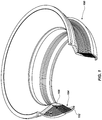
- FIG. 1 is a simplified cut-away perspective view of a movable thrust nozzle including a flexible bearing assembly in accordance with an embodiment of the disclosure.
- FIG. 2 is an expanded view showing a portion of the nozzle assembly of FIG. 1 in more detail.
- FIG. 3 is a partial cross-sectional view of another nozzle including a flexible bearing assembly according to an embodiment of the disclosure.
- FIG. 4 is a simplified schematic view of a rocket motor assembly including a nozzle having a flexible bearing assembly according to an embodiment of the disclosure.
- the terms “comprising,” “including,” “containing,” “characterized by,” and grammatical equivalents thereof are inclusive or open-ended terms that do not exclude additional, unrecited elements or method steps, but also include the more restrictive terms “consisting of” and “consisting essentially of” and grammatical equivalents thereof.
- the term “may” with respect to a material, structure, feature or method act indicates that such is contemplated for use in implementation of an embodiment of the disclosure and such term is used in preference to the more restrictive term “is” so as to avoid any implication that other, compatible materials, structures, features and methods usable in combination therewith should or must be excluded.
- the term “configured” refers to a size, shape, material composition, and arrangement of one or more of at least one structure and at least one apparatus facilitating operation of one or more of the structure and the apparatus in a predetermined way.
- spatially relative terms such as “beneath,” “below,” “lower,” “bottom,” “above,” “upper,” “top,” “front,” “rear,” “left,” “right,” and the like, may be used for ease of description to describe one element's or feature's relationship to another element(s) or feature(s) as illustrated in the figures.
- the spatially relative terms are intended to encompass different orientations of the materials in addition to the orientation depicted in the figures. For example, if materials in the figures are inverted, elements described as “below” or “beneath” or “under” or “on bottom of” other elements or features would then be oriented “above” or “on top of” the other elements or features.
- the term “below” can encompass both an orientation of above and below, depending on the context in which the term is used, which will be evident to one of ordinary skill in the art.
- the materials may be otherwise oriented (e.g., rotated 90 degrees, inverted, flipped, etc.) and the spatially relative descriptors used herein interpreted accordingly.
- the term “substantially” in reference to a given parameter, property, or condition means and includes to a degree that one of ordinary skill in the art would understand that the given parameter, property, or condition is met with a degree of variance, such as within acceptable manufacturing tolerances.
- the parameter, property, or condition may be at least 90.0% met, at least 95.0% met, at least 99.0% met, or even at least 99.9% met.
- the term “about” used in reference to a given parameter is inclusive of the stated value and has the meaning dictated by the context (e.g., it includes the degree of error associated with measurement of the given parameter).
- FIG. 1 is a cut-away perspective view of a flexible bearing assembly 100 , which may be a nozzle assembly.
- the flexible bearing assembly 100 may include a first end ring 102 , a flexible bearing core 104 coupled to the first end ring 102 , and a second end ring 108 coupled to the flexible bearing core 104 .
- the second end ring 108 may be fixed with respect to a rocket motor, and may be formed of a metal material (e.g., steel) or another selected material (e.g., a composite material).
- the flexible bearing core 104 may circumscribe a portion of the second end ring 108 .
- the first end ring 102 may define a portion of an exit nozzle of a rocket motor.
- FIG. 2 is an expanded view showing the flexible bearing assembly 100 and the flexible bearing core 104 in more detail.
- the flexible bearing core 104 may include a plurality of layers of a resilient material 112 between layers of a reinforcement material 114 . That is, the flexible bearing core 104 may be a lamination including an alternating sequence of flexible structures (the resilient material 112 ) and rigid structures (the reinforcement material 114 ).
- the resilient material 112 may include a polymeric material, such as an elastomer formulated to deform when subjected to a load.
- the reinforcement material 114 may be in the form of shims disposed in a nested arrangement.
- the layers of the reinforcement material 114 may have surfaces corresponding to portions of concentric spheres.
- the reinforcement material 114 may be, for example, a composite formed of glass (e.g., a glass fabric) and phenolic resin, and may be formulated to withstand extreme temperatures. Reinforcement materials and resilient materials in flexible bearings are described in, for example, U.S. Patent Application Publication 2016/0245233A1, “Methods of Forming Flexible Structures for a Rocket Motor Assembly, Related Flexible Structures, and Related Assemblies Including the Flexible Structures,” published Aug. 25, 2016, the entire disclosure of which is incorporated herein by reference.
- Each of the layers of the resilient material 112 of the flexible bearing core 104 may be independently formed of and include crosslinked polysiloxane chains formed from one or more silicone materials according to the methods described in U.S. Patent Application Publication 2016/0245233A1.
- the layers of the resilient material 112 may be formed simultaneously in a mold with the reinforcement material 114 .
- the resilient material 112 may include crosslinked polysiloxane chains formed from one or more silicone materials.
- the layers of the reinforcement material 114 may move slightly with respect to one another, with the net result that the first end ring 102 may move relative to the second end ring 108 .
- Various means may be configured to apply loads to the flexible bearing core 104 and/or the first end ring 102 to dynamically change the position of the first end ring 102 , and thus, the orientation of an axis through the first end ring 102 with respect to the second end ring 108 .
- the flexible bearing assembly 100 is a nozzle assembly of a rocket motor
- changing the position of the first end ring 102 may change the direction of thrust of the rocket motor.
- Loads may be applied to the change the position of the first end ring 102 by mechanical devices (e.g., pistons), secondary nozzles, or any other means.
- loads may be applied as described in U.S. Statutory Invention Registration H384, “Stowable Three-Axis Reaction-Steering System,” published Dec. 1, 1987, or U.S. Pat. No. 3,392,918, “Rocket Motor Thrust Control System,” granted Jul. 16, 1968, the entire disclosure of each of which are incorporated herein by reference.
- the flexible bearing core 104 may be coupled to the first end ring 102 and/or the second end ring 108 by an adhesive 116 .
- the adhesive 116 may secondarily bond the flexible bearing core 104 to the first end ring 102 and/or the second end ring 108 , such that the flexible bearing core 104 may be formed before bonding to the first end ring 102 and/or the second end ring 108 .
- the adhesive 116 may include a different material than the resilient material 112 .
- the adhesive 116 may include a phenolic resin.
- a phenolic composite material 120 may be placed between the flexible bearing core 104 and the first end ring 102 and/or the second end ring 108 .
- the phenolic composite material 120 may be a material formulated to bond with the first end ring 102 and/or the second end ring 108 and the flexible bearing core 104 via the adhesive 116 .
- the phenolic composite material 120 may contain a material to promote bonding of the flexible bearing core 104 to the first end ring 102 and/or the second end ring 108 .
- the phenolic composite material 120 may include carbon fibers, such that the adhesive 116 and the phenolic composite material 120 may together form a composite material.
- the phenolic composite material 120 is omitted, and the adhesive 116 itself is formulated to bond to both the flexible bearing core and the end rings 102 , 108 .
- the adhesive 116 may include carbon fibers and a phenolic polymeric resin.
- the phenolic composite material 120 is depicted in FIG. 2 as having a shape similar to the layers of the reinforcement material 114 (e.g., shims in the shape of concentric cylinders). However, the phenolic composite material 120 may have any selected shape.
- FIG. 3 illustrates another nozzle assembly 300 in which a phenolic composite material 320 has a wedge shape when viewed in cross-section.
- the dimensions of the phenolic composite material 320 may be selected to couple a flexible bearing core 304 to a first end ring 302 or a second end ring 308 having a different shape than the flexible bearing core 304 (wherein the flexible bearing core 304 may include a plurality of layers of a resilient material 112 between layers of a reinforcement material 114 as discussed above with respect to FIG. 2 ).
- the phenolic composite material 320 may be designed to couple a flexible bearing core 304 and nozzle end ring 308 having a new design to an existing forward end ring 302 (which may have dimensions constrained by the dimensions of existing rocket motor hardware).
- the new designs may be manufactured and tested using existing tooling, without the cost and time required to fabricate new tooling. Because the phenolic composite material 320 may be bonded after the flexible bearing core 304 is formed, the end rings 302 , 308 need not be in place adjacent the flexible bearing core 304 while the resilient material 112 thereof is cured or otherwise processed.
- FIG. 4 shows a simplified cross-sectional view of a rocket motor assembly 400 , which includes a chamber 402 configured to contain a propellant 404 .
- the propellant 404 may be, for example, a solid propellant or a liquid propellant.
- a movable thrust nozzle 406 may be coupled to the chamber 402 , such that exhaust gases formed from the burning propellant 404 escape the chamber 402 through the movable thrust nozzle 406 .
- the movable thrust nozzle 406 may include a flexible bearing assembly as shown in any of FIGS. 1-3 .
- the rocket motor assembly 400 may be coupled to other components as shown in the art, such as sensors, telemetry systems, warheads, fins, etc., to form a complete rocket motor.
- a method of forming a flexible bearing assembly 100 includes bonding a phenolic composite material 120 to at least one metal end ring 102 and bonding a flexible bearing core 104 to the phenolic composite material 120 . These bonding operations may be performed in any order, or may be performed simultaneously.
- the flexible bearing core 104 may include a plurality of layers of a resilient material 112 between layers of a reinforcement material 114 .
- the method may include forming the plurality of layers of the resilient material 112 between the layers of the reinforcement material 114 to form the flexible bearing core 104 .
- An adhesive bond may be formed between the layers of the reinforcement material 114 and the resilient material 112 , such as by placing a precursor to the resilient material 112 in contact with the reinforcement material 114 and curing the precursor to form the resilient material 112 .
- a polymeric material may be crosslinked to form the resilient material 112 and bond the resilient material 112 to the reinforcement material 114 , as described in U.S. Patent Application Publication 2016/0245233 A1, previously incorporated by reference.
- the plurality of layers of the resilient material 112 may be formed between the layers of the reinforcement material 114 before bonding the phenolic composite material 120 to the end ring 102 or before bonding the flexible bearing core 104 to the phenolic composite material 120 . In either case, the end ring 102 need not be a part of the flexible bearing assembly 100 until after the resilient material 112 is formed.
- the phenolic composite material 120 may be bonded to the end ring 102 prior to or subsequent to bonding the flexible bearing core 104 to the phenolic composite material 120 .
- the flexible bearing core 104 may be formed separately from the end rings 102 , 108 , certain non-destructive evaluations may be carried out on the flexible bearing core 104 before the flexible bearing core 104 is secured to the end rings 102 , 108 .
- the flexible bearing core 104 may be examined by subjecting it to high-energy radiation, such as X-ray radiation, which evaluation can be complicated by the presence of metal end rings 102 , 108 bonded to flexible bearing cores 104 (e.g., because the metal of the end rings 102 , 108 may block or scatter the signal, making less radiation available to identify defects in flexible bearing core 104 ).
- the flexible bearing core 104 may also be visually inspected without interference from the end rings 102 , 108 .
- the ability to inspect flexible bearing core 104 may limit or eliminate the need for bench testing of completed flexible bearing assemblies 100 , which can be expensive and time-consuming.
- a different flexible bearing core 104 of the same size and configuration, and which has passed inspection, can be substituted before bonding to the end rings 102 , 108 .
- methods in which the flexible bearing core 104 is formed separate from the end rings 102 , 108 and secondarily bonded to the end rings may yield flexible bearing assemblies 100 having greater reliability than conventional methods.
- a secondary bond between the resilient material 112 and the metal end rings 102 , 108 may be relatively stronger and more robust than the bond between flexible bearing cores and end rings in conventional assemblies. Therefore, secondarily bonding flexible bearing cores 104 may involve less operational risk than conventional methods.
- flexible bearing cores 104 as disclosed herein may be designed with an eye toward optimizing performance of the cores themselves, rather than fitting within certain manufacturing constraints.
- molds and other tooling are typically formed large enough to accommodate the typically metallic end rings 102 , 108 .
- the end rings 102 , 108 may, undesirably, act as heat sinks.
- the molds may be smaller (and therefore less expensive and labor-intensive to produce and use), and the flexible bearing cores 104 may be processed or cured more quickly, without heating and cooling the end rings 102 , 108 .
- the overall manufacturing process of the flexible bearing cores 104 and any larger assemblies containing flexible bearing cores 104 may be faster and cheaper than conventional methods.
- end rings 102 , 108 may not be exposed to a heated cure cycle typically used to form or cure the resilient material 112 of the flexible bearing cores 104 .
- Such cure cycles can change the mechanical properties and/or the physical dimensions of the end rings 102 , 108 .
- the flexible bearing cores 104 and related methods may be used for any flexible bearing.
- flexible bearings in helicopter rotor assemblies and well-head assemblies may also be fabricated as disclosed.
Abstract
Description
Claims (18)
Priority Applications (1)
| Application Number | Priority Date | Filing Date | Title |
|---|---|---|---|
| US15/347,621 US10815936B2 (en) | 2016-11-09 | 2016-11-09 | Flexible bearing assemblies, rocket motors including such assemblies, and methods of forming flexible bearings |
Applications Claiming Priority (1)
| Application Number | Priority Date | Filing Date | Title |
|---|---|---|---|
| US15/347,621 US10815936B2 (en) | 2016-11-09 | 2016-11-09 | Flexible bearing assemblies, rocket motors including such assemblies, and methods of forming flexible bearings |
Publications (2)
| Publication Number | Publication Date |
|---|---|
| US20180128209A1 US20180128209A1 (en) | 2018-05-10 |
| US10815936B2 true US10815936B2 (en) | 2020-10-27 |
Family
ID=62064330
Family Applications (1)
| Application Number | Title | Priority Date | Filing Date |
|---|---|---|---|
| US15/347,621 Active 2038-07-29 US10815936B2 (en) | 2016-11-09 | 2016-11-09 | Flexible bearing assemblies, rocket motors including such assemblies, and methods of forming flexible bearings |
Country Status (1)
| Country | Link |
|---|---|
| US (1) | US10815936B2 (en) |
Families Citing this family (2)
| Publication number | Priority date | Publication date | Assignee | Title |
|---|---|---|---|---|
| WO2022091121A1 (en) * | 2020-10-29 | 2022-05-05 | Chairman, Defence Research & Development Organisation | Method of producing flexible seals and flexible seals produced therefrom |
| CN214247531U (en) * | 2021-01-07 | 2021-09-21 | 内蒙古工业大学 | Composite propulsion joint based on solid fuel |
Citations (27)
| Publication number | Priority date | Publication date | Assignee | Title |
|---|---|---|---|---|
| US3392918A (en) | 1962-07-09 | 1968-07-16 | Thiokol Chemical Corp | Rocket motor thrust control system |
| US3429622A (en) | 1967-03-06 | 1969-02-25 | Thiokol Chemical Corp | Flexible bearings and process for their manufacture |
| GB1189052A (en) | 1968-01-09 | 1970-04-22 | Lockheed Aircraft Corp | Flexible Joint Means |
| US3696999A (en) | 1967-07-17 | 1972-10-10 | Thlokol Chem Corp | Movable thrust nozzle for rockets |
| US3726480A (en) | 1971-02-24 | 1973-04-10 | Us Navy | Thrust vectoring control system for rocket nozzles |
| US3860134A (en) | 1972-07-26 | 1975-01-14 | Aerojet General Co | Flexible nozzle for a thrust vector control system |
| US3941433A (en) | 1975-05-05 | 1976-03-02 | Thiokol Corporation | Flexible bearing having low torque resistance |
| US3958840A (en) * | 1975-05-05 | 1976-05-25 | Thiokol Corporation | Flexible bearing having reinforcements |
| CA1011124A (en) | 1973-12-10 | 1977-05-31 | William G. Wilson | Flexible joint for rocket assembly, and rocket assembly containing same |
| US4263243A (en) * | 1979-05-07 | 1981-04-21 | Thiokol Corporation | Method for making a flexible bearing |
| US4708758A (en) | 1986-09-25 | 1987-11-24 | Morton Thiokol, Inc. | Method of making a flexible bearing |
| USH384H (en) | 1987-05-28 | 1987-12-01 | The United States Of America As Represented By The Secretary Of The Navy | Stowable three-axis reaction-steering system |
| US4863367A (en) | 1988-04-14 | 1989-09-05 | Morton Thiokol, Inc. | Continuous reinforcement method for flexible bearing laminate |
| US4927481A (en) * | 1988-04-14 | 1990-05-22 | Morton Thiokol, Inc. | Method of making continuous reinforcement for flexible bearing laminate |
| USH1381H (en) | 1991-03-14 | 1994-12-06 | Leavitt; Keith H. | Omnidirectional flexible joint for rocket nozzles |
| US5399309A (en) | 1985-12-11 | 1995-03-21 | Thiokol Corporation | Tape wrapped, fabric reinforced, flex bearing |
| US5645219A (en) * | 1993-08-03 | 1997-07-08 | Thiokol Corporation | Addition-polymerization resin systems for fiber-reinforced nozzle ablative components |
| US6205772B1 (en) | 1995-12-28 | 2001-03-27 | Societe Nationale D'etude Et De Construction De Motenrs D'aviation | Extendable divergent tail pipe propulsion unit |
| US20080309023A1 (en) * | 2007-06-14 | 2008-12-18 | Alliant Techsystems Inc. | Thermal protection system and related methods |
| US7559723B2 (en) * | 2006-02-24 | 2009-07-14 | Technip France | Hull-to-caisson interface connection assembly for spar platform |
| US20090263676A1 (en) * | 2005-07-21 | 2009-10-22 | Airbus Deutschland Gmbh | Method for Connection At Least Two Pieces of Sheet Material, Particularly At Least Two Metal Sheets for a Lightweight Structure As Well a Joining and Lightweight Structure |
| US20100210745A1 (en) * | 2002-09-09 | 2010-08-19 | Reactive Surfaces, Ltd. | Molecular Healing of Polymeric Materials, Coatings, Plastics, Elastomers, Composites, Laminates, Adhesives, and Sealants by Active Enzymes |
| US8303762B2 (en) | 2009-03-16 | 2012-11-06 | Henkel Ireland Ltd. | Elastomer to substrate bonding |
| US20130189525A1 (en) | 2011-04-29 | 2013-07-25 | Henkel Ag & Co. Kgaa | Adhesives suitable for use in bonding applications |
| US8709195B2 (en) | 2008-11-07 | 2014-04-29 | Lord Corporation | Powdered primer for rubber to metal bonding |
| US20160084200A1 (en) | 2014-09-24 | 2016-03-24 | Orbital Atk, Inc. | Space storable, thrust-vectorable rocket motor nozzle and related methods |
| US20160245233A1 (en) | 2015-02-23 | 2016-08-25 | Orbital Atk, Inc. | Methods of forming flexible structures for a rocket motor assembly, related flexible structures, and related assemblies including the flexible structures |
-
2016
- 2016-11-09 US US15/347,621 patent/US10815936B2/en active Active
Patent Citations (29)
| Publication number | Priority date | Publication date | Assignee | Title |
|---|---|---|---|---|
| US3392918A (en) | 1962-07-09 | 1968-07-16 | Thiokol Chemical Corp | Rocket motor thrust control system |
| US3429622A (en) | 1967-03-06 | 1969-02-25 | Thiokol Chemical Corp | Flexible bearings and process for their manufacture |
| US3696999A (en) | 1967-07-17 | 1972-10-10 | Thlokol Chem Corp | Movable thrust nozzle for rockets |
| GB1189052A (en) | 1968-01-09 | 1970-04-22 | Lockheed Aircraft Corp | Flexible Joint Means |
| US3726480A (en) | 1971-02-24 | 1973-04-10 | Us Navy | Thrust vectoring control system for rocket nozzles |
| US3860134A (en) | 1972-07-26 | 1975-01-14 | Aerojet General Co | Flexible nozzle for a thrust vector control system |
| CA1011124A (en) | 1973-12-10 | 1977-05-31 | William G. Wilson | Flexible joint for rocket assembly, and rocket assembly containing same |
| US3941433A (en) | 1975-05-05 | 1976-03-02 | Thiokol Corporation | Flexible bearing having low torque resistance |
| US3958840A (en) * | 1975-05-05 | 1976-05-25 | Thiokol Corporation | Flexible bearing having reinforcements |
| US4263243A (en) * | 1979-05-07 | 1981-04-21 | Thiokol Corporation | Method for making a flexible bearing |
| US5399309A (en) | 1985-12-11 | 1995-03-21 | Thiokol Corporation | Tape wrapped, fabric reinforced, flex bearing |
| US4708758A (en) | 1986-09-25 | 1987-11-24 | Morton Thiokol, Inc. | Method of making a flexible bearing |
| USH384H (en) | 1987-05-28 | 1987-12-01 | The United States Of America As Represented By The Secretary Of The Navy | Stowable three-axis reaction-steering system |
| US4863367A (en) | 1988-04-14 | 1989-09-05 | Morton Thiokol, Inc. | Continuous reinforcement method for flexible bearing laminate |
| US4927481A (en) * | 1988-04-14 | 1990-05-22 | Morton Thiokol, Inc. | Method of making continuous reinforcement for flexible bearing laminate |
| USH1381H (en) | 1991-03-14 | 1994-12-06 | Leavitt; Keith H. | Omnidirectional flexible joint for rocket nozzles |
| US5645219A (en) * | 1993-08-03 | 1997-07-08 | Thiokol Corporation | Addition-polymerization resin systems for fiber-reinforced nozzle ablative components |
| US6205772B1 (en) | 1995-12-28 | 2001-03-27 | Societe Nationale D'etude Et De Construction De Motenrs D'aviation | Extendable divergent tail pipe propulsion unit |
| US20100210745A1 (en) * | 2002-09-09 | 2010-08-19 | Reactive Surfaces, Ltd. | Molecular Healing of Polymeric Materials, Coatings, Plastics, Elastomers, Composites, Laminates, Adhesives, and Sealants by Active Enzymes |
| US8110054B2 (en) * | 2005-07-21 | 2012-02-07 | Airbus Deutschland Gmbh | Method for connection at least two pieces of sheet material, particularly at least two metal sheets for a lightweight structure as well a joining and lightweight structure |
| US20090263676A1 (en) * | 2005-07-21 | 2009-10-22 | Airbus Deutschland Gmbh | Method for Connection At Least Two Pieces of Sheet Material, Particularly At Least Two Metal Sheets for a Lightweight Structure As Well a Joining and Lightweight Structure |
| US7559723B2 (en) * | 2006-02-24 | 2009-07-14 | Technip France | Hull-to-caisson interface connection assembly for spar platform |
| US20080309023A1 (en) * | 2007-06-14 | 2008-12-18 | Alliant Techsystems Inc. | Thermal protection system and related methods |
| US8276361B2 (en) * | 2007-06-14 | 2012-10-02 | Alliant Techsystems Inc. | Thermal protection system and related methods |
| US8709195B2 (en) | 2008-11-07 | 2014-04-29 | Lord Corporation | Powdered primer for rubber to metal bonding |
| US8303762B2 (en) | 2009-03-16 | 2012-11-06 | Henkel Ireland Ltd. | Elastomer to substrate bonding |
| US20130189525A1 (en) | 2011-04-29 | 2013-07-25 | Henkel Ag & Co. Kgaa | Adhesives suitable for use in bonding applications |
| US20160084200A1 (en) | 2014-09-24 | 2016-03-24 | Orbital Atk, Inc. | Space storable, thrust-vectorable rocket motor nozzle and related methods |
| US20160245233A1 (en) | 2015-02-23 | 2016-08-25 | Orbital Atk, Inc. | Methods of forming flexible structures for a rocket motor assembly, related flexible structures, and related assemblies including the flexible structures |
Also Published As
| Publication number | Publication date |
|---|---|
| US20180128209A1 (en) | 2018-05-10 |
Similar Documents
| Publication | Publication Date | Title |
|---|---|---|
| Almeida Jr et al. | Design, modeling, optimization, manufacturing and testing of variable-angle filament-wound cylinders | |
| US10815936B2 (en) | Flexible bearing assemblies, rocket motors including such assemblies, and methods of forming flexible bearings | |
| EP2977166B1 (en) | A shape memory alloy mandrel and a method using it | |
| US10828851B2 (en) | Slip sheet with compensation surface | |
| US10343370B2 (en) | Tailored coefficient of thermal expansion of composite laminates using fiber steering | |
| Schmidt et al. | Development of a door surround structure with integrated structural health monitoring system | |
| Degenhardt et al. | Probabilistic approach for improved buckling knock-down factors of CFRP cylindrical shells | |
| Hilburger et al. | Sub-scale and full-scale testing of buckling-critical launch vehicle shell structures | |
| Cai | Determination of process parameters for the manufacturing of thermoplastic composite cones using automated fiber placement | |
| US8349104B2 (en) | Method and assembly for validating bond line | |
| US20190301290A1 (en) | Composite blade and method of manufacturing composite blade | |
| Kuo et al. | Composite materials application on FORMOSAT-5 remote sensing instrument structure | |
| Jegley et al. | Structural response and failure of a full-scale stitched graphite-epoxy wing | |
| Arbelo et al. | Experimental characterization of buckling load on imperfect cylindrical shells using the multiple perturbation load approach | |
| Rudd et al. | Buckling testing of a subscale composite cylinder | |
| Rudd et al. | Buckling and Failure Tests of a Subscale Composite Cylinder | |
| Totaro et al. | CFRP Conical Grid Space Structure with Embedded Fiber Optics: Design, Manufacturing and Test | |
| Sayman | Stress analysis of a thermoplastic composite disc under uniform temperature distribution | |
| Jegley | Influence of impact damage on carbon-epoxy stiffener crippling | |
| Proserpio et al. | Evaluation of the surface strength of glass plates shaped by hot slumping process | |
| Chava et al. | In-Situ Monitoring of the Manufacturing Process and Residual Stress Evolution in Thin-Ply Composites | |
| Masood et al. | Design of end casting for thin composite stiffened panels subjected to axial compression load | |
| JP2019089490A (en) | Stage indirect hand structure of multistage type flight body, method for manufacture the same, and multistage type flight body | |
| Drossel et al. | Method for Large‐Scale Production of Piezoceramic‐Metal‐Compounds | |
| Ahn et al. | Prediction of compressive strength of CFRP composite structures using notch strength |
Legal Events
| Date | Code | Title | Description |
|---|---|---|---|
| AS | Assignment |
Owner name: ORBITAL ATK, INC., MINNESOTA Free format text: ASSIGNMENT OF ASSIGNORS INTEREST;ASSIGNORS:GARBE, DUANE J.;COLLINS, EDWARD L.;THOMPSON, ALLAN P.;REEL/FRAME:040280/0038 Effective date: 20161110 |
|
| AS | Assignment |
Owner name: NORTHROP GRUMMAN INNOVATION SYSTEMS, INC., MINNESOTA Free format text: CHANGE OF NAME;ASSIGNOR:ORBITAL ATK, INC.;REEL/FRAME:047400/0381 Effective date: 20180606 Owner name: NORTHROP GRUMMAN INNOVATION SYSTEMS, INC., MINNESO Free format text: CHANGE OF NAME;ASSIGNOR:ORBITAL ATK, INC.;REEL/FRAME:047400/0381 Effective date: 20180606 |
|
| STPP | Information on status: patent application and granting procedure in general |
Free format text: NON FINAL ACTION MAILED |
|
| STPP | Information on status: patent application and granting procedure in general |
Free format text: RESPONSE TO NON-FINAL OFFICE ACTION ENTERED AND FORWARDED TO EXAMINER |
|
| STPP | Information on status: patent application and granting procedure in general |
Free format text: FINAL REJECTION MAILED |
|
| STPP | Information on status: patent application and granting procedure in general |
Free format text: RESPONSE AFTER FINAL ACTION FORWARDED TO EXAMINER |
|
| STPP | Information on status: patent application and granting procedure in general |
Free format text: DOCKETED NEW CASE - READY FOR EXAMINATION |
|
| STPP | Information on status: patent application and granting procedure in general |
Free format text: NOTICE OF ALLOWANCE MAILED -- APPLICATION RECEIVED IN OFFICE OF PUBLICATIONS |
|
| STPP | Information on status: patent application and granting procedure in general |
Free format text: NOTICE OF ALLOWANCE MAILED -- APPLICATION RECEIVED IN OFFICE OF PUBLICATIONS |
|
| STPP | Information on status: patent application and granting procedure in general |
Free format text: PUBLICATIONS -- ISSUE FEE PAYMENT VERIFIED |
|
| STCF | Information on status: patent grant |
Free format text: PATENTED CASE |
|
| CC | Certificate of correction | ||
| AS | Assignment |
Owner name: NORTHROP GRUMMAN INNOVATION SYSTEMS LLC, MINNESOTA Free format text: CHANGE OF NAME;ASSIGNOR:NORTHROP GRUMMAN INNOVATION SYSTEMS, INC.;REEL/FRAME:055223/0425 Effective date: 20200731 |
|
| AS | Assignment |
Owner name: NORTHROP GRUMMAN SYSTEMS CORPORATION, MINNESOTA Free format text: ASSIGNMENT OF ASSIGNORS INTEREST;ASSIGNOR:NORTHROP GRUMMAN INNOVATION SYSTEMS LLC;REEL/FRAME:055256/0892 Effective date: 20210111 |