EP2977146A1 - Part of pliers - Google Patents
Part of pliers Download PDFInfo
- Publication number
- EP2977146A1 EP2977146A1 EP14177831.6A EP14177831A EP2977146A1 EP 2977146 A1 EP2977146 A1 EP 2977146A1 EP 14177831 A EP14177831 A EP 14177831A EP 2977146 A1 EP2977146 A1 EP 2977146A1
- Authority
- EP
- European Patent Office
- Prior art keywords
- pliers
- pliers part
- accessory
- lid
- mounting
- Prior art date
- Legal status (The legal status is an assumption and is not a legal conclusion. Google has not performed a legal analysis and makes no representation as to the accuracy of the status listed.)
- Granted
Links
- 238000003860 storage Methods 0.000 claims abstract description 43
- 238000005520 cutting process Methods 0.000 claims description 95
- 238000003825 pressing Methods 0.000 claims description 15
- 230000007246 mechanism Effects 0.000 claims description 6
- 230000008859 change Effects 0.000 description 21
- 238000003780 insertion Methods 0.000 description 16
- 230000037431 insertion Effects 0.000 description 16
- 230000033001 locomotion Effects 0.000 description 16
- 125000006850 spacer group Chemical group 0.000 description 7
- 238000009413 insulation Methods 0.000 description 6
- 230000008901 benefit Effects 0.000 description 4
- 230000008878 coupling Effects 0.000 description 4
- 238000010168 coupling process Methods 0.000 description 4
- 238000005859 coupling reaction Methods 0.000 description 4
- 238000013461 design Methods 0.000 description 3
- 210000003746 feather Anatomy 0.000 description 3
- 238000003754 machining Methods 0.000 description 3
- 238000005096 rolling process Methods 0.000 description 3
- 230000009471 action Effects 0.000 description 2
- 230000005540 biological transmission Effects 0.000 description 2
- 230000006835 compression Effects 0.000 description 2
- 238000007906 compression Methods 0.000 description 2
- 238000002788 crimping Methods 0.000 description 2
- 238000006073 displacement reaction Methods 0.000 description 2
- 238000005553 drilling Methods 0.000 description 2
- 230000009467 reduction Effects 0.000 description 2
- 238000012546 transfer Methods 0.000 description 2
- 230000007704 transition Effects 0.000 description 2
- 238000010521 absorption reaction Methods 0.000 description 1
- 210000000080 chela (arthropods) Anatomy 0.000 description 1
- 230000000295 complement effect Effects 0.000 description 1
- 239000004020 conductor Substances 0.000 description 1
- 238000011109 contamination Methods 0.000 description 1
- 238000013270 controlled release Methods 0.000 description 1
- 230000001419 dependent effect Effects 0.000 description 1
- 238000011161 development Methods 0.000 description 1
- 230000018109 developmental process Effects 0.000 description 1
- 230000000694 effects Effects 0.000 description 1
- 230000010354 integration Effects 0.000 description 1
- 238000000034 method Methods 0.000 description 1
- 230000008569 process Effects 0.000 description 1
- 238000007789 sealing Methods 0.000 description 1
- 230000035807 sensation Effects 0.000 description 1
- 238000007493 shaping process Methods 0.000 description 1
Images


Classifications
-
- H—ELECTRICITY
- H02—GENERATION; CONVERSION OR DISTRIBUTION OF ELECTRIC POWER
- H02G—INSTALLATION OF ELECTRIC CABLES OR LINES, OR OF COMBINED OPTICAL AND ELECTRIC CABLES OR LINES
- H02G1/00—Methods or apparatus specially adapted for installing, maintaining, repairing or dismantling electric cables or lines
- H02G1/12—Methods or apparatus specially adapted for installing, maintaining, repairing or dismantling electric cables or lines for removing insulation or armouring from cables, e.g. from the end thereof
- H02G1/1202—Methods or apparatus specially adapted for installing, maintaining, repairing or dismantling electric cables or lines for removing insulation or armouring from cables, e.g. from the end thereof by cutting and withdrawing insulation
- H02G1/1204—Hand-held tools
- H02G1/1207—Hand-held tools the cutting element not rotating about the wire or cable
- H02G1/1209—Hand-held tools the cutting element not rotating about the wire or cable making a transverse cut
- H02G1/1212—Hand-held tools the cutting element not rotating about the wire or cable making a transverse cut using wire or cable clamping means
-
- B—PERFORMING OPERATIONS; TRANSPORTING
- B25—HAND TOOLS; PORTABLE POWER-DRIVEN TOOLS; MANIPULATORS
- B25B—TOOLS OR BENCH DEVICES NOT OTHERWISE PROVIDED FOR, FOR FASTENING, CONNECTING, DISENGAGING OR HOLDING
- B25B7/00—Pliers; Other hand-held gripping tools with jaws on pivoted limbs; Details applicable generally to pivoted-limb hand tools
- B25B7/22—Pliers provided with auxiliary tool elements, e.g. cutting edges, nail extractors
-
- B—PERFORMING OPERATIONS; TRANSPORTING
- B25—HAND TOOLS; PORTABLE POWER-DRIVEN TOOLS; MANIPULATORS
- B25B—TOOLS OR BENCH DEVICES NOT OTHERWISE PROVIDED FOR, FOR FASTENING, CONNECTING, DISENGAGING OR HOLDING
- B25B7/00—Pliers; Other hand-held gripping tools with jaws on pivoted limbs; Details applicable generally to pivoted-limb hand tools
- B25B7/02—Jaws
- B25B7/04—Jaws adjustable
-
- B—PERFORMING OPERATIONS; TRANSPORTING
- B25—HAND TOOLS; PORTABLE POWER-DRIVEN TOOLS; MANIPULATORS
- B25G—HANDLES FOR HAND IMPLEMENTS
- B25G1/00—Handle constructions
- B25G1/08—Handle constructions with provision for storing tool elements
- B25G1/085—Handle constructions with provision for storing tool elements for screwdrivers, wrenches or spanners
-
- H—ELECTRICITY
- H02—GENERATION; CONVERSION OR DISTRIBUTION OF ELECTRIC POWER
- H02G—INSTALLATION OF ELECTRIC CABLES OR LINES, OR OF COMBINED OPTICAL AND ELECTRIC CABLES OR LINES
- H02G1/00—Methods or apparatus specially adapted for installing, maintaining, repairing or dismantling electric cables or lines
- H02G1/12—Methods or apparatus specially adapted for installing, maintaining, repairing or dismantling electric cables or lines for removing insulation or armouring from cables, e.g. from the end thereof
- H02G1/1202—Methods or apparatus specially adapted for installing, maintaining, repairing or dismantling electric cables or lines for removing insulation or armouring from cables, e.g. from the end thereof by cutting and withdrawing insulation
- H02G1/1204—Hand-held tools
- H02G1/1236—Features relating to cutting elements
Definitions
- the invention relates to a pliers part for pliers, in particular a wire stripper.
- the pliers part is equipped with a storage device in which an accessory, in particular a cutting element, clamping element and / or pressing element of the pliers can be stored.
- the invention relates to a pair of pliers or a wire stripper, which is equipped with such a pliers part.
- Pliers may have accessories, especially replacement parts.
- such an accessory can be exchangeable cutting elements such as cutting knives, clamping elements such as clamping jaws and / or pressing elements such as press dies.
- replacement of such an accessory may be required due to wear and / or to be able to process workpieces of different geometries and types with the pliers.
- different pressing dies, clamping jaws or cutting blades can be used which have differently contoured cutting edges, die surfaces or clamping surfaces.
- the problem here is the storage of accessories. In the simplest case, the user loosely carries the accessories with them or stores them in a toolbox.
- the publication WO 2008/116787 A1 discloses a magazine for accessories formed as press die halves.
- the magazine is formed like a drum with a plurality of receiving spaces distributed over the circumference, in each of which a pair of press-molded halves can be stored.
- An introduction of the pressed die halves in a storage room of the magazine takes place when the press die halves are mounted on a crimping pliers by the end face of the crimping pliers, is introduced into the receiving space in the region in which the pressed die halves are arranged.
- the press die halves each have locking lugs in one end region, which is freely accessible from the front, with which spring-loaded catch hooks of the magazine can be latched.
- the pressing pliers can be pulled out of the magazine, whereby the press die halves remain in the magazine as a result of locking with the latching hooks and held therein for storage.
- this requires that the die halves be connected via a suitable coupling with the pliers head, which allow a sliding disassembling movement of the pressed die halves of the pliers head without additional assurance in the withdrawal of the pressing pliers from the magazine.
- the coupling is again via a sliding movement between pressing tongs and Pressgesenkhgann.
- a release of the Pressgesenkhdroitn this receiving space via a manually initiated release of the locking hooks of the magazine of the locking lugs of the press die halves.
- the magazine according to WO 2008/116787 A1 is formed separately from the pressing tongs.
- the publication DE 201 00 031 U1 proposes a stocking of trained as a press mold halves accessories directly on hand levers a pressing tongs before.
- both hand levers are provided on the sides facing each other with outgoing from the end portions of the hand lever guide grooves, in each of which two compression die halves can be inserted one behind the other.
- the press die halves each have on their underside a detent recess into which the detent balls engage in the position to be secured of the press die halves.
- Pliers jaws of the pressing tongs have corresponding guide grooves, into which a pair of press die halves to be used for pressing are pushed in from the end face of the press jaws in a mounting direction, which is oriented radially to the pivot axis of the press jaws. In the operating position, the pressed-die halves are likewise secured in the jaws by spring-loaded detent balls.
- the present invention has for its object to provide a pliers, a pair of pliers and a wire stripper, which or which allows an alternative or improved storage of at least one accessory.
- the invention proposes a pliers part, which can be used for any pliers.
- any tool is understood by a pair of pliers, in which two manual levers are generated by pivoting the hand lever relative to each other manually actuating forces, by means of which (possibly with a transmission or reduction by a geared connection) by means of a pair of pliers, a machining of a workpiece.
- the pliers parts are intended for a wire stripper.
- the pliers part is formed at least two pieces, namely with a base body and a lid.
- the main body may be formed in one or more parts and has an open cross section, which is at least partially closed by the one or more parts lid.
- the lid and the open cross-section of the base body together define an interior of the pliers part.
- an accessory can be arranged in this interior (at least) in this interior. It is possible here that the accessory is arranged loosely in the interior or that the accessory is fixed in the interior. Through the lid, a captive securing the accessory can be formed from the interior of the pliers part. It is also possible that the lid (at least partially) sealing of the interior takes place, whereby the interior and the accessories arranged therein are protected against contamination and / or damage.
- the accessory is not to be stored loosely in the interior, this can for example be held on the main body of the pliers part. This can be done, for example, by latching in the base body, screwing with this or insertion into a mounting groove formed by the base body. In a preferred embodiment of the invention, however, the accessory is held on the lid. This has the advantage that the accessory is particularly easy to access by unfolding the lid or disassembly of the lid. It is quite possible even that a pair of pliers are associated with a plurality of lids, which are interchangeable and on each of which different accessories are held. Thus, the user can provide the pliers with a lid with accessories suitable for the upcoming use, while other accessories that are currently not of interest can be stored on another lid, which can then be stored, for example, in a tool box ,
- the lid may be bolted, riveted, clipped, inserted into the body, or the like, with the body.
- the lid is pivotally mounted on the main body of the pliers part.
- the lid may have a closed position, in which the cover at least partially wears the main body of the pliers part, and an open position, in which the lid is pivoted away from the main body of the pliers part and which the removal and insertion of accessories in the lid or can allow the main body of the pliers part.
- part of the lid is locked or locked in a closed position with the main body.
- the accessory has separate holding members, in particular a projection, a recess, a pin, a latching or locking element, via which it can be held in the interior of the pliers part.
- the accessory which may be formed as an exchangeable cutting element, clamping element or pressing element, held for storage in the pliers part on the same holding mechanism in the interior as in an operating position in a pliers head. This eliminates the equipment of the accessory with different holding mechanisms on the one hand for the attachment of the same in the operating position on a pliers head and on the other hand, the holding for the storage in the pliers part.
- the accessory is held on the pliers part via a dovetail connection.
- the main body or the lid forms a mounting groove or a mounting member of the dovetail joint.
- the assembly of the dovetail connection between the accessory and cover or base body takes place in the direction of a mounting axis, which is oriented vertically to a pivot plane of the hand lever and / or jaws of the pliers.
- a "dovetail connection” also contours of the mounting element on the one hand and the mounting groove on the other hand, which do not conform to the strict form of a "dovetail", as long as a positive engagement to form at least one suitable undercut is guaranteed.
- the positive connection according to the invention via a type of dovetail connection with the positive engagement of a mounting element in a mounting groove on the one hand enables easy insertion along the assembly axis predetermined by the mounting groove.
- the positive engagement allows an exact specification of the orientation of the accessory relative to the cover or the body of the pliers part.
- the dovetail connection allows a good absorption and transmission of forces between the pliers head and accessory.
- the accessory is held on the lid of the pliers part.
- the accessory forms the mounting element of the dovetail connection
- the lid forms the mounting groove of the dovetail connection formed.
- an outlet of the mounting element of the accessory from the mounting groove of the cover is blocked by an inner wall bounding the inner wall of the base body.
- the pliers part which has the storage device is a pliers head. It is also possible here that the pliers part, in which the storage device is integrated, is a pliers jaw.
- the pliers part is designed as a hand lever.
- the lid closes a head of the pliers facing away from the front side of the hand lever.
- An enlarged area may have the lid (and thus possibly allow the storage of a larger number of accessories) when the lid is arranged in the region of a longitudinal surface of the hand lever.
- the lid can be removed freely from the hand lever or folded outwards, without this movement is limited or blocked by the other hand lever.
- the cover is mounted on one side of the hand lever whose surface normal is oriented vertically to the pivoting plane of the hand lever.
- the lid is arranged on the side of the base body, which faces the other hand lever in an assembled state of the hand lever.
- This refinement is based, in particular, on the knowledge that, when hand forces are applied to the two hand levers, no action is taken on this side by the hand of the user. Thus, the lid is not exposed to the manual forces.
- the requirements for the contouring of the lid for enabling a good feel of the stripping tool for such an arrangement of the lid are at least reduced.
- This embodiment of the invention may also use the knowledge that for the spread apart hand lever between the hand levers sufficient clearance remains to mount the lid and disassemble or zuzuschwenken.
- An assembly of the accessory with the hand lever can take place in the direction of any mounting axis, for example in the direction of the longitudinal axis of the hand lever with insertion of the accessory in a mounting groove.
- the accessory can be mounted or removed in the direction of a mounting axis, which is oriented transversely to the longitudinal axis of the hand lever.
- An assembly in the direction of such a mounting axis is particularly simple, especially since the assembly is not hindered by the other hand lever.
- a disadvantage of the embodiment according to the document DE 201 00 031 U1 is that here the die halves are successively introduce into the guide groove of the hand lever.
- the lid is pivotally mounted on the base body in its end region facing the pliers head.
- This embodiment takes advantage of the fact that the two mounted on a pair of pliers hand lever have an open position in which they release an approximately circular segment-shaped gap. With articulation of the lid in the end region facing the pliers head on the main body and the lid relative to the main body can assume an open position, in which lid and body are arranged like a circle.
- the two are on the one hand of the hand levers and on the other hand formed by the lid and the base circle segments such that for a given opening angle of the lever a maximum opening of the lid relative to the body is possible.
- the pliers part of the type described above can be used in pliers.
- the invention further proposes a wire stripper, in which a pliers part of the type described above is used.
- the stripping tool has an Abisolierü.
- An operating position of the Abisolierü is changeable with a cutting stroke in a pivoting plane by a drive formed with the hand lever or.
- the Abisolierü is further movable via the drive via a Abisolierhub along a Stripping.
- a cutting element forming the accessory is interchangeable with the stripping unit.
- the Abisolierü has the mounting groove, while the mounting member is provided on the cutting element. Use is thus a formed with the mounting member and the mounting groove dovetail connection between the cutting element and Abisolierü.
- the main body or the lid of the pliers part has a mounting member or a mounting groove which is formed corresponding to the mounting member or the mounting groove of the Abisolieraji.
- the cutting element is held using its mounting member or its mounting groove to form a dovetail connection to the mounting member or the mounting groove of the lid or the body in the interior of the pliers part.
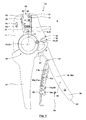
- a stripping tool 1 in the form of a manually operated wire stripper 2, without the invention being restricted to a hand-operated wire stripper 2.
- the stripper 2 has two jaws 3, 4. Between the two jaws 3, 4 a Abisolierizi 5 is added, which is formed with two stripping 6, 7.
- the stripping jaws 6, 7 are pivotable in an end region via a joint 8 in a direction parallel to the plane of the drawing Fig. 1 oriented pivot plane 9 pivotally connected to each other.
- the insulating jaws 6, 7 carry in their free end regions in each case a cutting element 10, 11.
- the jaws 3, 4 are pivotally connected to each other via a hinge 12 in the pivoting plane 9.
- a pivoting of the jaws 3, 4 toward each other is due to a contact via contact surfaces 13, 14 of the jaws 3, 4 with the stripping 6, 7 and / or the cutting elements 10, 11 associated with a pivoting of the stripping 6, 7.
- the pivot angle of Pliers jaws 3, 4 is smaller than the pivot angle of the stripping jaws 6, 7, since the distance of the contact surfaces 13, 14 of the joint 12 is greater than the distance of the contact surfaces 13, 14 of the joint 8.
- the Abisolierü 5 with the Stripping jaws 6, 7 without changing the pivot angle in the direction of a stripping 15 relatively displaceable, which is made possible by forming a sliding contact in the region of the contact surfaces 13, 14.
- a drive 16 generates both the cutting stroke and the Abisolierhub.
- the drive 16 is formed with two hand levers 17, 18 and a between the hand lever 17, 18 and the jaws 3, 4 and the Abisolierü 5 intermediate gear connection.
- the geared connection allows for a working stroke of the hand lever 17, 18 with pivoting of the hand lever 17, 18 successive to the cutting stroke and the Abisolierhub.
- the hand lever 18 forms a storage device 19, which the storage of other pairs of cutting elements 10 a, 11 a; 10b, 11b is used.
- the cutting elements 10a, 11a; 10b, 11b can be exchanged for the cutting elements mounted with the stripping jaws 6, 7 10, 11.
- the storage device 19 also stores jaws 20a, 20b; 21 a, 21 b, which can be exchanged against clamping jaws 20, 21, which are preferably formed elastically, in the outer end portion in grooves of the jaws 3, 4 are used and hold the inserted into the wire stripper 2 cables and fix. While the jaws 20, 21 in the state mounted with the jaws 3, 4 a relatively large extension vertically to the plane according to Fig.
- the jaws 20, 21 can be stored space-saving without the need to increase the extension of the hand lever 18 vertically to the plane when the jaws 20, 21 with their extension in the direction of the longitudinal axis of the cable (for in the jaws 3, 4 mounted Clamping jaws 20, 21) in the direction of the thickness of the hand lever 18 (ie vertically to the plane according to Fig. 1 ) are stored in the storage device 19.
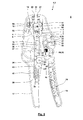
- the structure and the kinematics of the wire stripper 2 and the gear connection of the drive 16 are shown in the sectional view according to Fig.2
- the hand lever 17 and the jaw 3 are rigidly connected. With the forceps jaw 3 and the hand lever 17 thus a rigid rod member 22 is formed.
- the forceps jaw 4 is rotatably supported via the joint 12 in the pivoting plane 9 on the rigid rod part 22, which takes place by means of a bearing pin 23 held on the rigid rod part 22.
- the hand lever 18 is pivotally mounted via a hinge 24 in the pivot plane 9 on the rigid pliers part 22, which takes place here by a fixed to the rigid pliers part 22 bearing pin 25.
- a pressure lever 27 is articulated on the hand lever 18 via a joint 26, which takes place here by a bearing pin 28 fastened to the hand lever 18.
- a roller 30 is rotatably mounted on this via a bearing 29 in the pivoting plane 9.
- the roller 30 rolls on a guide contour 31, which has a (in particular approximately quarter circular) guide contour portion 32, a (in particular approximately coaxially to the stripping 15 oriented rectilinear) guide contour portion 33 and (in particular approximately parallel to the longitudinal axis of the pressure lever 27 oriented) guide contour portion 34th has.
- a hinge pin 35 with which the hinge 8 of the Abisolieraji 5 is formed, also serves the articulated connection of the Abisolieraji 5 with a pull tab 36.
- the pull tab 36 has only a translational degree of freedom along the Abisolierachse 15. This is ensured by a guide of the pull tab 36 on the one hand by a slot 37 of the pull tab 36, in which largely free of play transverse to the stripping 15 of the bearing pin 23, and passage of the joint 8 remote end portion of the pull tab 36 through a leading recess 38 a transverse to the stripping
- the stripping stroke with a movement of the pull tab 36 along the Abisolierachse 15 takes place under the action of a spring 40.
- the spring 40 is formed as a helical wound compression spring which wraps around the pull tab 36 with multiple gears and whose one Federfußddling is supported on the wall 39, while the other Federfußddling is supported on the pull tab 36, for example in the region of a paragraph 41 of the pull tab 36.
- the pull tab 36 is rotatably mounted in the pivot plane 9 via a bearing 42 a roller 43.
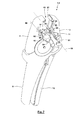
- Fig. 3 shows the wire stripper 2 in an insertion position. Without application of manual forces on the hand lever 17, 18 take both the hand lever 17, 18 and the jaws 3, 4 and the stripping 6, 7 from Fig. 3 apparent opening position. This is done by a prestressed in the open position spring 85, which acts on the stripping jaws 6, 7 and thus also the jaws 3, 4 and the hand lever 17, 18 in the opening direction. In this insertion, a cable 44 in one of the jaws 3, 4 and the stripping 6, 7 with attached cutting elements 10, 11 formed mouth 45 of the wire stripper 2 are inserted.
- the stripping jaw 7 and / or the cutting element 11 optionally carries a spacer 46 to which an end face of the cable 44 is brought into engagement with the insertion into the mouth 45, whereby a defined distance of knives 47, 48 of the cutting elements 10th , 11 from the front side of the cable 44 results.
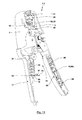
- a clamping and cutting stroke is performed by movement of the hand lever 17, 18 toward each other until the cutting position according to Fig. 4 is reached.
- the movement of the hand lever 18 in the direction of the hand lever 17 during the cutting and clamping stroke has the consequence that also the pressure lever is moved in the direction of the guide contour 31.
- the roller 30 While in the beginning region of the guide contour section 32 the roller 30 can still roll on the guide contour 31 without exerting significant forces on the forceps jaw 4, the inclination of the guide contour section 32 changes with increasing rolling movement of the roller 30 along the guide section, whereby an increasing force of the pressure lever 27 is applied to the jaw 4, so that increasingly a force acts on the jaw 4, which is directed to a pivoting of the jaw 4 in the direction of the jaw 3.
- the actuating force generated by the pressure lever 27 and the roller 30 on the guide contour portion 32 of the guide contour 31 act on the one hand on the clamping jaws 20, 21 caused clamping force for the lateral surface of the cable 44 and on the other hand, the cutting and pressing force of the knife 47, 48 of the Abisolierü 5 in an equilibrium of forces.
- the roller With the cutting position according to Fig. 4 the roller reaches the transition between the guide contour sections 32, 33. In this cutting position according to Fig. 4 is the role 30 of the pressure lever 27 on the roller 43 of the pull tab 36 at.
- the maximum stripping stroke is predetermined by the length of the guide contour section 33.
- Fig. 5 shows the stripped position. For this, the roller 30 has reached the transition region between the guide contour sections 33, 34.
- the Abisolierzange 2 with another tool namely a cutting device 50, equipped, which is also actuated by the operation of the hand lever 17, 18 and which has two knives 51, 52, by means of which with closure of the hand lever 17, 18 a in the cutting device 50 inserted cable can be completely severed (see, for the design of the cutting device and the geared connection with the hand levers and the above-mentioned prior art).
- the contact surface 14 for a stripping jaw 7 is formed directly by the jaw 3.
- the contact surface 13 for the other stripping jaw 6 is formed by a support element 53 which is displaceable by an adjusting element 54 such that, depending on the position of the support element 53, a change in the swivel angle of the stripping jaws 6, 7 with respect to the swivel angle of the jaws 3, 4 is possible.
- the blades 47, 48 penetrate into the cable 44 to accommodate different thicknesses of the insulation can.
- the adjustment member 54 extends through a guide slot 55 of the jaw 4, so that it can be moved from the outside by the user along the guide slot 55.
- the adjusting element 54 actuates the support element 53 via contact surfaces inclined in relation to the guide slot 55 in the manner of a double-wedge connection.
- Fig. 7 shows the wire stripper 2 in a three-dimensional view in the removal and change position.
- the ends of the stripping jaws 6, 7 facing away from the joint 8 are each equipped with mounting grooves 56, 57.
- the longitudinal axes of the mounting grooves 56, 57 each form mounting axles 58, 59.
- mounting elements 60, 61 of the cutting elements 10, 11 can be inserted into the mounting grooves 56, 57 of the stripping jaws 6, 7.
- the mounting grooves 56, 57 have extensions in the region of the bottom, with which undercuts are formed.
- the mounting elements 60, 61 are formed as projections with end extensions, which engage in the undercuts of the mounting grooves 56, 57, whereby a positive connection for receiving any forces in the pivot plane 9 is formed.
- a securing of the cutting elements 10, 11 relative to the stripping jaws 6, 7 takes place basically by the friction between the mounting grooves 56, 57 and the mounting members 60, 61.
- the mounting grooves 56, 57 and the mounting members 60, 61 each have a rough approximation T. -shaped cross-section.
- the positive engagement of the mounting member 60, 61 in the mounting groove 56, 57 may also be formed as a kind of dovetail joint 86.
- the cutting element 10, 11 is with its mounting member 60, 61 only in the change position according to Fig. 7 can be used in the mounting groove 56, 57, since in the change position, the mounting groove 56, 57 through a recess or a recess 62, 63 of a parallel to the pivot plane 9 oriented side wall 64, 65 of the jaw 3, 4 is accessible. Leaves the stripper 2 the change position according to Fig. 7 , the stripping jaws 6, 7 with the cutting elements 10, 11 held thereon are pushed forward relative to the side wall 64, 65, with which the cutting elements 10, 11 are no longer accessible.
- Fig. 8 shows in a spatial representation by way of example the cutting element 11 (wherein the other applies to the other cutting element 10).
- This is formed by way of example with a knife 48 with a straight trained cutting edge, where quite different cutting, for example, with at least one concave cutting edge or two successively arranged knife blades with straight edges, which are "V" -shaped, or even lamellar knife insert use can.
- the knife 48 is encapsulated with a holding body 67 made of plastic.
- the holding body 67 forms on the side facing away from the blade 48, a contact surface 68, with which the cutting element 11 can be supported on an associated contact surface 14 of the jaw 3. It can be seen further in Fig.
- handling areas 69 can be provided which simplify the manual handling of the cutting element 11.
- the mounting element 61 has a projection with a T-shaped enlargement in the end region.
- the handling surfaces 69 may be roughened to facilitate hand gripping.
- a guide groove 70 is present, which is open in the direction of the associated stripping 7.
- Fig. 9 shows a stripping jaw 7 with associated cutting element 11 in disassembled state.
- the mounting axis 58 is in this case oriented vertically to the plane of the drawing.
- the stripping jaw 7 also has a guide groove 71.
- the guide grooves 70, 71 complement one another to form a continuous rectilinear guide groove.
- This jointly formed guide serves to receive the spacer 46, which surrounds the stripping U-shaped on the side oriented to the mouth 45, wherein end-side angled portions of the vertical leg of the U in the guide grooves 70, 71 occur.
- the spacer 46 is displaceable along the guide grooves 70, 71 to change the length of the axial portion of the insulation to be removed.
- a detent or other fixation of a set position of the spacer may be provided, which is not shown here (see. DE 20 2008 014 111 U1 ). It is possible that the spacer 46 is mounted in disassembled state on the guide groove 70 of the cutting element 11 or the guide groove 71 of the stripping 7 and then the assembly of the cutting element 11 takes place with the stripping 7, which then the spacer 46 in the guide with the 70th , 71 formed common guide groove captive caught. It is understood that the stripping jaw 6 and the cutting element 10 are formed accordingly, u. U. but also with a mirrored design. The cutting elements 10, 11 for the two stripping jaws 6, 7 may also be formed identically, which can then be mounted in reverse orientation with the different stripping jaws 6, 7.
- At least one of the hand lever 17 may be formed with a sheath 72, which can be plugged, glued or otherwise connected to a base body of the hand lever 17. Over the sheath 72, a specification of elasticity can be made to bring about a soft gripping sensation. It is possible that by means of the sheath 72, for example by shape and / or color, an individualization of the wire stripper 2 for different customers. It is also possible that the sheathing 72 is adapted to different sizes of the user's hands of the stripping pliers 2.
- the hand lever 18 forming the storage device 19 which is in particular the movable hand lever, is formed with a base body 73 which serves to apply and transfer the actuating forces and thus has a corresponding rigidity.
- the base body 73 is formed in a rough approximation U-shaped in cross-section, wherein the opening of the U is oriented in the direction of the other hand lever 17.
- the U-shaped cross section of the main body 73 is here formed with a base leg 74 and two approximately parallel side legs 75, 76. Of the Grundköper 73 in the direction of the hand lever 17 open interior 79 is formed.
- the interior 79 of the base body 73 is limited on the one hand by a wall 77 and on the other hand by an end wall 78 of the hand lever 18.
- the interior 79 can be closed by means of a lid 80.
- the lid 80 is in the pliers head of the wire stripper 2 facing end region via a pivot bearing 81st hinged to the Grundköper 73 outside the interior 79.
- Fig. 1 and 2 show different pivoting positions of the lid 80, while Fig. 3 a closed position of the lid 80 shows.
- the main body 73 forms a latching nose 82 in the region of the wall 78 arranged in the free end region of the hand lever 18. In the closed position of the lid 80 according to Fig.
- mounting grooves 84 are provided, which are oriented vertically to the pivot plane 9 and to the plane of movement of the hand lever 17, 18 and the pivoting plane of the lid 80.
- mounting grooves 84 stocked for a replacement cutting elements 10, 11 are used. While the cutting elements 10, 11 for unfolded lid 80 can be pushed out of the mounting grooves 84 without further measures, an exit of the cutting elements 10, 11 for closed lid 80 is not possible because the exit of the cutting elements 10, 11 through which the side legs 75, 76 forming walls of the main body 73 is blocked.
- the mounting grooves 84 are formed corresponding to the mounting grooves 56, 57, so that the mounting members 60, 61 of the cutting elements 10, 11 can be used.
- the mounting grooves 84 provide a mounting axis 88, which transverse to the pivoting plane 9, in which the hand lever 17, 18 are pivoted, and perpendicular to the plane according to Fig. 1 are oriented.
- the cutting elements are also held on dovetail connections 87.
- the stripping jaws 6, 7 are equipped with the mounting grooves 56, 57, while the cutting elements 10, 11 are equipped with the mounting elements 60, 61. It is also possible that the stripping jaws 6, 7 have the mounting elements 60, 61, while the mounting grooves 56, 57 are provided on the cutting elements 10, 11.
- a "change position" in which only the assembly and disassembly of the cutting elements 10, 11 is possible, comprises both a discrete position and a position range. It is also possible that several change positions are available.
- Fig. 11 shows another embodiment of a wire stripper 2, which until further notice basically according to the wire stripper according to Fig. 1 to 10 can be trained.
- the wire stripper 2 is shown partially cut, with parts of the hand lever 17, 18 and the jaw 3 are cut away.
- the operating position of the wire stripper 2 can not be determined solely by the drive 16 formed with the hand levers 17, 18, the application of the actuating forces for the machining of the workpiece, in particular for cutting the insulation in the cutting stroke and stripping in the Abisolierhub, is responsible, to be changed.
- a manual change of an operating position and in particular the bringing about a change position is also possible manually via a further drive 89, which can be actuated without changing the hand lever 17, 18 and is not used for the machining of the workpiece.
- the further drive 89 is formed with a manual actuator 90.
- the actuator 90 is formed with the bearing pin 35, which is led out here via a slot, not shown, from a housing of the wire stripper 2 or freely accessible from the outside. It is possible that the actuating member 90 is guided along the Abisolierachse 15 with a slot in a rigid pliers part 22 associated housing. Will be in the in Fig.
- the actuator 90 in order to maintain a so-induced change position continue the actuator 90 must be applied manually, so that the spring 40 does not cause movement from the change position out. But it is also possible that in the thus induced change position, a latching or locking device 91 effectively which ensures the exchange position.
- the latching or locking device 91 can lock or lock any component which is moved to bring about the change position. If a latching device is used, it can generate a latching force which is greater than the force caused by the spring 40. The overcoming of the locking force is then carried out by the force of the spring 40 is supplemented by manually applied to the actuator 90 release forces, which are directed away from the change position. In the event that a locking device is used, a locked position can be left by manual removal of a locking element.
- Fig. 11 and 12 merely show an embodiment of a latching or locking device 91, without the invention being limited to this embodiment.
- the pull tab 36 in the end region, which passes through the recess 38 of the wall 39 of the hand lever 17, equipped with two axially spaced holes 92, 93.
- locking element 94 here a wire bow
- different axial positions of the pull tab 36 can be secured, wherein for the illustrated embodiment with the insertion of the locking element 94 into the bore 92 according to Fig. 12 a positive locking and thus locking the exchange position is possible.
- Fig. 12 it can be seen, is by actuation of the drive 89, a removal of the cutting elements 10, 11 in the insertion of the jaws 3, 4 and hand lever 17, 18 possible, so that alternatively a replacement in the insertion position and in the removal position is possible.
- one of at least one of the drives 16, 89 is subjected to motion-controlled release of the cutting elements 10, 11.
- a device device 19 in a hand lever 18 and a storage device 19 may be integrated into a pliers head 95.
- Storage devices 19a and 19b are integrated into the pliers head 95.
- the storage device 19a is integrated in the rigid pliers part 22, here in the pliers jaw 3.
- the storage device 19b is integrated into the movable pliers jaw 4.
- the jaws 3 and 4 each have a recess 96a, 96, which can be closed (at least partially) by a cover 80a, 80b.
- the covers 80a, 80b pivotally hinged to the jaws 3, 4 in the region of a hinge 97a, 97b, wherein the pivot axis of the hinge 97a, 97b vertically to the plane according to Fig. 13 and is oriented to the pivot plane 9 of the jaws 3, 4.
- accessories such as the cutting elements 10, 11, the jaws 20, 21 and / or knives 51, 52, releasably held, as previously described for the storage device 19, which is arranged in the region of the hand lever 18 has been.
- these accessories are held on the lid 80a, 80b via a dovetail connection 87a, 87b.
- the covers 80a, 80b may for this purpose have undercut mounting grooves 84, whose longitudinal axes predetermine a mounting axis 88, which are oriented vertically to the pivot plane 9 of the jaws 3, 4. It is understood that of the two storage devices 19a, 19b, only one storage device can be provided on a pliers head.
- the recess 96 a of the storage device 19 a between the front end portion of the jaw 3, on which the jaw 21 is held, and the hinge 24 is arranged. At least partially, the recess 96a extends laterally of the opposite to the jaw 3 slidably guided stripping jaw 7.
- the storage device 19b is arranged approximately in the region of the joint 12, namely laterally therefrom.
- the storage device 19, 19a, 19b are each formed in a pliers part 98, wherein this is preferably designed as a hand lever 18, as a pliers jaw 3, 4 or pliers head 95.
- the storage device 19 is used to store at least one arbitrary accessory 99 or different accessories, which may be, for example, a cutting element 9, 10, a jaw 20, 21, a knife 51, 52 and / or a press die for a pressing tongs ,
Landscapes
- Engineering & Computer Science (AREA)
- Mechanical Engineering (AREA)
- Gripping Jigs, Holding Jigs, And Positioning Jigs (AREA)
- Removal Of Insulation Or Armoring From Wires Or Cables (AREA)
- Scissors And Nippers (AREA)
- Clamps And Clips (AREA)
- Surgical Instruments (AREA)
- Knives (AREA)
Abstract
Die Erfindung betrifft ein Zangenteil (98), insbesondere einen Handhebel (18), mit einer Vorratseinrichtung (19) für die Bevorratung mindestens eines Zubehörteils (99). Erfindungsgemäß ist das Zangenteil (98) mit einem Grundkörper (73) und mit einem Deckel (80) gebildet. Der Grundkörper (73) besitzt einen offenen Querschnitt, welcher durch den Deckel (80) unter Ausbildung eines Innenraums (79) zumindest teilweise verschließbar ist. Das Zubehörteil (99) ist in dem Innenraum (79) angeordnet.The invention relates to a pliers part (98), in particular a hand lever (18), with a storage device (19) for the storage of at least one accessory (99). According to the invention, the pliers part (98) is formed with a base body (73) and with a cover (80). The base body (73) has an open cross section, which is at least partially closed by the lid (80) forming an interior space (79). The accessory (99) is disposed in the interior space (79).
Description
Die Erfindung betrifft ein Zangenteil für eine Zange, insbesondere eine Abisolierzange. Das Zangenteil ist mit einer Vorratseinrichtung ausgestattet, in welcher ein Zubehörteil, insbesondere ein Schneidelement, Klemmelement und/oder Presselement der Zange bevorratet werden kann. Des Weiteren betrifft die Erfindung eine Zange oder eine Abisolierzange, welche mit einem derartigen Zangenteil ausgestattet ist.The invention relates to a pliers part for pliers, in particular a wire stripper. The pliers part is equipped with a storage device in which an accessory, in particular a cutting element, clamping element and / or pressing element of the pliers can be stored. Furthermore, the invention relates to a pair of pliers or a wire stripper, which is equipped with such a pliers part.
Zangen können über Zubehörteile, insbesondere Austauschteile verfügen. Beispielsweise kann es sich bei einem derartigen Zubehörteil um austauschbare Schneidelemente wie Schneidmesser, Klemmelemente wie Klemmbacken und/oder Presselemente wie Pressgesenke handeln. Hierbei kann ein Austausch eines derartigen Zubehörteils verschleißbedingt erforderlich sein und/oder erfolgen, um Werkstücke unterschiedlicher Geometrien und Typen mit der Zange bearbeiten zu können. Beispielsweise können unterschiedliche Pressgesenke, Klemmbacken oder Schneidmesser Einsatz finden, die unterschiedlich konturierte Schneiden, Gesenkflächen oder Klemmflächen besitzen. Problematisch ist hierbei die Bevorratung der Zubehörteile. Im einfachsten Fall führt der Benutzer die Zubehörteile lose mit sich oder bevorratet diese in einer Werkzeugkiste.Pliers may have accessories, especially replacement parts. For example, such an accessory can be exchangeable cutting elements such as cutting knives, clamping elements such as clamping jaws and / or pressing elements such as press dies. In this case, replacement of such an accessory may be required due to wear and / or to be able to process workpieces of different geometries and types with the pliers. For example, different pressing dies, clamping jaws or cutting blades can be used which have differently contoured cutting edges, die surfaces or clamping surfaces. The problem here is the storage of accessories. In the simplest case, the user loosely carries the accessories with them or stores them in a toolbox.
Die Druckschrift
Die Druckschrift
Der vorliegenden Erfindung liegt die Aufgabe zugrunde, ein Zangenteil, eine Zange und eine Abisolierzange vorzuschlagen, welches oder welche eine alternative oder verbesserte Bevorratung zumindest eines Zubehörteils ermöglicht.The present invention has for its object to provide a pliers, a pair of pliers and a wire stripper, which or which allows an alternative or improved storage of at least one accessory.
Die Aufgabe der Erfindung wird erfindungsgemäß mit den Merkmalen der unabhängigen Patentansprüche gelöst. Weitere bevorzugte erfindungsgemäße Ausgestaltungen sind den abhängigen Patentansprüchen zu entnehmen.The object of the invention is achieved with the features of the independent claims. Further preferred embodiments according to the invention can be found in the dependent claims.
Die Erfindung schlägt ein Zangenteil vor, welches für eine beliebige Zange einsetzbar ist. Hierbei wird unter einer Zange jedwedes Werkzeug verstanden, bei welchem über zwei Handhebel unter Verschwenkung der Handhebel relativ zueinander manuell Betätigungskräfte erzeugt werden, mittels welchen (ggf. mit einer Über- oder Untersetzung durch eine getriebliche Verbindung) mittels der Zange eine Bearbeitung eines Werkstücks erfolgt. Insbesondere sind die Zangenteile bestimmt für eine Abisolierzange.The invention proposes a pliers part, which can be used for any pliers. In this case, any tool is understood by a pair of pliers, in which two manual levers are generated by pivoting the hand lever relative to each other manually actuating forces, by means of which (possibly with a transmission or reduction by a geared connection) by means of a pair of pliers, a machining of a workpiece. In particular, the pliers parts are intended for a wire stripper.
Erfindungsgemäß ist das Zangenteil zumindest zweistückig ausgebildet, nämlich mit einem Grundkörper sowie einem Deckel. Der Grundkörper kann ein- oder mehrteilig ausgebildet sein und besitzt einen offenen Querschnitt, der durch den ein- oder mehrteilig ausgebildeten Deckel zumindest teilweise verschließbar ist. Der Deckel und der offene Querschnitt des Grundkörpers begrenzen gemeinsam einen Innenraum des Zangenteils. In diesem Innenraum kann (mindestens) ein Zubehörteil angeordnet werden. Möglich ist hierbei, dass das Zubehörteil lose in dem Innenraum angeordnet ist oder dass das Zubehörteil in dem Innenraum fixiert ist. Durch den Deckel kann eine Verliersicherung des Zubehörteils aus dem Innenraum des Zangenteils gebildet sein. Ebenfalls möglich ist, dass durch den Deckel eine (zumindest teilweise) Abdichtung des Innenraums erfolgt, womit der Innenraum und die darin angeordneten Zubehörteile gegenüber Verunreinigungen und/oder Beschädigungen geschützt sind. Möglich ist auch, dass durch den Deckel ein optisch ansprechender Verschluss des Innenraums und eine Gestaltung der Mantelfläche des Zangenteils bereitgestellt ist. Durch die äußere Formgebung des Deckels und des Grundkörpers kann trotz der Bevorratung der Zubehörteile in dem Innenraum des Zangenteils auch eine für die Hand des Benutzers angenehme Außenkontur bereitgestellt werden, was insbesondere dann von Interesse ist, wenn es sich bei dem Zangenteil um einen Handhebel handelt.According to the invention the pliers part is formed at least two pieces, namely with a base body and a lid. The main body may be formed in one or more parts and has an open cross section, which is at least partially closed by the one or more parts lid. The lid and the open cross-section of the base body together define an interior of the pliers part. In this interior (at least) an accessory can be arranged. It is possible here that the accessory is arranged loosely in the interior or that the accessory is fixed in the interior. Through the lid, a captive securing the accessory can be formed from the interior of the pliers part. It is also possible that the lid (at least partially) sealing of the interior takes place, whereby the interior and the accessories arranged therein are protected against contamination and / or damage. It is also possible that a visually appealing closure of the interior and a design of the lateral surface of the pliers part is provided by the lid. Through the outer In spite of the provision of the accessories in the interior of the pliers part, shaping of the cover and of the basic body can also provide an outer contour that is pleasant for the user's hand, which is of particular interest when the pliers part is a hand lever.
Sofern das Zubehörteil nicht lose in dem Innenraum bevorratet werden soll, kann dieses beispielsweise an dem Grundkörper des Zangenteils gehalten werden. Dies kann bspw. durch Verrastung in dem Grundkörper, Verschraubung mit diesem oder Einführen in eine von dem Grundkörper ausgebildete Montagenut erfolgen. In bevorzugter Ausgestaltung der Erfindung wird das Zubehörteil aber an dem Deckel gehalten. Dies hat den Vorteil, dass mit Aufklappen des Deckels oder Demontage des Deckels das Zubehörteil besonders einfach zugänglich ist. Durchaus möglich ist sogar, dass einer Zange mehrere Deckel zugeordnet sind, welche austauschbar sind und an welchen jeweils unterschiedliche Zubehörteile gehalten sind. Somit kann der Benutzer die Zange mit einem Deckel mit Zubehörteilen, welche für den bevorstehenden Einsatz geeignet sind, ausstatten, während andere Zubehörteile, welche derzeit nicht von Interesse sind, an einem anderen Deckel bevorratet werden können, welcher dann beispielsweise in einer Werkzeugkiste abgelegt werden kann.If the accessory is not to be stored loosely in the interior, this can for example be held on the main body of the pliers part. This can be done, for example, by latching in the base body, screwing with this or insertion into a mounting groove formed by the base body. In a preferred embodiment of the invention, however, the accessory is held on the lid. This has the advantage that the accessory is particularly easy to access by unfolding the lid or disassembly of the lid. It is quite possible even that a pair of pliers are associated with a plurality of lids, which are interchangeable and on each of which different accessories are held. Thus, the user can provide the pliers with a lid with accessories suitable for the upcoming use, while other accessories that are currently not of interest can be stored on another lid, which can then be stored, for example, in a tool box ,
Für die Befestigung und Lagerung des Deckels an dem Grundkörper des Zangenteils gibt es vielfältige Möglichkeiten. Um lediglich einige nicht beschränkende Beispiele zu nennen, kann der Deckel mit dem Grundkörper verschraubt, vernietet, verclipst, in den Grundkörper eingeschoben o. ä. werden. Für eine erfindungsgemäße Ausgestaltung ist der Deckel verschwenkbar an dem Grundkörper des Zangenteils gelagert. In diesem Fall kann der Deckel eine Schließstellung besitzen, in welcher der Deckel den Grundkörper des Zangenteils zumindest teilweise verschleißt, sowie eine Öffnungsstellung, in welcher der Deckel von dem Grundkörper des Zangenteils weggeschwenkt ist und welche die Entnahme und das Einführen von Zubehörteilen in den Deckel oder den Grundkörper des Zangenteils ermöglichen kann.For the attachment and storage of the lid on the body of the pliers part there are many possibilities. To name but a few non-limiting examples, the lid may be bolted, riveted, clipped, inserted into the body, or the like, with the body. For an inventive embodiment, the lid is pivotally mounted on the main body of the pliers part. In this case, the lid may have a closed position, in which the cover at least partially wears the main body of the pliers part, and an open position, in which the lid is pivoted away from the main body of the pliers part and which the removal and insertion of accessories in the lid or can allow the main body of the pliers part.
In bevorzugter Weiterbildung des Zangenteils ist der Deckel in einer Schließstellung mit dem Grundkörper verrastet oder verriegelt.In a preferred embodiment of the pliers part of the lid is locked or locked in a closed position with the main body.
Durchaus möglich ist, dass das Zubehörteil gesonderte Halteorgane, insbesondere einen Vorsprung, eine Vertiefung, ein Stift, ein Rast- oder Verriegelungselement, besitzt, über welches dieses in dem Innenraum des Zangenteils gehalten werden kann. In bevorzugter Ausgestaltung ist aber das Zubehörteil, welches als austauschbares Schneidelement, Klemmelement oder Presselement ausgebildet sein kann, zur Bevorratung in dem Zangenteil über denselben Haltemechanismus in dem Innenraum gehalten wie in einer Betriebsstellung in einem Zangenkopf. Damit erübrigt sich die Ausstattung des Zubehörteils mit unterschiedlichen Haltemechanismen einerseits für die Befestigung desselben in der Betriebsstellung an einem Zangenkopf und andererseits das Halten für die Bevorratung in dem Zangenteil.It is entirely possible that the accessory has separate holding members, in particular a projection, a recess, a pin, a latching or locking element, via which it can be held in the interior of the pliers part. In a preferred embodiment but is the accessory, which may be formed as an exchangeable cutting element, clamping element or pressing element, held for storage in the pliers part on the same holding mechanism in the interior as in an operating position in a pliers head. This eliminates the equipment of the accessory with different holding mechanisms on the one hand for the attachment of the same in the operating position on a pliers head and on the other hand, the holding for the storage in the pliers part.
Für den Haltemechanismus zwischen Zubehörteil und Grundkörper oder Deckel gibt es vielfältige Möglichkeiten. Für einen Vorschlag der Erfindung ist das Zubehörteil über eine Schwalbenschwanz-Verbindung an dem Zangenteil gehalten. Hierbei bildet der Grundkörper oder der Deckel eine Montagenut oder ein Montageelement der Schwalbenschwanz-Verbindung aus. Die Montage der Schwalbenschwanz-Verbindung zwischen Zubehörteil und Deckel oder Grundkörper erfolgt in Richtung einer Montageachse, welche vertikal zu einer Schwenkebene der Handhebel und/oder Zangenbacken der Zange orientiert ist. Hierbei umfasst eine "Schwalbenschwanz-Verbindung" auch Konturen des Montagelements einerseits und der Montagenut andererseits, welche nicht der strengen Form eines "Schwalbenschwanzes" entsprechen, solange noch ein formschlüssiger Eingriff unter Ausbildung mindestens einer geeigneten Hinterschneidung gewährleistet ist. Die erfindungsgemäße formschlüssige Verbindung über eine Art Schwalbenschwanz-Verbindung mit dem formschlüssigen Eingriff eines Montagelements in eine Montagenut ermöglicht einerseits ein einfaches Einführen entlang der durch die Montagenut vorgegebenen Montageachse. Andererseits ermöglicht der formschlüssige Eingriff eine exakte Vorgabe der Ausrichtung des Zubehörteils relativ zu dem Deckel oder dem Grundkörper des Zangenteils. Für den Fall, dass dieselbe Schwalbenschwanz-Verbindung verwendet wird, um das Zubehörteil in der Betriebsstellung am Zangenkopf zu halten, ermöglicht die Schwalbenschwanz-Verbindung eine gute Aufnahme und Übertragung von Kräften zwischen Zangenkopf und Zubehörteil.There are many possibilities for the holding mechanism between the accessory and the base or lid. For a proposal of the invention, the accessory is held on the pliers part via a dovetail connection. Here, the main body or the lid forms a mounting groove or a mounting member of the dovetail joint. The assembly of the dovetail connection between the accessory and cover or base body takes place in the direction of a mounting axis, which is oriented vertically to a pivot plane of the hand lever and / or jaws of the pliers. Here, a "dovetail connection" also contours of the mounting element on the one hand and the mounting groove on the other hand, which do not conform to the strict form of a "dovetail", as long as a positive engagement to form at least one suitable undercut is guaranteed. The positive connection according to the invention via a type of dovetail connection with the positive engagement of a mounting element in a mounting groove on the one hand enables easy insertion along the assembly axis predetermined by the mounting groove. On the other hand, the positive engagement allows an exact specification of the orientation of the accessory relative to the cover or the body of the pliers part. In the event that the same dovetail connection is used to hold the accessory in the operating position on the pliers head, the dovetail connection allows a good absorption and transmission of forces between the pliers head and accessory.
Für die Sicherung des Zubehörteils gegenüber dem Deckel oder Grundkörper bei Einsatz einer Schwalbenschwanz-Verbindung gibt es vielfältige Möglichkeiten. Unter Umständen kann die Reibung zwischen der Montagenut und dem Montageelement für diese Sicherung ausreichend sein. Möglich ist, dass auch eine Rast- oder Verriegelungseinrichtung zur Sicherung Einsatz findet. Für einen besonderen Vorschlag der Erfindung ist das Zubehörteil an dem Deckel des Zangenteils gehalten. Hierbei bildet das Zubehörteil das Montagelement der Schwalbenschwanz-Verbindung aus, während der Deckel die Montagenut der Schwalbenschwanz-Verbindung ausbildet. In geschlossenem Zustand des Deckels ist ein Austritt des Montageelements des Zubehörteils aus der Montagenut des Deckels blockiert durch eine den Innenraum begrenzende Innenwandung des Grundkörpers. Dies stellt eine besonders einfache, aber dennoch zuverlässige Sicherung der Position des Zubehörteils in der Montagenut des Deckels dar.There are many possibilities for securing the accessory to the cover or body when using a dovetail connection. Under certain circumstances, the friction between the mounting groove and the mounting element for this backup may be sufficient. It is possible that a locking or locking device is used for backup. For a particular proposal of the invention, the accessory is held on the lid of the pliers part. In this case, the accessory forms the mounting element of the dovetail connection, while the lid forms the mounting groove of the dovetail connection formed. In the closed state of the lid, an outlet of the mounting element of the accessory from the mounting groove of the cover is blocked by an inner wall bounding the inner wall of the base body. This represents a particularly simple, yet reliable assurance of the position of the accessory in the mounting groove of the lid.
Für eine erfindungsgemäße Ausführungsform handelt es sich bei dem Zangenteil, welches die Vorratseinrichtung besitzt, um einen Zangenkopf. Möglich ist hierbei auch, dass das Zangenteil, in welches die Vorratseinrichtung integriert ist, eine Zangenbacke ist.For an embodiment according to the invention, the pliers part which has the storage device is a pliers head. It is also possible here that the pliers part, in which the storage device is integrated, is a pliers jaw.
In bevorzugter Ausgestaltung ist das Zangenteil als Handhebel ausgebildet.In a preferred embodiment, the pliers part is designed as a hand lever.
Für die Anordnung des Deckels an dem Handhebel gibt es ebenfalls vielfältige Möglichkeiten. Durchaus denkbar, dass der Deckel eine einem Kopf der Zange abgewandte Stirnseite des Handhebels verschließt. Eine vergrößerte Fläche kann der Deckel besitzen (und damit u. U. die Bevorratung einer größeren Zahl von Zubehörteilen ermöglichen), wenn der Deckel im Bereich einer Längsfläche des Handhebels angeordnet ist. Ist beispielsweise der Deckel auf einer Seite des Handhebels angeordnet, welche in montiertem Zustand dem anderen Handhebel abgewandt ist, kann der Deckel frei von dem Handhebel entnommen oder nach außen abgeklappt werden, ohne dass diese Bewegung durch den anderen Handhebel beschränkt oder blockiert ist. Das Entsprechende gilt dann, wenn der Deckel auf einer Seite des Handhebels montiert ist, deren Flächennormale vertikal zu der Schwenkebene der Handhebel orientiert ist. In bevorzugter Ausgestaltung der Erfindung ist aber der Deckel auf der Seite des Grundkörpers angeordnet, welche in einem montierten Zustand des Handhebels dem anderen Handhebel zugewandt ist. Dieser Ausgestaltung liegt insbesondere die Erkenntnis zugrunde, dass bei der Applikation von Handkräften auf die beiden Handhebel keine Beaufschlagung dieser Seite durch die Hand des Benutzers erfolgt. Damit ist der Deckel nicht den Handkräften ausgesetzt. Andererseits sind die Anforderungen an die Konturgebung des Deckels für die Ermöglichung einer guten Haptik des Abisolierwerkzeugs für eine derartige Anordnung des Deckels zumindest verringert. Dieser Ausgestaltung der Erfindung nutzt u.U. auch die Erkenntnis, dass für die auseinandergespreizten Handhebel zwischen den Handhebeln ein ausreichender Zwischenraum verbleibt, um den Deckel zu montieren und demontieren oder auf- und zuzuschwenken. Eine Montage des Zubehörteils mit dem Handhebel kann in Richtung einer beliebigen Montageachse erfolgen, beispielsweise in Richtung der Längsachse des Handhebels mit Einschieben des Zubehörteils in eine Montagenut. In bevorzugter Ausgestaltung ist aber das Zubehörteil in Richtung einer Montageachse montierbar oder demontierbar, die quer zur Längsachse des Handhebels orientiert ist. Eine Montage in Richtung einer derartigen Montageachse ist besonders einfach, insbesondere da die Montage nicht durch den anderen Handhebel behindert ist. Ein Nachteil der Ausgestaltung gemäß der Druckschrift
In bevorzugter Ausgestaltung ist hierbei der Deckel in seinem dem Zangenkopf zugewandten Endbereich verschwenkbar an dem Grundkörper gelagert. Diese Ausgestaltung macht sich zu Nutze, dass die beiden an einer Zange montierten Handhebel eine Öffnungsstellung besitzen, bei welcher diese einen ungefähr kreissegmentförmigen Zwischenraum freigeben. Mit Anlenkung des Deckels in dem dem Zangenkopf zugewandten Endbereich an dem Grundkörper kann auch der Deckel gegenüber dem Grundkörper eine Öffnungsstellung einnehmen, in welcher Deckel und Grundkörper kreissegmentartig angeordnet sind. Hierbei liegen die beiden einerseits von den Handhebeln sowie andererseits von dem Deckel und dem Grundkörper gebildeten Kreissegmente so ineinander, dass für vorgegebenen Öffnungswinkel der Handhebel eine maximale Öffnung des Deckels gegenüber dem Grundkörper ermöglicht ist.In a preferred embodiment, in this case, the lid is pivotally mounted on the base body in its end region facing the pliers head. This embodiment takes advantage of the fact that the two mounted on a pair of pliers hand lever have an open position in which they release an approximately circular segment-shaped gap. With articulation of the lid in the end region facing the pliers head on the main body and the lid relative to the main body can assume an open position, in which lid and body are arranged like a circle. In this case, the two are on the one hand of the hand levers and on the other hand formed by the lid and the base circle segments such that for a given opening angle of the lever a maximum opening of the lid relative to the body is possible.
Erfindungsgemäß kann das Zangenteil der zuvor erläuterten Art Einsatz finden in einer Zange.According to the invention, the pliers part of the type described above can be used in pliers.
Die Erfindung schlägt des Weiteren eine Abisolierzange vor, bei welchem ein Zangenteil der zuvor erläuterten Art Einsatz findet. Das Abisolierwerkzeug verfügt über eine Abisoliereinheit.The invention further proposes a wire stripper, in which a pliers part of the type described above is used. The stripping tool has an Abisoliereinheit.
Eine Betriebsstellung der Abisoliereinheit ist mit einem Schneidhub in einer Schwenkebene durch einen mit dem oder dem Handhebel gebildeten Antrieb veränderbar. Die Abisoliereinheit ist des Weiteren über den Antrieb über einen Abisolierhub entlang einer Abisolierachse bewegbar. Ein das Zubehörteil bildendes Schneidelement ist auswechselbar mit der Abisolier-einheit montiert. Hierbei erfolgt die Montage des Schneidelements mit der Abisoliereinheit über eine Montagenut, in welche formschlüssig ein Montageelement einschiebbar ist. Vorzugsweise besitzt die Abisoliereinheit die Montagenut, während das Montageelement an dem Schneid-element vorgesehen ist. Einsatz findet somit eine mit dem Montagelement und der Montagenut gebildete Schwalbenschwanz-Verbindung zwischen Schneidelement und Abisoliereinheit. Der Grundkörper oder der Deckel des Zangenteils besitzt ein Montageelement oder eine Montagenut, welches oder welche korrespondierend zu dem Montagelement oder der Montagenut der Abisoliereinheit ausgebildet ist. Das Schneidelement ist unter Nutzung seines Montageelements oder seiner Montagenut auch unter Ausbildung einer Schwalbenschwanz-Verbindung an dem Montageelement oder der Montagenut des Deckels oder des Grundkörpers in dem Innenraum des Zangenteils gehalten.An operating position of the Abisoliereinheit is changeable with a cutting stroke in a pivoting plane by a drive formed with the hand lever or. The Abisoliereinheit is further movable via the drive via a Abisolierhub along a Stripping. A cutting element forming the accessory is interchangeable with the stripping unit. In this case, the assembly of the cutting element with the Abisoliereinheit via a mounting groove into which a form-fitting mounting element is inserted. Preferably, the Abisoliereinheit has the mounting groove, while the mounting member is provided on the cutting element. Use is thus a formed with the mounting member and the mounting groove dovetail connection between the cutting element and Abisoliereinheit. The main body or the lid of the pliers part has a mounting member or a mounting groove which is formed corresponding to the mounting member or the mounting groove of the Abisoliereinheit. The cutting element is held using its mounting member or its mounting groove to form a dovetail connection to the mounting member or the mounting groove of the lid or the body in the interior of the pliers part.
Vorteilhafte Weiterbildungen der Erfindung ergeben sich aus den Patentansprüchen, der Beschreibung und den Zeichnungen. Die in der Beschreibung genannten Vorteile von Merkmalen und von Kombinationen mehrerer Merkmale sind lediglich beispielhaft und können alternativ oder kumulativ zur Wirkung kommen, ohne dass die Vorteile zwingend von erfindungsgemäßen Ausführungsformen erzielt werden müssen. Ohne dass hierdurch der Gegenstand der beigefügten Patentansprüche verändert wird, gilt hinsichtlich des Offenbarungsgehalts der ursprünglichen Anmeldungsunterlagen und des Patents Folgendes: weitere Merkmale sind den Zeichnungen - insbesondere den dargestellten Geometrien und den relativen Abmessungen mehrerer Bauteile zueinander sowie deren relativer Anordnung und Wirkverbindung - zu entnehmen. Die Kombination von Merkmalen unterschiedlicher Ausführungsformen der Erfindung oder von Merkmalen unterschiedlicher Patentansprüche ist ebenfalls abweichend von den gewählten Rückbeziehungen der Patentansprüche möglich und wird hiermit angeregt. Dies betrifft auch solche Merkmale, die in separaten Zeichnungen dargestellt sind oder bei deren Beschreibung genannt werden. Diese Merkmale können auch mit Merkmalen unterschiedlicher Patentansprüche kombiniert werden. Ebenso können in den Patentansprüchen aufgeführte Merkmale für weitere Ausführungsformen der Erfindung entfallen.Advantageous developments of the invention will become apparent from the claims, the description and the drawings. The advantages of features and of combinations of several features mentioned in the description are merely exemplary and can take effect alternatively or cumulatively, without the advantages having to be achieved by embodiments according to the invention. Without thereby altering the subject matter of the appended claims, as regards the disclosure of the original application documents and the patent, further features can be found in the drawings, in particular the illustrated geometries and the relative dimensions of several components and their relative arrangement and operative connection. The combination of features of different embodiments of the invention or of features of different claims is also possible deviating from the chosen relationships of the claims and is hereby stimulated. This also applies to those features which are shown in separate drawings or are mentioned in their description. These features can also be combined with features of different claims. Likewise, in the claims listed features for further embodiments of the invention can be omitted.
Die in den Patentansprüchen und der Beschreibung genannten Merkmale sind bezüglich ihrer Anzahl so zu verstehen, dass genau diese Anzahl oder eine größere Anzahl als die genannte Anzahl vorhanden ist, ohne dass es einer expliziten Verwendung des Adverbs "mindestens" bedarf. Wenn also beispielsweise von einem Element wie einem Schneidelement, einer Abisolierbacke oder einer Montagenut die Rede ist, ist dies so zu verstehen, dass genau ein Element, zwei Elemente oder mehr Elemente vorhanden sein können. Diese Merkmale können durch andere Merkmale ergänzt werden oder die einzigen Merkmale sein, aus denen das jeweilige Erzeugnis besteht.The features mentioned in the patent claims and the description are to be understood in terms of their number that exactly this number or a greater number than the said number is present, without requiring an explicit use of the adverb "at least". If, for example, an element such as a cutting element, a stripping jaw or a mounting groove is mentioned, it is to be understood that exactly one element, two elements or more elements may be present. These features may be supplemented by other features or be the only characteristics that make up the product in question.
Die in den Patentansprüchen enthaltenen Bezugszeichen stellen keine Beschränkung des Umfangs der durch die Patentansprüche geschützten Gegenstände dar. Sie dienen lediglich dem Zweck, die Patentansprüche leichter verständlich zu machen.The reference numerals contained in the claims do not limit the scope of the objects protected by the claims. They are for the sole purpose of making the claims easier to understand.
Im Folgenden wird die Erfindung anhand in den Figuren dargestellter bevorzugter Ausführungs-beispiele weiter erläutert und beschrieben.
- Fig. 1
- zeigt eine Abisolierzange in einer Einführstellung mit geöffneter Vorratseinrichtung in einer Draufsicht.
- Fig. 2
- zeigt die Abisolierzange gemäß
Fig. 1 in der Einführstellung mit geöffneter Vorratseinrichtung bei Schnittführung parallel zur Zeichenebene gemäßFigur 1 . - Fig. 3
- zeigt die Abisolierzange gemäß
Fig. 1 und2 in der Einführstellung mit eingeführtem Kabel und geschlossener Vorratseinrichtung bei Schnittführung parallel zur Zeichenebene gemäßFigur 1 . - Fig. 4
- zeigt die Abisolierzange gemäß
Fig. 1 bei Schnittführung parallel zur Zeichenebene gemäßbis 3Figur 1 in einer Schneid- und Klemmstellung, wobei die Handhebel gegenüberFig. 3 über einen Schneidhub teilweise geschlossen sind. - Fig. 5
- zeigt die Abisolierzange gemäß
Fig. 1 bei Schnittführung parallel zur Zeichenebene gemäßbis 4Figur 1 in einer Abisolierstellung, wobei die Handhebel gegenüberFig. 4 über einen Abisolierhub weiter geschlossen sind. - Fig. 6
- zeigt die Abisolierzange gemäß
Fig. 1 bei Schnittführung parallel zur Zeichenebene gemäßbis 5Figur 1 in einer Wechsel- und Entnahmestellung, wobei die Handhebel gegenüberFig. 5 weiter geschlossen sind. - Fig. 7
- zeigt die Abisolierzange gemäß den
Fig. 1 in einer räumlichen Darstellung bei demontierten Schneidelement.bis 6 - Fig. 8
- zeigt ein Schneidelement in einer räumlichen Darstellung.
- Fig. 9
- zeigt in einer Explosionsdarstellung ein Schneidelement und die zugeordnete Abisolierbacke.
- Fig. 10
- zeigt eine Draufsicht auf eine Abisolierzange mit einem Handhebel, der mit einer separaten Ummantelung gebildet ist.
- Fig. 11
- zeigt in einer teilgeschnittenen räumlichen Darstellung eine weitere Ausführungsform einer Abisolierzange.
- Fig. 12
- zeigt in einer veränderten teilgeschnittenen räumlichen Ansicht die Abisolierzange gemäß
Fig. 11 . - Fig. 13
- zeigt einen Zangenkopf einer weiteren Abisolierzange mit in den Zangenkopf integrierten Vorratseinrichtungen für Zubehörteile, wobei hier die Vorratseinrichtungen in einer geöffneten Stellung dargestellt sind.
- Fig. 14
- zeigt den Zangenkopf gemäß
Fig. 13 , wobei hier die Vorratseinrichtungen in einer geschlossenen Stellung dargestellt sind.
- Fig. 1
- shows a wire stripper in an insertion position with open storage device in a plan view.
- Fig. 2
- shows the wire stripper according to
Fig. 1 in the insertion with open storage device when cutting parallel to the plane according toFIG. 1 , - Fig. 3
- shows the wire stripper according to
Fig. 1 and2 in the insertion with inserted cable and closed storage device when cutting parallel to the plane according toFIG. 1 , - Fig. 4
- shows the wire stripper according to
Fig. 1 to 3 when cutting parallel to the plane according toFIG. 1 in a cutting and clamping position, with the hand lever oppositeFig. 3 Partially closed over a cutting stroke. - Fig. 5
- shows the wire stripper according to
Fig. 1 to 4 when cutting parallel to the plane according toFIG. 1 in a stripping position, with the hand lever oppositeFig. 4 are closed further via a stripping stroke. - Fig. 6
- shows the wire stripper according to
Fig. 1 to 5 when cutting parallel to the plane according toFIG. 1 in an exchange and removal position, with the hand lever oppositeFig. 5 are closed further. - Fig. 7
- shows the wire stripper according to the
Fig. 1 to 6 in a spatial representation with disassembled cutting element. - Fig. 8
- shows a cutting element in a spatial representation.
- Fig. 9
- shows in an exploded view a cutting element and the associated stripping jaw.
- Fig. 10
- shows a plan view of a wire stripper with a hand lever, which is formed with a separate sheath.
- Fig. 11
- shows in a partially sectioned spatial representation of another embodiment of a wire stripper.
- Fig. 12
- shows in a modified partially cutaway spatial view of the wire stripper according to
Fig. 11 , - Fig. 13
- shows a pliers head of another wire stripper with integrated into the pliers head storage devices for accessories, in which case the storage devices are shown in an open position.
- Fig. 14
- shows the pliers head according to
Fig. 13 , wherein here the storage devices are shown in a closed position.
In den Fig. ist ein Abisolierwerkzeug 1 in Form einer handbetätigten Abisolierzange 2 dargestellt, ohne dass die Erfindung auf eine handbetätigte Abisolierzange 2 beschränkt sein soll. Die Abisolierzange 2 verfügt über zwei Zangenbacken 3, 4. Zwischen den beiden Zangenbacken 3, 4 ist eine Abisoliereinheit 5 aufgenommen, welche mit zwei Abisolierbacken 6, 7 gebildet ist. Die Abisolierbacken 6, 7 sind in einem Endbereich über ein Gelenk 8 verschwenkbar in einer parallel zur Zeichenebene gemäß
Ein Antrieb 16 erzeugt sowohl den Schneidhub als auch den Abisolierhub. Für das dargestellte Ausführungsbeispiel ist der Antrieb 16 mit zwei Handhebeln 17, 18 sowie einer zwischen die Handhebel 17, 18 und die Zangenbacken 3, 4 und die Abisoliereinheit 5 zwischengeordneten getrieblichen Verbindung gebildet. Die getriebliche Verbindung ermöglicht für einen Arbeitshub der Handhebel 17, 18 mit Verschwenkung der Handhebel 17, 18 aufeinander zu nacheinander den Schneidhub und den Abisolierhub.A
Der Handhebel 18 bildet eine Vorratseinrichtung 19 aus, welche der Bevorratung von weiteren Paaren von Schneidelementen 10a, 11a; 10b, 11 b dient. Die Schneidelemente 10a, 11a; 10b, 11 b können ausgetauscht werden gegen die mit den Abisolierbacken 6, 7 montierten Schneidelemente 10, 11. Für das dargestellte Ausführungsbeispiel bevorratet die Vorratseinrichtung 19 auch Klemmbacken 20a, 20b; 21 a, 21 b, welche gegen Klemmbacken 20, 21 ausgetauscht werden können, die vorzugsweise elastisch ausgebildet sind, im außenliegenden Endbereich in Nuten der Zangenbacken 3, 4 einsetzbar sind und das in die Abisolierzange 2 eingelegte Kabel halten und fixieren. Während die Klemmbacken 20, 21 in dem mit den Zangenbacken 3, 4 montierten Zustand eine verhältnismäßig große Erstreckung vertikal zur Zeichenebene gemäß
Der Aufbau und die Kinematik der Abisolierzange 2 und der getrieblichen Verbindung des Antriebs 16 sind in der geschnittenen Darstellung gemäß
Ein Lagerbolzen 35, mit welchem das Gelenk 8 der Abisoliereinheit 5 gebildet ist, dient auch der gelenkigen Verbindung der Abisoliereinheit 5 mit einer Zuglasche 36. Die Zuglasche 36 verfügt lediglich über einen translatorischen Freiheitsgrad entlang der Abisolierachse 15. Dieser wird gewährleistet durch eine Führung der Zuglasche 36 einerseits durch ein Langloch 37 der Zuglasche 36, in welchem weitestgehend spielfrei quer zur Abisolierachse 15 der Lagerbolzen 23 geführt ist, sowie Durchtritt des dem Gelenk 8 abgewandten Endbereichs der Zuglasche 36 durch eine führende Ausnehmung 38 einer quer zur Abisolierachse 15 orientierten Wandung 39 des Handhebels 17. Der Abisolierhub mit einer Bewegung der Zuglasche 36 entlang der Abisolierachse 15 erfolgt unter Beaufschlagung einer Feder 40. Für das dargestellte Ausführungsbeispiel ist die Feder 40 als wendelartig gewundene Druckfeder ausgebildet, welche die Zuglasche 36 mit mehreren Gängen umschlingt und deren einer Federfußpunkt an der Wandung 39 abgestützt ist, während der andere Federfußpunkt an der Zuglasche 36 abgestützt ist, beispielsweise im Bereich eines Absatzes 41 der Zuglasche 36. An der Zuglasche 36 ist verdrehbar in der Schwenkebene 9 über ein Lager 42 eine Rolle 43 gelagert.A hinge pin 35, with which the
Im Folgenden wird ein Arbeitshub der Abisolierzange 2 anhand der
Ausgehend von dieser Einführstellung gemäß
In der Schneidstellung gemäß
Der maximale Abisolierhub ist vorgegeben durch die Länge des Führungskonturabschnitts 33.
Mit weiterer Schließung der Handhebel 17, 18 kann dann die Rolle 30 an dem Führungskonturabschnitt 34 abwälzen, wobei dann vorzugsweise der Führungskonturabschnitt 34 ungefähr parallel zur Verbindungsachse des Gelenks 26 und des Lagers 29 orientiert ist. Dies hat einerseits zur Folge, dass ohne weitere signifikante Applikation von Handkräften auf die Handhebel 17, 18 die Handhebel 17, 18 weiter geschlossen werden können. Andererseits bildet die Rolle 30 dann kein Widerlager für die Zangenbacke 4 mehr, so dass die Feder 40 die Abisolierbacken 6, 7 und die Zangenbacken 3, 4 wieder in die Öffnungsstellung überführen kann. Hiermit ist eine Entnahmestellung gemäß
Mit Beseitigung der auf die Handhebel 17, 18 aufgebrachten Handkräfte kehren (veranlasst durch die Federn 40, 39) die Handhebel 17, 18 wieder in die geöffnete Stellung zurück, womit wieder die Einführstellung gemäß
Optional ist die Abisolierzange 2 mit einem weiteren Werkzeug, nämlich einer Schneideinrichtung 50, ausgestattet, welche ebenfalls über die Betätigung der Handhebel 17, 18 betätigt wird und welche über zwei Messer 51, 52 verfügt, mittels welchen mit Schließung der Handhebel 17, 18 ein in die Schneideinrichtung 50 eingelegtes Kabel vollständig durchtrennt werden kann (vgl. zur Ausgestaltung der Schneideinrichtung und zu deren getrieblicher Verbindung mit den Handhebeln auch den eingangs aufgeführten Stand der Technik).Optionally, the Abisolierzange 2 with another tool, namely a
Die Kontaktfläche 14 für eine Abisolierbacke 7 ist unmittelbar von der Zangenbacke 3 ausgebildet. Hingegen ist die Kontaktfläche 13 für die andere Abisolierbacke 6 von einem Abstütz-element 53 ausgebildet, welches über ein Einstellelement 54 derart verlagerbar ist, dass je nach Position des Abstützelements 53 eine Veränderung des Schwenkwinkels der Abisolier-backen 6, 7 gegenüber dem Schwenkwinkel der Zangenbacken 3, 4 möglich ist. Somit kann über das Einstellelement 54 und die Vorgabe der Position des Abstützelements 53 vorgegeben werden, wie tief in der Schneidstellung die Messer 47, 48 in das Kabel 44 eindringen, um unterschiedlichen Dicken der Isolierung Rechnung tragen zu können. Für das dargestellte Ausführungsbeispiel erstreckt sich das Einstellelement 54 durch einen Führungsschlitz 55 der Zangenbacke 4, so dass diese von außen durch den Benutzer entlang des Führungsschlitzes 55 verschoben werden kann. Das Einstellelement 54 betätigt über gegenüber dem Führungsschlitz 55 geneigte Kontaktflächen in der Art eine Doppelkeil-Verbindung das Abstützelement 53.The
Das Schneidelement 10, 11 ist mit seinem Montageelement 60, 61 lediglich in der Wechselstellung gemäß
Wie aus
Wie insbesondere aus den
Für das dargestellte Ausführungsbeispiel sind die Abisolierbacken 6, 7 mit den Montagenuten 56, 57 ausgestattet, während die Schneidelemente 10, 11 mit den Montageelementen 60, 61 ausgestattet sind. Ebenfalls möglich ist, dass die Abisolierbacken 6, 7 die Montageelemente 60, 61 besitzen, während die Montagenuten 56, 57 an den Schneidelementen 10, 11 vorgesehen sind.For the illustrated embodiment, the stripping
Im Rahmen der vorliegenden Erfindung umfasst eine "Wechselstellung", in welcher ausschließlich die Montage und Demontage der Schneidelemente 10, 11 möglich ist, sowohl eine diskrete Stellung als auch einen Stellungsbereich. Möglich ist auch, dass mehrere Wechselstellungen vorhanden sind.In the context of the present invention, a "change position", in which only the assembly and disassembly of the cutting
Möglich ist, dass zur Beibehaltung einer derart herbeigeführten Wechselstellung weiterhin das Betätigungsorgan 90 manuell beaufschlagt werden muss, damit die Feder 40 nicht eine Bewegung aus der Wechselstellung heraus verursacht. Möglich ist aber auch, dass in der derart herbeigeführten Wechselstellung eine Rast- oder Verriegelungseinrichtung 91 wirksam wird, welche die Wechselstellung sichert. Hierbei kann die Rast- oder Verriegelungseinrichtung 91 ein beliebiges Bauelement verrasten oder verriegeln, welches zur Herbeiführung der Wechselstellung bewegt wird. Findet eine Rasteinrichtung Einsatz, kann diese eine Rastkraft erzeugen, welche größer ist als die von der Feder 40 hervorgerufene Kraft. Die Überwindung der Rastkraft erfolgt dann, indem die Kraft der Feder 40 ergänzt wird durch manuell auf das Betätigungsorgan 90 aufgebrachten Lösekräfte, welche von der Wechselstellung weg gerichtet sind. Für den Fall, dass eine Verriegelungseinrichtung Einsatz findet, kann eine verriegelte Stellung verlassen werden durch manuelle Beseitigung eines Verriegelungselements.It is possible that in order to maintain a so-induced change position continue the actuator 90 must be applied manually, so that the
Die
Möglich ist aber auch, dass das Auswechseln nur in einer durch den Antrieb 89 herbeigeführten Wechselstellung möglich ist, wobei dann auch eine Entnahmestellung gänzlich entfallen kann und die Entnahme in der Einführstellung erfolgen kann.But it is also possible that the replacement is possible only in a brought about by the
Erfindungsgemäß findet eine von zumindest einem der Antriebe 16, 89 bewegungsgesteuerte Freigabe der Schneidelemente 10, 11 Einsatz.According to the invention, one of at least one of the
Möglich ist, dass in der Vorratseinrichtung 19 auch für eine Auswechslung bestimmte Schneidelemente 51, 52 der Schneideinrichtung 50 bevorratet werden.It is possible that in the
Alternativ oder kumulativ zu der Integration einer Vorrichtungseinrichtung 19 in einen Handhebel 18 kann auch eine Vorratseinrichtung 19 in einen Zangenkopf 95 integriert sein. Für das dargestellte Ausführungsbeispiel gemäß
Für das dargestellte Ausführungsbeispiel sind die Deckel 80a, 80b verschwenkbar an den Zangenbacken 3, 4 angelenkt im Bereich eines Gelenks 97a, 97b, wobei die Schwenkachse des Gelenks 97a, 97b vertikal zur Zeichenebene gemäß
Für das dargestellte Ausführungsbeispiel ist die Ausnehmung 96a der Vorratseinrichtung 19a zwischen dem vorderen Endbereich der Zangenbacke 3, an welchem die Klemmbacke 21 gehalten ist, und dem Gelenk 24 angeordnet. Zumindest teilweise erstreckt sich die Ausnehmung 96a seitlich der gegenüber der Zangenbacke 3 verschieblich geführten Abisolierbacke 7. Vorzugsweise bildet eine in
Die Deckel 80a, 80b können in der geschlossenen Stellung gemäß
- die
Deckel den Zangenbacken - die Zubehörteile nicht an dem Deckel, sondern an
den Zangenbacken den Innenräumen - die
Deckel Fig. 13 und 14 liegt) verschwenkbar sind oder in eine andere Richtung abnehmbar oder montierbar sind.
- the
covers jaws - the accessories are not held on the lid but on the
jaws internal spaces - the
covers Fig. 13 and14 lying) are pivotable or removable in another direction or can be mounted.
Die Vorratseinrichtung 19, 19a, 19b sind jeweils in einem Zangenteil 98 gebildet, wobei dieses vorzugsweise als Handhebel 18, als Zangenbacke 3, 4 oder Zangenkopf 95 ausgebildet ist. Die Vorratseinrichtung 19 dient der Bevorratung mindestens eines beliebigen Zubehörteils 99 oder unterschiedlicher Zubehörteile, bei welchem oder welchen es sich beispielsweise um ein Schneidelement 9, 10, eine Klemmbacke 20, 21, ein Messer 51, 52 und/oder ein Pressgesenk für eine Presszange handeln kann.The
- 11
- Abisolierwerkzeugstripping
- 22
- AbisolierzangeAbisolierzange
- 33
- Zangenbacke (fest)Pliers jaw (fixed)
- 44
- Zangenbacke (bewegbar)Jaw (movable)
- 55
- Abisoliereinheitstripping
- 66
- AbisolierbackeAbisolierbacke
- 77
- AbisolierbackeAbisolierbacke
- 88th
- Gelenkjoint
- 99
- Schwenkebenepivot plane
- 1010
- Schneidelementcutting element
- 1111
- Schneidelementcutting element
- 1212
- Gelenkjoint
- 1313
- Kontaktflächecontact area
- 1414
- Kontaktflächecontact area
- 1515
- AbisolierachseAbisolierachse
- 1616
- Antriebdrive
- 1717
- Handhebel (fest)Hand lever (fixed)
- 1818
- Handhebel (bewegbar)Hand lever (movable)
- 1919
- Vorratseinrichtungstocker
- 2020
- Klemmbackejaw
- 2121
- Klemmbackejaw
- 2222
- starres Zangenteilrigid pliers part
- 2323
- Lagerbolzenbearing bolt
- 2424
- Gelenkjoint
- 2525
- Lagerbolzenbearing bolt
- 2626
- Gelenkjoint
- 2727
- Druckhebelpressure lever
- 2828
- Lagerbolzenbearing bolt
- 2929
- Lagercamp
- 3030
- Rollerole
- 3131
- Führungskonturguide contour
- 3232
- FührungskonturabschnittGuide contour section
- 3333
- FührungskonturabschnittGuide contour section
- 3434
- FührungskonturabschnittGuide contour section
- 3535
- Lagerbolzenbearing bolt
- 3636
- Zuglaschepull tab
- 3737
- LanglochLong hole
- 3838
- Ausnehmungrecess
- 3939
- Wandungwall
- 4040
- Federfeather
- 4141
- Absatzparagraph
- 4242
- Lagercamp
- 4343
- Rollerole
- 4444
- Kabelelectric wire
- 4545
- Maulmouth
- 4646
- Abstandshalterspacer
- 4747
- Messerknife
- 4848
- Messerknife
- 4949
- Federfeather
- 5050
- Schneideinrichtungcutter
- 5151
- Messerknife
- 5252
- Messerknife
- 5353
- Abstützelementsupporting
- 5454
- Einstellelementadjustment
- 5555
- Führungsschlitzguide slot
- 5656
- Montagenutmounting groove
- 5757
- Montagenutmounting groove
- 5858
- Montageachsemounting axis
- 5959
- Montageachsemounting axis
- 6060
- Montageelementmounting element
- 6161
- Montageelementmounting element
- 6262
- Ausnehmungrecess
- 6363
- Ausnehmungrecess
- 6464
- Seitenwandungsidewall
- 6565
- Seitenwandungsidewall
- 6666
- Sicherungselementfuse element
- 6767
- Haltekörperholding body
- 6868
- Kontaktflächecontact area
- 6969
- Handhabungsflächehandling area
- 7070
- Führungsnutguide
- 7171
- Führungsnutguide
- 7272
- Ummantelungjacket
- 7373
- Grundkörperbody
- 7474
- Grundschenkelbase leg
- 7575
- Seitenschenkelside leg
- 7676
- Seitenschenkelside leg
- 7777
- Wandungwall
- 7878
- Wandungwall
- 7979
- Innenrauminner space
- 8080
- Deckelcover
- 8181
- Schwenklagerpivot bearing
- 8282
- Rastnaselocking lug
- 8383
- Abwinklungangling
- 8484
- Montagenutmounting groove
- 8585
- Federfeather
- 8686
- Schwalbenschwanz-VerbindungDovetail joint
- 8787
- Schwalbenschwanz-VerbindungDovetail joint
- 8888
- Montageachsemounting axis
- 8989
- Antriebdrive
- 9090
- Betätigungsorganactuating member
- 9191
- Rast- oder VerriegelungseinrichtungLatching or locking device
- 9292
- Bohrungdrilling
- 9393
- Bohrungdrilling
- 9494
- Verriegelungselementlocking element
- 9595
- Zangenkopfpliers head
- 9696
- Ausnehmungrecess
- 9797
- Gelenkjoint
- 9898
- Zangenteilpincer part
- 9999
- Zubehörteilaccessory
Claims (15)
Priority Applications (5)
| Application Number | Priority Date | Filing Date | Title |
|---|---|---|---|
| EP14177831.6A EP2977146B1 (en) | 2014-07-21 | 2014-07-21 | Part of pliers |
| TW104120686A TWI652152B (en) | 2014-07-21 | 2015-06-26 | Pliers parts, pliers and peeling pliers |
| JP2015142798A JP2016022580A (en) | 2014-07-21 | 2015-07-17 | Plier member |
| CN201510427501.2A CN105269478B (en) | 2014-07-21 | 2015-07-20 | Clamp component |
| US14/804,540 US9923346B2 (en) | 2014-07-21 | 2015-07-21 | Pliers |
Applications Claiming Priority (1)
| Application Number | Priority Date | Filing Date | Title |
|---|---|---|---|
| EP14177831.6A EP2977146B1 (en) | 2014-07-21 | 2014-07-21 | Part of pliers |
Publications (2)
| Publication Number | Publication Date |
|---|---|
| EP2977146A1 true EP2977146A1 (en) | 2016-01-27 |
| EP2977146B1 EP2977146B1 (en) | 2020-02-12 |
Family
ID=51211655
Family Applications (1)
| Application Number | Title | Priority Date | Filing Date |
|---|---|---|---|
| EP14177831.6A Active EP2977146B1 (en) | 2014-07-21 | 2014-07-21 | Part of pliers |
Country Status (5)
| Country | Link |
|---|---|
| US (1) | US9923346B2 (en) |
| EP (1) | EP2977146B1 (en) |
| JP (1) | JP2016022580A (en) |
| CN (1) | CN105269478B (en) |
| TW (1) | TWI652152B (en) |
Cited By (2)
| Publication number | Priority date | Publication date | Assignee | Title |
|---|---|---|---|---|
| DE202015100507U1 (en) | 2015-02-03 | 2016-05-09 | Wezag Gmbh Werkzeugfabrik | Abisolierzange |
| US9864948B2 (en) | 2014-09-11 | 2018-01-09 | Wezag Gmbh Werkzeugfabrik | Hand pliers |
Families Citing this family (11)
| Publication number | Priority date | Publication date | Assignee | Title |
|---|---|---|---|---|
| CN107150294B (en) | 2016-03-02 | 2019-05-17 | 莫德超 | Dual-stage pincers |
| CN105958392B (en) * | 2016-06-29 | 2017-12-26 | 苏州市职业大学 | One kind can tighten formula olecranon wire stripper |
| DE102017128227A1 (en) * | 2017-11-29 | 2019-05-29 | Rennsteig Werkzeuge Gmbh | Jaws and cutting edges for a wire stripper, as well as wire stripper |
| DE102017128228A1 (en) * | 2017-11-29 | 2019-05-29 | Rennsteig Werkzeuge Gmbh | Abisolierzange |
| EP3553899B1 (en) * | 2018-04-11 | 2021-01-27 | Wezag GmbH Werkzeugfabrik | Crimping tool |
| EP3614507B1 (en) * | 2018-08-23 | 2021-09-01 | WEZAG GmbH & Co. KG | Pressing or crimping tool |
| CN109129334B (en) * | 2018-10-12 | 2021-05-14 | 江西钱袋科技有限公司 | Hammer nail auxiliary device for building |
| RU193691U1 (en) * | 2019-07-22 | 2019-11-11 | Валерий Иванович Спрыгин | Tool handle locking cover |
| EP4091224A4 (en) * | 2020-01-14 | 2023-11-01 | Hubbell Power Systems, Inc. | Outer sheath/buffer tube cable slitter |
| CN111899940B (en) * | 2020-09-04 | 2021-08-31 | 安徽航天电缆集团有限公司 | Silicone rubber insulation and sheath high-temperature-resistant control cable |
| CN113910120B (en) * | 2021-08-27 | 2022-09-23 | 徐州巨力工具制造有限公司 | Adjustable olecranon pliers for pipeline installation and using method thereof |
Citations (7)
| Publication number | Priority date | Publication date | Assignee | Title |
|---|---|---|---|---|
| DE9300908U1 (en) * | 1992-07-31 | 1993-05-13 | Park, No Kyu, Chungcheong-Nam-Do, Kr | |
| DE29613051U1 (en) * | 1996-07-19 | 1996-09-19 | Wang Chih Chung | Multifunctional tool |
| DE20100031U1 (en) | 2001-01-02 | 2002-05-16 | Cimco Werkzeugfabrik Carl Jul | crimping pliers |
| US7334502B1 (en) * | 2006-03-17 | 2008-02-26 | Kenneth Durkee | Multi-purpose hand tool method & apparatus |
| WO2008116787A1 (en) | 2007-03-26 | 2008-10-02 | Rennsteig Werkzeuge Gmbh | Replaceable die for pliers, pliers having such a die, and storage fixture |
| DE202008014111U1 (en) | 2007-11-02 | 2009-03-19 | Weidmüller Interface GmbH & Co. KG | Abisolierzange |
| US20130097786A1 (en) * | 2011-10-25 | 2013-04-25 | Fiskars Brands, Inc | Multi-purpose tool having removable handle for use as a hand tool |
Family Cites Families (13)
| Publication number | Priority date | Publication date | Assignee | Title |
|---|---|---|---|---|
| DE3733358C1 (en) * | 1987-10-02 | 1989-03-16 | Wezag Gmbh | Manual pliers for stripping wire ends |
| KR940006711A (en) | 1992-09-18 | 1994-04-25 | 박노규 | A versatile tool |
| US5285703A (en) * | 1993-03-08 | 1994-02-15 | Carson Thomas E | Spanner plier tool |
| GB9420577D0 (en) * | 1994-10-12 | 1994-11-30 | Abeco Ltd | Stripping tools |
| US5713132A (en) * | 1996-07-18 | 1998-02-03 | Capewell Components Company | Coaxial cable trimmer |
| ES2184218T3 (en) * | 1998-01-21 | 2003-04-01 | Wenger Sa | POCKET MULTIFUNCTIONAL TOOL. |
| EP0958896B1 (en) * | 1998-05-18 | 2003-07-02 | Wenger S.A. | Multifunction pocket tool with a plier |
| US6023805A (en) * | 1998-11-09 | 2000-02-15 | Lin; Hsing Tai | Tool combination having easily changeable tool members |
| SE523052C2 (en) * | 2001-12-19 | 2004-03-23 | Pressmaster Ab | Cable peeling rod and a cutting assembly for use in a cable peeling rod |
| US20040139831A1 (en) * | 2003-01-22 | 2004-07-22 | Nagy Gyula Kalder | Interchangeable driver for tool bits |
| US6877186B2 (en) * | 2003-06-10 | 2005-04-12 | Hsuan-Sen Shiao | Swingable handle for a hand tool |
| DE202008000596U1 (en) * | 2008-01-16 | 2009-11-12 | Weidmüller Interface GmbH & Co. KG | blade assembly |
| US7997170B1 (en) * | 2008-12-11 | 2011-08-16 | RJ Inventions, Inc. | Firefighter multi-tool |
-
2014
- 2014-07-21 EP EP14177831.6A patent/EP2977146B1/en active Active
-
2015
- 2015-06-26 TW TW104120686A patent/TWI652152B/en active
- 2015-07-17 JP JP2015142798A patent/JP2016022580A/en active Pending
- 2015-07-20 CN CN201510427501.2A patent/CN105269478B/en active Active
- 2015-07-21 US US14/804,540 patent/US9923346B2/en active Active
Patent Citations (7)
| Publication number | Priority date | Publication date | Assignee | Title |
|---|---|---|---|---|
| DE9300908U1 (en) * | 1992-07-31 | 1993-05-13 | Park, No Kyu, Chungcheong-Nam-Do, Kr | |
| DE29613051U1 (en) * | 1996-07-19 | 1996-09-19 | Wang Chih Chung | Multifunctional tool |
| DE20100031U1 (en) | 2001-01-02 | 2002-05-16 | Cimco Werkzeugfabrik Carl Jul | crimping pliers |
| US7334502B1 (en) * | 2006-03-17 | 2008-02-26 | Kenneth Durkee | Multi-purpose hand tool method & apparatus |
| WO2008116787A1 (en) | 2007-03-26 | 2008-10-02 | Rennsteig Werkzeuge Gmbh | Replaceable die for pliers, pliers having such a die, and storage fixture |
| DE202008014111U1 (en) | 2007-11-02 | 2009-03-19 | Weidmüller Interface GmbH & Co. KG | Abisolierzange |
| US20130097786A1 (en) * | 2011-10-25 | 2013-04-25 | Fiskars Brands, Inc | Multi-purpose tool having removable handle for use as a hand tool |
Cited By (2)
| Publication number | Priority date | Publication date | Assignee | Title |
|---|---|---|---|---|
| US9864948B2 (en) | 2014-09-11 | 2018-01-09 | Wezag Gmbh Werkzeugfabrik | Hand pliers |
| DE202015100507U1 (en) | 2015-02-03 | 2016-05-09 | Wezag Gmbh Werkzeugfabrik | Abisolierzange |
Also Published As
| Publication number | Publication date |
|---|---|
| JP2016022580A (en) | 2016-02-08 |
| TW201603967A (en) | 2016-02-01 |
| US9923346B2 (en) | 2018-03-20 |
| US20160016302A1 (en) | 2016-01-21 |
| CN105269478B (en) | 2019-03-08 |
| TWI652152B (en) | 2019-03-01 |
| EP2977146B1 (en) | 2020-02-12 |
| CN105269478A (en) | 2016-01-27 |
Similar Documents
| Publication | Publication Date | Title |
|---|---|---|
| EP2977146B1 (en) | Part of pliers | |
| EP2978088B1 (en) | Insulation stripping tool | |
| EP3012923B1 (en) | Jointing clamp | |
| DE10056900C1 (en) | Hand operated pliers for crimping, cutting, pressing or the like. | |
| EP0468335B1 (en) | Tool for crimping a connector to a conductor and an isolation | |
| EP2096725B1 (en) | Gripper head | |
| EP2873122B1 (en) | Crimping tool for wire end sleeve | |
| EP2082837B1 (en) | Crimping pliers | |
| EP2305428A1 (en) | Pliers | |
| EP2234229B1 (en) | Stripping tool for electrical cables | |
| DE3049384A1 (en) | KEY HANDLE | |
| EP3054542B1 (en) | Isolating gripper | |
| DE102011052967B4 (en) | Crimping pliers, exchangeable cartridge for crimping pliers and crimping pliers set | |
| EP3054541B1 (en) | Insulation stripping tool | |
| DE2402187A1 (en) | DEVICE FOR STRIPPING THE COVERING OF RELATED CABLES AND THE LIKE. | |
| EP3096423B1 (en) | Isolating gripper | |
| DE4026332A1 (en) | Crimping pliers for crimping wire end sleeves | |
| DE102018121971A1 (en) | Press tool | |
| EP2883658B1 (en) | Attachment for a pressing device | |
| DE102020205642A1 (en) | PLIERS WRENCH WITH REMOVABLE / REVERSIBLE JAW | |
| EP3300187A1 (en) | Press tool positioner and press tool | |
| EP3159107B1 (en) | Group of hand pliers | |
| DE69812309T2 (en) | Tool for the manual setting of rivets | |
| EP3834989B1 (en) | Hand-held clamping tool and method for assembling the same | |
| DE202009001625U1 (en) | Separating device for shearing of strung on a supply tape workpieces |
Legal Events
| Date | Code | Title | Description |
|---|---|---|---|
| PUAI | Public reference made under article 153(3) epc to a published international application that has entered the european phase |
Free format text: ORIGINAL CODE: 0009012 |
|
| AK | Designated contracting states |
Kind code of ref document: A1 Designated state(s): AL AT BE BG CH CY CZ DE DK EE ES FI FR GB GR HR HU IE IS IT LI LT LU LV MC MK MT NL NO PL PT RO RS SE SI SK SM TR |
|
| AX | Request for extension of the european patent |
Extension state: BA ME |
|
| 17P | Request for examination filed |
Effective date: 20160628 |
|
| RBV | Designated contracting states (corrected) |
Designated state(s): AL AT BE BG CH CY CZ DE DK EE ES FI FR GB GR HR HU IE IS IT LI LT LU LV MC MK MT NL NO PL PT RO RS SE SI SK SM TR |
|
| GRAP | Despatch of communication of intention to grant a patent |
Free format text: ORIGINAL CODE: EPIDOSNIGR1 |
|
| STAA | Information on the status of an ep patent application or granted ep patent |
Free format text: STATUS: GRANT OF PATENT IS INTENDED |
|
| RIC1 | Information provided on ipc code assigned before grant |
Ipc: B25B 7/04 20060101AFI20180831BHEP Ipc: B25G 1/08 20060101ALI20180831BHEP Ipc: H02G 1/12 20060101ALI20180831BHEP |
|
| INTG | Intention to grant announced |
Effective date: 20180920 |
|
| GRAJ | Information related to disapproval of communication of intention to grant by the applicant or resumption of examination proceedings by the epo deleted |
Free format text: ORIGINAL CODE: EPIDOSDIGR1 |
|
| STAA | Information on the status of an ep patent application or granted ep patent |
Free format text: STATUS: REQUEST FOR EXAMINATION WAS MADE |
|
| GRAS | Grant fee paid |
Free format text: ORIGINAL CODE: EPIDOSNIGR3 |
|
| STAA | Information on the status of an ep patent application or granted ep patent |
Free format text: STATUS: GRANT OF PATENT IS INTENDED |
|
| GRAP | Despatch of communication of intention to grant a patent |
Free format text: ORIGINAL CODE: EPIDOSNIGR1 |
|
| INTC | Intention to grant announced (deleted) | ||
| GRAJ | Information related to disapproval of communication of intention to grant by the applicant or resumption of examination proceedings by the epo deleted |
Free format text: ORIGINAL CODE: EPIDOSDIGR1 |
|
| GRAL | Information related to payment of fee for publishing/printing deleted |
Free format text: ORIGINAL CODE: EPIDOSDIGR3 |
|
| STAA | Information on the status of an ep patent application or granted ep patent |
Free format text: STATUS: REQUEST FOR EXAMINATION WAS MADE |
|
| INTG | Intention to grant announced |
Effective date: 20190208 |
|
| INTC | Intention to grant announced (deleted) | ||
| GRAP | Despatch of communication of intention to grant a patent |
Free format text: ORIGINAL CODE: EPIDOSNIGR1 |
|
| STAA | Information on the status of an ep patent application or granted ep patent |
Free format text: STATUS: GRANT OF PATENT IS INTENDED |
|
| INTG | Intention to grant announced |
Effective date: 20190920 |
|
| GRAA | (expected) grant |
Free format text: ORIGINAL CODE: 0009210 |
|
| STAA | Information on the status of an ep patent application or granted ep patent |
Free format text: STATUS: THE PATENT HAS BEEN GRANTED |
|
| AK | Designated contracting states |
Kind code of ref document: B1 Designated state(s): AL AT BE BG CH CY CZ DE DK EE ES FI FR GB GR HR HU IE IS IT LI LT LU LV MC MK MT NL NO PL PT RO RS SE SI SK SM TR |
|
| REG | Reference to a national code |
Ref country code: GB Ref legal event code: FG4D Free format text: NOT ENGLISH |
|
| REG | Reference to a national code |
Ref country code: CH Ref legal event code: EP |
|
| REG | Reference to a national code |
Ref country code: AT Ref legal event code: REF Ref document number: 1231466 Country of ref document: AT Kind code of ref document: T Effective date: 20200215 |
|
| REG | Reference to a national code |
Ref country code: DE Ref legal event code: R096 Ref document number: 502014013582 Country of ref document: DE |
|
| REG | Reference to a national code |
Ref country code: IE Ref legal event code: FG4D Free format text: LANGUAGE OF EP DOCUMENT: GERMAN |
|
| REG | Reference to a national code |
Ref country code: SE Ref legal event code: TRGR |
|
| PG25 | Lapsed in a contracting state [announced via postgrant information from national office to epo] |
Ref country code: FI Free format text: LAPSE BECAUSE OF FAILURE TO SUBMIT A TRANSLATION OF THE DESCRIPTION OR TO PAY THE FEE WITHIN THE PRESCRIBED TIME-LIMIT Effective date: 20200212 Ref country code: RS Free format text: LAPSE BECAUSE OF FAILURE TO SUBMIT A TRANSLATION OF THE DESCRIPTION OR TO PAY THE FEE WITHIN THE PRESCRIBED TIME-LIMIT Effective date: 20200212 Ref country code: NO Free format text: LAPSE BECAUSE OF FAILURE TO SUBMIT A TRANSLATION OF THE DESCRIPTION OR TO PAY THE FEE WITHIN THE PRESCRIBED TIME-LIMIT Effective date: 20200512 |
|
| REG | Reference to a national code |
Ref country code: LT Ref legal event code: MG4D |
|
| REG | Reference to a national code |
Ref country code: NL Ref legal event code: MP Effective date: 20200212 |
|
| PG25 | Lapsed in a contracting state [announced via postgrant information from national office to epo] |
Ref country code: IS Free format text: LAPSE BECAUSE OF FAILURE TO SUBMIT A TRANSLATION OF THE DESCRIPTION OR TO PAY THE FEE WITHIN THE PRESCRIBED TIME-LIMIT Effective date: 20200612 Ref country code: BG Free format text: LAPSE BECAUSE OF FAILURE TO SUBMIT A TRANSLATION OF THE DESCRIPTION OR TO PAY THE FEE WITHIN THE PRESCRIBED TIME-LIMIT Effective date: 20200512 Ref country code: LV Free format text: LAPSE BECAUSE OF FAILURE TO SUBMIT A TRANSLATION OF THE DESCRIPTION OR TO PAY THE FEE WITHIN THE PRESCRIBED TIME-LIMIT Effective date: 20200212 Ref country code: GR Free format text: LAPSE BECAUSE OF FAILURE TO SUBMIT A TRANSLATION OF THE DESCRIPTION OR TO PAY THE FEE WITHIN THE PRESCRIBED TIME-LIMIT Effective date: 20200513 Ref country code: HR Free format text: LAPSE BECAUSE OF FAILURE TO SUBMIT A TRANSLATION OF THE DESCRIPTION OR TO PAY THE FEE WITHIN THE PRESCRIBED TIME-LIMIT Effective date: 20200212 |
|
| PG25 | Lapsed in a contracting state [announced via postgrant information from national office to epo] |
Ref country code: NL Free format text: LAPSE BECAUSE OF FAILURE TO SUBMIT A TRANSLATION OF THE DESCRIPTION OR TO PAY THE FEE WITHIN THE PRESCRIBED TIME-LIMIT Effective date: 20200212 |
|
| PG25 | Lapsed in a contracting state [announced via postgrant information from national office to epo] |
Ref country code: PT Free format text: LAPSE BECAUSE OF FAILURE TO SUBMIT A TRANSLATION OF THE DESCRIPTION OR TO PAY THE FEE WITHIN THE PRESCRIBED TIME-LIMIT Effective date: 20200705 Ref country code: EE Free format text: LAPSE BECAUSE OF FAILURE TO SUBMIT A TRANSLATION OF THE DESCRIPTION OR TO PAY THE FEE WITHIN THE PRESCRIBED TIME-LIMIT Effective date: 20200212 Ref country code: SM Free format text: LAPSE BECAUSE OF FAILURE TO SUBMIT A TRANSLATION OF THE DESCRIPTION OR TO PAY THE FEE WITHIN THE PRESCRIBED TIME-LIMIT Effective date: 20200212 Ref country code: DK Free format text: LAPSE BECAUSE OF FAILURE TO SUBMIT A TRANSLATION OF THE DESCRIPTION OR TO PAY THE FEE WITHIN THE PRESCRIBED TIME-LIMIT Effective date: 20200212 Ref country code: RO Free format text: LAPSE BECAUSE OF FAILURE TO SUBMIT A TRANSLATION OF THE DESCRIPTION OR TO PAY THE FEE WITHIN THE PRESCRIBED TIME-LIMIT Effective date: 20200212 Ref country code: SK Free format text: LAPSE BECAUSE OF FAILURE TO SUBMIT A TRANSLATION OF THE DESCRIPTION OR TO PAY THE FEE WITHIN THE PRESCRIBED TIME-LIMIT Effective date: 20200212 Ref country code: CZ Free format text: LAPSE BECAUSE OF FAILURE TO SUBMIT A TRANSLATION OF THE DESCRIPTION OR TO PAY THE FEE WITHIN THE PRESCRIBED TIME-LIMIT Effective date: 20200212 Ref country code: ES Free format text: LAPSE BECAUSE OF FAILURE TO SUBMIT A TRANSLATION OF THE DESCRIPTION OR TO PAY THE FEE WITHIN THE PRESCRIBED TIME-LIMIT Effective date: 20200212 Ref country code: LT Free format text: LAPSE BECAUSE OF FAILURE TO SUBMIT A TRANSLATION OF THE DESCRIPTION OR TO PAY THE FEE WITHIN THE PRESCRIBED TIME-LIMIT Effective date: 20200212 |
|
| REG | Reference to a national code |
Ref country code: DE Ref legal event code: R097 Ref document number: 502014013582 Country of ref document: DE |
|
| PLBE | No opposition filed within time limit |
Free format text: ORIGINAL CODE: 0009261 |
|
| STAA | Information on the status of an ep patent application or granted ep patent |
Free format text: STATUS: NO OPPOSITION FILED WITHIN TIME LIMIT |
|
| 26N | No opposition filed |
Effective date: 20201113 |
|
| PG25 | Lapsed in a contracting state [announced via postgrant information from national office to epo] |
Ref country code: IT Free format text: LAPSE BECAUSE OF FAILURE TO SUBMIT A TRANSLATION OF THE DESCRIPTION OR TO PAY THE FEE WITHIN THE PRESCRIBED TIME-LIMIT Effective date: 20200212 |
|
| PG25 | Lapsed in a contracting state [announced via postgrant information from national office to epo] |
Ref country code: SI Free format text: LAPSE BECAUSE OF FAILURE TO SUBMIT A TRANSLATION OF THE DESCRIPTION OR TO PAY THE FEE WITHIN THE PRESCRIBED TIME-LIMIT Effective date: 20200212 Ref country code: PL Free format text: LAPSE BECAUSE OF FAILURE TO SUBMIT A TRANSLATION OF THE DESCRIPTION OR TO PAY THE FEE WITHIN THE PRESCRIBED TIME-LIMIT Effective date: 20200212 Ref country code: MC Free format text: LAPSE BECAUSE OF FAILURE TO SUBMIT A TRANSLATION OF THE DESCRIPTION OR TO PAY THE FEE WITHIN THE PRESCRIBED TIME-LIMIT Effective date: 20200212 |
|
| REG | Reference to a national code |
Ref country code: CH Ref legal event code: PL |
|
| REG | Reference to a national code |
Ref country code: DE Ref legal event code: R082 Ref document number: 502014013582 Country of ref document: DE Representative=s name: REHBERG HUEPPE + PARTNER PATENTANWAELTE PARTG , DE Ref country code: DE Ref legal event code: R081 Ref document number: 502014013582 Country of ref document: DE Owner name: WEZAG GMBH & CO. KG, DE Free format text: FORMER OWNER: WEZAG GMBH WERKZEUGFABRIK, 35260 STADTALLENDORF, DE |
|
| GBPC | Gb: european patent ceased through non-payment of renewal fee |
Effective date: 20200721 |
|
| REG | Reference to a national code |
Ref country code: BE Ref legal event code: MM Effective date: 20200731 |
|
| PG25 | Lapsed in a contracting state [announced via postgrant information from national office to epo] |
Ref country code: CH Free format text: LAPSE BECAUSE OF NON-PAYMENT OF DUE FEES Effective date: 20200731 Ref country code: GB Free format text: LAPSE BECAUSE OF NON-PAYMENT OF DUE FEES Effective date: 20200721 Ref country code: LI Free format text: LAPSE BECAUSE OF NON-PAYMENT OF DUE FEES Effective date: 20200731 Ref country code: FR Free format text: LAPSE BECAUSE OF NON-PAYMENT OF DUE FEES Effective date: 20200731 Ref country code: LU Free format text: LAPSE BECAUSE OF NON-PAYMENT OF DUE FEES Effective date: 20200721 |
|
| PG25 | Lapsed in a contracting state [announced via postgrant information from national office to epo] |
Ref country code: BE Free format text: LAPSE BECAUSE OF NON-PAYMENT OF DUE FEES Effective date: 20200731 |
|
| PG25 | Lapsed in a contracting state [announced via postgrant information from national office to epo] |
Ref country code: IE Free format text: LAPSE BECAUSE OF NON-PAYMENT OF DUE FEES Effective date: 20200721 |
|
| REG | Reference to a national code |
Ref country code: AT Ref legal event code: MM01 Ref document number: 1231466 Country of ref document: AT Kind code of ref document: T Effective date: 20200721 |
|
| PG25 | Lapsed in a contracting state [announced via postgrant information from national office to epo] |
Ref country code: AT Free format text: LAPSE BECAUSE OF NON-PAYMENT OF DUE FEES Effective date: 20200721 |
|
| PG25 | Lapsed in a contracting state [announced via postgrant information from national office to epo] |
Ref country code: TR Free format text: LAPSE BECAUSE OF FAILURE TO SUBMIT A TRANSLATION OF THE DESCRIPTION OR TO PAY THE FEE WITHIN THE PRESCRIBED TIME-LIMIT Effective date: 20200212 Ref country code: MT Free format text: LAPSE BECAUSE OF FAILURE TO SUBMIT A TRANSLATION OF THE DESCRIPTION OR TO PAY THE FEE WITHIN THE PRESCRIBED TIME-LIMIT Effective date: 20200212 Ref country code: CY Free format text: LAPSE BECAUSE OF FAILURE TO SUBMIT A TRANSLATION OF THE DESCRIPTION OR TO PAY THE FEE WITHIN THE PRESCRIBED TIME-LIMIT Effective date: 20200212 |
|
| PG25 | Lapsed in a contracting state [announced via postgrant information from national office to epo] |
Ref country code: MK Free format text: LAPSE BECAUSE OF FAILURE TO SUBMIT A TRANSLATION OF THE DESCRIPTION OR TO PAY THE FEE WITHIN THE PRESCRIBED TIME-LIMIT Effective date: 20200212 Ref country code: AL Free format text: LAPSE BECAUSE OF FAILURE TO SUBMIT A TRANSLATION OF THE DESCRIPTION OR TO PAY THE FEE WITHIN THE PRESCRIBED TIME-LIMIT Effective date: 20200212 |
|
| PGFP | Annual fee paid to national office [announced via postgrant information from national office to epo] |
Ref country code: SE Payment date: 20230724 Year of fee payment: 10 Ref country code: DE Payment date: 20230510 Year of fee payment: 10 |