EP2976996A1 - Pflegerufsystem mit lokalem betriebsmodus - Google Patents
Pflegerufsystem mit lokalem betriebsmodus Download PDFInfo
- Publication number
- EP2976996A1 EP2976996A1 EP15178547.4A EP15178547A EP2976996A1 EP 2976996 A1 EP2976996 A1 EP 2976996A1 EP 15178547 A EP15178547 A EP 15178547A EP 2976996 A1 EP2976996 A1 EP 2976996A1
- Authority
- EP
- European Patent Office
- Prior art keywords
- beacon apparatus
- beacon
- messages
- message
- information pertaining
- Prior art date
- Legal status (The legal status is an assumption and is not a legal conclusion. Google has not performed a legal analysis and makes no representation as to the accuracy of the status listed.)
- Granted
Links
Images


Classifications
-
- H—ELECTRICITY
- H04—ELECTRIC COMMUNICATION TECHNIQUE
- H04W—WIRELESS COMMUNICATION NETWORKS
- H04W68/00—User notification, e.g. alerting and paging, for incoming communication, change of service or the like
-
- H—ELECTRICITY
- H04—ELECTRIC COMMUNICATION TECHNIQUE
- H04W—WIRELESS COMMUNICATION NETWORKS
- H04W24/00—Supervisory, monitoring or testing arrangements
- H04W24/04—Arrangements for maintaining operational condition
-
- G—PHYSICS
- G16—INFORMATION AND COMMUNICATION TECHNOLOGY [ICT] SPECIALLY ADAPTED FOR SPECIFIC APPLICATION FIELDS
- G16H—HEALTHCARE INFORMATICS, i.e. INFORMATION AND COMMUNICATION TECHNOLOGY [ICT] SPECIALLY ADAPTED FOR THE HANDLING OR PROCESSING OF MEDICAL OR HEALTHCARE DATA
- G16H40/00—ICT specially adapted for the management or administration of healthcare resources or facilities; ICT specially adapted for the management or operation of medical equipment or devices
- G16H40/20—ICT specially adapted for the management or administration of healthcare resources or facilities; ICT specially adapted for the management or operation of medical equipment or devices for the management or administration of healthcare resources or facilities, e.g. managing hospital staff or surgery rooms
-
- A—HUMAN NECESSITIES
- A61—MEDICAL OR VETERINARY SCIENCE; HYGIENE
- A61B—DIAGNOSIS; SURGERY; IDENTIFICATION
- A61B5/00—Measuring for diagnostic purposes; Identification of persons
- A61B5/74—Details of notification to user or communication with user or patient; User input means
- A61B5/7465—Arrangements for interactive communication between patient and care services, e.g. by using a telephone network
-
- H—ELECTRICITY
- H04—ELECTRIC COMMUNICATION TECHNIQUE
- H04W—WIRELESS COMMUNICATION NETWORKS
- H04W88/00—Devices specially adapted for wireless communication networks, e.g. terminals, base stations or access point devices
- H04W88/02—Terminal devices
- H04W88/04—Terminal devices adapted for relaying to or from another terminal or user
Definitions
- the present invention relates to the field of communication systems, more in particular to the field of nurse call systems as used in hospitals and similar facilities.
- Nurse call systems are communication networks designed to relay, inter alia, patient localization information and distress calls to a central system, which in turn pages personnel to respond to the situation or the call.
- VDE 0834 DIN VDE 0834
- nurse call systems are required to be able to fall back from their normal "networked operation” mode to a "local operation” mode in the event of a loss of network connectivity.
- the hardware will provide highly noticeable visual clues indicating that "local operation" mode is active, and, if necessary, use audio-visual signaling to indicate the presence of a call or the need for a personnel intervention.
- a system comprising a plurality of beacon apparatus adapted to register nurse calls and a server, the plurality of beacon apparatus being connectable to the server by means of a network; wherein a first beacon apparatus of the plurality of beacon apparatus is configured to: detect whether it is operatively connected to the server; if the first beacon apparatus is operatively connected to the server, distribute information pertaining to the nurse calls to the server via the network; and otherwise, distribute information pertaining to the nurse calls to at least one target beacon from among the plurality of beacons, which is reachable via the network; wherein the first beacon apparatus is assigned to a beacon group, and wherein the first beacon apparatus is further configured to select as the at least one target beacon all beacons that are reachable via the network and that are assigned to the beacon group; and wherein said distributing comprises: transmitting information pertaining to said nurse calls to the at least one target beacon; waiting for acknowledgment of receipt of the information pertaining to said nurse calls from the at least one target beacon; and transmitting a confirmation of
- the term "nurse call” is used broadly to designate any call placed by a terminal connected to the system, typically a wristband tag, a handset, or a wall-mounted terminal in a room of a larger facility, in particular a patient room in a medical facility such as a hospital.
- the beacon apparatus continue to inform each other of incoming calls even when connection to the server is lost.
- all members of a beacon group in practice, this may be a so-called "nurse group", or group of rooms served by a particular team of personnel) will endeavor to keep each other informed of all incoming or outstanding calls, such that a personnel member checking in at any one of the beacon apparatus of a group, will immediately be informed of all outstanding calls of the entire group.
- the status of the connection to the server may be observed on an intermittent or continuous basis, for instance by monitoring the receipt of "keep-alive” or “heart-beat” messages, or by sending "echo” messages and listening for responses.
- a detection of loss of server connectivity may immediately trigger the distribution of locally stored nurse call information, or the distribution may be timed in a different manner.
- the invention is based inter alia on the insight of the inventors that for a group updating mechanism to be reliable, the information must not only be distributed to the members of the group, but acknowledgments of receipt of the distributed information by the respective target beacons (the beacon group) must also be collected, and the target beacons must subsequently be informed of the receipt of these acknowledgments, so as to be able to ascertain which members of the beacon group successfully participated in the distribution. Accordingly, the present invention presents a distribution protocol that is carried out in three "waves" or "ripples".
- the distributing further comprises verifying if each beacon of the beacon group has received the information pertaining to the nurse calls, and the transmitting of the confirmation is conditional on said verifying.
- the distribution mechanism is only considered to be a success if all members of the beacon group have been reached, and no confirmation is sent out if this is not the case.
- the first beacon apparatus of the plurality of beacon apparatus is further configured to switch to a local mode of operation if no acknowledgment of receipt is received.
- beacon apparatus that initiates the distribution detects that its message is not being acknowledged at all, it may conclude that it is completely isolated, and may switch to fully local operation, which may include emitting visual and auditory signals to attract attention from personnel.
- At least two of said plurality of beacon apparatus comprise respective radio frequency transceivers for receiving identification messages from an identification tag, and the network comprises a wireless link provided by the respective radio frequency transceivers.
- beacon apparatus In a companion patent application of the present applicant, entitled “Hybrid Nurse Call System”, application no. EP14178640.0 filed on 25 July 2014 , a system is described to allow beacon apparatus to communicate by using their radio frequency transceivers in a peer-to-peer fashion over one or more hops, in order to reach the server.
- the presently disclosed embodiment has the advantage that this means of communication can also be used to allow the beacon apparatus in a beacon group to disseminate information to each other when none of them has an operational connection to the server.
- both modes of operation are implemented in the beacon apparatus, and the appropriate mode is activated depending on whether the server can be reached or not.
- the plurality of beacon apparatus comprise respective radio frequency transceivers for receiving identification messages from an identification tag
- the network consists of wireless links provided by the respective radio frequency transceivers.
- the information pertaining to the nurse calls comprises information pertaining to a call list.
- the information pertaining to the nurse calls comprises information pertaining to a call list change detected at said first beacon apparatus.
- a newly incoming call at a beacon apparatus that is a member of the beacon group will trigger the distribution of information about that call to other members of the group, such that the presence of that call can be adequately displayed and brought to the attention of attending personnel.
- the call list change is a newly detected call.
- the call list change is a cancellation of a call.
- any new calls and call cancellations are distributed with a timestamp. It is an advantage of signaling both new calls and call cancellations in this way, that a call list in transit can be updated by intermediate beacon apparatus that process and forward the list, because they will be able to verify whether call information (new calls and cancellations) obtained from other sources, are more or less recent than those in the list.
- the distributing of information is triggered by a scheduled change in beacon group assignments.
- a timed regime change (e.g., switch from day watch to night watch), by which individual beacon apparatus may be reassigned to different beacon groups, will not disrupt the operation of the invention. If the regime change causes previously separate beacon groups to be joined together, the protocol of the invention will ensure that the outstanding call lists are merged, such that all relevant information is available at each member of the merged beacon group. If the regime change causes parts of a previously united group to become separated, the protocol of the invention will ensure that the separate parts distribute the relevant information within the relevant part.
- the information pertaining to the nurse calls comprises information pertaining to outstanding calls received at the first beacon apparatus and/or at other beacon apparatus from among the plurality of beacon apparatus.
- the distributed information is not necessarily limited to presently incoming or cancelled calls, but also includes any prior outstanding call information.
- a method for distributing information pertaining to nurse calls in a system comprising a plurality of beacon apparatus adapted to register nurse calls and a server, the plurality of beacon apparatus being connectable to the server by means of a network; the method comprising, when a lack of operative connection between a first beacon from among the plurality of beacon apparatus and the server is detected: distributing a first message (M1) from the first beacon apparatus; distributing respective corresponding second messages (M2) from one or more second beacon apparatus from among the plurality of beacon apparatus, the second beacon apparatus having received the first message (M1), and from a number of third beacon apparatus from among the plurality of beacon apparatus, the third beacon apparatus having received second messages (M2); detecting, at each of the second beacon apparatus and the third beacon apparatus, whether the respective second message (M2) is being redistributed by other beacons from among the plurality of beacons; and, if this is not the case, distributing respective end point messages (M3) comprising an indication of which beacon apparatus have distributed
- first beacon apparatus the groups of beacons involved in the various steps of the method according to the invention are designated as “first beacon apparatus”, “second beacon apparatus”, “third beacon apparatus”, “fourth beacon apparatus”, and “fifth beacon apparatus”.
- first beacon apparatus the groups of beacons involved in the various steps of the method according to the invention are designated as “first beacon apparatus”, “second beacon apparatus”, “third beacon apparatus”, “fourth beacon apparatus”, and “fifth beacon apparatus”.
- first beacon apparatus the groups of beacons involved in the various steps of the method according to the invention are designated as “first beacon apparatus”, “second beacon apparatus”, “third beacon apparatus”, “fourth beacon apparatus”, and “fifth beacon apparatus”.
- first beacon apparatus the groups of beacons involved in the various steps of the method according to the invention are designated as “first beacon apparatus”, “second beacon apparatus”, “third beacon apparatus”, “fourth beacon apparatus”, and “fifth beacon apparatus”.
- the number of third beacon apparatus may be zero.
- fifth beacon apparatus may be zero.
- the first beacon apparatus is an arbitrary reference in the system, which is used as the starting point in the description of various protocol operations.
- the second beacon apparatus are the beacon apparatus that are topologically close enough to the first beacon apparatus to directly receive the latter's transmissions.
- the third beacon apparatus are those beacon apparatus that receive said transmissions by relay from second beacon apparatus or other third beacon apparatus. Any of the aforementioned second or third beacon apparatus may be end points (depending on the topology of the network), in which case they will send out end point messages.
- the fourth beacon apparatus are those apparatus that are topologically close enough to the end points to directly receive the latter's end point messages.
- the fifth beacon apparatus are those beacon apparatus that receive messages in the direction from the end points to the first beacon apparatus by relay from fourth beacon apparatus or other fifth beacon apparatus.
- the distributing of the respective corresponding third messages (M3) further comprises: combining the indications from a plurality of received end point messages (M3) and/or corresponding third messages (M3) in the corresponding third messages (M3) to be distributed.
- the method according to the present invention further comprises: distributing an original fourth message (M4) from said first beacon apparatus (200), and distributing (753) respective corresponding fourth messages (M4) from said one or more second beacon apparatus, the second beacon apparatus having received the original fourth message (M4), and from the number of third beacon apparatus, said third beacon apparatus having received corresponding fourth messages (M4).
- a beacon apparatus adapted for use in the method as described above, as the first beacon apparatus, the second beacon apparatus, the third beacon apparatus, the fourth beacon apparatus, and the fifth beacon apparatus.
- Figure 1 schematically illustrates a nurse call localization system in which embodiments of the present invention may be used.
- a specific application of the location system described herein is a wireless nurse call system for use in hospitals and other institutions where patients may move about, possibly without being fully conscious of their own exact location.
- the invention will be described with reference to such a nurse call system, without intent to limit the scope of the invention to such applications.
- a wireless nurse call system the development of efficient hardware and efficient communication protocols is an important goal, with a view to reducing (battery) power consumption, obtaining a small form factor, and keeping the total cost as low as possible.
- beacons 200 are provided at fixed locations throughout an area in which the location of mobile objects or persons is to be monitored.
- the beacons may generally be mounted to walls, doors, pillars, and the like. They may have a basic user interface comprising a display and one or more keys.
- the beacons emit a signal including an identification element.
- the mobile objects or persons to be monitored are provided with identification tags (hereinafter also referred to as "tags") 100, which comprise a receiver for the signals emitted by the beacons 200.
- the tag 100 further comprises communication means to relay the decoded beacon identification element, along with its own identity, to the central monitoring system, in the form of a localization message.
- the communication means may include a radio frequency (RF) transmitter adapted to wirelessly communicate the information to a beacon (the same beacon whose identification element was received and/or another beacon within radio range), which is in turn connected to a wired network 250 that allows it to communicate with a centralized management system or server 300.
- RF radio frequency
- the beacon apparatus 200 is adapted to receive the identification messages from the tag 100 via a radio frequency transceiver.
- the nurse call system as considered in this invention can be expanded to cater different needs such as intercom, domotics control, access control, asset tracking and more, and the beacon apparatus 200 will be equipped accordingly.
- This first beacon apparatus 200 is connected to a wired backbone network 250, which connects the beacon apparatus 200 to a server 300.
- the wired backbone network 250 is typically a Local Area Network (LAN), which may comprise segments that comply with various LAN standards.
- LAN Local Area Network
- the network advantageously comprises a bridged LAN including segments that operate according to IEEE Std 802.3 (commonly referred to as "Ethernet", which includes specifications for communication over twisted pair cabling, coaxial cabling, and optical fiber).
- Ethernet IEEE Std 802.3
- communication may take place by means of the Internet Protocol (IP).
- IP Internet Protocol
- IP Internet Protocol
- IP Internet Protocol
- Ethernet-based networks are known to be nondeterministic, they can be used for mission critical applications. Ethernet can be used if sufficient bandwidth is provided in view of expected peak loads, and if adequate backup communication means are present.
- industry practices require that all communication infrastructure is provided by the vendor of the nurse call system, in order to keep the responsibility for the correct functioning of the system unambiguous.
- third-party network equipment it is highly desirable to also have a back-up path made up entirely of equipment provided by the vendor of the nurse call system.
- the present invention is based inter alia on the insight of the inventors that a nurse call system may be designed in such a way that the radio-frequency transceivers that are already present in the beacon apparatus may assume the role of back-up communication means, to ensure an enhanced form of local operation when connection to the server is lost or partially lost.
- FIG. 2 schematically illustrates a nurse call system with additional components.
- a hand call and/or handset may be connected to a wall outlet via a flexible network cable h.
- Other network connections (not necessarily flexible) are designated in the drawing by the symbol n.
- the outlet connects the handset cable to the network.
- the call unit is in connection with the I/O device via a passive link w.
- the I/O device itself is connected to the network through a network cable n.
- An I/O device may have display capabilities (e.g., an LCD or a touchscreen) and act as a terminal.
- FIG. 2 Other components of the nurse call system that are shown in Figure 2 include a nurse station, a central controller and a database. These components are also linked with each other through network connections n.
- the database allows storage of information concerning any errors detected in the nurse call system, which can be useful for later analysis. Immediately required interventions are typically displayed at the nurse station. Additionally or alternatively, these messages may be forwarded by the central controller to third-party systems like digital cellular phones, DECT handsets, pagers, and the like.
- a vital part in a nurse call system is formed by the devices the patients and nursing staff have access to, hereafter called user devices.
- the principal user devices are considered to be the I/O device 200, the hand unit, the central controller 300 and the nurse station.
- User devices are typically found in a patient room. This room is usually part of a larger building as is illustrated in Figure 3 . Depending on the needs and wishes of the users, extra I/O devices may be located in this building outside the patient rooms.
- the number and layout of the rooms and their beacon apparatus as illustrated in the Figures is purely exemplary, and not intended to limit the scope of the invention.
- the user devices include beacons, which can send and receive wireless messages.
- Devices including a beacon are referred to herein as "beacon apparatus" 200-204.
- information about calls made from the user devices is stored in a "call list", which is distributed and synchronized between the beacon apparatus of a certain beacon group when none of the members of this beacon group has access to the server. Members of personnel can then access up-to-date information about outstanding calls by checking into any of the user devices belonging to the beacon group.
- Each beacon apparatus 200-204 keeps track of its own state (nurse/doctor call placed or not).
- each beacon apparatus 200-204 is adapted to store a list of outstanding calls at other beacon apparatus of the beacon group; this list will be referred to as the call list.
- a beacon apparatus 200 communicates with other beacon apparatus 201-204 of a beacon group via consecutive wireless links. This may be the case when all beacon apparatus 200-204 of the beacon group are connected to the server 300 via a common switch or router (not illustrated), and this switch or router goes out of service.
- the invention also works in situations where some or all wired links between the beacon apparatus are still available (not illustrated). This could be the case when the server 300 is out of service, but the network infrastructure remains operational. In such cases, the broadcasts required by embodiments of the invention could take place via the wired and the wireless medium at the same time or consecutively. Without loss of generality, the invention is further described with respect to an all-wireless situation.
- the distribution of nurse call information may be triggered by the detection at any beacon apparatus of a loss of connectivity to the server 300.
- any beacon apparatus of a loss of connectivity to the server 300.
- the distribution of updated nurse call information may also be triggered by the receipt of a call or a call cancellation at the beacon in question.
- the distribution of nurse call information may also be triggered by the occurrence of a timed regime change (e.g., switch from day watch to night watch), in which case individual beacon apparatus may be reassigned to different beacon groups. If the distribution is triggered by a regime change, the beacon apparatus should be able to determine in a deterministic way who has the initiative to start the distribution process (e.g., as a function of uniquely assigned beacon identifiers).
- a timed regime change e.g., switch from day watch to night watch
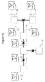
- Beacon apparatus 200 will attempt to broadcast its version of the call list to the other members of the beacon group via its radio-frequency transceiver.
- This initial message is illustrated with an exemplary type field value of "M1". It may be advantageous to detect, later on, whether subsequent messages belong to a distribution flow set up by this particular beacon apparatus 200. While this detection may be performed on the basis of a message identifier, it is also possible to include an identifier of the initiating beacon apparatus in the M1 message and the subsequent messages. This element is shown as the "Initiator" field in the figures.
- beacon apparatus 200 will reach neighboring beacon apparatus 201, 204 (these beacon apparatus are referred to as the "second beacon apparatus" in the description of claimed method).
- neighboring beacon apparatus 201, 204 receives the broadcast, it will verify whether the broadcast pertains to its beacon group and, if so, it will relay the message with the call list via its own radio-frequency transceiver to the next neighbors in range 202, 203.
- beacon apparatus may be configured to relay call list messages regardless of whether they are from a beacon apparatus in the same beacon group, to improve the chances of actually reaching all members of the beacon group; in that case, it is preferred to limit the total number of permitted relay hops (e.g., by including a "time-to-live” field in the message, which gets decremented on every relay hop), to avoid flooding the entire facility's network with messages.
- the relayed messages are illustrated with an exemplary type field value of "M2".
- a beacon apparatus that processes the call list may update the call list by adding locally stored call list information, insofar as it is able to ascertain that its locally stored information is up to date (for instance, on the basis of optional timestamps included with the call and clearance events stored in the relayed call list), so as to ensure that the most complete and up-to-date version of the call list is relayed.
- each beacon apparatus that passes on the message preferably keeps track of the messages it has already relayed - all call list messages preferably carry a unique identification number for this purpose (shown as the "Id" field in Figures 4a-4c ).
- the call list messages preferably carry a "Seen by" field, which is updated upon every relaying step.
- the "Seen by" field may take the form of a bit map, in which each member of the beacon group has a pre-assigned bit position, which it sets when it processes the message (shown as the "Seen by" field in Figures 4a-4c ).
- beacon apparatus Whenever one of the beacons of the beacon group transmits a call list message via its radio-frequency transceiver, it will be able to detect via that same radio-frequency transceiver whether any neighboring beacon apparatus passes the message on. If the beacon apparatus that initiates the distribution detects that its message is not being relayed, it may conclude that it is isolated, and may switch to fully local operation, which may include emitting visual and auditory signals to attract attention from personnel.
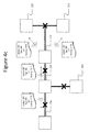
- a downstream beacon apparatus i.e., a "third beacon apparatus”
- a third beacon apparatus detects that its message is not being relayed, it may conclude that it is the last node of a sector of the network. In the illustrated example, this is the case for beacon apparatus 202, 203, and 204. In that case, the beacon apparatus starts a reverse ripple communication, with a view to distributing the "Seen by" information back to the originating beacon. This reverse ripple is illustrated in Figure 4b .
- the end point messages of the reverse ripple contain a reference to the unique identification of the original call list message (shown as the "Id" field in Figure 4b , which is identical to that of Figure 4a ), and a message type indication that distinguishes it from the latter (shown in Figure 4b as a type field with an exemplary value of "M3", which is different from that of Figure 4a ).
- the updated call list should also be included in the upstream ripple messages (not illustrated).
- the reverse ripple consists of the original end point messages, and corresponding M3 messages relayed by the beacon apparatus upstream from the end points (these beacon apparatus are referred to as the "fourth beacon apparatus"). In the illustrated example, this is the case for beacon apparatus 201 and 204. Optionally, there may be further relaying steps by beacon apparatus that received the aforementioned corresponding M3 messages (these beacon apparatus are referred to as the "fifth beacon apparatus").
- the beacon apparatus may merge these messages (for instance by applying an OR operation to the respective bitmaps), and relay the result.
- this is the case for beacon apparatus 201, which receives reports from beacon apparatus 202 and 203.
- the updated call lists may be merged in the same way (not illustrated).
- a third ripple is started to distribute the combined "Seen by" field, and optionally, the updated call list, to all members of the beacon group.
- This third ripple is illustrated in Figure 4c .
- the third ripple message contains a reference to the unique identification of the original call list message (shown as the "Id" field in Figure 4c , which is identical to that of Figures 4a and 4b ), and a message type indication that distinguishes it from the latter (shown in Figure 4c as a type field value of "M4", which is different from that of Figures 4a and 4b ).
- beacon apparatus Only after this third ripple has taken place, all beacon apparatus will be able to (1) present an up-to-date call list to any member of personnel checking in at that beacon apparatus, and (2) confirm that the list is indeed complete, by indicating that all beacon group members have processed the call list message. If any beacon group member is missing from the "seen-by" list, the checked beacon will also be able to give an indication of that fact, which will allow personnel to treat the missing beacon apparatus as isolated.
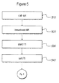
- a call list update distribution is triggered by the occurrence of a new call 510.
- the beacon apparatus at which the call is set initiates the downstream ripple by broadcasting 520 a call list update message of the first type (M1). Upon sending this message, it sets a time-out T1, sets flag F1, and listens for relaying of its message by neighboring beacon apparatus. If no relaying is detected by the expiry of T1, the originating beacon apparatus decides that it is isolated.
- a regime change 610 takes place, for instance a timed regime change which occurs without human intervention.
- a pre-designated member of the beacon group initiates 620 the distribution of the then-current call list.
- the distribution happens through the ripple message protocol 630 described above, with a message such as or similar to the M1 message described above, using a "Seen by" field whose size reflects the new composition of the beacon group, whereby it may again be useful to allow downstream beacon apparatus to modify the call list under relay, to facilitate the merging of call lists of previously separate beacon groups.
- Figure 7 schematically illustrates the processing carried out by an exemplary beacon apparatus according to an embodiment of the present invention, upon receipt 710 of a call list distribution message.
- the processing depends on the received message type.
- the selection of the appropriate processing is schematically illustrated as a cascade of type field evaluations 720, 730, 740, 750, but the skilled person will understand that this evaluation does not have to be implemented in a sequential manner.
- the receiving beacon apparatus will preferably assess 733 whether the message pertains to the same beacon group as the one it belongs to. If this is the case, it updates 734 the "Seen by" field, which may take the form of a bitmap as explained above. The receiving beacon apparatus then proceeds by retransmitting 735 the call list information, with the optionally updated "Seen by" field; this new message is now designated as an "M2" message. It also starts 736 a timer T1 (see also Figure 8 ).
- the receiving beacon apparatus will assess 731, preferably on the basis of a unique identifier of the message or the specific distribution flow, whether the message has been received before. If this is the case, the receiving beacon apparatus stops 732 any timer T1 that may be running with respect to that message (see below) and clears flag F1 (indicating that the beacon apparatus is not isolated). If it is not the case, the receiving beacon apparatus will preferably assess 733 whether the message pertains to the same beacon group as the one it belongs to, and proceed as described above for messages of the "M1" type.
- the receiving beacon apparatus will assess 741, preferably on the basis of a unique identifier of the message or the specific distribution flow, whether the message has been received before. If this is the case, no further action is necessary. If this is not the case, the receiving beacon apparatus starts or restarts 742 a timer T2.
- the received "M3" message is buffered 743, and its "Seen by" field is merged (e.g., by OR'ing bitmaps) 744 with the corresponding fields of other "M3" messages that may be received during the time allowed by timer T2 (see also Figure 9 ).
- the receiving beacon apparatus will assess 751, preferably on the basis of a unique identifier of the message or the specific distribution flow, whether the message has been received before. If this is the case, the receiving beacon apparatus evaluates 752 the call list, and thenceforth uses this call list to display the relevant information to personnel that checks in at that beacon apparatus. If it is not the case, the "M4" message is retransmitted to further its distribution to the other members of the beacon group.
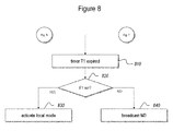
- timer T1 allows any beacon apparatus that has transmitted an M2 message to determine whether it is the last beacon apparatus in a given sector of the network.
- the timer will only be allowed to expire (without being stopped at step 732 described above), if no copies of the transmitted M2 message are received back from any neighboring beacon apparatus.
- the transmitting beacon Upon expiry 810 of the timer, the transmitting beacon checks 820 whether it is the originating beacon apparatus, as indicated by flag F1 (see Figure 5 ). If this is the case, it activates local mode 830.
- the beacon apparatus should start an upstream ripple by transmitting 840 an M3 message, which includes the most up-to-date version of the "seen by" field for that sector.
- the initial M3 message sent out by the beacon apparatus at the end of a sector is also referred to as an "end point message”.
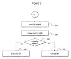
- timer T2 allows any beacon that has received an M3 message to wait for additional M3 messages before forwarding the (merged) "seen by" information along the upstream ripple.
- the receiving beacon can merge 920 the "seen by" fields of the various received M3 messages (of course, if no further M3 messages are received, no merging has to take place).
- the beacon apparatus also checks 930 whether it is the beacon that initiated this particular call list distribution flow. If that is the case, the upstream ripple has come to an end, and the beacon apparatus starts the third ripple by broadcasting 940 an M4 message. If it is not the case, the upstream ripple has to continue, and the beacon apparatus relays 950 the updated "seen by" information under the form of an M3 message.
- Figure 10 summarizes the previous figures in a single message diagram.
- the indicated reference numbers refer to the same steps as those appearing in preceding figures, but steps that are not strictly necessary to illustrate the general flow of the protocol have been omitted or simplified for clarity purposes.
- the distribution of nurse call information is assumed to start from a first beacon apparatus 200, and further interactions are limited to a second beacon apparatus 201 and a third beacon apparatus 202.
- the interaction is assumed to be triggered by the receipt of a new call 510 at the first beacon apparatus 200.
- Upon receiving that trigger it broadcasts 520 an M1 message and starts 530 timer T1.
- Timer T1 allows the beacon to detect whether the message it transmits is being redistributed by subsequent beacon apparatus.
- the M1 message is received by second beacon apparatus 201, which checks 731 if this particular M1 message (or an M2 counterpart) has been received before, finding that it hasn't. It then broadcasts 735 a corresponding M2 message and starts 736 timer T1.
- the receipt of this corresponding M2 message by the first beacon apparatus 200 causes the latter to check 731 if this M2 message has been received before and, finding that it is the counterpart of its own M1 message, to stop timer T1.
- the receipt of the M2 message by the third beacon apparatus 202 causes the latter to check 731 if this M2 message has been received before and, finding that it hasn't, broadcast 735 a corresponding M2 message and start 736 its timer T1.
- the timer T1 of further beacon apparatus 202 will expire before any further echoes of its M2 message are received.
- the expiry of timer T1 of the third beacon apparatus 202 starts the upstream part of the message flow.
- the third beacon apparatus 202 broadcasts 840 an M3 end point message.
- the receipt of the M3 end point message by the second beacon apparatus 201 causes the latter to check 741 if this M3 message has been received before and, finding that it hasn't, start 742 its timer T2, allowing it to gather further incoming M3 messages (if any) and combine them, before sending out the combined information.
- the type of the next broadcast depends 930 on whether the received M3 message(s) corresponded to an M1 message sent at the initiative of the second beacon apparatus 201.
- the second beacon apparatus 201 broadcasts 950 a (combined) M3 message.
- the receipt of that M3 message by the first beacon apparatus 200 causes the latter to check 741 if this M3 message has been received before and, finding that it hasn't, start 742 its timer T2, allowing it to gather further incoming M3 messages (if any) and combine them, before sending out the combined information.
- the type of the next broadcast again depends 930 on whether the received M3 message(s) corresponded to an M1 message sent at the initiative of the first beacon apparatus 200. Finding that this is the case, the first beacon apparatus 200 broadcasts 940 a (combined) M4 message.
- the broadcasting of the M4 message by the first beacon apparatus 200 starts the second downstream part of the message flow.
- the M4 message is received by second beacon apparatus 201, which checks 751 if this particular M4 message has been received before, finding that it hasn't. It then broadcasts 753 a corresponding M4 message.
- the corresponding M4 message is received by further beacon apparatus 202, which checks 751 if this particular M4 message has been received before, finding that it hasn't. It then again broadcasts 753 a corresponding M4 message. While the first beacon apparatus 200 and the second beacon apparatus 201 also receive the M4 messages sent by their downstream neighbors, they don't act on it, as the check 751 will reveal that they are effectively duplicates.
- the protocol can optionally be simplified in some respects.
- the information merging function ('OR' function) described above with respect to M3 messages could already be applied to the M2 messages, because many or all of the M2 messages will be received by the initiating beacon, which can therefore easily determine which other beacon apparatus have processed the original M1 message.
- the M3 messages may be skipped for this reason. For the same reason, it is not necessary to relay a message received at a beacon apparatus via a wired interface further via the same wired interface.
Landscapes
- Engineering & Computer Science (AREA)
- Business, Economics & Management (AREA)
- General Business, Economics & Management (AREA)
- Health & Medical Sciences (AREA)
- General Health & Medical Sciences (AREA)
- Epidemiology (AREA)
- Biomedical Technology (AREA)
- Medical Informatics (AREA)
- Primary Health Care (AREA)
- Public Health (AREA)
- Computer Networks & Wireless Communication (AREA)
- Signal Processing (AREA)
- Mobile Radio Communication Systems (AREA)
Priority Applications (1)
| Application Number | Priority Date | Filing Date | Title |
|---|---|---|---|
| EP15178547.4A EP2976996B1 (de) | 2014-07-25 | 2015-07-27 | Pflegerufsystem mit lokalem betriebsmodus |
Applications Claiming Priority (2)
| Application Number | Priority Date | Filing Date | Title |
|---|---|---|---|
| EP14178642.6A EP2976992B1 (de) | 2014-07-25 | 2014-07-25 | Pflegerufsystem mit lokalem betriebsmodus |
| EP15178547.4A EP2976996B1 (de) | 2014-07-25 | 2015-07-27 | Pflegerufsystem mit lokalem betriebsmodus |
Publications (2)
| Publication Number | Publication Date |
|---|---|
| EP2976996A1 true EP2976996A1 (de) | 2016-01-27 |
| EP2976996B1 EP2976996B1 (de) | 2019-05-29 |
Family
ID=51225354
Family Applications (2)
| Application Number | Title | Priority Date | Filing Date |
|---|---|---|---|
| EP14178642.6A Active EP2976992B1 (de) | 2014-07-25 | 2014-07-25 | Pflegerufsystem mit lokalem betriebsmodus |
| EP15178547.4A Active EP2976996B1 (de) | 2014-07-25 | 2015-07-27 | Pflegerufsystem mit lokalem betriebsmodus |
Family Applications Before (1)
| Application Number | Title | Priority Date | Filing Date |
|---|---|---|---|
| EP14178642.6A Active EP2976992B1 (de) | 2014-07-25 | 2014-07-25 | Pflegerufsystem mit lokalem betriebsmodus |
Country Status (1)
| Country | Link |
|---|---|
| EP (2) | EP2976992B1 (de) |
Citations (6)
| Publication number | Priority date | Publication date | Assignee | Title |
|---|---|---|---|---|
| EP1400941A2 (de) * | 2002-09-12 | 2004-03-24 | Siemens Aktiengesellschaft | Rufanlage auf Basis eines digitalen Telekommunikationsnetzes |
| US20050135236A1 (en) * | 2003-12-23 | 2005-06-23 | International Business Machines Corporation | Smart access point |
| US20090003216A1 (en) * | 2007-06-27 | 2009-01-01 | Microsoft Corporation | Multipath Forwarding Algorithms Using Network Coding |
| US20090212925A1 (en) * | 2008-02-22 | 2009-08-27 | Schuman Sr Richard Joseph | User station for healthcare communication system |
| WO2010150031A1 (en) * | 2009-06-23 | 2010-12-29 | Attila Angyal | System for locating and registration of mobile units moving in zones defined by access points |
| US20120225655A1 (en) * | 2011-03-04 | 2012-09-06 | Samsung Electronics Co. Ltd. | Apparatus and method for controlling relay mode of base station in communication system |
-
2014
- 2014-07-25 EP EP14178642.6A patent/EP2976992B1/de active Active
-
2015
- 2015-07-27 EP EP15178547.4A patent/EP2976996B1/de active Active
Patent Citations (6)
| Publication number | Priority date | Publication date | Assignee | Title |
|---|---|---|---|---|
| EP1400941A2 (de) * | 2002-09-12 | 2004-03-24 | Siemens Aktiengesellschaft | Rufanlage auf Basis eines digitalen Telekommunikationsnetzes |
| US20050135236A1 (en) * | 2003-12-23 | 2005-06-23 | International Business Machines Corporation | Smart access point |
| US20090003216A1 (en) * | 2007-06-27 | 2009-01-01 | Microsoft Corporation | Multipath Forwarding Algorithms Using Network Coding |
| US20090212925A1 (en) * | 2008-02-22 | 2009-08-27 | Schuman Sr Richard Joseph | User station for healthcare communication system |
| WO2010150031A1 (en) * | 2009-06-23 | 2010-12-29 | Attila Angyal | System for locating and registration of mobile units moving in zones defined by access points |
| US20120225655A1 (en) * | 2011-03-04 | 2012-09-06 | Samsung Electronics Co. Ltd. | Apparatus and method for controlling relay mode of base station in communication system |
Also Published As
| Publication number | Publication date |
|---|---|
| EP2976992A1 (de) | 2016-01-27 |
| EP2976992B1 (de) | 2019-12-18 |
| EP2976996B1 (de) | 2019-05-29 |
Similar Documents
| Publication | Publication Date | Title |
|---|---|---|
| US10588173B2 (en) | Wi-Fi mesh fire detection system | |
| US10660019B2 (en) | Locating physical assets via near field communication nodes | |
| US8824444B1 (en) | Null interface feature in wireless mesh networking device | |
| US20020198986A1 (en) | Location system and methods | |
| CN103517388B (zh) | Wi-Fi火灾检测系统中的接入点同步 | |
| CN106817679A (zh) | 基于无线通信技术的用于定位服务的网络系统 | |
| JP2007506308A (ja) | マイクロセルラネットワーク内の調整可能な送信電力を用いた位置特定システム | |
| JP5836183B2 (ja) | 無線通信システム、無線通信装置および基準装置 | |
| CN105282770A (zh) | 无线自愈式组网优化与自检方法 | |
| US7512406B2 (en) | Personnel tracking system | |
| CN104604183B (zh) | 使用移动通信设备发送消息的方法和系统 | |
| EP2976996A1 (de) | Pflegerufsystem mit lokalem betriebsmodus | |
| EP2978164B1 (de) | Hybrides Pflegerufsystem | |
| US20200187020A1 (en) | In-facility transmission system, in-facility transmission method, and base station | |
| JP4555782B2 (ja) | 一斉データ配信システムおよび一斉データ配信方法 | |
| JP2005354625A (ja) | マルチホップデータ転送経路構築方法、ネットワークシステム | |
| JP6957142B2 (ja) | 制御装置、無線通信装置及びチャネル制御方法 | |
| CN114710305A (zh) | 数据处理方法、装置、计算机可读存储介质和处理器 | |
| JPWO2002035868A1 (ja) | 移動通信装置及びシステム | |
| JP6064198B2 (ja) | 無線ネットワークシステム、及びこれを用いた安否確認システム | |
| CN120416789A (zh) | 一种基于星闪技术的医疗控制系统 | |
| JP2000049838A (ja) | アラーム収集システム及びその収集方法 | |
| HK1238840B (zh) | 基於无线通信技术的用於定位服务的网络系统 | |
| KR20070020379A (ko) | 마이크로 셀룰러 네트워크에서 조정가능한 송신 전력을이용한 위치결정 시스템 | |
| JP2013205064A (ja) | 位置測定システム及び位置測定方法 |
Legal Events
| Date | Code | Title | Description |
|---|---|---|---|
| PUAI | Public reference made under article 153(3) epc to a published international application that has entered the european phase |
Free format text: ORIGINAL CODE: 0009012 |
|
| AK | Designated contracting states |
Kind code of ref document: A1 Designated state(s): AL AT BE BG CH CY CZ DE DK EE ES FI FR GB GR HR HU IE IS IT LI LT LU LV MC MK MT NL NO PL PT RO RS SE SI SK SM TR |
|
| AX | Request for extension of the european patent |
Extension state: BA ME |
|
| 17P | Request for examination filed |
Effective date: 20160719 |
|
| RBV | Designated contracting states (corrected) |
Designated state(s): AL AT BE BG CH CY CZ DE DK EE ES FI FR GB GR HR HU IE IS IT LI LT LU LV MC MK MT NL NO PL PT RO RS SE SI SK SM TR |
|
| REG | Reference to a national code |
Ref country code: DE Ref legal event code: R079 Ref document number: 602015031051 Country of ref document: DE Free format text: PREVIOUS MAIN CLASS: A61B0005000000 Ipc: G06F0019000000 |
|
| GRAP | Despatch of communication of intention to grant a patent |
Free format text: ORIGINAL CODE: EPIDOSNIGR1 |
|
| STAA | Information on the status of an ep patent application or granted ep patent |
Free format text: STATUS: GRANT OF PATENT IS INTENDED |
|
| RIC1 | Information provided on ipc code assigned before grant |
Ipc: G06F 19/00 20180101AFI20181210BHEP Ipc: H04W 68/00 20090101ALI20181210BHEP Ipc: A61B 5/00 20060101ALN20181210BHEP Ipc: H04W 88/04 20090101ALN20181210BHEP |
|
| INTG | Intention to grant announced |
Effective date: 20190107 |
|
| RIN1 | Information on inventor provided before grant (corrected) |
Inventor name: VERHAEGHE, GEERT Inventor name: DESMET, LUDWIG Inventor name: CROMBEZ, PIETER Inventor name: GESQUIERE, JOHN |
|
| GRAS | Grant fee paid |
Free format text: ORIGINAL CODE: EPIDOSNIGR3 |
|
| GRAA | (expected) grant |
Free format text: ORIGINAL CODE: 0009210 |
|
| STAA | Information on the status of an ep patent application or granted ep patent |
Free format text: STATUS: THE PATENT HAS BEEN GRANTED |
|
| AK | Designated contracting states |
Kind code of ref document: B1 Designated state(s): AL AT BE BG CH CY CZ DE DK EE ES FI FR GB GR HR HU IE IS IT LI LT LU LV MC MK MT NL NO PL PT RO RS SE SI SK SM TR |
|
| REG | Reference to a national code |
Ref country code: GB Ref legal event code: FG4D |
|
| REG | Reference to a national code |
Ref country code: CH Ref legal event code: EP |
|
| REG | Reference to a national code |
Ref country code: AT Ref legal event code: REF Ref document number: 1138695 Country of ref document: AT Kind code of ref document: T Effective date: 20190615 |
|
| REG | Reference to a national code |
Ref country code: DE Ref legal event code: R096 Ref document number: 602015031051 Country of ref document: DE |
|
| REG | Reference to a national code |
Ref country code: IE Ref legal event code: FG4D |
|
| REG | Reference to a national code |
Ref country code: NL Ref legal event code: FP |
|
| REG | Reference to a national code |
Ref country code: LT Ref legal event code: MG4D |
|
| PG25 | Lapsed in a contracting state [announced via postgrant information from national office to epo] |
Ref country code: SE Free format text: LAPSE BECAUSE OF FAILURE TO SUBMIT A TRANSLATION OF THE DESCRIPTION OR TO PAY THE FEE WITHIN THE PRESCRIBED TIME-LIMIT Effective date: 20190529 Ref country code: PT Free format text: LAPSE BECAUSE OF FAILURE TO SUBMIT A TRANSLATION OF THE DESCRIPTION OR TO PAY THE FEE WITHIN THE PRESCRIBED TIME-LIMIT Effective date: 20190930 Ref country code: LT Free format text: LAPSE BECAUSE OF FAILURE TO SUBMIT A TRANSLATION OF THE DESCRIPTION OR TO PAY THE FEE WITHIN THE PRESCRIBED TIME-LIMIT Effective date: 20190529 Ref country code: AL Free format text: LAPSE BECAUSE OF FAILURE TO SUBMIT A TRANSLATION OF THE DESCRIPTION OR TO PAY THE FEE WITHIN THE PRESCRIBED TIME-LIMIT Effective date: 20190529 Ref country code: NO Free format text: LAPSE BECAUSE OF FAILURE TO SUBMIT A TRANSLATION OF THE DESCRIPTION OR TO PAY THE FEE WITHIN THE PRESCRIBED TIME-LIMIT Effective date: 20190829 Ref country code: ES Free format text: LAPSE BECAUSE OF FAILURE TO SUBMIT A TRANSLATION OF THE DESCRIPTION OR TO PAY THE FEE WITHIN THE PRESCRIBED TIME-LIMIT Effective date: 20190529 Ref country code: HR Free format text: LAPSE BECAUSE OF FAILURE TO SUBMIT A TRANSLATION OF THE DESCRIPTION OR TO PAY THE FEE WITHIN THE PRESCRIBED TIME-LIMIT Effective date: 20190529 Ref country code: FI Free format text: LAPSE BECAUSE OF FAILURE TO SUBMIT A TRANSLATION OF THE DESCRIPTION OR TO PAY THE FEE WITHIN THE PRESCRIBED TIME-LIMIT Effective date: 20190529 |
|
| PG25 | Lapsed in a contracting state [announced via postgrant information from national office to epo] |
Ref country code: BG Free format text: LAPSE BECAUSE OF FAILURE TO SUBMIT A TRANSLATION OF THE DESCRIPTION OR TO PAY THE FEE WITHIN THE PRESCRIBED TIME-LIMIT Effective date: 20190829 Ref country code: RS Free format text: LAPSE BECAUSE OF FAILURE TO SUBMIT A TRANSLATION OF THE DESCRIPTION OR TO PAY THE FEE WITHIN THE PRESCRIBED TIME-LIMIT Effective date: 20190529 Ref country code: LV Free format text: LAPSE BECAUSE OF FAILURE TO SUBMIT A TRANSLATION OF THE DESCRIPTION OR TO PAY THE FEE WITHIN THE PRESCRIBED TIME-LIMIT Effective date: 20190529 Ref country code: GR Free format text: LAPSE BECAUSE OF FAILURE TO SUBMIT A TRANSLATION OF THE DESCRIPTION OR TO PAY THE FEE WITHIN THE PRESCRIBED TIME-LIMIT Effective date: 20190830 |
|
| REG | Reference to a national code |
Ref country code: AT Ref legal event code: MK05 Ref document number: 1138695 Country of ref document: AT Kind code of ref document: T Effective date: 20190529 |
|
| PG25 | Lapsed in a contracting state [announced via postgrant information from national office to epo] |
Ref country code: AT Free format text: LAPSE BECAUSE OF FAILURE TO SUBMIT A TRANSLATION OF THE DESCRIPTION OR TO PAY THE FEE WITHIN THE PRESCRIBED TIME-LIMIT Effective date: 20190529 Ref country code: EE Free format text: LAPSE BECAUSE OF FAILURE TO SUBMIT A TRANSLATION OF THE DESCRIPTION OR TO PAY THE FEE WITHIN THE PRESCRIBED TIME-LIMIT Effective date: 20190529 Ref country code: DK Free format text: LAPSE BECAUSE OF FAILURE TO SUBMIT A TRANSLATION OF THE DESCRIPTION OR TO PAY THE FEE WITHIN THE PRESCRIBED TIME-LIMIT Effective date: 20190529 Ref country code: SK Free format text: LAPSE BECAUSE OF FAILURE TO SUBMIT A TRANSLATION OF THE DESCRIPTION OR TO PAY THE FEE WITHIN THE PRESCRIBED TIME-LIMIT Effective date: 20190529 Ref country code: CZ Free format text: LAPSE BECAUSE OF FAILURE TO SUBMIT A TRANSLATION OF THE DESCRIPTION OR TO PAY THE FEE WITHIN THE PRESCRIBED TIME-LIMIT Effective date: 20190529 Ref country code: RO Free format text: LAPSE BECAUSE OF FAILURE TO SUBMIT A TRANSLATION OF THE DESCRIPTION OR TO PAY THE FEE WITHIN THE PRESCRIBED TIME-LIMIT Effective date: 20190529 |
|
| PG25 | Lapsed in a contracting state [announced via postgrant information from national office to epo] |
Ref country code: MC Free format text: LAPSE BECAUSE OF FAILURE TO SUBMIT A TRANSLATION OF THE DESCRIPTION OR TO PAY THE FEE WITHIN THE PRESCRIBED TIME-LIMIT Effective date: 20190529 Ref country code: SM Free format text: LAPSE BECAUSE OF FAILURE TO SUBMIT A TRANSLATION OF THE DESCRIPTION OR TO PAY THE FEE WITHIN THE PRESCRIBED TIME-LIMIT Effective date: 20190529 |
|
| REG | Reference to a national code |
Ref country code: CH Ref legal event code: PL |
|
| REG | Reference to a national code |
Ref country code: DE Ref legal event code: R097 Ref document number: 602015031051 Country of ref document: DE |
|
| PG25 | Lapsed in a contracting state [announced via postgrant information from national office to epo] |
Ref country code: TR Free format text: LAPSE BECAUSE OF FAILURE TO SUBMIT A TRANSLATION OF THE DESCRIPTION OR TO PAY THE FEE WITHIN THE PRESCRIBED TIME-LIMIT Effective date: 20190529 |
|
| PLBE | No opposition filed within time limit |
Free format text: ORIGINAL CODE: 0009261 |
|
| STAA | Information on the status of an ep patent application or granted ep patent |
Free format text: STATUS: NO OPPOSITION FILED WITHIN TIME LIMIT |
|
| GBPC | Gb: european patent ceased through non-payment of renewal fee |
Effective date: 20190829 |
|
| PG25 | Lapsed in a contracting state [announced via postgrant information from national office to epo] |
Ref country code: PL Free format text: LAPSE BECAUSE OF FAILURE TO SUBMIT A TRANSLATION OF THE DESCRIPTION OR TO PAY THE FEE WITHIN THE PRESCRIBED TIME-LIMIT Effective date: 20190529 |
|
| 26N | No opposition filed |
Effective date: 20200303 |
|
| PG25 | Lapsed in a contracting state [announced via postgrant information from national office to epo] |
Ref country code: SI Free format text: LAPSE BECAUSE OF FAILURE TO SUBMIT A TRANSLATION OF THE DESCRIPTION OR TO PAY THE FEE WITHIN THE PRESCRIBED TIME-LIMIT Effective date: 20190529 Ref country code: LI Free format text: LAPSE BECAUSE OF NON-PAYMENT OF DUE FEES Effective date: 20190731 Ref country code: CH Free format text: LAPSE BECAUSE OF NON-PAYMENT OF DUE FEES Effective date: 20190731 Ref country code: LU Free format text: LAPSE BECAUSE OF NON-PAYMENT OF DUE FEES Effective date: 20190727 |
|
| PG25 | Lapsed in a contracting state [announced via postgrant information from national office to epo] |
Ref country code: IE Free format text: LAPSE BECAUSE OF NON-PAYMENT OF DUE FEES Effective date: 20190727 |
|
| PG25 | Lapsed in a contracting state [announced via postgrant information from national office to epo] |
Ref country code: GB Free format text: LAPSE BECAUSE OF NON-PAYMENT OF DUE FEES Effective date: 20190829 |
|
| PG25 | Lapsed in a contracting state [announced via postgrant information from national office to epo] |
Ref country code: CY Free format text: LAPSE BECAUSE OF FAILURE TO SUBMIT A TRANSLATION OF THE DESCRIPTION OR TO PAY THE FEE WITHIN THE PRESCRIBED TIME-LIMIT Effective date: 20190529 |
|
| PG25 | Lapsed in a contracting state [announced via postgrant information from national office to epo] |
Ref country code: IS Free format text: LAPSE BECAUSE OF FAILURE TO SUBMIT A TRANSLATION OF THE DESCRIPTION OR TO PAY THE FEE WITHIN THE PRESCRIBED TIME-LIMIT Effective date: 20190929 |
|
| PG25 | Lapsed in a contracting state [announced via postgrant information from national office to epo] |
Ref country code: MT Free format text: LAPSE BECAUSE OF FAILURE TO SUBMIT A TRANSLATION OF THE DESCRIPTION OR TO PAY THE FEE WITHIN THE PRESCRIBED TIME-LIMIT Effective date: 20190529 Ref country code: HU Free format text: LAPSE BECAUSE OF FAILURE TO SUBMIT A TRANSLATION OF THE DESCRIPTION OR TO PAY THE FEE WITHIN THE PRESCRIBED TIME-LIMIT; INVALID AB INITIO Effective date: 20150727 |
|
| PG25 | Lapsed in a contracting state [announced via postgrant information from national office to epo] |
Ref country code: MK Free format text: LAPSE BECAUSE OF FAILURE TO SUBMIT A TRANSLATION OF THE DESCRIPTION OR TO PAY THE FEE WITHIN THE PRESCRIBED TIME-LIMIT Effective date: 20190529 |
|
| P01 | Opt-out of the competence of the unified patent court (upc) registered |
Effective date: 20230602 |
|
| REG | Reference to a national code |
Ref country code: NL Ref legal event code: PD Owner name: TELEVIC CONFERENCE N.V.; BE Free format text: DETAILS ASSIGNMENT: CHANGE OF OWNER(S), DEMERGER; FORMER OWNER NAME: TELEVIC HEALTHCARE NV Effective date: 20250124 Ref country code: NL Ref legal event code: HC Owner name: TELEVIC N.V.; BE Free format text: DETAILS ASSIGNMENT: CHANGE OF OWNER(S), CHANGE OF OWNER(S) NAME; FORMER OWNER NAME: TELEVIC CONFERENCE N.V. Effective date: 20250124 |
|
| REG | Reference to a national code |
Ref country code: DE Ref legal event code: R082 Ref document number: 602015031051 Country of ref document: DE Representative=s name: BECK, MICHAEL ANDRIES, BE Ref country code: DE Ref legal event code: R081 Ref document number: 602015031051 Country of ref document: DE Owner name: TELEVIC N.V., BE Free format text: FORMER OWNER: TELEVIC HEALTHCARE NV, IZEGEM, BE |
|
| REG | Reference to a national code |
Ref country code: BE Ref legal event code: HC Owner name: TELEVIC N.V.; BE Free format text: DETAILS ASSIGNMENT: CHANGE OF OWNER(S), CHANGE OF OWNER(S) NAME; FORMER OWNER NAME: TELEVIC CONFERENCE NV Effective date: 20250124 Ref country code: BE Ref legal event code: PD Owner name: TELEVIC CONFERENCE NV; BE Free format text: DETAILS ASSIGNMENT: CHANGE OF OWNER(S), ASSIGNMENT; FORMER OWNER NAME: TELEVIC HEALTHCARE NV Effective date: 20250124 |
|
| PGFP | Annual fee paid to national office [announced via postgrant information from national office to epo] |
Ref country code: NL Payment date: 20250704 Year of fee payment: 11 |
|
| PGFP | Annual fee paid to national office [announced via postgrant information from national office to epo] |
Ref country code: DE Payment date: 20250722 Year of fee payment: 11 |
|
| PGFP | Annual fee paid to national office [announced via postgrant information from national office to epo] |
Ref country code: IT Payment date: 20250724 Year of fee payment: 11 |
|
| PGFP | Annual fee paid to national office [announced via postgrant information from national office to epo] |
Ref country code: BE Payment date: 20250704 Year of fee payment: 11 |
|
| PGFP | Annual fee paid to national office [announced via postgrant information from national office to epo] |
Ref country code: FR Payment date: 20250725 Year of fee payment: 11 |