EP1400941A2 - Rufanlage auf Basis eines digitalen Telekommunikationsnetzes - Google Patents
Rufanlage auf Basis eines digitalen Telekommunikationsnetzes Download PDFInfo
- Publication number
- EP1400941A2 EP1400941A2 EP03020348A EP03020348A EP1400941A2 EP 1400941 A2 EP1400941 A2 EP 1400941A2 EP 03020348 A EP03020348 A EP 03020348A EP 03020348 A EP03020348 A EP 03020348A EP 1400941 A2 EP1400941 A2 EP 1400941A2
- Authority
- EP
- European Patent Office
- Prior art keywords
- call
- switching system
- unit
- terminal
- application server
- Prior art date
- Legal status (The legal status is an assumption and is not a legal conclusion. Google has not performed a legal analysis and makes no representation as to the accuracy of the status listed.)
- Granted
Links
Images
Classifications
-
- H—ELECTRICITY
- H04—ELECTRIC COMMUNICATION TECHNIQUE
- H04L—TRANSMISSION OF DIGITAL INFORMATION, e.g. TELEGRAPHIC COMMUNICATION
- H04L43/00—Arrangements for monitoring or testing data switching networks
- H04L43/50—Testing arrangements
-
- G—PHYSICS
- G08—SIGNALLING
- G08B—SIGNALLING OR CALLING SYSTEMS; ORDER TELEGRAPHS; ALARM SYSTEMS
- G08B25/00—Alarm systems in which the location of the alarm condition is signalled to a central station, e.g. fire or police telegraphic systems
- G08B25/01—Alarm systems in which the location of the alarm condition is signalled to a central station, e.g. fire or police telegraphic systems characterised by the transmission medium
- G08B25/016—Personal emergency signalling and security systems
-
- G—PHYSICS
- G08—SIGNALLING
- G08B—SIGNALLING OR CALLING SYSTEMS; ORDER TELEGRAPHS; ALARM SYSTEMS
- G08B25/00—Alarm systems in which the location of the alarm condition is signalled to a central station, e.g. fire or police telegraphic systems
- G08B25/01—Alarm systems in which the location of the alarm condition is signalled to a central station, e.g. fire or police telegraphic systems characterised by the transmission medium
- G08B25/08—Alarm systems in which the location of the alarm condition is signalled to a central station, e.g. fire or police telegraphic systems characterised by the transmission medium using communication transmission lines
-
- G—PHYSICS
- G08—SIGNALLING
- G08B—SIGNALLING OR CALLING SYSTEMS; ORDER TELEGRAPHS; ALARM SYSTEMS
- G08B29/00—Checking or monitoring of signalling or alarm systems; Prevention or correction of operating errors, e.g. preventing unauthorised operation
- G08B29/02—Monitoring continuously signalling or alarm systems
- G08B29/06—Monitoring of the line circuits, e.g. signalling of line faults
Definitions
- the invention relates to a call system, as for example as an emergency or nursing call system in a nursing home, Retirement home or hospital is used.
- the invention has for its object an inexpensive Specify call system that meets the requirements specified in particular in accordance with VDE 0834 meets the required security requirements.
- the call system then includes a digital Switching system, on the one hand, for data transfer with a terminal, and on the other hand with an application server is connected, the terminal being a call triggering unit to generate an emergency call.
- the switching system is still connected to a monitoring unit, which periodically sends test data to the application server and one if the test data is not properly acknowledged Error detector activated.
- a call system can be implemented particularly inexpensively on the basis of a conventional digital telecommunications system (PBX), for example according to the IDSN or U P0 / E standard.
- PBX digital telecommunications system
- Such a PBX such as that manufactured by Siemens under the type designation HiPATH, usually comprises several terminal devices (for example telephones, fax machines, etc.) connected in a star configuration to a switching system and one or more computers with application software. This or these application servers take over, for example, the billing.
- Telecommunications technology is comparatively inexpensive on the one hand, since such systems are used not only for the care sector, but also in large numbers in the private and industrial sector. On the other hand, in most nursing homes, etc., a PBX is provided anyway.
- the switching system itself must therefore comply with that of the VDE 0834 required safety standard and can not therefore by a comparatively inexpensive, conventional Switching system can be realized.
- the line also monitors the monitoring unit Application server, especially since the test data is only acknowledged if the application server is running properly.
- the call release unit comprises one Interface unit that is connected to a call trigger.
- An interface unit is understood to be a device that stores data Exchange with the digital switching system without conflict can and the means for generating and / or reproducing such Data.
- Such a connection device is in principle present in a digital phone.
- the call trigger is, for example a function key on the phone, by pressing it Emergency or nursing call is triggered. Equivalently, can however, the call trigger is also arranged externally and with the interface unit via a call line led out of the terminal be connected.
- the interface unit can continue Be part of a so-called "room connection", the call function includes, i.A. but not for voice recording and / or playback is equipped.
- This call line and thus the call trigger, is preferably monitored by a loop current. That is, through the Call line a continuous test current flows which indicates that the line is not interrupted.
- a call detector connected to the terminal serves on the one hand to display the emergency call directly.
- the call detector is there preferably by a well known from hospitals Realized room light. Alternatively or additionally takes place also use an acoustic call detector. Still guaranteed the call detector connected directly to the interface unit, that the emergency call should the switching system fail or the application server is displayed at least locally becomes.
- the switching system and the terminal are preferably connected via a digital telephone interface, for example U P0 / E or an S 0 bus.
- a digital telephone interface for example U P0 / E or an S 0 bus.
- These digital telephone interfaces are internationally standardized and serve as a standard connection for digital devices.
- the data transfer between the switching system and the application server is advantageously based on the TCP / IP standard. This protocol is well known for data transmission in computer networks. Conventional switching systems are often even equipped with TCP / IP-capable interfaces as standard.
- a second connection unit connected to the switching system allows easy connection of the monitoring unit to the switching system. A possible failure the monitoring unit and the connection is standard detected by the switching system.
- the monitoring unit is an inexpensive and extremely compact design by a microcontroller, i.e. through a Semiconductor chip, realized. Especially in this form the monitoring unit is preferably integrated directly into the terminal. This allows a particularly simple retrofit ordinary PBX to a standardized call system, especially to the PBX, only a terminal device according to the invention and if necessary a server must be connected.
- the call system expediently comprises several such terminals, each of which is a call triggering unit and a monitoring unit contains.
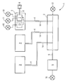
- the core of a call system 1 shown in a highly simplified manner is a digital switching system 2.
- the switching system 2 is connected in a star shape to a plurality of terminals 3, 3 ', of which only the terminal 3 is designed in more detail.
- the identical end devices 3 ' are only indicated for reasons of simplification.
- the data lines 4 connecting each terminal 3, 3 'to the switching system 2 are designed in accordance with the technology customary in a digital system by SO or U P0 / E interfaces.
- the switching system 2 is still connected to an application server 6 via a LAN line 5.
- the LAN line 5 is implemented in a technology that is customary for an ordinary LAN (local area network) computer network.
- the data transfer between the switching system 2 and the application server 6 is based on the TCP / IP standard, which is widespread in computer networks.
- the basic function of call system 1 is an ordinary digital telecommunications (PBX) system, in particular a Siemens Hi-PATH system with U P0 / E interfaces.
- PBX ordinary digital telecommunications
- the terminal 3 is provided with a first connection unit 7, which can exchange data with the switching system 2, and which is connected to a loudspeaker, a microphone and a keypad for data input and output in a manner not shown. Normal telephone calls can thus be made via the terminal 3.
- a so-called "room connection” is provided as the terminal 3, in which the terminal 3 is not equipped with a speech function.
- the interface unit is used to trigger an emergency or care call 7 connected to a call trigger via a call line 8, which is formed by a release button 9.
- the interface unit 7, the call line 8 and the trigger button 9 thus form a call trigger unit.
- the release button 9 can be one of the function keys of the terminal 3 or - how shown - be arranged outside the terminal 3.
- Call indicator 10 actuated.
- this serves as call indicator 10 a room light common in hospitals and nursing homes. Additional light signals, e.g. in one Ward room, as well as an acoustic call signal activated.
- the interface unit 7 transmits a call signal the data line 4 to the switching system 2, from where the Call forwarded via the LAN line 5 to the application server 6 becomes.
- Call control system will now trigger further steps such as. the transmission of the emergency or nursing call as call forwarding to a further terminal 3 '.
- Can continue other reporting systems such as DECT terminals, people search devices, Devices etc. accessible via exchange lines are activated.
- the call line 8 monitored loop current. This means that regardless of the current operating state of the release button 9 a continuous test current through the call line 8 and the release button 9 is passed.
- a loop current monitor is technically realized, for example, that the switching contact, not shown, the Trigger button 9 a high resistance is connected in parallel, over which the test current flows.
- a malfunction inside the call line 8 is recognized by the connection unit 7 that the test current is interrupted.
- the activation unit 7 activates an error detector 11 which as the call indicator 10, by a light and / or sound signal realized and can also be integrated in the call detector 10.
- the Data line 4 is both standard in the PBX on the part of the connection unit 7 and on the part of the switching system 2 constantly monitored by periodically sending telegrams between the connection unit 7 and the switching system 2 be replaced. If the acknowledgment is not correct the telegrams sent by the interface unit 7 are activated this in turn the error detector 11, so that an interruption the data line 4 or a failure of the switching system 2 is displayed. The switching system is also activated 2 in the event of incorrect acknowledgment of the by the switching system 2 sent to the interface unit 7 Telegrams connected to the switching system 2 Error detector 12 and thus reports an interruption in the data line 4 or the failure of the interface unit 7.
- a second connection unit 13 is provided.
- the interface unit 13 is also via a digital telephone interface executed test line 14 with the switching system 2 connected.
- the connection unit 13 is like that Interface unit 7 according to digital TC technology for data exchange provided with the switching system 2.
- the interface unit 13, the so-called "embedded technology” is designed as a microchip, is configured such that that they periodically test data via the test line 14, the Switching system 2 and the LAN line 5 to the application server 6 sends and the acknowledgment of this test data supervised.
- the functions of the interface units 7 and 13 can also be used as software modules on a single controller card be provided.
- the data line 4 and the test line 14 are generally not physically separated.
- connection unit 13 The proper acknowledgment of the connection unit 13 sent test data requires that the test line 14, the switching system 2, the LAN line 5 and the application server 6 work correctly. If not If so, the connection unit 13 activates another one Error detector 15. A failure of the connection unit 13 in turn is recognized by switching system 2 as standard. Malfunctions within the application server 6 are also from the application server 6 via one with this connected error indicator 16 is displayed.
- the entire message path is from the trigger button 9 via the connection unit 7, the data line 4, the switching system 2, the LAN line 5 to the application server 6 monitored in a redundant manner.
- the safety requirements of VDE 0834 In case of an error part of the error indicators 11, 12, 15 and 16 becomes more characteristic Way activated so that about this characteristic Error display pattern quickly locates the source of the error is.
Landscapes
- Engineering & Computer Science (AREA)
- General Physics & Mathematics (AREA)
- Physics & Mathematics (AREA)
- Computer Security & Cryptography (AREA)
- Business, Economics & Management (AREA)
- Emergency Management (AREA)
- Signal Processing (AREA)
- Computer Networks & Wireless Communication (AREA)
- Telephonic Communication Services (AREA)
- Sub-Exchange Stations And Push- Button Telephones (AREA)
- Monitoring And Testing Of Exchanges (AREA)
- Exchange Systems With Centralized Control (AREA)
- Mobile Radio Communication Systems (AREA)
- Maintenance And Management Of Digital Transmission (AREA)
- Arrangements For Transmission Of Measured Signals (AREA)
Abstract
Description
Claims (11)
- Rufanlage (1) mit einer digitalen Vermittlungsanlage (2), die einerseits mit einem eine Rufauslöseeinheit (7,8,9) umfassenden Endgerät (3,3`), und andererseits mit einem Applikations-Server (6) datentransfermäßig verbunden ist, wobei die Vermittlungsanlage (2) weiterhin mit einer Überwachungseinheit (13) verbunden ist, welche periodisch Prüfdaten an den Applikations-Server (6) sendet und bei nicht ordnungsgemäßer Quittierung der Prüfdaten einen Fehlermelder (15) aktiviert.
- Rufanlage nach Anspruch 1, dadurch gekennzeichnet, dass die Rufauslöseeinheit eine mit einem Rufauslöser (9) verbundene erste Anschalteeinheit (7) umfasst.
- Rufanlage nach Anspruch 2, dadurch gekennzeichnet , dass die Anschalteeinheit (7) und der Rufauslöser (9) über eine schleifenstromüberwachte Rufleitung (8) verbunden sind.
- Rufanlage nach einem der Ansprüche 1 bis 3, dadurch gekennzeichnet , dass das Endgerät (3, 3') mit einem Rufmelder (10) verbunden ist, der durch Betätigung der Rufauslöseeinheit (9) aktivierbar ist.
- Rufanlage nach einem der Ansprüche 1 bis 4, dadurch gekennzeichnet , dass die Vermittlungsanlage (2) und das Endgerät (3, 3') über eine digitale Telefonschnittstelle verbunden sind.
- Rufanlage nach einem der Ansprüche 1 bis 5, dadurch gekennzeichnet, dass der Datentransfer zwischen der Vermittlungsanlage (2) und dem Applikations-Server (6) auf dem TCP/IP-Standard beruht.
- Rufanlage nach einem der Ansprüche 1 bis 6, dadurch gekennzeichnet, dass die Überwachungseinheit durch eine zweite, mit der Vermittlungsanlage (2) verbundene Anschalteeinheit (13) gebildet ist.
- Rufanlage nach einem der Ansprüche 1 bis 7, dadurch gekennzeichnet, dass die Überwachungseinheit (13) als Mikrocontroller in Form eines Halbleiterbauteils ausgebildet ist.
- Rufanlage nach einem Ansprüche 1 bis 8, dadurch gekennzeichnet, dass die Überwachungseinheit (13) im Endgerät (3, 3') integriert ist .
- Rufanlage nach Anspruch 9, gekennzeichnet durch mehrere mit der Vermittlungsanlage (2) verbundene Endgeräte (3, 3').
- Rufanlage nach einem der Ansprüche 1 bis 10, dadurch gekennzeichnet , dass die Vermittlungsanlage (2) eine digitale Telekommunikationsanlage ist.
Applications Claiming Priority (2)
| Application Number | Priority Date | Filing Date | Title |
|---|---|---|---|
| DE10242534A DE10242534A1 (de) | 2002-09-12 | 2002-09-12 | Rufanlage auf Basis einer digitalen Telekommunikationsanlage |
| DE10242534 | 2002-09-12 |
Publications (3)
| Publication Number | Publication Date |
|---|---|
| EP1400941A2 true EP1400941A2 (de) | 2004-03-24 |
| EP1400941A3 EP1400941A3 (de) | 2004-07-21 |
| EP1400941B1 EP1400941B1 (de) | 2009-03-11 |
Family
ID=31895935
Family Applications (1)
| Application Number | Title | Priority Date | Filing Date |
|---|---|---|---|
| EP03020348A Expired - Lifetime EP1400941B1 (de) | 2002-09-12 | 2003-09-09 | Rufanlage auf Basis eines digitalen Telekommunikationsnetzes |
Country Status (3)
| Country | Link |
|---|---|
| EP (1) | EP1400941B1 (de) |
| AT (1) | ATE425524T1 (de) |
| DE (2) | DE10242534A1 (de) |
Cited By (3)
| Publication number | Priority date | Publication date | Assignee | Title |
|---|---|---|---|---|
| EP2006816A1 (de) * | 2007-06-18 | 2008-12-24 | Siemens Aktiengesellschaft | Rufanlage für eine Betreuungseinrichtung |
| EP2887242A1 (de) * | 2013-12-23 | 2015-06-24 | Televic Healthcare NV | Handanrufeinheit |
| EP2976996A1 (de) * | 2014-07-25 | 2016-01-27 | Televic Healthcare NV | Pflegerufsystem mit lokalem betriebsmodus |
Families Citing this family (2)
| Publication number | Priority date | Publication date | Assignee | Title |
|---|---|---|---|---|
| CN110620843A (zh) * | 2019-09-03 | 2019-12-27 | 蔡文伟 | 一种将手机呼叫救护车请求关联到app或公众号的方法 |
| DE102021202155B3 (de) | 2021-03-05 | 2022-04-14 | Sören Maurer | Netzwerkmodul |
Family Cites Families (4)
| Publication number | Priority date | Publication date | Assignee | Title |
|---|---|---|---|---|
| US5692126A (en) * | 1995-01-24 | 1997-11-25 | Bell Atlantic Network Services, Inc. | ISDN access to fast packet data network |
| US5987519A (en) * | 1996-09-20 | 1999-11-16 | Georgia Tech Research Corporation | Telemedicine system using voice video and data encapsulation and de-encapsulation for communicating medical information between central monitoring stations and remote patient monitoring stations |
| DE19735668A1 (de) * | 1997-08-16 | 1999-02-18 | Bosch Gmbh Robert | Personenruf-Anlage |
| DE19924127A1 (de) * | 1999-05-26 | 2000-12-14 | Ackermann Albert Gmbh Co | Kommunikationsnetzwerk für den Pflegebereich |
-
2002
- 2002-09-12 DE DE10242534A patent/DE10242534A1/de not_active Ceased
-
2003
- 2003-09-09 DE DE50311268T patent/DE50311268D1/de not_active Expired - Lifetime
- 2003-09-09 AT AT03020348T patent/ATE425524T1/de not_active IP Right Cessation
- 2003-09-09 EP EP03020348A patent/EP1400941B1/de not_active Expired - Lifetime
Cited By (4)
| Publication number | Priority date | Publication date | Assignee | Title |
|---|---|---|---|---|
| EP2006816A1 (de) * | 2007-06-18 | 2008-12-24 | Siemens Aktiengesellschaft | Rufanlage für eine Betreuungseinrichtung |
| EP2887242A1 (de) * | 2013-12-23 | 2015-06-24 | Televic Healthcare NV | Handanrufeinheit |
| EP2976996A1 (de) * | 2014-07-25 | 2016-01-27 | Televic Healthcare NV | Pflegerufsystem mit lokalem betriebsmodus |
| EP2976992A1 (de) * | 2014-07-25 | 2016-01-27 | Televic Healthcare NV | Pflegerufsystem mit lokalem Betriebsmodus |
Also Published As
| Publication number | Publication date |
|---|---|
| DE10242534A1 (de) | 2004-03-25 |
| DE50311268D1 (de) | 2009-04-23 |
| EP1400941B1 (de) | 2009-03-11 |
| EP1400941A3 (de) | 2004-07-21 |
| ATE425524T1 (de) | 2009-03-15 |
Similar Documents
| Publication | Publication Date | Title |
|---|---|---|
| DE69625340T2 (de) | Alarmsystem für rechnereinrichtung in einem netzwerk | |
| EP2720051B1 (de) | Sicherheitssystem | |
| EP2720094B1 (de) | Sicherheitssystem | |
| DE19636819C2 (de) | Rechnergesteuerter Telefonapparat | |
| EP1222542A1 (de) | Verfahren zum erzwingen der fail-silent eigenschaft in einem verteilten computersystem und verteilereinheit eines solchen systems | |
| EP0837394A2 (de) | Ausfallsicheres Bussystem | |
| EP2385433A2 (de) | Verfahren und System zur sicheren Datenübertragung | |
| EP0797178B1 (de) | Telegemeinschaftsalarmsystem mit mehreren Sicherheitsüberwachungsmodems | |
| EP1400941B1 (de) | Rufanlage auf Basis eines digitalen Telekommunikationsnetzes | |
| DE10232272B4 (de) | Verfahren zum Betrieb einer Vorrichtung fü ein Sicherheitssystem | |
| DE2815183A1 (de) | Alarm-, sicherungs- und ueberwachungsanlage | |
| DE3633057C2 (de) | Schaltungsanordnung zur Übertragung nachrichtentechnischer Signale | |
| EP0934678A2 (de) | Verfahren zum überwachen eines objektes über ein digitales datennetz | |
| DE4333580C2 (de) | Verfahren und System zur automatischen Überwachung zumindest eines Computers | |
| EP0758518B1 (de) | Telekommunikationssystem | |
| DE3212236C1 (de) | Schaltungsanordnung für zentralgesteuerte Fernmeldeanlagen, insbesondere Fernsprechnebenstellenanlagen, mit über Datenübertragungsleitungsbündel steuerbaren zentralen und dezentralen Einrichtungen (zentrale Fehlererkennungseinrichtungen) | |
| DE4341322A1 (de) | Anordnung zur Übertragung von Alarm- und Notrufen | |
| EP2006816A1 (de) | Rufanlage für eine Betreuungseinrichtung | |
| EP0974215A2 (de) | Datenkommunikationsverbindung in hierarchischem kommunikationsnetz mit bus, die nach einem abfrage/antwort-protokoll, dem sogenannten polling-protokoll, betrieben wird | |
| DE1802999C (de) | Schaltungsanordnung fur zentralge steuerte Vermittlungsanlagen, insbesondere Fernsprechvermittlungsanlagen, mit jeweils mindestens einem Programm und/oder Zu Standsspeicher | |
| DE102004035124A1 (de) | Überwachungseinrichtung für ein analoges Telekommunikations-Endgerät, Telefonbuchse sowie Rufanlage zur Betreuung von Patienten | |
| DE20211422U1 (de) | Multimediafähige Hauskommunikationsanlage | |
| DE2523475C2 (de) | Verfahren für eine Fernmelde-, insbesondere Fernsprechanlage, zur Überwachung von Erstwegestörungen und Umschaltung auf Notbetrieb | |
| DE29622257U1 (de) | Gefahrenmeldeanlage | |
| DE10157087A1 (de) | System zur telefonischen Abfrage von Schaltzuständen |
Legal Events
| Date | Code | Title | Description |
|---|---|---|---|
| PUAI | Public reference made under article 153(3) epc to a published international application that has entered the european phase |
Free format text: ORIGINAL CODE: 0009012 |
|
| AK | Designated contracting states |
Kind code of ref document: A2 Designated state(s): AT BE BG CH CY CZ DE DK EE ES FI FR GB GR HU IE IT LI LU MC NL PT RO SE SI SK TR |
|
| AX | Request for extension of the european patent |
Extension state: AL LT LV MK |
|
| PUAL | Search report despatched |
Free format text: ORIGINAL CODE: 0009013 |
|
| AK | Designated contracting states |
Kind code of ref document: A3 Designated state(s): AT BE BG CH CY CZ DE DK EE ES FI FR GB GR HU IE IT LI LU MC NL PT RO SE SI SK TR |
|
| AX | Request for extension of the european patent |
Extension state: AL LT LV MK |
|
| RIC1 | Information provided on ipc code assigned before grant |
Ipc: 7G 08B 5/22 B Ipc: 7G 08B 25/01 B Ipc: 7G 08B 25/08 A |
|
| 17P | Request for examination filed |
Effective date: 20040804 |
|
| AKX | Designation fees paid |
Designated state(s): AT BE BG CH CY CZ DE DK EE ES FI FR GB GR HU IE IT LI LU MC NL PT RO SE SI SK TR |
|
| GRAP | Despatch of communication of intention to grant a patent |
Free format text: ORIGINAL CODE: EPIDOSNIGR1 |
|
| GRAS | Grant fee paid |
Free format text: ORIGINAL CODE: EPIDOSNIGR3 |
|
| GRAA | (expected) grant |
Free format text: ORIGINAL CODE: 0009210 |
|
| AK | Designated contracting states |
Kind code of ref document: B1 Designated state(s): AT BE BG CH CY CZ DE DK EE ES FI FR GB GR HU IE IT LI LU MC NL PT RO SE SI SK TR |
|
| REG | Reference to a national code |
Ref country code: GB Ref legal event code: FG4D Free format text: NOT ENGLISH |
|
| REG | Reference to a national code |
Ref country code: CH Ref legal event code: EP |
|
| REG | Reference to a national code |
Ref country code: IE Ref legal event code: FG4D Free format text: LANGUAGE OF EP DOCUMENT: GERMAN |
|
| REF | Corresponds to: |
Ref document number: 50311268 Country of ref document: DE Date of ref document: 20090423 Kind code of ref document: P |
|
| PG25 | Lapsed in a contracting state [announced via postgrant information from national office to epo] |
Ref country code: NL Free format text: LAPSE BECAUSE OF FAILURE TO SUBMIT A TRANSLATION OF THE DESCRIPTION OR TO PAY THE FEE WITHIN THE PRESCRIBED TIME-LIMIT Effective date: 20090311 Ref country code: SI Free format text: LAPSE BECAUSE OF FAILURE TO SUBMIT A TRANSLATION OF THE DESCRIPTION OR TO PAY THE FEE WITHIN THE PRESCRIBED TIME-LIMIT Effective date: 20090311 Ref country code: FI Free format text: LAPSE BECAUSE OF FAILURE TO SUBMIT A TRANSLATION OF THE DESCRIPTION OR TO PAY THE FEE WITHIN THE PRESCRIBED TIME-LIMIT Effective date: 20090311 |
|
| NLV1 | Nl: lapsed or annulled due to failure to fulfill the requirements of art. 29p and 29m of the patents act | ||
| PG25 | Lapsed in a contracting state [announced via postgrant information from national office to epo] |
Ref country code: SE Free format text: LAPSE BECAUSE OF FAILURE TO SUBMIT A TRANSLATION OF THE DESCRIPTION OR TO PAY THE FEE WITHIN THE PRESCRIBED TIME-LIMIT Effective date: 20090611 |
|
| REG | Reference to a national code |
Ref country code: IE Ref legal event code: FD4D |
|
| PG25 | Lapsed in a contracting state [announced via postgrant information from national office to epo] |
Ref country code: IE Free format text: LAPSE BECAUSE OF FAILURE TO SUBMIT A TRANSLATION OF THE DESCRIPTION OR TO PAY THE FEE WITHIN THE PRESCRIBED TIME-LIMIT Effective date: 20090311 Ref country code: PT Free format text: LAPSE BECAUSE OF FAILURE TO SUBMIT A TRANSLATION OF THE DESCRIPTION OR TO PAY THE FEE WITHIN THE PRESCRIBED TIME-LIMIT Effective date: 20090824 Ref country code: ES Free format text: LAPSE BECAUSE OF FAILURE TO SUBMIT A TRANSLATION OF THE DESCRIPTION OR TO PAY THE FEE WITHIN THE PRESCRIBED TIME-LIMIT Effective date: 20090622 Ref country code: CZ Free format text: LAPSE BECAUSE OF FAILURE TO SUBMIT A TRANSLATION OF THE DESCRIPTION OR TO PAY THE FEE WITHIN THE PRESCRIBED TIME-LIMIT Effective date: 20090311 Ref country code: EE Free format text: LAPSE BECAUSE OF FAILURE TO SUBMIT A TRANSLATION OF THE DESCRIPTION OR TO PAY THE FEE WITHIN THE PRESCRIBED TIME-LIMIT Effective date: 20090311 |
|
| PG25 | Lapsed in a contracting state [announced via postgrant information from national office to epo] |
Ref country code: SK Free format text: LAPSE BECAUSE OF FAILURE TO SUBMIT A TRANSLATION OF THE DESCRIPTION OR TO PAY THE FEE WITHIN THE PRESCRIBED TIME-LIMIT Effective date: 20090311 Ref country code: RO Free format text: LAPSE BECAUSE OF FAILURE TO SUBMIT A TRANSLATION OF THE DESCRIPTION OR TO PAY THE FEE WITHIN THE PRESCRIBED TIME-LIMIT Effective date: 20090311 |
|
| PLBE | No opposition filed within time limit |
Free format text: ORIGINAL CODE: 0009261 |
|
| STAA | Information on the status of an ep patent application or granted ep patent |
Free format text: STATUS: NO OPPOSITION FILED WITHIN TIME LIMIT |
|
| PG25 | Lapsed in a contracting state [announced via postgrant information from national office to epo] |
Ref country code: DK Free format text: LAPSE BECAUSE OF FAILURE TO SUBMIT A TRANSLATION OF THE DESCRIPTION OR TO PAY THE FEE WITHIN THE PRESCRIBED TIME-LIMIT Effective date: 20090311 Ref country code: BG Free format text: LAPSE BECAUSE OF FAILURE TO SUBMIT A TRANSLATION OF THE DESCRIPTION OR TO PAY THE FEE WITHIN THE PRESCRIBED TIME-LIMIT Effective date: 20090611 |
|
| 26N | No opposition filed |
Effective date: 20091214 |
|
| BERE | Be: lapsed |
Owner name: SIEMENS A.G. Effective date: 20090930 |
|
| PG25 | Lapsed in a contracting state [announced via postgrant information from national office to epo] |
Ref country code: MC Free format text: LAPSE BECAUSE OF NON-PAYMENT OF DUE FEES Effective date: 20090930 |
|
| REG | Reference to a national code |
Ref country code: CH Ref legal event code: PL |
|
| GBPC | Gb: european patent ceased through non-payment of renewal fee |
Effective date: 20090909 |
|
| REG | Reference to a national code |
Ref country code: FR Ref legal event code: ST Effective date: 20100531 |
|
| PG25 | Lapsed in a contracting state [announced via postgrant information from national office to epo] |
Ref country code: FR Free format text: LAPSE BECAUSE OF NON-PAYMENT OF DUE FEES Effective date: 20090930 |
|
| PG25 | Lapsed in a contracting state [announced via postgrant information from national office to epo] |
Ref country code: BE Free format text: LAPSE BECAUSE OF NON-PAYMENT OF DUE FEES Effective date: 20090930 |
|
| PG25 | Lapsed in a contracting state [announced via postgrant information from national office to epo] |
Ref country code: CH Free format text: LAPSE BECAUSE OF NON-PAYMENT OF DUE FEES Effective date: 20090930 Ref country code: LI Free format text: LAPSE BECAUSE OF NON-PAYMENT OF DUE FEES Effective date: 20090930 Ref country code: GR Free format text: LAPSE BECAUSE OF FAILURE TO SUBMIT A TRANSLATION OF THE DESCRIPTION OR TO PAY THE FEE WITHIN THE PRESCRIBED TIME-LIMIT Effective date: 20090612 |
|
| PG25 | Lapsed in a contracting state [announced via postgrant information from national office to epo] |
Ref country code: AT Free format text: LAPSE BECAUSE OF NON-PAYMENT OF DUE FEES Effective date: 20090909 Ref country code: GB Free format text: LAPSE BECAUSE OF NON-PAYMENT OF DUE FEES Effective date: 20090909 |
|
| PG25 | Lapsed in a contracting state [announced via postgrant information from national office to epo] |
Ref country code: IT Free format text: LAPSE BECAUSE OF FAILURE TO SUBMIT A TRANSLATION OF THE DESCRIPTION OR TO PAY THE FEE WITHIN THE PRESCRIBED TIME-LIMIT Effective date: 20090311 |
|
| PG25 | Lapsed in a contracting state [announced via postgrant information from national office to epo] |
Ref country code: LU Free format text: LAPSE BECAUSE OF NON-PAYMENT OF DUE FEES Effective date: 20090909 |
|
| PG25 | Lapsed in a contracting state [announced via postgrant information from national office to epo] |
Ref country code: HU Free format text: LAPSE BECAUSE OF FAILURE TO SUBMIT A TRANSLATION OF THE DESCRIPTION OR TO PAY THE FEE WITHIN THE PRESCRIBED TIME-LIMIT Effective date: 20090912 |
|
| PG25 | Lapsed in a contracting state [announced via postgrant information from national office to epo] |
Ref country code: TR Free format text: LAPSE BECAUSE OF FAILURE TO SUBMIT A TRANSLATION OF THE DESCRIPTION OR TO PAY THE FEE WITHIN THE PRESCRIBED TIME-LIMIT Effective date: 20090311 |
|
| PG25 | Lapsed in a contracting state [announced via postgrant information from national office to epo] |
Ref country code: CY Free format text: LAPSE BECAUSE OF FAILURE TO SUBMIT A TRANSLATION OF THE DESCRIPTION OR TO PAY THE FEE WITHIN THE PRESCRIBED TIME-LIMIT Effective date: 20090311 |
|
| PGFP | Annual fee paid to national office [announced via postgrant information from national office to epo] |
Ref country code: DE Payment date: 20161121 Year of fee payment: 14 |
|
| REG | Reference to a national code |
Ref country code: DE Ref legal event code: R119 Ref document number: 50311268 Country of ref document: DE |
|
| PG25 | Lapsed in a contracting state [announced via postgrant information from national office to epo] |
Ref country code: DE Free format text: LAPSE BECAUSE OF NON-PAYMENT OF DUE FEES Effective date: 20180404 |