EP2976992B1 - Pflegerufsystem mit lokalem betriebsmodus - Google Patents
Pflegerufsystem mit lokalem betriebsmodus Download PDFInfo
- Publication number
- EP2976992B1 EP2976992B1 EP14178642.6A EP14178642A EP2976992B1 EP 2976992 B1 EP2976992 B1 EP 2976992B1 EP 14178642 A EP14178642 A EP 14178642A EP 2976992 B1 EP2976992 B1 EP 2976992B1
- Authority
- EP
- European Patent Office
- Prior art keywords
- beacon apparatus
- beacon
- messages
- message
- received
- Prior art date
- Legal status (The legal status is an assumption and is not a legal conclusion. Google has not performed a legal analysis and makes no representation as to the accuracy of the status listed.)
- Active
Links
- 238000000034 method Methods 0.000 claims description 16
- 230000008859 change Effects 0.000 claims description 10
- 230000001960 triggered effect Effects 0.000 claims description 8
- 238000004891 communication Methods 0.000 description 16
- 238000000060 site-specific infrared dichroism spectroscopy Methods 0.000 description 8
- 238000011144 upstream manufacturing Methods 0.000 description 8
- 230000008569 process Effects 0.000 description 5
- 230000004807 localization Effects 0.000 description 4
- 230000000977 initiatory effect Effects 0.000 description 3
- 238000012545 processing Methods 0.000 description 3
- 230000005540 biological transmission Effects 0.000 description 2
- 238000001514 detection method Methods 0.000 description 2
- 238000010586 diagram Methods 0.000 description 2
- 238000011156 evaluation Methods 0.000 description 2
- 230000003993 interaction Effects 0.000 description 2
- 238000012360 testing method Methods 0.000 description 2
- 230000000007 visual effect Effects 0.000 description 2
- 235000008694 Humulus lupulus Nutrition 0.000 description 1
- 230000009471 action Effects 0.000 description 1
- 230000004913 activation Effects 0.000 description 1
- 238000004458 analytical method Methods 0.000 description 1
- 230000001413 cellular effect Effects 0.000 description 1
- 239000003795 chemical substances by application Substances 0.000 description 1
- 230000007547 defect Effects 0.000 description 1
- 238000011161 development Methods 0.000 description 1
- 230000009429 distress Effects 0.000 description 1
- 238000002592 echocardiography Methods 0.000 description 1
- 239000003999 initiator Substances 0.000 description 1
- 238000012806 monitoring device Methods 0.000 description 1
- 238000012544 monitoring process Methods 0.000 description 1
- 230000006855 networking Effects 0.000 description 1
- 230000000474 nursing effect Effects 0.000 description 1
- 239000013307 optical fiber Substances 0.000 description 1
- 230000000737 periodic effect Effects 0.000 description 1
- 230000008439 repair process Effects 0.000 description 1
- 230000011664 signaling Effects 0.000 description 1
- 230000001360 synchronised effect Effects 0.000 description 1
- 238000012876 topography Methods 0.000 description 1
- 238000012546 transfer Methods 0.000 description 1
- 238000010624 twisted pair cabling Methods 0.000 description 1
Images


Classifications
-
- H—ELECTRICITY
- H04—ELECTRIC COMMUNICATION TECHNIQUE
- H04W—WIRELESS COMMUNICATION NETWORKS
- H04W68/00—User notification, e.g. alerting and paging, for incoming communication, change of service or the like
-
- H—ELECTRICITY
- H04—ELECTRIC COMMUNICATION TECHNIQUE
- H04W—WIRELESS COMMUNICATION NETWORKS
- H04W24/00—Supervisory, monitoring or testing arrangements
- H04W24/04—Arrangements for maintaining operational condition
-
- G—PHYSICS
- G16—INFORMATION AND COMMUNICATION TECHNOLOGY [ICT] SPECIALLY ADAPTED FOR SPECIFIC APPLICATION FIELDS
- G16H—HEALTHCARE INFORMATICS, i.e. INFORMATION AND COMMUNICATION TECHNOLOGY [ICT] SPECIALLY ADAPTED FOR THE HANDLING OR PROCESSING OF MEDICAL OR HEALTHCARE DATA
- G16H40/00—ICT specially adapted for the management or administration of healthcare resources or facilities; ICT specially adapted for the management or operation of medical equipment or devices
- G16H40/20—ICT specially adapted for the management or administration of healthcare resources or facilities; ICT specially adapted for the management or operation of medical equipment or devices for the management or administration of healthcare resources or facilities, e.g. managing hospital staff or surgery rooms
-
- A—HUMAN NECESSITIES
- A61—MEDICAL OR VETERINARY SCIENCE; HYGIENE
- A61B—DIAGNOSIS; SURGERY; IDENTIFICATION
- A61B5/00—Measuring for diagnostic purposes; Identification of persons
- A61B5/74—Details of notification to user or communication with user or patient ; user input means
- A61B5/7465—Arrangements for interactive communication between patient and care services, e.g. by using a telephone network
-
- H—ELECTRICITY
- H04—ELECTRIC COMMUNICATION TECHNIQUE
- H04W—WIRELESS COMMUNICATION NETWORKS
- H04W88/00—Devices specially adapted for wireless communication networks, e.g. terminals, base stations or access point devices
- H04W88/02—Terminal devices
- H04W88/04—Terminal devices adapted for relaying to or from another terminal or user
Definitions
- the present invention relates to the field of communication systems, more in particular to the field of nurse call systems as used in hospitals and similar facilities.
- Nurse call systems are communication networks designed to relay, inter alia, patient localization information and distress calls to a central system, which in turn pages personnel to respond to the situation or the call.
- VDE 0834 DIN VDE 0834
- nurse call systems are required to be able to fall back from their normal "networked operation” mode to a "local operation” mode in the event of a loss of network connectivity.
- the hardware will provide highly noticeable visual clues indicating that "local operation" mode is active, and, if necessary, use audio-visual signaling to indicate the presence of a call or the need for a personnel intervention.
- United States patent application publication no. US 2012/0225655 A1 assigned to Samsung Electronics Co. Ltd. discloses an apparatus and a method for providing a relay service in a Base Station (BS) of a communication system.
- the method includes detecting a communication state with a backhaul of the communication system, transmitting backhaul error occurrence information to at least one Mobile Station (MS) located in a service coverage area when communication with the backhaul is interrupted, selecting a neighbor BS from among one or more neighbor BSs as a target BS, and providing a relay service by connecting with the target BS.
- MS Mobile Station
- WO 2010/150031 A1 in the name of Attila Angyal discloses a system for locating and registration of mobile devices.
- the system has one or more mobile device communicating with access points (AP) using wireless WiFi transmission.
- the AP are connected with a central server through a LAN. Zones are rendered to the certain AP in conformity with the topography of the building.
- the central server is continuously compiling, storing and recording data of log in and log off as zone information received from the AP, and on the basis of this it registers which mobile device stays in which zone in such a way, that for determining position and tracking, the system saves the identifiers of both the mobile devices and the network devices installed at the AP as zone information as well, as it stores the time of log in at the time of logging in, respectively it registers these identifiers according to the given zones.
- European patent application publication no. EP 1400941 A2 in the name of Siemens AG discloses a call system utilizing a digital telecommunications network coupled between terminal units incorporating call initiation devices and an application server and connected to a function monitoring device, providing periodic test data transmitted to the application server, for activation of a fault indicator upon incorrect handling of the test data.
- United States patent application publication no. US 2005/0135236 A1 assigned to International Business Machines Corporation discloses a "smart" AP, whereby the AP periodically checks its connection with a network and, if a determination is made that the connection between the AP and the network server has been lost, an indication of this loss of connection is made available to all wireless stations connected to the AP.
- the indication given to the wireless stations is in the form of an SSID change.
- the AP detects the loss of network connection, it automatically changes its SSID from a primary SSID to an alternative SSID.
- the wireless stations receive the alternative SSID and, since they are configured to connect to the primary SSID, immediately and automatically begin to search for another AP in the system that is using the primary SSID, and then connect to AP having the strongest signal.
- the alternative SSID's can be selected so as to provide diagnostic assistance to a person attempting repairs to the faulty AP/network connection.
- the invention is defined by the system, the method and the beacon apparatus of the independent claims.
- Figure 1 schematically illustrates a nurse call localization system in which embodiments of the present invention may be used.
- a specific application of the location system described herein is a wireless nurse call system for use in hospitals and other institutions where patients may move about, possibly without being fully conscious of their own exact location.
- the invention will be described with reference to such a nurse call system, without intent to limit the scope of the invention to such applications.
- a wireless nurse call system the development of efficient hardware and efficient communication protocols is an important goal, with a view to reducing (battery) power consumption, obtaining a small form factor, and keeping the total cost as low as possible.
- beacons 200 are provided at fixed locations throughout an area in which the location of mobile objects or persons is to be monitored.
- the beacons may generally be mounted to walls, doors, pillars, and the like. They may have a basic user interface comprising a display and one or more keys.
- the beacons emit a signal including an identification element.
- the mobile objects or persons to be monitored are provided with identification tags (hereinafter also referred to as "tags") 100 , which comprise a receiver for the signals emitted by the beacons 200.
- the tag 100 further comprises communication means to relay the decoded beacon identification element, along with its own identity, to the central monitoring system, in the form of a localization message.
- the communication means may include a radio frequency (RF) transmitter adapted to wirelessly communicate the information to a beacon (the same beacon whose identification element was received and/or another beacon within radio range), which is in turn connected to a wired network 250 that allows it to communicate with a centralized management system or server 300.
- RF radio frequency
- the beacon apparatus 200 is adapted to receive the identification messages from the tag 100 via a radio frequency transceiver.
- the nurse call system as considered in this invention can be expanded to cater different needs such as intercom, domotics control, access control, asset tracking and more, and the beacon apparatus 200 will be equipped accordingly.
- This first beacon apparatus 200 is connected to a wired backbone network 250 , which connects the beacon apparatus 200 to a server 300.
- the wired backbone network 250 is typically a Local Area Network (LAN), which may comprise segments that comply with various LAN standards.
- LAN Local Area Network
- the network advantageously comprises a bridged LAN including segments that operate according to IEEE Std 802.3 (commonly referred to as "Ethernet", which includes specifications for communication over twisted pair cabling, coaxial cabling, and optical fiber).
- Ethernet IEEE Std 802.3
- communication may take place by means of the Internet Protocol (IP).
- IP Internet Protocol
- IP Internet Protocol
- IP Internet Protocol
- Ethernet-based networks are known to be nondeterministic, they can be used for mission critical applications. Ethernet can be used if sufficient bandwidth is provided in view of expected peak loads, and if adequate backup communication means are present.
- industry practices require that all communication infrastructure is provided by the vendor of the nurse call system, in order to keep the responsibility for the correct functioning of the system unambiguous.
- third-party network equipment it is highly desirable to also have a back-up path made up entirely of equipment provided by the vendor of the nurse call system.
- the present invention is based inter alia on the insight of the inventors that a nurse call system may be designed in such a way that the radio-frequency transceivers that are already present in the beacon apparatus may assume the role of back-up communication means, to ensure an enhanced form of local operation when connection to the server is lost or partially lost.
- FIG. 2 schematically illustrates a nurse call system with additional components.
- a hand call and/or handset may be connected to a wall outlet via a flexible network cable h.
- Other network connections (not necessarily flexible) are designated in the drawing by the symbol n.
- the outlet connects the handset cable to the network.
- the call unit is in connection with the I/O device via a passive link w.
- the I/O device itself is connected to the network through a network cable n.
- An I/O device may have display capabilities (e.g., an LCD or a touchscreen) and act as a terminal.
- FIG. 2 Other components of the nurse call system that are shown in Figure 2 include a nurse station, a central controller and a database. These components are also linked with each other through network connections n.
- the database allows storage of information concerning any errors detected in the nurse call system, which can be useful for later analysis. Immediately required interventions are typically displayed at the nurse station. Additionally or alternatively, these messages may be forwarded by the central controller to third-party systems like digital cellular phones, DECT handsets, pagers, and the like.
- a vital part in a nurse call system is formed by the devices the patients and nursing staff have access to, hereafter called user devices.
- the principal user devices are considered to be the I/O device 200 , the hand unit, the central controller 300 and the nurse station.
- User devices are typically found in a patient room. This room is usually part of a larger building as is illustrated in Figure 3 . Depending on the needs and wishes of the users, extra I/O devices may be located in this building outside the patient rooms.
- the number and layout of the rooms and their beacon apparatus as illustrated in the Figures is purely exemplary, and not intended to limit the scope of the invention.
- the user devices include beacons, which can send and receive wireless messages.
- Devices including a beacon are referred to herein as "beacon apparatus" 200-204.
- information about calls made from the user devices is stored in a "call list", which is distributed and synchronized between the beacon apparatus of a certain beacon group when none of the members of this beacon group has access to the server. Members of personnel can then access up-to-date information about outstanding calls by checking into any of the user devices belonging to the beacon group.
- Each beacon apparatus 200-204 keeps track of its own state (nurse/doctor call placed or not).
- each beacon apparatus 200-204 is adapted to store a list of outstanding calls at other beacon apparatus of the beacon group; this list will be referred to as the call list.
- a beacon apparatus 200 communicates with other beacon apparatus 201-204 of a beacon group via consecutive wireless links. This may be the case when all beacon apparatus 200-204 of the beacon group are connected to the server 300 via a common switch or router (not illustrated), and this switch or router goes out of service.
- the invention also works in situations where some or all wired links between the beacon apparatus are still available (not illustrated). This could be the case when the server 300 is out of service, but the network infrastructure remains operational. In such cases, the broadcasts required by embodiments of the invention could take place via the wired and the wireless medium at the same time or consecutively. Without loss of generality, the invention is further described with respect to an all-wireless situation.
- the distribution of nurse call information may be triggered by the detection at any beacon apparatus of a loss of connectivity to the server 300.
- any beacon apparatus of a loss of connectivity to the server 300.
- the distribution of updated nurse call information may also be triggered by the receipt of a call or a call cancellation at the beacon in question.
- the distribution of nurse call information may also be triggered by the occurrence of a timed regime change (e.g., switch from day watch to night watch), in which case individual beacon apparatus may be reassigned to different beacon groups. If the distribution is triggered by a regime change, the beacon apparatus should be able to determine in a deterministic way who has the initiative to start the distribution process (e.g., as a function of uniquely assigned beacon identifiers).
- a timed regime change e.g., switch from day watch to night watch
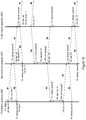
- Beacon apparatus 200 will attempt to broadcast its version of the call list to the other members of the beacon group via its radio-frequency transceiver.
- This initial message is illustrated with an exemplary type field value of "M1". It may be advantageous to detect, later on, whether subsequent messages belong to a distribution flow set up by this particular beacon apparatus 200. While this detection may be performed on the basis of a message identifier, it is also possible to include an identifier of the initiating beacon apparatus in the M1 message and the subsequent messages. This element is shown as the "Initiator" field in the figures.
- beacon apparatus 200 will reach neighboring beacon apparatus 201 , 204 (these beacon apparatus are referred to as the "second beacon apparatus" in the description of claimed method).
- neighboring beacon apparatus 201 , 204 receives the broadcast, it will verify whether the broadcast pertains to its beacon group and, if so, it will relay the message with the call list via its own radio-frequency transceiver to the next neighbors in range 202 , 203.
- beacon apparatus may be configured to relay call list messages regardless of whether they are from a beacon apparatus in the same beacon group, to improve the chances of actually reaching all members of the beacon group; in that case, it is preferred to limit the total number of permitted relay hops (e.g., by including a "time-to-live” field in the message, which gets decremented on every relay hop), to avoid flooding the entire facility's network with messages.
- the relayed messages are illustrated with an exemplary type field value of "M2".
- a beacon apparatus that processes the call list may update the call list by adding locally stored call list information, insofar as it is able to ascertain that its locally stored information is up to date (for instance, on the basis of optional timestamps included with the call and clearance events stored in the relayed call list), so as to ensure that the most complete and up-to-date version of the call list is relayed.
- each beacon apparatus that passes on the message preferably keeps track of the messages it has already relayed - all call list messages preferably carry a unique identification number for this purpose (shown as the "Id" field in Figures 4a-4c ).
- the call list messages preferably carry a "Seen by" field, which is updated upon every relaying step.
- the "Seen by" field may take the form of a bit map, in which each member of the beacon group has a pre-assigned bit position, which it sets when it processes the message (shown as the "Seen by" field in Figures 4a-4c ).
- beacon apparatus Whenever one of the beacons of the beacon group transmits a call list message via its radio-frequency transceiver, it will be able to detect via that same radio-frequency transceiver whether any neighboring beacon apparatus passes the message on. If the beacon apparatus that initiates the distribution detects that its message is not being relayed, it may conclude that it is isolated, and may switch to fully local operation, which may include emitting visual and auditory signals to attract attention from personnel.
- a downstream beacon apparatus i.e ., a "third beacon apparatus”
- a third beacon apparatus detects that its message is not being relayed, it may conclude that it is the last node of a sector of the network. In the illustrated example, this is the case for beacon apparatus 202 , 203 , and 204. In that case, the beacon apparatus starts a reverse ripple communication, with a view to distributing the "Seen by" information back to the originating beacon. This reverse ripple is illustrated in Figure 4b .
- the end point messages of the reverse ripple contain a reference to the unique identification of the original call list message (shown as the "Id" field in Figure 4b , which is identical to that of Figure 4a ), and a message type indication that distinguishes it from the latter (shown in Figure 4b as a type field with an exemplary value of "M3", which is different from that of Figure 4a ).
- the updated call list should also be included in the upstream ripple messages (not illustrated) .
- the reverse ripple consists of the original end point messages, and corresponding M3 messages relayed by the beacon apparatus upstream from the end points (these beacon apparatus are referred to as the "fourth beacon apparatus"). In the illustrated example, this is the case for beacon apparatus 201 and 204. Optionally, there may be further relaying steps by beacon apparatus that received the aforementioned corresponding M3 messages (these beacon apparatus are referred to as the "fifth beacon apparatus").
- the beacon apparatus may merge these messages (for instance by applying an OR operation to the respective bitmaps), and relay the result.
- this is the case for beacon apparatus 201 , which receives reports from beacon apparatus 202 and 203.
- the updated call lists may be merged in the same way (not illustrated).
- a third ripple is started to distribute the combined "Seen by" field, and optionally, the updated call list, to all members of the beacon group.
- This third ripple is illustrated in Figure 4c .
- the third ripple message contains a reference to the unique identification of the original call list message (shown as the "Id" field in Figure 4c , which is identical to that of Figures 4a and 4b ), and a message type indication that distinguishes it from the latter (shown in Figure 4c as a type field value of "M4", which is different from that of Figures 4a and 4b ).
- beacon apparatus Only after this third ripple has taken place, all beacon apparatus will be able to (1) present an up-to-date call list to any member of personnel checking in at that beacon apparatus, and (2) confirm that the list is indeed complete, by indicating that all beacon group members have processed the call list message. If any beacon group member is missing from the "seen-by" list, the checked beacon will also be able to give an indication of that fact, which will allow personnel to treat the missing beacon apparatus as isolated.
- a call list update distribution is triggered by the occurrence of a new call 510.
- the beacon apparatus at which the call is set initiates the downstream ripple by broadcasting 520 a call list update message of the first type (M1). Upon sending this message, it sets a time-out T1, sets flag F1, and listens for relaying of its message by neighboring beacon apparatus. If no relaying is detected by the expiry of T1, the originating beacon apparatus decides that it is isolated.
- a regime change 610 takes place, for instance a timed regime change which occurs without human intervention.
- a pre-designated member of the beacon group initiates 620 the distribution of the then-current call list.
- the distribution happens through the ripple message protocol 630 described above, with a message such as or similar to the M1 message described above, using a "Seen by" field whose size reflects the new composition of the beacon group, whereby it may again be useful to allow downstream beacon apparatus to modify the call list under relay, to facilitate the merging of call lists of previously separate beacon groups.
- Figure 7 schematically illustrates the processing carried out by an exemplary beacon apparatus according to an embodiment of the present invention, upon receipt 710 of a call list distribution message.
- the processing depends on the received message type.
- the selection of the appropriate processing is schematically illustrated as a cascade of type field evaluations 720 , 730 , 740 , 750 , but the skilled person will understand that this evaluation does not have to be implemented in a sequential manner.
- the receiving beacon apparatus will preferably assess 733 whether the message pertains to the same beacon group as the one it belongs to. If this is the case, it updates 734 the "Seen by" field, which may take the form of a bitmap as explained above. The receiving beacon apparatus then proceeds by retransmitting 735 the call list information, with the optionally updated "Seen by" field; this new message is now designated as an "M2" message. It also starts 736 a timer T1 (see also Figure 8 ).
- the receiving beacon apparatus will assess 731 , preferably on the basis of a unique identifier of the message or the specific distribution flow, whether the message has been received before. If this is the case, the receiving beacon apparatus stops 732 any timer T1 that may be running with respect to that message (see below) and clears flag F1 (indicating that the beacon apparatus is not isolated). If it is not the case, the receiving beacon apparatus will preferably assess 733 whether the message pertains to the same beacon group as the one it belongs to, and proceed as described above for messages of the "M1" type.
- the receiving beacon apparatus will assess 741 , preferably on the basis of a unique identifier of the message or the specific distribution flow, whether the message has been received before. If this is the case, no further action is necessary. If this is not the case, the receiving beacon apparatus starts or restarts 742 a timer T2.
- the received "M3" message is buffered 743 , and its "Seen by" field is merged (e.g., by OR' ing bitmaps) 744 with the corresponding fields of other "M3" messages that may be received during the time allowed by timer T2 (see also Figure 9 ).
- the receiving beacon apparatus will assess 751 , preferably on the basis of a unique identifier of the message or the specific distribution flow, whether the message has been received before. If this is the case, the receiving beacon apparatus evaluates 752 the call list, and thenceforth uses this call list to display the relevant information to personnel that checks in at that beacon apparatus. If it is not the case, the "M4" message is retransmitted to further its distribution to the other members of the beacon group.
- timer T1 allows any beacon apparatus that has transmitted an M2 message to determine whether it is the last beacon apparatus in a given sector of the network.
- the timer will only be allowed to expire (without being stopped at step 732 described above), if no copies of the transmitted M2 message are received back from any neighboring beacon apparatus.
- the transmitting beacon Upon expiry 810 of the timer, the transmitting beacon checks 820 whether it is the originating beacon apparatus, as indicated by flag F1 (see Figure 5 ). If this is the case, it activates local mode 830.
- the beacon apparatus should start an upstream ripple by transmitting 840 an M3 message, which includes the most up-to-date version of the "seen by" field for that sector.
- the initial M3 message sent out by the beacon apparatus at the end of a sector is also referred to as an "end point message”.
- timer T2 allows any beacon that has received an M3 message to wait for additional M3 messages before forwarding the (merged) "seen by" information along the upstream ripple.
- the receiving beacon can merge 920 the "seen by" fields of the various received M3 messages (of course, if no further M3 messages are received, no merging has to take place).
- the beacon apparatus also checks 930 whether it is the beacon that initiated this particular call list distribution flow. If that is the case, the upstream ripple has come to an end, and the beacon apparatus starts the third ripple by broadcasting 940 an M4 message. If it is not the case, the upstream ripple has to continue, and the beacon apparatus relays 950 the updated "seen by" information under the form of an M3 message.
- Figure 10 summarizes the previous figures in a single message diagram.
- the indicated reference numbers refer to the same steps as those appearing in preceding figures, but steps that are not strictly necessary to illustrate the general flow of the protocol have been omitted or simplified for clarity purposes.
- the distribution of nurse call information is assumed to start from a first beacon apparatus 200 , and further interactions are limited to a second beacon apparatus 201 and a third beacon apparatus 202.
- the interaction is assumed to be triggered by the receipt of a new call 510 at the first beacon apparatus 200.
- Upon receiving that trigger it broadcasts 520 an M1 message and starts 530 timer T1.
- Timer T1 allows the beacon to detect whether the message it transmits is being redistributed by subsequent beacon apparatus.
- the M1 message is received by second beacon apparatus 201 , which checks 731 if this particular M1 message (or an M2 counterpart) has been received before, finding that it hasn't. It then broadcasts 735 a corresponding M2 message and starts 736 timer T1.
- the receipt of this corresponding M2 message by the first beacon apparatus 200 causes the latter to check 731 if this M2 message has been received before and, finding that it is the counterpart of its own M1 message, to stop timer T1.
- the receipt of the M2 message by the third beacon apparatus 202 causes the latter to check 731 if this M2 message has been received before and, finding that it hasn't, broadcast 735 a corresponding M2 message and start 736 its timer T1.
- the timer T1 of further beacon apparatus 202 will expire before any further echoes of its M2 message are received.
- the expiry of timer T1 of the third beacon apparatus 202 starts the upstream part of the message flow.
- the third beacon apparatus 202 broadcasts 840 an M3 end point message.
- the receipt of the M3 end point message by the second beacon apparatus 201 causes the latter to check 741 if this M3 message has been received before and, finding that it hasn't, start 742 its timer T2, allowing it to gather further incoming M3 messages (if any) and combine them, before sending out the combined information.
- the type of the next broadcast depends 930 on whether the received M3 message(s) corresponded to an M1 message sent at the initiative of the second beacon apparatus 201.
- the second beacon apparatus 201 broadcasts 950 a (combined) M3 message.
- the receipt of that M3 message by the first beacon apparatus 200 causes the latter to check 741 if this M3 message has been received before and, finding that it hasn't, start 742 its timer T2, allowing it to gather further incoming M3 messages (if any) and combine them, before sending out the combined information.
- the type of the next broadcast again depends 930 on whether the received M3 message(s) corresponded to an M1 message sent at the initiative of the first beacon apparatus 200. Finding that this is the case, the first beacon apparatus 200 broadcasts 940 a (combined) M4 message.
- the broadcasting of the M4 message by the first beacon apparatus 200 starts the second downstream part of the message flow.
- the M4 message is received by second beacon apparatus 201B , which checks 751 if this particular M4 message has been received before, finding that it hasn't. It then broadcasts 753 a corresponding M4 message.
- the corresponding M4 message is received by further beacon apparatus 202 , which checks 751 if this particular M4 message has been received before, finding that it hasn't. It then again broadcasts 753 a corresponding M4 message. While the first beacon apparatus 200 and the second beacon apparatus 201 also receive the M4 messages sent by their downstream neighbors, they don't act on it, as the check 751 will reveal that they are effectively duplicates.
- the protocol can optionally be simplified in some respects.
- the information merging function ('OR' function) described above with respect to M3 messages could already be applied to the M2 messages, because many or all of the M2 messages will be received by the initiating beacon, which can therefore easily determine which other beacon apparatus have processed the original M1 message.
- the M3 messages may be skipped for this reason. For the same reason, it is not necessary to relay a message received at a beacon apparatus via a wired interface further via the same wired interface.
Landscapes
- Engineering & Computer Science (AREA)
- General Business, Economics & Management (AREA)
- Health & Medical Sciences (AREA)
- Business, Economics & Management (AREA)
- Biomedical Technology (AREA)
- Signal Processing (AREA)
- Computer Networks & Wireless Communication (AREA)
- Epidemiology (AREA)
- General Health & Medical Sciences (AREA)
- Medical Informatics (AREA)
- Primary Health Care (AREA)
- Public Health (AREA)
- Mobile Radio Communication Systems (AREA)
Claims (11)
- System, das eine Vielzahl von Bakenvorrichtungen (200, 201, 202), die angepasst sind, Krankenschwesternrufe zu registrieren, und einen Server (300) umfasst, wobei die Vielzahl von Bakenvorrichtungen (200, 201, 202) mittels eines Netzwerks mit dem Server (300) verbindbar sind; wobei eine erste Bakenvorrichtung der Vielzahl von Bakenvorrichtungen zu Folgendem ausgelegt ist:- Detektieren, ob sie mit dem Server (300) wirkverbunden ist;- wenn die erste Bakenvorrichtung mit dem Server (300) wirkverbunden ist, Verteilen von Informationen, die zu den Krankenschwesternrufen gehören, via das Netzwerk an den Server (300) und- andernfalls Verteilen von Informationen, die zu den Krankenschwesternrufen gehören, als eine erste Nachricht (M1) an mindestens eine Zielbake aus der Vielzahl von Baken, die via das Netzwerk erreichbar ist;wobei die Informationen, die zu den Krankenschwesternrufen gehören, Informationen, die zu einer Ruflistenänderung gehören, die an der ersten Bakenvorrichtung detektiert wurde, oder Informationen, die zu ausstehenden Rufen gehören, die an der ersten Bakenvorrichtung und/oder an anderen Bakenvorrichtungen der Vielzahl von Bakenvorrichtungen empfangen wurden, umfassen;
wobei die erste Bakenvorrichtung einer Bakengruppe zugewiesen ist und wobei die erste Bakenvorrichtung ferner dazu ausgelegt ist, alle Baken, die via das Netzwerk erreichbar sind und die der Bakengruppe zugewiesen sind, als die mindestens eine Zielbake auszuwählen;
wobei eine oder mehrere zweite Bakenvorrichtungen (201, 204) der Vielzahl von Bakenvorrichtungen angepasst sind, jeweilige entsprechende zweite Nachrichten (M2) zu verteilen (735), nachdem sie die erste Nachricht (M1) empfangen haben;
wobei eine Anzahl von dritten Bakenvorrichtungen (202, 203) der Vielzahl von Bakenvorrichtungen angepasst sind, jeweilige entsprechende zweite Nachrichten (M2) zu verteilen (735), nachdem sie zweite Nachrichten (M2) empfangen haben;
wobei jede der zweiten Bakenvorrichtungen (201, 204) und der dritten Bakenvorrichtungen (202, 203) ferner angepasst ist zu detektieren (731; 736), ob die jeweilige zweite Nachricht (M2) von anderen Baken der Vielzahl von Baken neu verteilt wird; und, wenn dies nicht der Fall ist, jeweilige Endpunktnachrichten (M3), die eine Anzeige umfassen, welche Bakenvorrichtungen die jeweilige zweite Nachricht (M2) verteilt haben, zu verteilen (840);
wobei eine oder mehrere vierte Bakenvorrichtungen (201, 204) der Vielzahl von Bakenvorrichtungen angepasst sind, jeweilige entsprechende dritte Nachrichten (M3) zu verteilen (950), nachdem sie die Endpunktnachrichten (M3) empfangen haben; und
wobei eine Anzahl von fünften Bakenvorrichtungen der Vielzahl von Bakenvorrichtungen angepasst sind, jeweilige entsprechende dritte Nachrichten (M3) zu verteilen (950), nachdem sie dritte Nachrichten (M3) empfangen haben. - System nach Anspruch 1,
wobei die erste Bakenvorrichtung (200) ferner angepasst ist, eine vierte Originalnachricht (M4) zu verteilen (940) ;
wobei die eine oder die mehreren zweiten Bakenvorrichtungen (201, 204) ferner angepasst sind, jeweilige entsprechende vierte Nachrichten (M4) zu verteilen (753), nachdem sie die vierte Originalnachricht (M4) empfangen haben, und wobei die Anzahl dritter Bakenvorrichtungen (202, 203) ferner angepasst sind, jeweilige entsprechende vierte Nachrichten (M4) zu verteilen (753), nachdem sie entsprechende vierte Nachrichten (M4) empfangen haben. - System nach Anspruch 1 oder Anspruch 2, wobei mindestens zwei der Vielzahl von Bakenvorrichtungen (200, 201, 202) jeweilige Funkfrequenzsendeempfänger zum Empfangen von Identifikationsnachrichten von einem Identifikationstag umfassen und wobei das Netzwerk einen drahtlosen Link umfasst, der von den jeweiligen Funkfrequenzsendeempfängern bereitgestellt wird.
- System nach einem der Ansprüche 1-3, wobei die Vielzahl von Bakenvorrichtungen (200, 201, 202) jeweilige Funkfrequenzsendeempfänger zum Empfangen von Identifikationsnachrichten von einem Identifikationstag umfassen und wobei das Netzwerk aus drahtlosen Links besteht, die von den jeweiligen Funkfrequenzsendeempfängern bereitgestellt werden.
- System nach einem der vorhergehenden Ansprüche, wobei die Ruflistenänderung ein neu detektierter Ruf ist.
- System nach einem der vorhergehenden Ansprüche, wobei die Ruflistenänderung eine Stornierung eines Rufs ist.
- System nach einem der vorhergehenden Ansprüche, wobei das Verteilen von Informationen von einer geplanten Änderung an Bakengruppenzuweisungen ausgelöst wird.
- Verfahren zum Verteilen von Informationen, die zu Krankenschwesternrufen gehören, in einem System, das eine Vielzahl von Bakenvorrichtungen (200-204), die angepasst sind, Krankenschwesternrufe zu registrieren, und einen Server (300) umfasst, wobei die Vielzahl von Bakenvorrichtungen (200-204) mittels eines Netzwerks mit dem Server (300) verbindbar sind;
wobei das Verfahren, wenn ein Fehlen einer Wirkverbindung zwischen einer ersten Bake (200) der Vielzahl von Bakenvorrichtungen und dem Server (300) detektiert wird, das Folgendes umfasst:- Verteilen (520) von Informationen, die zu den Krankenschwesternrufen gehören, als eine erste Nachricht (M1) von der ersten Bakenvorrichtung (200), wobei die Informationen, die zu den Krankenschwesternrufen gehören, Informationen, die zu einer Ruflistenänderung gehören, die an der ersten Bakenvorrichtung detektiert wurde, oder Informationen, die zu ausstehenden Rufen gehören, die an der ersten Bakenvorrichtung und/oder an anderen Bakenvorrichtungen der Vielzahl von Bakenvorrichtungen empfangen wurden, umfassen;- Verteilen (735) von jeweiligen entsprechenden zweiten Nachrichten (M2) von einer oder mehreren zweiten Bakenvorrichtungen (201, 204) der Vielzahl von Bakenvorrichtungen, wobei die zweiten Bakenvorrichtungen die erste Nachricht (M1) empfangen haben, und von einer Anzahl von dritten Bakenvorrichtungen (202, 203) der Vielzahl von Bakenvorrichtungen, wobei die dritten Bakenvorrichtungen (202, 203) zweite Nachrichten (M2) empfangen haben;- Detektieren (731; 736) an jeder der zweiten Bakenvorrichtungen (201, 204) und der dritten Bakenvorrichtungen (202, 203), ob die jeweilige zweite Nachricht (M2) von anderen Baken der Vielzahl von Baken neu verteilt wird; und, wenn dies nicht der Fall ist, Verteilen (840) jeweiliger Endpunktnachrichten (M3), die eine Anzeige umfassen, welche Bakenvorrichtungen die jeweilige zweite Nachricht (M2) verteilt haben; und- Verteilen (950) von jeweiligen entsprechenden dritten Nachrichten (M3) von einer oder mehreren vierten Bakenvorrichtungen (201, 204) der Vielzahl von Bakenvorrichtungen, wobei die vierten Bakenvorrichtungen die Endpunktnachrichten (M3) empfangen haben, und von einer Anzahl von fünften Bakenvorrichtungen, wobei die fünften Bakenvorrichtungen dritte Nachrichten (M3) empfangen haben. - Verfahren nach Anspruch 8, wobei das Verteilen (950) der jeweiligen entsprechenden dritten Nachrichten (M3) ferner Folgendes umfasst: Kombinieren der Anzeige einer Vielzahl von empfangenen Endpunktnachrichten (M3) und/oder entsprechenden dritten Nachrichten (M3) in den entsprechenden dritten Nachrichten (M3), die zu verteilen sind.
- Verfahren nach Anspruch 8 oder Anspruch 9, das ferner Folgendes umfasst:- Verteilen (940) einer vierten Originalnachricht (M4) von der ersten Bakenvorrichtung (200) und- Verteilen (753) von jeweiligen entsprechenden vierten Nachrichten (M4) von der einen oder den mehreren zweiten Bakenvorrichtungen (201, 204), wobei die zweiten Bakenvorrichtungen die vierte Originalnachricht (M4) empfangen haben, und von der Anzahl von dritten Bakenvorrichtungen (202, 203), wobei die dritten Bakenvorrichtungen (202, 203) entsprechende vierte Nachrichten (M4) empfangen haben.
- Bakenvorrichtung, die beim Verfahren nach einem der Ansprüche 8-10 zum Verwenden als die erste Bakenvorrichtung, die zweite Bakenvorrichtung, die dritte Bakenvorrichtung, die vierte Bakenvorrichtung und die fünfte Bakenvorrichtung angepasst ist.
Priority Applications (2)
| Application Number | Priority Date | Filing Date | Title |
|---|---|---|---|
| EP14178642.6A EP2976992B1 (de) | 2014-07-25 | 2014-07-25 | Pflegerufsystem mit lokalem betriebsmodus |
| EP15178547.4A EP2976996B1 (de) | 2014-07-25 | 2015-07-27 | Pflegerufsystem mit lokalem betriebsmodus |
Applications Claiming Priority (1)
| Application Number | Priority Date | Filing Date | Title |
|---|---|---|---|
| EP14178642.6A EP2976992B1 (de) | 2014-07-25 | 2014-07-25 | Pflegerufsystem mit lokalem betriebsmodus |
Publications (2)
| Publication Number | Publication Date |
|---|---|
| EP2976992A1 EP2976992A1 (de) | 2016-01-27 |
| EP2976992B1 true EP2976992B1 (de) | 2019-12-18 |
Family
ID=51225354
Family Applications (2)
| Application Number | Title | Priority Date | Filing Date |
|---|---|---|---|
| EP14178642.6A Active EP2976992B1 (de) | 2014-07-25 | 2014-07-25 | Pflegerufsystem mit lokalem betriebsmodus |
| EP15178547.4A Active EP2976996B1 (de) | 2014-07-25 | 2015-07-27 | Pflegerufsystem mit lokalem betriebsmodus |
Family Applications After (1)
| Application Number | Title | Priority Date | Filing Date |
|---|---|---|---|
| EP15178547.4A Active EP2976996B1 (de) | 2014-07-25 | 2015-07-27 | Pflegerufsystem mit lokalem betriebsmodus |
Country Status (1)
| Country | Link |
|---|---|
| EP (2) | EP2976992B1 (de) |
Family Cites Families (6)
| Publication number | Priority date | Publication date | Assignee | Title |
|---|---|---|---|---|
| DE10242534A1 (de) * | 2002-09-12 | 2004-03-25 | Siemens Ag | Rufanlage auf Basis einer digitalen Telekommunikationsanlage |
| US7359339B2 (en) * | 2003-12-23 | 2008-04-15 | Lenovo Singapore Pte Ltd | Smart access point |
| US7912003B2 (en) * | 2007-06-27 | 2011-03-22 | Microsoft Corporation | Multipath forwarding algorithms using network coding |
| US8384526B2 (en) * | 2008-02-22 | 2013-02-26 | Hill-Rom Services, Inc. | Indicator apparatus for healthcare communication system |
| HU227600B1 (hu) * | 2009-06-23 | 2011-09-28 | Attila Angyal | Eljárás vezeték nélküli fix egységek által meghatározott zónákban mozgó mobil egységek nyomvonal követésére és nyilvántartására |
| KR20120100473A (ko) * | 2011-03-04 | 2012-09-12 | 삼성전자주식회사 | 통신시스템에서 기지국의 중계 모드를 제어하기 위한 장치 및 방법 |
-
2014
- 2014-07-25 EP EP14178642.6A patent/EP2976992B1/de active Active
-
2015
- 2015-07-27 EP EP15178547.4A patent/EP2976996B1/de active Active
Non-Patent Citations (1)
| Title |
|---|
| None * |
Also Published As
| Publication number | Publication date |
|---|---|
| EP2976992A1 (de) | 2016-01-27 |
| EP2976996B1 (de) | 2019-05-29 |
| EP2976996A1 (de) | 2016-01-27 |
Similar Documents
| Publication | Publication Date | Title |
|---|---|---|
| US10660019B2 (en) | Locating physical assets via near field communication nodes | |
| US10588173B2 (en) | Wi-Fi mesh fire detection system | |
| CN101682542B (zh) | 挂起无线网络中的传输 | |
| US20200037252A1 (en) | Master Slave Wireless Fire Alarm And Mass Notification System | |
| US6934298B2 (en) | Hot standby access point | |
| CN1849779B (zh) | 用于在微微网通信系统内发现邻者的方法和设备 | |
| EP2987358A1 (de) | Schnittstellenlose funktion in einer drahtlosen maschennetzwerkvorrichtung | |
| US20070066334A1 (en) | Locating system utilising adjustable transmission power in a micro-cellular network | |
| US20130176859A1 (en) | Wireless control plane failure handling in a split-plane deployment | |
| CN105282770A (zh) | 无线自愈式组网优化与自检方法 | |
| JP2002369255A (ja) | 無線通信方法、無線通信システム、並びに無線伝送装置 | |
| EP2976992B1 (de) | Pflegerufsystem mit lokalem betriebsmodus | |
| CN207135281U (zh) | 一种生产实时信息管理系统 | |
| EP2978164B1 (de) | Hybrides Pflegerufsystem | |
| CN107302481B (zh) | 一种1553b总线网络及串行总线网络的跨网状态可靠切换方法 | |
| JP2008228046A (ja) | 無線ネットワークの故障診断システムおよび故障診断方法 | |
| US20200187020A1 (en) | In-facility transmission system, in-facility transmission method, and base station | |
| IL193755A (en) | A method for identifying hidden nodes in an ad hoc network | |
| JP6957142B2 (ja) | 制御装置、無線通信装置及びチャネル制御方法 | |
| CN115134951A (zh) | 一种对等模式的无线组网通信方法 | |
| JP2005354625A (ja) | マルチホップデータ転送経路構築方法、ネットワークシステム | |
| CN115696179A (zh) | 定位系统和方法 | |
| WO2013086821A1 (zh) | 一种组网物理连接状况的自动检测的方法和系统 | |
| JP2007251712A (ja) | 無線通信システム、及びデータ収集方法 | |
| AU2004303130A1 (en) | Locating system utilising adjustable transmission power in a micro-cellular network |
Legal Events
| Date | Code | Title | Description |
|---|---|---|---|
| PUAI | Public reference made under article 153(3) epc to a published international application that has entered the european phase |
Free format text: ORIGINAL CODE: 0009012 |
|
| AK | Designated contracting states |
Kind code of ref document: A1 Designated state(s): AL AT BE BG CH CY CZ DE DK EE ES FI FR GB GR HR HU IE IS IT LI LT LU LV MC MK MT NL NO PL PT RO RS SE SI SK SM TR |
|
| AX | Request for extension of the european patent |
Extension state: BA ME |
|
| 17P | Request for examination filed |
Effective date: 20160719 |
|
| RBV | Designated contracting states (corrected) |
Designated state(s): AL AT BE BG CH CY CZ DE DK EE ES FI FR GB GR HR HU IE IS IT LI LT LU LV MC MK MT NL NO PL PT RO RS SE SI SK SM TR |
|
| STAA | Information on the status of an ep patent application or granted ep patent |
Free format text: STATUS: EXAMINATION IS IN PROGRESS |
|
| 17Q | First examination report despatched |
Effective date: 20181214 |
|
| REG | Reference to a national code |
Ref country code: DE Ref legal event code: R079 Ref document number: 602014058485 Country of ref document: DE Free format text: PREVIOUS MAIN CLASS: A61B0005000000 Ipc: G16H0040200000 |
|
| GRAP | Despatch of communication of intention to grant a patent |
Free format text: ORIGINAL CODE: EPIDOSNIGR1 |
|
| STAA | Information on the status of an ep patent application or granted ep patent |
Free format text: STATUS: GRANT OF PATENT IS INTENDED |
|
| RIC1 | Information provided on ipc code assigned before grant |
Ipc: A61B 5/00 20060101ALN20190621BHEP Ipc: G16H 40/20 20180101AFI20190621BHEP Ipc: H04W 88/04 20090101ALN20190621BHEP Ipc: H04W 68/00 20090101ALI20190621BHEP |
|
| INTG | Intention to grant announced |
Effective date: 20190718 |
|
| GRAS | Grant fee paid |
Free format text: ORIGINAL CODE: EPIDOSNIGR3 |
|
| GRAA | (expected) grant |
Free format text: ORIGINAL CODE: 0009210 |
|
| STAA | Information on the status of an ep patent application or granted ep patent |
Free format text: STATUS: THE PATENT HAS BEEN GRANTED |
|
| AK | Designated contracting states |
Kind code of ref document: B1 Designated state(s): AL AT BE BG CH CY CZ DE DK EE ES FI FR GB GR HR HU IE IS IT LI LT LU LV MC MK MT NL NO PL PT RO RS SE SI SK SM TR |
|
| REG | Reference to a national code |
Ref country code: CH Ref legal event code: EP |
|
| REG | Reference to a national code |
Ref country code: DE Ref legal event code: R096 Ref document number: 602014058485 Country of ref document: DE |
|
| REG | Reference to a national code |
Ref country code: IE Ref legal event code: FG4D |
|
| REG | Reference to a national code |
Ref country code: AT Ref legal event code: REF Ref document number: 1215483 Country of ref document: AT Kind code of ref document: T Effective date: 20200115 |
|
| REG | Reference to a national code |
Ref country code: NL Ref legal event code: MP Effective date: 20191218 |
|
| PG25 | Lapsed in a contracting state [announced via postgrant information from national office to epo] |
Ref country code: SE Free format text: LAPSE BECAUSE OF FAILURE TO SUBMIT A TRANSLATION OF THE DESCRIPTION OR TO PAY THE FEE WITHIN THE PRESCRIBED TIME-LIMIT Effective date: 20191218 Ref country code: LV Free format text: LAPSE BECAUSE OF FAILURE TO SUBMIT A TRANSLATION OF THE DESCRIPTION OR TO PAY THE FEE WITHIN THE PRESCRIBED TIME-LIMIT Effective date: 20191218 Ref country code: NO Free format text: LAPSE BECAUSE OF FAILURE TO SUBMIT A TRANSLATION OF THE DESCRIPTION OR TO PAY THE FEE WITHIN THE PRESCRIBED TIME-LIMIT Effective date: 20200318 Ref country code: GR Free format text: LAPSE BECAUSE OF FAILURE TO SUBMIT A TRANSLATION OF THE DESCRIPTION OR TO PAY THE FEE WITHIN THE PRESCRIBED TIME-LIMIT Effective date: 20200319 Ref country code: FI Free format text: LAPSE BECAUSE OF FAILURE TO SUBMIT A TRANSLATION OF THE DESCRIPTION OR TO PAY THE FEE WITHIN THE PRESCRIBED TIME-LIMIT Effective date: 20191218 Ref country code: LT Free format text: LAPSE BECAUSE OF FAILURE TO SUBMIT A TRANSLATION OF THE DESCRIPTION OR TO PAY THE FEE WITHIN THE PRESCRIBED TIME-LIMIT Effective date: 20191218 Ref country code: BG Free format text: LAPSE BECAUSE OF FAILURE TO SUBMIT A TRANSLATION OF THE DESCRIPTION OR TO PAY THE FEE WITHIN THE PRESCRIBED TIME-LIMIT Effective date: 20200318 |
|
| REG | Reference to a national code |
Ref country code: LT Ref legal event code: MG4D |
|
| PG25 | Lapsed in a contracting state [announced via postgrant information from national office to epo] |
Ref country code: HR Free format text: LAPSE BECAUSE OF FAILURE TO SUBMIT A TRANSLATION OF THE DESCRIPTION OR TO PAY THE FEE WITHIN THE PRESCRIBED TIME-LIMIT Effective date: 20191218 Ref country code: RS Free format text: LAPSE BECAUSE OF FAILURE TO SUBMIT A TRANSLATION OF THE DESCRIPTION OR TO PAY THE FEE WITHIN THE PRESCRIBED TIME-LIMIT Effective date: 20191218 |
|
| PG25 | Lapsed in a contracting state [announced via postgrant information from national office to epo] |
Ref country code: AL Free format text: LAPSE BECAUSE OF FAILURE TO SUBMIT A TRANSLATION OF THE DESCRIPTION OR TO PAY THE FEE WITHIN THE PRESCRIBED TIME-LIMIT Effective date: 20191218 |
|
| PG25 | Lapsed in a contracting state [announced via postgrant information from national office to epo] |
Ref country code: EE Free format text: LAPSE BECAUSE OF FAILURE TO SUBMIT A TRANSLATION OF THE DESCRIPTION OR TO PAY THE FEE WITHIN THE PRESCRIBED TIME-LIMIT Effective date: 20191218 Ref country code: RO Free format text: LAPSE BECAUSE OF FAILURE TO SUBMIT A TRANSLATION OF THE DESCRIPTION OR TO PAY THE FEE WITHIN THE PRESCRIBED TIME-LIMIT Effective date: 20191218 Ref country code: PT Free format text: LAPSE BECAUSE OF FAILURE TO SUBMIT A TRANSLATION OF THE DESCRIPTION OR TO PAY THE FEE WITHIN THE PRESCRIBED TIME-LIMIT Effective date: 20200513 Ref country code: NL Free format text: LAPSE BECAUSE OF FAILURE TO SUBMIT A TRANSLATION OF THE DESCRIPTION OR TO PAY THE FEE WITHIN THE PRESCRIBED TIME-LIMIT Effective date: 20191218 Ref country code: CZ Free format text: LAPSE BECAUSE OF FAILURE TO SUBMIT A TRANSLATION OF THE DESCRIPTION OR TO PAY THE FEE WITHIN THE PRESCRIBED TIME-LIMIT Effective date: 20191218 |
|
| PG25 | Lapsed in a contracting state [announced via postgrant information from national office to epo] |
Ref country code: SM Free format text: LAPSE BECAUSE OF FAILURE TO SUBMIT A TRANSLATION OF THE DESCRIPTION OR TO PAY THE FEE WITHIN THE PRESCRIBED TIME-LIMIT Effective date: 20191218 Ref country code: SK Free format text: LAPSE BECAUSE OF FAILURE TO SUBMIT A TRANSLATION OF THE DESCRIPTION OR TO PAY THE FEE WITHIN THE PRESCRIBED TIME-LIMIT Effective date: 20191218 Ref country code: IS Free format text: LAPSE BECAUSE OF FAILURE TO SUBMIT A TRANSLATION OF THE DESCRIPTION OR TO PAY THE FEE WITHIN THE PRESCRIBED TIME-LIMIT Effective date: 20200418 |
|
| REG | Reference to a national code |
Ref country code: DE Ref legal event code: R097 Ref document number: 602014058485 Country of ref document: DE |
|
| REG | Reference to a national code |
Ref country code: AT Ref legal event code: MK05 Ref document number: 1215483 Country of ref document: AT Kind code of ref document: T Effective date: 20191218 |
|
| PLBE | No opposition filed within time limit |
Free format text: ORIGINAL CODE: 0009261 |
|
| STAA | Information on the status of an ep patent application or granted ep patent |
Free format text: STATUS: NO OPPOSITION FILED WITHIN TIME LIMIT |
|
| PG25 | Lapsed in a contracting state [announced via postgrant information from national office to epo] |
Ref country code: DK Free format text: LAPSE BECAUSE OF FAILURE TO SUBMIT A TRANSLATION OF THE DESCRIPTION OR TO PAY THE FEE WITHIN THE PRESCRIBED TIME-LIMIT Effective date: 20191218 Ref country code: ES Free format text: LAPSE BECAUSE OF FAILURE TO SUBMIT A TRANSLATION OF THE DESCRIPTION OR TO PAY THE FEE WITHIN THE PRESCRIBED TIME-LIMIT Effective date: 20191218 |
|
| 26N | No opposition filed |
Effective date: 20200921 |
|
| PG25 | Lapsed in a contracting state [announced via postgrant information from national office to epo] |
Ref country code: SI Free format text: LAPSE BECAUSE OF FAILURE TO SUBMIT A TRANSLATION OF THE DESCRIPTION OR TO PAY THE FEE WITHIN THE PRESCRIBED TIME-LIMIT Effective date: 20191218 Ref country code: AT Free format text: LAPSE BECAUSE OF FAILURE TO SUBMIT A TRANSLATION OF THE DESCRIPTION OR TO PAY THE FEE WITHIN THE PRESCRIBED TIME-LIMIT Effective date: 20191218 |
|
| PG25 | Lapsed in a contracting state [announced via postgrant information from national office to epo] |
Ref country code: IT Free format text: LAPSE BECAUSE OF FAILURE TO SUBMIT A TRANSLATION OF THE DESCRIPTION OR TO PAY THE FEE WITHIN THE PRESCRIBED TIME-LIMIT Effective date: 20191218 |
|
| REG | Reference to a national code |
Ref country code: DE Ref legal event code: R119 Ref document number: 602014058485 Country of ref document: DE |
|
| PG25 | Lapsed in a contracting state [announced via postgrant information from national office to epo] |
Ref country code: MC Free format text: LAPSE BECAUSE OF FAILURE TO SUBMIT A TRANSLATION OF THE DESCRIPTION OR TO PAY THE FEE WITHIN THE PRESCRIBED TIME-LIMIT Effective date: 20191218 Ref country code: PL Free format text: LAPSE BECAUSE OF FAILURE TO SUBMIT A TRANSLATION OF THE DESCRIPTION OR TO PAY THE FEE WITHIN THE PRESCRIBED TIME-LIMIT Effective date: 20191218 |
|
| REG | Reference to a national code |
Ref country code: CH Ref legal event code: PL |
|
| GBPC | Gb: european patent ceased through non-payment of renewal fee |
Effective date: 20200725 |
|
| PG25 | Lapsed in a contracting state [announced via postgrant information from national office to epo] |
Ref country code: CH Free format text: LAPSE BECAUSE OF NON-PAYMENT OF DUE FEES Effective date: 20200731 Ref country code: LI Free format text: LAPSE BECAUSE OF NON-PAYMENT OF DUE FEES Effective date: 20200731 Ref country code: GB Free format text: LAPSE BECAUSE OF NON-PAYMENT OF DUE FEES Effective date: 20200725 Ref country code: LU Free format text: LAPSE BECAUSE OF NON-PAYMENT OF DUE FEES Effective date: 20200725 |
|
| PG25 | Lapsed in a contracting state [announced via postgrant information from national office to epo] |
Ref country code: DE Free format text: LAPSE BECAUSE OF NON-PAYMENT OF DUE FEES Effective date: 20210202 |
|
| PG25 | Lapsed in a contracting state [announced via postgrant information from national office to epo] |
Ref country code: IE Free format text: LAPSE BECAUSE OF NON-PAYMENT OF DUE FEES Effective date: 20200725 |
|
| PG25 | Lapsed in a contracting state [announced via postgrant information from national office to epo] |
Ref country code: TR Free format text: LAPSE BECAUSE OF FAILURE TO SUBMIT A TRANSLATION OF THE DESCRIPTION OR TO PAY THE FEE WITHIN THE PRESCRIBED TIME-LIMIT Effective date: 20191218 Ref country code: MT Free format text: LAPSE BECAUSE OF FAILURE TO SUBMIT A TRANSLATION OF THE DESCRIPTION OR TO PAY THE FEE WITHIN THE PRESCRIBED TIME-LIMIT Effective date: 20191218 Ref country code: CY Free format text: LAPSE BECAUSE OF FAILURE TO SUBMIT A TRANSLATION OF THE DESCRIPTION OR TO PAY THE FEE WITHIN THE PRESCRIBED TIME-LIMIT Effective date: 20191218 |
|
| PG25 | Lapsed in a contracting state [announced via postgrant information from national office to epo] |
Ref country code: MK Free format text: LAPSE BECAUSE OF FAILURE TO SUBMIT A TRANSLATION OF THE DESCRIPTION OR TO PAY THE FEE WITHIN THE PRESCRIBED TIME-LIMIT Effective date: 20191218 |
|
| P01 | Opt-out of the competence of the unified patent court (upc) registered |
Effective date: 20230602 |
|
| PGFP | Annual fee paid to national office [announced via postgrant information from national office to epo] |
Ref country code: FR Payment date: 20230726 Year of fee payment: 10 Ref country code: BE Payment date: 20230719 Year of fee payment: 10 |