EP2974754B1 - System zur verwaltung von reduziertem druck an einer gewebestelle - Google Patents
System zur verwaltung von reduziertem druck an einer gewebestelle Download PDFInfo
- Publication number
- EP2974754B1 EP2974754B1 EP15179753.7A EP15179753A EP2974754B1 EP 2974754 B1 EP2974754 B1 EP 2974754B1 EP 15179753 A EP15179753 A EP 15179753A EP 2974754 B1 EP2974754 B1 EP 2974754B1
- Authority
- EP
- European Patent Office
- Prior art keywords
- reduced pressure
- tissue site
- controller
- actual
- source
- Prior art date
- Legal status (The legal status is an assumption and is not a legal conclusion. Google has not performed a legal analysis and makes no representation as to the accuracy of the status listed.)
- Active
Links
- 230000004044 response Effects 0.000 claims description 20
- 230000004043 responsiveness Effects 0.000 claims description 9
- 230000008859 change Effects 0.000 claims description 8
- 230000003247 decreasing effect Effects 0.000 claims description 8
- 238000006243 chemical reaction Methods 0.000 claims description 5
- 238000012544 monitoring process Methods 0.000 claims description 5
- 210000001519 tissue Anatomy 0.000 description 152
- 238000000034 method Methods 0.000 description 78
- 230000008569 process Effects 0.000 description 73
- 238000007789 sealing Methods 0.000 description 29
- 239000012530 fluid Substances 0.000 description 22
- 230000007423 decrease Effects 0.000 description 17
- 239000000463 material Substances 0.000 description 14
- 230000006870 function Effects 0.000 description 13
- 206010052428 Wound Diseases 0.000 description 11
- 208000027418 Wounds and injury Diseases 0.000 description 11
- 210000000416 exudates and transudate Anatomy 0.000 description 11
- 238000007726 management method Methods 0.000 description 11
- 230000010261 cell growth Effects 0.000 description 5
- 239000007789 gas Substances 0.000 description 5
- 239000007788 liquid Substances 0.000 description 5
- 239000006260 foam Substances 0.000 description 4
- 230000012010 growth Effects 0.000 description 4
- 230000007246 mechanism Effects 0.000 description 4
- 229920000954 Polyglycolide Polymers 0.000 description 3
- 239000000853 adhesive Substances 0.000 description 3
- 230000001070 adhesive effect Effects 0.000 description 3
- 230000002950 deficient Effects 0.000 description 3
- 238000010586 diagram Methods 0.000 description 3
- 239000000203 mixture Substances 0.000 description 3
- 239000004633 polyglycolic acid Substances 0.000 description 3
- 230000009467 reduction Effects 0.000 description 3
- 206010063560 Excessive granulation tissue Diseases 0.000 description 2
- 238000001311 chemical methods and process Methods 0.000 description 2
- 238000001514 detection method Methods 0.000 description 2
- 230000000694 effects Effects 0.000 description 2
- 210000001126 granulation tissue Anatomy 0.000 description 2
- 230000035876 healing Effects 0.000 description 2
- 239000000017 hydrogel Substances 0.000 description 2
- 238000005259 measurement Methods 0.000 description 2
- 230000002093 peripheral effect Effects 0.000 description 2
- 239000004626 polylactic acid Substances 0.000 description 2
- 239000011148 porous material Substances 0.000 description 2
- 238000012545 processing Methods 0.000 description 2
- 239000007921 spray Substances 0.000 description 2
- 239000000126 substance Substances 0.000 description 2
- 238000002560 therapeutic procedure Methods 0.000 description 2
- 241000894006 Bacteria Species 0.000 description 1
- 235000014653 Carica parviflora Nutrition 0.000 description 1
- 241000243321 Cnidaria Species 0.000 description 1
- 102000008186 Collagen Human genes 0.000 description 1
- 108010035532 Collagen Proteins 0.000 description 1
- 206010016717 Fistula Diseases 0.000 description 1
- 241001465754 Metazoa Species 0.000 description 1
- 229920001247 Reticulated foam Polymers 0.000 description 1
- XUIMIQQOPSSXEZ-UHFFFAOYSA-N Silicon Chemical compound [Si] XUIMIQQOPSSXEZ-UHFFFAOYSA-N 0.000 description 1
- 238000010521 absorption reaction Methods 0.000 description 1
- NIXOWILDQLNWCW-UHFFFAOYSA-N acrylic acid group Chemical group C(C=C)(=O)O NIXOWILDQLNWCW-UHFFFAOYSA-N 0.000 description 1
- 239000013543 active substance Substances 0.000 description 1
- 210000000577 adipose tissue Anatomy 0.000 description 1
- 239000003570 air Substances 0.000 description 1
- 230000002547 anomalous effect Effects 0.000 description 1
- 239000003242 anti bacterial agent Substances 0.000 description 1
- 239000003443 antiviral agent Substances 0.000 description 1
- 239000011324 bead Substances 0.000 description 1
- 230000008901 benefit Effects 0.000 description 1
- 239000000560 biocompatible material Substances 0.000 description 1
- 230000005540 biological transmission Effects 0.000 description 1
- 229960000074 biopharmaceutical Drugs 0.000 description 1
- 229920001222 biopolymer Polymers 0.000 description 1
- 230000015572 biosynthetic process Effects 0.000 description 1
- 238000009530 blood pressure measurement Methods 0.000 description 1
- 210000000988 bone and bone Anatomy 0.000 description 1
- 229910000389 calcium phosphate Inorganic materials 0.000 description 1
- 239000001506 calcium phosphate Substances 0.000 description 1
- 235000011010 calcium phosphates Nutrition 0.000 description 1
- 239000003990 capacitor Substances 0.000 description 1
- 150000004649 carbonic acid derivatives Chemical class 0.000 description 1
- 210000000845 cartilage Anatomy 0.000 description 1
- 239000000919 ceramic Substances 0.000 description 1
- 239000003795 chemical substances by application Substances 0.000 description 1
- 229920001436 collagen Polymers 0.000 description 1
- 238000002485 combustion reaction Methods 0.000 description 1
- 238000004891 communication Methods 0.000 description 1
- 150000001875 compounds Chemical class 0.000 description 1
- 238000007906 compression Methods 0.000 description 1
- 230000006835 compression Effects 0.000 description 1
- 238000009833 condensation Methods 0.000 description 1
- 230000005494 condensation Effects 0.000 description 1
- 210000002808 connective tissue Anatomy 0.000 description 1
- 230000008878 coupling Effects 0.000 description 1
- 238000010168 coupling process Methods 0.000 description 1
- 238000005859 coupling reaction Methods 0.000 description 1
- 230000001419 dependent effect Effects 0.000 description 1
- 239000002274 desiccant Substances 0.000 description 1
- 230000002500 effect on skin Effects 0.000 description 1
- 230000008030 elimination Effects 0.000 description 1
- 238000003379 elimination reaction Methods 0.000 description 1
- 239000004744 fabric Substances 0.000 description 1
- 230000003890 fistula Effects 0.000 description 1
- 238000009472 formulation Methods 0.000 description 1
- 239000000499 gel Substances 0.000 description 1
- 238000010438 heat treatment Methods 0.000 description 1
- 230000002439 hemostatic effect Effects 0.000 description 1
- 230000002209 hydrophobic effect Effects 0.000 description 1
- 125000002887 hydroxy group Chemical group [H]O* 0.000 description 1
- 238000009434 installation Methods 0.000 description 1
- 230000002262 irrigation Effects 0.000 description 1
- 238000003973 irrigation Methods 0.000 description 1
- 210000003041 ligament Anatomy 0.000 description 1
- 238000012423 maintenance Methods 0.000 description 1
- 210000003205 muscle Anatomy 0.000 description 1
- -1 open-cell Polymers 0.000 description 1
- 230000003204 osmotic effect Effects 0.000 description 1
- 230000037361 pathway Effects 0.000 description 1
- 230000002572 peristaltic effect Effects 0.000 description 1
- 230000035699 permeability Effects 0.000 description 1
- 229920000747 poly(lactic acid) Polymers 0.000 description 1
- 229920000515 polycarbonate Polymers 0.000 description 1
- 239000004417 polycarbonate Substances 0.000 description 1
- 229920001296 polysiloxane Polymers 0.000 description 1
- 229920002635 polyurethane Polymers 0.000 description 1
- 239000004814 polyurethane Substances 0.000 description 1
- 230000036632 reaction speed Effects 0.000 description 1
- 239000000565 sealant Substances 0.000 description 1
- 229910052710 silicon Inorganic materials 0.000 description 1
- 239000010703 silicon Substances 0.000 description 1
- 239000007787 solid Substances 0.000 description 1
- 238000007920 subcutaneous administration Methods 0.000 description 1
- 210000002435 tendon Anatomy 0.000 description 1
- 239000004753 textile Substances 0.000 description 1
- QORWJWZARLRLPR-UHFFFAOYSA-H tricalcium bis(phosphate) Chemical compound [Ca+2].[Ca+2].[Ca+2].[O-]P([O-])([O-])=O.[O-]P([O-])([O-])=O QORWJWZARLRLPR-UHFFFAOYSA-H 0.000 description 1
- 230000002792 vascular Effects 0.000 description 1
- XLYOFNOQVPJJNP-UHFFFAOYSA-N water Substances O XLYOFNOQVPJJNP-UHFFFAOYSA-N 0.000 description 1
Images


Classifications
-
- A—HUMAN NECESSITIES
- A61—MEDICAL OR VETERINARY SCIENCE; HYGIENE
- A61M—DEVICES FOR INTRODUCING MEDIA INTO, OR ONTO, THE BODY; DEVICES FOR TRANSDUCING BODY MEDIA OR FOR TAKING MEDIA FROM THE BODY; DEVICES FOR PRODUCING OR ENDING SLEEP OR STUPOR
- A61M1/00—Suction or pumping devices for medical purposes; Devices for carrying-off, for treatment of, or for carrying-over, body-liquids; Drainage systems
- A61M1/71—Suction drainage systems
- A61M1/73—Suction drainage systems comprising sensors or indicators for physical values
- A61M1/732—Visual indicating means for vacuum pressure
-
- A—HUMAN NECESSITIES
- A61—MEDICAL OR VETERINARY SCIENCE; HYGIENE
- A61M—DEVICES FOR INTRODUCING MEDIA INTO, OR ONTO, THE BODY; DEVICES FOR TRANSDUCING BODY MEDIA OR FOR TAKING MEDIA FROM THE BODY; DEVICES FOR PRODUCING OR ENDING SLEEP OR STUPOR
- A61M1/00—Suction or pumping devices for medical purposes; Devices for carrying-off, for treatment of, or for carrying-over, body-liquids; Drainage systems
- A61M1/71—Suction drainage systems
- A61M1/74—Suction control
-
- A—HUMAN NECESSITIES
- A61—MEDICAL OR VETERINARY SCIENCE; HYGIENE
- A61M—DEVICES FOR INTRODUCING MEDIA INTO, OR ONTO, THE BODY; DEVICES FOR TRANSDUCING BODY MEDIA OR FOR TAKING MEDIA FROM THE BODY; DEVICES FOR PRODUCING OR ENDING SLEEP OR STUPOR
- A61M1/00—Suction or pumping devices for medical purposes; Devices for carrying-off, for treatment of, or for carrying-over, body-liquids; Drainage systems
- A61M1/90—Negative pressure wound therapy devices, i.e. devices for applying suction to a wound to promote healing, e.g. including a vacuum dressing
- A61M1/96—Suction control thereof
- A61M1/966—Suction control thereof having a pressure sensor on or near the dressing
-
- A—HUMAN NECESSITIES
- A61—MEDICAL OR VETERINARY SCIENCE; HYGIENE
- A61M—DEVICES FOR INTRODUCING MEDIA INTO, OR ONTO, THE BODY; DEVICES FOR TRANSDUCING BODY MEDIA OR FOR TAKING MEDIA FROM THE BODY; DEVICES FOR PRODUCING OR ENDING SLEEP OR STUPOR
- A61M1/00—Suction or pumping devices for medical purposes; Devices for carrying-off, for treatment of, or for carrying-over, body-liquids; Drainage systems
- A61M1/90—Negative pressure wound therapy devices, i.e. devices for applying suction to a wound to promote healing, e.g. including a vacuum dressing
- A61M1/91—Suction aspects of the dressing
- A61M1/912—Connectors between dressing and drainage tube
-
- A—HUMAN NECESSITIES
- A61—MEDICAL OR VETERINARY SCIENCE; HYGIENE
- A61M—DEVICES FOR INTRODUCING MEDIA INTO, OR ONTO, THE BODY; DEVICES FOR TRANSDUCING BODY MEDIA OR FOR TAKING MEDIA FROM THE BODY; DEVICES FOR PRODUCING OR ENDING SLEEP OR STUPOR
- A61M1/00—Suction or pumping devices for medical purposes; Devices for carrying-off, for treatment of, or for carrying-over, body-liquids; Drainage systems
- A61M1/90—Negative pressure wound therapy devices, i.e. devices for applying suction to a wound to promote healing, e.g. including a vacuum dressing
- A61M1/91—Suction aspects of the dressing
- A61M1/915—Constructional details of the pressure distribution manifold
-
- A—HUMAN NECESSITIES
- A61—MEDICAL OR VETERINARY SCIENCE; HYGIENE
- A61M—DEVICES FOR INTRODUCING MEDIA INTO, OR ONTO, THE BODY; DEVICES FOR TRANSDUCING BODY MEDIA OR FOR TAKING MEDIA FROM THE BODY; DEVICES FOR PRODUCING OR ENDING SLEEP OR STUPOR
- A61M1/00—Suction or pumping devices for medical purposes; Devices for carrying-off, for treatment of, or for carrying-over, body-liquids; Drainage systems
- A61M1/90—Negative pressure wound therapy devices, i.e. devices for applying suction to a wound to promote healing, e.g. including a vacuum dressing
- A61M1/98—Containers specifically adapted for negative pressure wound therapy
-
- A—HUMAN NECESSITIES
- A61—MEDICAL OR VETERINARY SCIENCE; HYGIENE
- A61M—DEVICES FOR INTRODUCING MEDIA INTO, OR ONTO, THE BODY; DEVICES FOR TRANSDUCING BODY MEDIA OR FOR TAKING MEDIA FROM THE BODY; DEVICES FOR PRODUCING OR ENDING SLEEP OR STUPOR
- A61M2205/00—General characteristics of the apparatus
- A61M2205/15—Detection of leaks
-
- A—HUMAN NECESSITIES
- A61—MEDICAL OR VETERINARY SCIENCE; HYGIENE
- A61M—DEVICES FOR INTRODUCING MEDIA INTO, OR ONTO, THE BODY; DEVICES FOR TRANSDUCING BODY MEDIA OR FOR TAKING MEDIA FROM THE BODY; DEVICES FOR PRODUCING OR ENDING SLEEP OR STUPOR
- A61M2205/00—General characteristics of the apparatus
- A61M2205/33—Controlling, regulating or measuring
- A61M2205/3331—Pressure; Flow
- A61M2205/3337—Controlling, regulating pressure or flow by means of a valve by-passing a pump
-
- A—HUMAN NECESSITIES
- A61—MEDICAL OR VETERINARY SCIENCE; HYGIENE
- A61M—DEVICES FOR INTRODUCING MEDIA INTO, OR ONTO, THE BODY; DEVICES FOR TRANSDUCING BODY MEDIA OR FOR TAKING MEDIA FROM THE BODY; DEVICES FOR PRODUCING OR ENDING SLEEP OR STUPOR
- A61M2205/00—General characteristics of the apparatus
- A61M2205/33—Controlling, regulating or measuring
- A61M2205/3331—Pressure; Flow
- A61M2205/3344—Measuring or controlling pressure at the body treatment site
-
- A—HUMAN NECESSITIES
- A61—MEDICAL OR VETERINARY SCIENCE; HYGIENE
- A61M—DEVICES FOR INTRODUCING MEDIA INTO, OR ONTO, THE BODY; DEVICES FOR TRANSDUCING BODY MEDIA OR FOR TAKING MEDIA FROM THE BODY; DEVICES FOR PRODUCING OR ENDING SLEEP OR STUPOR
- A61M2205/00—General characteristics of the apparatus
- A61M2205/58—Means for facilitating use, e.g. by people with impaired vision
- A61M2205/583—Means for facilitating use, e.g. by people with impaired vision by visual feedback
Definitions
- the present invention relates generally to the field of tissue treatment, and more specifically to a system and method for applying reduced pressure at a tissue site.
- the reduced pressure at a tissue site caused by a reduced pressure treatment system may need to be properly managed to maintain or increase the effectiveness of the reduced pressure treatment.
- leaks and blockages in the components of the reduced pressure treatment system may need to be detected and corrected to maintain effective treatment.
- a leak or blockage in the tube that connects a reduced pressure source, such as a vacuum pump, to the tissue site may disrupt the reduced pressure treatment being administered to the tissue site.
- the management or control of reduced pressure treatment systems may be generally referred to as "pump pressure control" or "differential pressure control.”
- pressure is measured at the pump outlet and fed into a control system that drives a pump to achieve a target pressure at the outlet of the pump.
- the system neglects any differential between the pressure measured at the pump outlet and the pressure in proximity to the tissue site because pressure is not measured at or near the tissue site.
- this currently used pump pressure control system fails to provide information about leaks or blockages that occur between the tissue site and the pump.
- differential pressure control systems employ two sensors to measure pressure at both the pump outlet and at the tissue site. The pressures measured by the two sensors are compared so that the occurrence of leaks or blockages in reduced pressure treatment system may be identified.
- the two sensors used by current differential pressure control systems increase the systems' size, weight, cost, and complexity. For example, the use of two sensors increases the amount of electronic circuitry and power used by the reduced pressure treatment system.
- comparing measurements from two different sensors requires that the reduced pressure treatment system include circuitry and software for making the comparison. The additional components required by current differential pressure control systems reduce those systems' ability to be used to treat low-severity wounds and wounds on ambulatory patients.
- US Patent Application Number 2007/032763 describes an apparatus which includes a pressure housing configured to be coupled to a vacuum source, and a diaphragm sealingly coupled to the pressure housing.
- a magnet is coupled to the diaphragm.
- a magnetic switch is disposed opposite the magnet and is configured to be actuated by the magnet when the magnet is a predetermined distance from the magnetic switch. The magnetic switch is configured to selectively actuate the vacuum source.
- a controller for managing reduced pressure supplied by a reduced pressure source to a tissue site, and measured by a single pressure sensor, the controller configured to: detect a change to an operating parameter of the reduced pressure source indicative of a change to reduced pressure generated by the reduced pressure source; determine an actual reduced pressure at the tissue site using the single pressure sensor; determine a responsiveness of the actual reduced pressure measured by the single pressure sensor to a change in reduced pressure generated by the operating parameter; and emit a signal using an indicator in response the actual reduced pressure at the tissue site being nonresponsive to the change in reduced pressure generated by the reduced pressure source.
- a selection of optional features is set out in the dependent claims.
- Reduced pressure generally refers to a pressure less than the ambient pressure at a tissue site that is being subjected to treatment. In most cases, this reduced pressure will be less than the atmospheric pressure of the location at which the patient is located.
- vacuum and “negative pressure” may be used to describe the pressure applied to the tissue site, the actual pressure applied to the tissue site may be significantly less than the pressure normally associated with a complete vacuum. Consistent with this nomenclature, an increase in reduced pressure or vacuum pressure refers to a relative reduction of absolute pressure, while a decrease in reduced pressure or vacuum pressure refers to a relative increase of absolute pressure.
- the apparatus includes a reduced pressure source that generates reduced pressure.
- a reduced pressure source is any device capable of generating reduced pressure.
- the reduced pressure is delivered to the tissue site via a delivery tube.
- the apparatus includes a single pressure sensor.
- a pressure sensor is any device capable of measuring or detecting a pressure.
- the single pressure sensor detects an actual reduced pressure at the tissue site. In one embodiment, the single pressure sensor is the only pressure sensor included in the apparatus.
- the apparatus also includes a controller.
- a controller is any device capable of processing data, such as data from the single pressure sensor.
- a controller may also control the operation of one or more components of the apparatus.
- the controller determines a responsiveness of the actual reduced pressure measured by the single pressure sensor to an increase in reduced pressure generated by the reduced pressure source.
- the reduced pressure source generates a decreased reduced pressure when the actual reduced pressure at the tissue site detected by the single pressure sensor exceeds a target reduced pressure. In another embodiment, the reduced pressure source generates an increased reduced pressure when a target reduced pressure exceeds the actual reduced pressure at the tissue site detected by the single pressure sensor.
- the apparatus may also include a relief valve coupled to the delivery tube.
- a relief valve is any valve capable of decreasing the reduced pressure.
- the relief valve may open to decrease the actual reduced pressure at the tissue site when the actual reduced pressure at the tissue site detected by the single pressure sensor exceeds a target reduced pressure by a predetermined threshold.
- the term “coupled” includes coupling via a separate object.
- the relief valve may be coupled to the delivery tube if both the relief valve and the relief tube are coupled to a third object.
- the term “coupled” also includes “directly coupled,” in which case the two objects touch each other in some way.
- the term “coupled” also encompasses two or more components that are continuous with one another by virtue of each of the components being formed from the same piece of material.
- the apparatus includes an indicator.
- An indicator is any device capable of emitting a signal.
- the indicator may emit a signal to a user of the apparatus.
- the indicator emits a signal when the controller determines that the actual reduced pressure measured by the single pressure sensor is nonresponsive to the increase in reduced pressure generated by the reduced pressure source.
- Nonresponsive may refer to the lack of an effect on the actual reduced pressure, as measured by the single pressure sensor, from an increase in reduced pressure generated by the reduced pressure source. Additional details regarding the responsiveness of the actual reduced pressure measured by the single pressure sensor are provided in the illustrative embodiments described below.
- the disclosure also provide a method which is not the claimed invention for managing reduced pressure at a tissue site.
- the process determines a target reduced pressure.
- the target reduced pressure may be any reduced pressure that is set by a user or the apparatus, such as the controller.
- the process detects an actual reduced pressure at the tissue site using a single pressure sensor.
- the process compares the actual reduced pressure with the target reduced pressure to form a comparison.
- the process performs a reduced pressure management function based on the comparison.
- a reduced pressure management function is any operation, function, or activity of any or all of the components of the apparatus.
- a reduced pressure management function may be performed by one or more components of the apparatus.
- a reduced pressure management function may also be performed by a user.
- performing the reduced pressure management function based on the comparison includes decreasing a generated reduced pressure generated by a reduced pressure source in response to the actual reduced pressure exceeding the target reduced pressure.
- the process opens a relief valve that decreases the actual reduced pressure at the tissue site in response to the actual reduced pressure exceeding the target reduced pressure by a predetermined threshold.
- the process eliminates the generated reduced pressure by turning off the reduced pressure source in response to the actual reduced pressure exceeding the target reduced pressure by a predetermined threshold.
- performing the reduced pressure management function based on the comparison includes increasing a generated reduced pressure generated by a reduced pressure source in response to the target reduced pressure exceeding the actual reduced pressure.
- the process may emit a signal using an indicator in response to the actual reduced pressure at the tissue site being nonresponsive to increasing the generated reduced pressure.
- the actual reduced pressure at the tissue site is nonresponsive to increasing the generated reduced pressure when the actual reduced pressure at the tissue site fails to increase within a predefined time period in response to increasing the generated reduced pressure.
- the actual reduced pressure at the tissue site is nonresponsive to increasing the generated reduced pressure when the actual reduced pressure at the tissue site fails to meet a target reduced pressure within a predefined time period in response to increasing the generated reduced pressure.
- the predefined time period may be in a range of 4 to 6 seconds.
- Figure 1 a block diagram of an apparatus for managing reduced pressure at a tissue site is depicted in accordance with an illustrative embodiment of the present invention. Specifically, Figure 1 shows reduced pressure treatment system 100 for managing the reduced pressure to tissue site 105.
- Reduced pressure treatment system 100 may be used to apply reduced pressure treatment to tissue site 105.
- Tissue site 105 may be the bodily tissue of any human, animal, or other organism, including bone tissue, adipose tissue, muscle tissue, dermal tissue, vascular tissue, connective tissue, cartilage, tendons, ligaments, or any other tissue. While tissue site 105 may include a wound, diseased tissue, or defective tissue, the tissue site may further include healthy tissue that is not wounded, diseased, or defective.
- the application of reduced pressure to tissue site 105 may be used to promote the drainage of exudate and other liquids from tissue site 105, as well as promote the growth of additional tissue.
- tissue site 105 is a wound site
- the growth of granulation tissue and removal of exudates and bacteria promotes healing of the wound.
- the application of reduced pressure to non-wounded or non-defective tissue, including healthy tissue, may be used to promote the growth of tissue that may be harvested and transplanted to another tissue location.
- Reduced pressure source 110 may be any type of manually, mechanically, or electrically operated pump.
- Non-limiting examples of reduced pressure source 110 include devices that are driven by stored energy, and which are capable of producing a reduced pressure. Examples of these stored energy, reduced pressure sources include, without limitation, pumps driven by piezo electric energy, spring energy, solar energy, kinetic energy, energy stored in capacitors, combustion, and energy developed by Sterling or similar cycles.
- Other examples of reduced pressure source 110 include devices that are manually activated, such as bellows pumps, peristaltic pumps, diaphragm pumps, rotary vane pumps, linear piston pumps, pneumatic pumps, hydraulic pumps, hand pumps, foot pumps, and manual pumps such as those used with manually-activated spray bottles.
- reduced pressure source 110 includes syringes, lead screws, ratchets, clockwork-driven devices, pendulum-driven devices, manual generators, osmotic processes, thermal heating processes, and processes in which vacuum pressures are generated by condensation.
- reduced pressure source 110 may include a pump that is driven by a chemical reaction.
- a tablet, solution, spray, or other delivery mechanism may be delivered to the pump and used to initiate the chemical reaction.
- the heat generated by the chemical reaction may be used to drive the pump to produce the reduced pressure.
- a pressurized gas cylinder such as a CO 2 cylinder is used to drive a pump to produce the reduced pressure.
- reduced pressure source 110 may be a battery-driven pump.
- the pump uses low amounts of power and is capable of operating for an extended period of time on a single charge of the battery.
- Reduced pressure source 110 provides reduced pressure to tissue site 105 via dressing 115.
- Dressing 115 includes manifold 120, which may be placed to adjacent to or in contact with tissue site 105.
- Manifold 120 may be a biocompatible, porous material that is capable of being placed in contact with tissue site 105 and distributing reduced pressure to the tissue site 105.
- Manifold 120 may be made from foam, gauze, felted mat, or any other material suited to a particular biological application.
- Manifold 120 may include a plurality of flow channels or pathways to facilitate distribution of reduced pressure or fluids to or from tissue site 105.
- manifold 120 is a porous foam and includes a plurality of interconnected cells or pores that act as flow channels.
- the porous foam may be a polyurethane, open-cell, reticulated foam such as GranuFoam manufactured by Kinetic Concepts, Inc. of San Antonio, Texas. If an open-cell foam is used, the porosity may vary, but is preferably about 400 to 600 microns.
- the flow channels allow fluid communication throughout the portion of manifold 120 having open cells.
- the cells and flow channels may be uniform in shape and size, or may include patterned or random variations in shape and size. Variations in shape and size of the cells of manifold result in variations in the flow channels, and such characteristics may be used to alter the flow characteristics of fluid through manifold 120.
- manifold 120 may further include portions that include "closed cells.” These closed-cell portions of manifold 120 contain a plurality of cells, the majority of which are not fluidly connected to adjacent cells. Closed-cell portions may be selectively disposed in manifold 120 to prevent transmission of fluids through perimeter surfaces of manifold 120.
- Manifold 120 may also be constructed from bioresorbable materials that do not have to be removed from a patient's body following use of reduced pressure treatment system 100. Suitable bioresorbable materials may include, without limitation, a polymeric blend of polylactic acid (PLA) and polyglycolic acid (PGA). The polymeric blend may also include without limitation polycarbonates, polyfumarates, and capralactones. Manifold 120 may further serve as a scaffold for new cell-growth, or a scaffold material may be used in conjunction with manifold 120 to promote cell-growth.
- a scaffold is a substance or structure used to enhance or promote the growth of cells or formation of tissue, such as a three-dimensional porous structure that provides a template for cell growth.
- scaffold materials include calcium phosphate, collagen, PLA/PGA, coral hydroxy apatites, carbonates, or processed allograft materials.
- the scaffold material has a high void-fraction (i.e. a high content of air).
- the manifold 120 may be formed from porous hydrogels or hyrogel-forming materials, textiles, such as fabrics, ceramics, laminates, biologics, biopolymers, corks, and hemostatic dressings.
- beads may be placed in contact with the tissue site 105 and used to distribute reduced pressure.
- Dressing 115 also includes sealing member 125.
- Manifold 120 maybe secured to tissue site 105 using sealing member 125.
- Sealing member 125 may be a cover that is used to secure manifold 120 at tissue site 105. While sealing member 125 may be impermeable or semi-permeable, in one example sealing member 125 is capable of maintaining a reduced pressure at tissue site 105 after installation of the sealing member 125 over manifold 120.
- Sealing member 125 may be a flexible drape or film made from a silicone based compound, acrylic, hydrogel or hydrogel-forming material, or any other biocompatible material that includes the impermeability or permeability characteristics desired for tissue site 105. Sealing member 125 may be formed of a hydrophobic material to prevent moisture absorption by the sealing member 125.
- sealing member 125 may be provided in a pourable or sprayable form that is applied over the manifold 120 after placement of manifold 120 in contact with the tissue site 105.
- sealing member 125 may include a device that is placed over manifold 120 and tissue site 105 to provide sealing functionality, including but not limited to a suction cup, a molded cast, and a bell jar.
- sealing member 125 is configured to provide a sealed connection with the tissue surrounding manifold 120 and tissue site 105.
- the sealed connection may be provided by an adhesive positioned along a perimeter of sealing member 125 or on any portion of sealing member 125 to secure sealing member 125 to manifold 120 or the tissue surrounding tissue site 105.
- the adhesive may be pre-positioned on sealing member 125 or may be sprayed or otherwise applied to sealing member 125 immediately prior to installing sealing member 125.
- a sealed connection may be provided by circumferentially wrapping the area adjacent to tissue site 105 with sealing member 125.
- tissue site 105 is located on an extremity of a patient, an elongated drape or "drape tape" could be wrapped multiple times around manifold 120 and the area surrounding tissue site 105 to provide the sealed connection.
- the sealed connection between sealing member 125 and the tissue surrounding tissue site 105 may be provided by reduced pressure applied by reduced pressure treatment system 100.
- the perimeter of sealing member 125 could be "vacuum” sealed to a patient's skin.
- sealing member 125 may be sutured to the tissue surrounding tissue site 105 to provide a sealed connection.
- sealing member 125 may not be required to seal tissue site 105.
- tissue site 105 may be capable of being "self-sealed” to maintain reduced pressure.
- tissue site 105 may be capable of being "self-sealed" to maintain reduced pressure.
- maintenance of reduced pressure at tissue site 105 may be possible without the use of sealing member 125. Since tissue often encases or surrounds these types of tissue sites, the tissue surrounding the tissue site acts effectively as a sealing member.
- the reduced pressure generated by reduced pressure source 110 may be applied to tissue site 105 using source tube 130 and delivery tube 135.
- Source tube 130 and delivery tube 135 may be any tube through which a gas, liquid, gel, or other fluid may flow.
- exudate from tissue site 105 may flow through delivery tube 135.
- source line 130 couples reduced pressure source 110 to canister 140 and delivery tube 135 couples canister 140 to dressing 115.
- reduced pressure source 135 may be directly coupled to dressing 115 using delivery tube 135.
- Source tube 130 and delivery tube 135 may be made from any material.
- Source tube 130 and delivery tube 135 may be either flexible or inflexible.
- source tube 130 and delivery tube 135 may include one or more paths or lumens through which fluid may flow.
- delivery tube 135 may include two lumens.
- one lumen may be used for the passage of exudate from tissue site 105 to canister 140.
- the other lumen may be used to deliver fluids, such as air, antibacterial agents, antiviral agents, cell-growth promotion agents, irrigation fluids, or other chemically active agents, to tissue site 105.
- the fluid source from which these fluids originate is not shown in Figure 1 . Additional details regarding the inclusion of multi-lumen tubes in reduced pressure treatment system 100 are provided below.
- delivery tube 135 is coupled to manifold 120 via connection member 145.
- Connection member 145 permits the passage of fluid from manifold 120 to delivery tube 135, and vice versa.
- exudates collected from tissue site 105 using manifold 120 may enter delivery tube 135 via connection member 145.
- reduced pressure treatment system 100 does not include connection member 145.
- delivery tube 135 may be inserted directly into sealing member 125 or manifold 120 such that an end of delivery tube 135 is adjacent to or in contact with manifold 120.
- Reduced pressure treatment system 100 includes canister 140.
- Liquid, such as exudate, from tissue site 105 may flow through delivery tube 135 into canister 140.
- Canister 115 may be any device or cavity capable of containing a fluid, such as gases and liquids, as well as fluids that contain solids.
- canister 115 may contain exudates from tissue site 105.
- Source tube 130 and delivery tube 135 may be directly connected to canister 140, or may be coupled to canister 140 via a connector, such as connector 150.
- the canister 140 may be a flexible or rigid canister, a bag, or pouch fluidly connected to manifold 120 by delivery tube 135.
- Canister 140 may be a separate container or may be operably combined with reduced pressure source 110 to collect exudate and fluids.
- the variable-volume chamber that generates the reduced pressure may also serve as canister 140, collecting fluid as the chamber expands.
- the canister 140 may include a single chamber for collecting fluids, or alternatively may include multiple chambers.
- a desiccant or absorptive material may be disposed within canister 140 to trap or control fluid once the fluid has been collected. In the absence of canister 140, a method for controlling exudate and other fluids may be employed in which the fluids, especially those that are water soluble, are allowed to evaporate from manifold 120.
- Reduced pressure treatment system 100 includes pressure sensor 155.
- Pressure sensor 155 detects an actual reduced pressure at tissue site 105.
- pressure sensor 155 is a silicon piezoresistive gauge pressure sensor.
- pressure sensor 155 is the only pressure sensor included in reduced pressure treatment system 100.
- reduced pressure treatment system 100 includes no other pressure sensor other than pressure sensor 155.
- Control tube 160 is any tube through which a gas may flow.
- Control tube 160 may be made from any material.
- Control tube 160 may be either flexible or inflexible.
- control tube 160 may include one or more paths or lumens through which fluid may flow.
- control tube 160 is shown as passing through connector 150.
- control tube 160 may be routed through canister 140, along an outside surface of canister 140, or may bypass canister 140.
- the end of control tube 160 that is opposite of pressure sensor 155 may be coupled to manifold 120 via connector 145.
- control tube 160 may be inserted directly into sealing member 125 or manifold 120 such that an end of control tube 160 is adjacent to or in contact with manifold 120.
- delivery tube 135 and control tube 160 are each lumens in a single multi-lumen tube.
- Source tube 130 and control tube 160 may also each be lumens in a single multi-lumen tube.
- a single multi-lumen tube may be used to couple both reduced pressure source 110 and pressure sensor 155 to manifold 120. Additional details regarding the multi-lumen embodiments will be provided below in Figures 2 and 3 .
- Pressure sensor 155 may be located anywhere on reduced pressure treatment system 100.
- pressure sensor 155 is shown to be remote from tissue site 105.
- the reduced pressure at tissue site 105 may be detected from remotely located pressure sensor 155 through control tube 160, which permits the flow of gas.
- pressure sensor may be directly or indirectly coupled to other remotely located components of reduced pressure treatment system 100, such as reduced pressure source 110, canister 140, or any other illustrated component of reduced pressure treatment system 100.
- pressure sensor 155 may be placed adjacent to tissue site 155. In this example, pressure sensor 155 may not require the use of control tube 160 to detect the pressure at tissue site 105.
- pressure sensor 155 is directly coupled to manifold 120 or placed between sealing member 125 and manifold 120.
- Reduced pressure treatment system 100 includes control tube valve 165.
- Control tube valve 165 may be coupled to control tube 160.
- Control tube valve 165 may be any valve capable of relieving the reduced pressure in control tube 160.
- Non-limiting examples of control tube valve 165 include a pneumatic solenoid valve, a proportional valve, or a mechanical valve.
- control tube valve 165 may be manually controlled by a human being. In another example, control tube valve 165 may be controlled by controller 170. In one embodiment, control tube valve 165 may be opened to relieve the reduced pressure in control tube 160 when a blockage is detected in control tube 160. Such a blockage may occur, for example, when exudate or other fluid from tissue site 105 clogs control tube 160. By relieving the reduced pressure in control tube 160 via control tube valve 165, the blockage may be cleared from control tube 160.
- Reduced pressure treatment system 100 also includes relief valve 175.
- Relief valve 175 may be a valve that is coupled to any one of or any combination of source tube 130, canister 140, connector 150, delivery tube 135, connector 145, reduced pressure source 110, or dressing 115.
- Relief valve 175 may any type of valve capable of relieving the reduced pressure at tissue site 105.
- Non-limiting examples of relief valve 175 include a pneumatic solenoid valve, a proportional valve, or a mechanical valve.
- relief valve 175 may be opened to relieve the reduced pressure at tissue site 105.
- Relief valve 175 may also be used to manage the reduced pressure at tissue site 105. Additional details regarding the use of relief valve 175 and other components of the reduced pressure treatment system 100 to manage the reduced pressure at tissue site 105 are provided below.
- Reduced pressure treatment system includes controller 170.
- Controller 170 is any device capable of processing data, such as data from pressure sensor 155. Controller 170 may also control the operation of one or more components of reduced pressure treatment system 100, such as reduced pressure source 110, relief valve 175, control tube valve 165, pressure sensor 155, or indicator 180. In one embodiment, controller 170 receives and processes data, such as data from pressure sensor 155, and controls the operation of one or more components of reduced pressure treatment system 100 to manage the reduced pressure at tissue site 105.
- controller 170 determines a target reduced pressure for tissue site 105.
- the target reduced pressure may be a user-definable reduced pressure for tissue site 105.
- the target reduced pressure may also be determined by controller 170.
- the target reduced pressure is a reduced pressure that provides an effective treatment of tissue site 105 and takes into account safety issues associated with applying reduced pressure to tissue site 105.
- pressure sensor 155 detects the reduced pressure at tissue site 105.
- the reduced pressure measurement may be received by controller 170 from pressure sensor 155.
- Controller 170 may compare the reduced pressure received from pressure sensor 155 with the target reduced pressure to form a comparison.
- Controller 170 may then perform or direct a component of reduced pressure treatment system 100 to perform a reduced pressure management function based on the comparison.
- controller 170 in performing the reduced pressure management function based on the comparison, decreases a generated reduced pressure generated by reduced pressure source 110 in response to the actual reduced pressure exceeding the target reduced pressure. For example, if reduced pressure source 110 is a motorized or otherwise electrically operated reduced pressure source, the motor or electrical process may be slowed such that reduced pressure source 110 generates a decreased amount of reduced pressure. In another non-limiting example, if reduced pressure source 110 is a chemically driven reduced pressure source, the chemical process driving reduced pressure source 110 may be slowed or altered to decrease the amount of reduced pressure generated by reduced pressure source 110.
- controller 170 opens relief valve 175 to decrease the reduced pressure at tissue site 105 in response to the actual reduced pressure, as measured by pressure sensor 155, exceeding the target reduced pressure by a predetermined threshold.
- the predetermined threshold may be determined by a user or by a component of reduced pressure treatment system 100, such as controller 170.
- the predetermined threshold is a threshold that helps to ensure the safety of tissue at tissue site 105.
- the predetermined threshold may be determined such that an actual reduced pressure at tissue site 105 that exceeds the target reduced pressure by the predetermined threshold may affect the safety of tissue at tissue site 105.
- this embodiment may be implemented as a safety mechanism using the single pressure sensor 155.
- controller 170 turns off or shuts down reduced pressure source 110 in response to the actual reduced pressure, as measured by pressure sensor 155, exceeding the target reduced pressure by a predetermined threshold. Turning off or shutting down reduced pressure source 110 decreases the reduced pressure at tissue site 105.
- the predetermined threshold beyond which reduced pressure source 110 is turned off is greater than or less than the predetermined threshold beyond which relief valve 175 is opened as described in the previous embodiment.
- a two-tiered safety mechanism is employed to ensure the safety of tissue at tissue site 105.
- the predetermined threshold beyond which reduced pressure source 110 is turned off is the same as the predetermined threshold beyond which relief valve 175 is opened.
- controller 170 in performing the reduced pressure management function based on the comparison, increases a generated reduced pressure generated by reduced pressure source 110.
- reduced pressure source 110 is a motorized or otherwise electrically operated reduced pressure source
- the pace of the motor or electrical process may be increased such that reduced pressure source 110 generates an increased amount of reduced pressure.
- reduced pressure source 110 is a chemically driven reduced pressure source
- the chemical process driving reduced pressure source 110 may be hastened or altered to increase the amount of reduced pressure generated by reduced pressure source 110.
- controller 170 determines a responsiveness of the actual reduced pressure at tissue site 105, as measured by pressure sensor 155, to an increase in the generated reduced pressure from reduced pressure source 110.
- controller 170 may detect when the reduced pressure generated by reduced pressure source is increased or decreased.
- controller 170 may be able to detect when the motor speed, chemical reaction speed, or compression speed of reduced pressure source 110 has increased or decreased.
- Other parameters that may be detected by controller 170 to determine such an increase or decrease include the current draw of a motor, which may indicate the pump's duty.
- the level of power or pulse-width modulation required to be given to the motor to deliver the required reduced pressure to tissue site 105 may also be detected.
- Controller 170 may also be able to infer that the reduced pressure generated by reduced pressure source is increased or decreased based on the comparison between the actual reduced pressure measured by pressure sensor 155 and the target reduced pressure.
- controller 170 directs indicator 180 to emit a signal in response to the actual reduced pressure at tissue site 105, as measured by pressure sensor 155, being nonresponsive to increasing the generated reduced pressure.
- indicator 180 is a light emitting diode, or "LED.” In this embodiment, indicator 180 illuminates in response to the actual reduced pressure at tissue site 105 being nonresponsive to increasing the generated reduced pressure.
- indicator 180 is a sound emitting device, such as a speaker. In this embodiment, indicator 180 emits a sound in response to the actual reduced pressure at tissue site 105 being nonresponsive to increasing the generated reduced pressure.
- the actual reduced pressure at tissue site 105 is nonresponsive to increasing the generated reduced pressure when the actual reduced pressure at tissue site 105 fails to increase within a predefined time period in response to increasing the generated reduced pressure.
- Such nonresponsiveness may indicate that one or more components of reduced pressured treatment system 100, such as delivery tube 135 or source tube 130, are blocked or have a leak.
- liquid, such as exudate, from tissue site 105 may have clogged delivery tube 135 or source tube 130.
- a rupture may have occurred at a location along delivery tube 135 or source tube 130.
- the predefined time period may be any time period, and may be set by a user of reduced pressure treatment system 100, or a component of reduced pressure treatment system 100, such as controller 170. In one example, the predefined time period in a range of one second to ten seconds or four seconds to six seconds. In one specific non-limiting example, the predefined time period is five seconds.
- the actual reduced pressure at tissue site 105 is nonresponsive to increasing the generated reduced pressure when the actual reduced pressure at tissue site 105 fails to meet a target reduced pressure within a predefined time period in response to increasing the generated reduced pressure. Similar to the previously described embodiment, such nonresponsiveness may indicate that one or more components of reduced pressured treatment system 100, such as delivery tube 135 or source tube 130, are blocked or have a leak.
- reduced pressure source 110 is a vacuum pump and motor
- a sensor may be coupled to the vacuum pump or motor to measure the pump or motor speed.
- the measurements acquired by the sensor may be used to infer the pressure delivered by the pump, thereby providing a mechanism for determining whether leaks or blockages are present and distinguishing between them. For example, detection of leaks may be performed by monitoring the speed of either or both of the pump or motor. If a leak occurs while reduced pressure treatment is being administered, either or both of the pump speed or motor speed will likely increase indicating that the pump is generating more reduced pressure. If a blockage occurs, the speed of either or both of the pump or motor will likely decrease.
- the output from the pump or motor speed sensor may be used by controller 170 to emit a signal using indicator 180 during a leak or blockage condition.
- reduced pressure source 110 includes a motor having a speed.
- a sensor may detect the speed of the motor.
- Indicator 180 may emit a signal when the speed of the motor changes by a threshold amount.
- the threshold amount may be any amount, and may be set by a user of reduced pressure treatment system 100, or a component of reduced pressure treatment system 100, such as controller 170.
- the threshold amount may be expressed in terms of a finite quantity, a percentage, or any combination thereof.
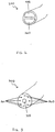
- Figure 2 a perspective view of a multi-lumen tube is depicted in accordance with an illustrative embodiment of the present invention. Specifically, Figure 2 depicts multi-lumen tube 200, which may be implemented in a reduced pressure treatment system, such as reduced pressure treatment system 100 in Figure 1 .
- Multi-lumen tube 200 includes two lumens. Specifically, multi-lumen tube 200 includes lumens 235 and 260. Although multi-lumen tube 200 includes two lumens 235 and 160, multi-lumen tube may have any number of lumens, such as three, four, or ten.
- one of lumens 235 and 260 is a delivery tube or source tube, such as delivery tube 135 and source tube 130 in Figure 1 .
- one of lumens 235 and 260 is a control tube, such as control tube 160 in Figure 1 .
- FIG. 3 a perspective view of a multi-lumen tube is depicted in accordance with an illustrative embodiment of the present invention.
- Figure 3 depicts multi-lumen tube 300, which may be implemented in a reduced pressure treatment system, such as reduced pressure treatment system 100 in Figure 1 .
- Multi-lumen tube 300 may be a non-limiting example of multi-lumen tube 200 in Figure 2 .
- Multi-lumen tube 300 includes nine lumens. Specifically, multi-lumen tube 300 includes lumen 335 and peripheral lumens 360. Although multi-lumen tube 300 shows peripheral lumens 360 as encircling lumen 335, the lumens in multi-lumen tube 300 may have any spatial configuration relative to one another.
- one of lumens 335 and 360 is a delivery tube or source tube, such as delivery tube 135 and source tube 130 in Figure 1 .
- one of lumens 335 and 360 is a control tube, such as control tube 160 in Figure 1 .
- the number of separate tubes included in the reduced pressure treatment system may be reduced to increase the usability of the reduced pressure treatment system in which the multi-lumen tube is included.
- FIG. 4 a flowchart illustrating a process for managing reduced pressure at a tissue site is depicted in accordance with an illustrative embodiment of the present invention.
- the process illustrated in Figure 4 may be implemented by a controller, such as controller 170 in Figure 1 , in conjunction with other components of a reduced pressure treatment system, such as components of reduced pressure treatment system 100 in Figure 1 .
- the process begins by determining a target reduced pressure (step 405).
- the process detects an actual reduced pressure at a tissue site using a single pressure sensor (step 410).
- the process compares the actual reduced pressure with the target reduced pressure to form a comparison (step 415).
- the process performs a reduced pressure management function based on the comparison (step 420).
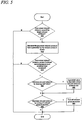
- FIG. 5 a flowchart illustrating a process for managing reduced pressure at a tissue site is depicted in accordance with an illustrative embodiment of the present invention.
- the process illustrated in Figure 5 may be implemented by a controller, such as controller 170 in Figure 1 , in conjunction with other components of a reduced pressure treatment system, such as components of reduced pressure treatment system 100 in Figure 1 .
- the process illustrated in Figure 5 provides illustrative embodiments and additional detail with respect to steps 415 and 420 in Figure 4 .
- the process begins by determining whether the actual reduced pressure exceeds the target reduced pressure (step 505). If the process determines that the actual reduced pressure does not exceed the target reduced pressure, the process terminates. Returning to step 505, if the process determines the actual reduced pressure exceeds the target reduced pressure, the process decreases the generated reduced pressure that is generated by the reduced pressure source (step 510).
- the process determines whether the actual reduced pressure exceeds the target reduced pressure by a predetermined threshold (step 515). If the process determines that the actual reduced pressure does not exceed the target reduced pressure by the predetermined threshold, the process terminates. Returning to step 515, if the process determines that the actual reduced pressure exceeds the target reduced pressure by a predetermined threshold, the process determines whether to decrease the reduced pressure by opening a relief valve (step 520). If the process determines to decrease the reduced pressure by opening a relief valve, the process opens the relief valve to decrease the actual reduced pressure at the tissue site (step 525).
- step 530 determines whether to decrease the reduced pressure by turning off the reduced pressure source. If the process determines to decrease the reduced pressure by turning off the reduced pressure source, the process turns off the reduced pressure source (step 535). The process then terminates. Returning to step 530, if the process determines not to decrease the reduced pressure by turning off the reduced pressure source, the process terminates.
- FIG. 6 a flowchart illustrating a process for managing reduced pressure at a tissue site is depicted in accordance with an illustrative example.
- the process illustrated in Figure 6 may be implemented by a controller, such as controller 170 in Figure 1 , in conjunction with other components of a reduced pressure treatment system, such as components of reduced pressure treatment system 100 in Figure 1 .
- the process illustrated in Figure 5 provides illustrative embodiments and additional detail with respect to steps 415 and 420 in Figure 4 .
- the process begins by determining whether the target reduced pressure exceeds the actual reduced pressure (step 605). If the process determines that the target reduced pressure does not exceed the actual reduced pressure, the process terminates. Returning to step 605, if the process determines that the target reduced pressure exceeds the actual reduced pressure, the process increases the generated reduced pressure that is generated by the reduced pressure source (step 610).
- the process determines whether the actual reduced pressure measured by the single pressure sensor is responsive to the increased generated reduced pressure (step 615). If the process determines that the actual reduced pressure measured by the single pressure sensor is responsive to the increased generated reduced pressure, the process terminates. Returning to step 615, if the process determines that the actual reduced pressure measured by the single pressure sensor is nonresponsive to the increased generated reduced pressure, the process emits a signal using an indicator (step 620). The process then terminates.
- FIG. 7 a flowchart illustrating a process for managing reduced pressure at a tissue site is depicted in accordance with an illustrative embodiment of the present invention.
- the process illustrated in Figure 7 may be implemented by a controller, such as controller 170 in Figure 1 , in conjunction with other components of a reduced pressure treatment system, such as components of reduced pressure treatment system 100 in Figure 1 .
- the process illustrated in Figure 7 provides illustrative embodiments and additional detail with respect to steps 615 and 620 in Figure 6 .
- the process begins by determining whether the actual reduced pressure at the tissue site increases within a predefined time period (step 705). If the process determines that the actual reduced pressure at the tissue site does not increase within a predefined time period, the process emits a signal using an indicator (step 710). The process then terminates.
- step 705 if the process determines that the actual reduced pressure at the tissue site increases within a predefined time period, the process determines whether the actual reduced pressure at the tissue site meets the target reduced pressure within a predefined time period (step 715). If the process determines that the actual reduced pressure at the tissue site does not meet the target reduced pressure within a predefined time period, the process emits a signal using the indicator (step 710). The process then terminates. Returning to step 715, if the process determines that the actual reduced pressure at the tissue site meets the target reduced pressure within a predefined time period, the process then terminates.
- the illustrative embodiments may be configured to be a light weight and low cost system that consumes less power than currently used reduced pressure treatment systems.
- the reductions in size and weight are particularly important when the system is to be used to treat low-severity wounds and wounds on ambulatory patients. These wounds and patients require a system that is unobtrusive and lightweight so that discomfort to the patient and hindrance of movement are minimized.
- One way in which cost, weight, and power consumption are minimized is through the use of only one sensor to measure pressure.
- traditional systems typically use two pressure sensors, one to measure pressure at the tissue site and one to measure pressure at the reduced pressure source.
- the elimination of the pressure sensor measuring pressure at the reduced pressure source allows significant reductions in the amount of electronic circuitry required and also the amount of power consumed by the system. Additionally, any circuitry and software used to compare the two sensor readings is eliminated.
- the illustrative embodiments enable the application of a predefined reduced pressure to tissue, while providing detection and notification of certain anomalous system conditions with fewer components than prior systems.
- the illustrative embodiments also eliminate the need to approximate the tissue site pressure using a measured value at the reduced pressure source. Further, determining the pressure directly at the tissue site, when included with the other features of the illustrative embodiments, allows the reduced pressure treatment system to detect leaks and blockages by observing pressure changes at the tissue site in response to operational changes made at the reduced pressure source.
Claims (13)
- Steuergerät (170) zum Verwalten von Unterdruck, gespeist durch eine Unterdruckquelle (110) an einer Gewebestelle (105), und gemessen durch einen Einzeldrucksensor (155), wobei das Steuergerät (170) konfiguriert ist:eine Änderung eines Betriebsparameters der Unterdruckquelle (110) zu erfassen, die auf eine Änderung des Unterdrucks deutet, der von der Unterdruckquelle (110) erzeugt wird,einen tatsächlichen Unterdruck an der Gewebestelle (105) unter Verwendung des Einzeldrucksensors (155) zu erfassen;ein Reagieren des vom Einzeldrucksensor (155) gemessenen tatsächlichen Unterdrucks auf eine Änderung des von dem Betriebsparameter erzeugten Unterdrucks zu bestimmen; undein Signal unter Verwendung einer Anzeige (180) als Reaktion auf den tatsächlichen Unterdruck an der Gewebestelle (105) auszugeben, der nicht auf eine Änderung des Unterdrucks reagiert, die durch die Unterdruckquelle (110) erzeugt wird.
- Steuergerät (170) nach Anspruch 1, weiter konfiguriert:einen Sollunterdruck für die Gewebestelle (105) zu bestimmen; undden durch den Einzeldrucksensor (155) nachgewiesenen tatsächlichen Unterdruck mit dem Sollunterdruck zu vergleichen.
- Steuergerät (170) nach Anspruch 2, weiter konfiguriert:
auf den tatsächlichen Unterdruck zu reagieren, der den Sollunterdruck übersteigt, durch Senken des erzeugten Unterdrucks, der durch die Unterdruckquelle (110) erzeugt wurde. - Steuergerät (170) nach Anspruch 2, weiter konfiguriert:
auf den Sollunterdruck zu reagieren, der den tatsächlichen Unterdruck an der Gewebestelle (105) übersteigt, durch Erhöhen des erzeugten Unterdrucks, der durch die Unterdruckquelle (110) erzeugt wurde. - Steuergerät (170) nach einem vorstehenden Anspruch, wobei das Reagieren durch Verfolgen bestimmt wird, ob der tatsächliche Unterdruck an der Gewebestelle (105) sich innerhalb eines vordefinierten Zeitraums ändert.
- Steuergerät (170) nach einem vorstehenden Anspruch, wobei das Reagieren durch Verfolgen bestimmt wird, ob der tatsächliche Unterdruck an der Gewebestelle (105) einem Sollunterdruck innerhalb eines vordefinierten Zeitraums genügt.
- Steuergerät (170) nach einem vorstehenden Anspruch, wobei der Betriebsparameter ein Strom ist, der von einem mit der Unterdruckquelle (110) verbundenen Motor verbraucht wird.
- Steuergerät (170) nach einem vorstehenden Anspruch, wobei der Betriebsparameter eine Geschwindigkeit von einem mit der Unterdruckquelle (110) verbundenen Motor ist.
- Steuergerät (170) nach einem vorstehenden Anspruch, wobei der Betriebsparameter eine Geschwindigkeit von einer mit der Unterdruckquelle (110) verbundenen chemischen Reaktion ist.
- Steuergerät (170) nach einem vorstehenden Anspruch, wobei das Reagieren durch Verfolgen bestimmt wird, ob der tatsächliche Unterdruck an der Gewebestelle (105) sich innerhalb eines Bereichs von 1 bis 10 Sekunden ändert.
- Steuergerät (170) nach einem vorstehenden Anspruch, wobei das Reagieren durch Verfolgen bestimmt wird, ob der tatsächliche Unterdruck an der Gewebestelle (105) sich innerhalb eines Bereichs von 4 bis 6 Sekunden ändert.
- Steuergerät (170) nach einem vorstehenden Anspruch, wobei die Anzeige (180) eine Leuchtdiode ist, wobei die Leuchtdiode als Reaktion auf den tatsächlichen Unterdruck an der Gewebestelle (105) leuchtet, der nicht auf die Erhöhung des erzeugten Unterdrucks reagiert.
- Steuergerät (170) nach einem vorstehenden Anspruch, wobei die Anzeige (180) eine Schall aussendende Vorrichtung ist, wobei die Schall aussendende Vorrichtung einen Schall in Reaktion auf den tatsächlichen Unterdruck an der Gewebestelle (105) aussendet, der nicht auf die Erhöhung des erzeugten Unterdrucks reagiert.
Priority Applications (1)
| Application Number | Priority Date | Filing Date | Title |
|---|---|---|---|
| EP18207374.2A EP3527235A1 (de) | 2007-02-09 | 2008-02-08 | System und verfahren zur verwaltung von verringertem druck an einer gewebestelle |
Applications Claiming Priority (3)
| Application Number | Priority Date | Filing Date | Title |
|---|---|---|---|
| US90055607P | 2007-02-09 | 2007-02-09 | |
| PCT/US2008/001730 WO2008100440A1 (en) | 2007-02-09 | 2008-02-08 | System and method for managing reduced pressure at a tissue site |
| EP08725372.0A EP2109472B2 (de) | 2007-02-09 | 2008-02-08 | System zur anwendung reduzierten drucks auf eine gewebestelle |
Related Parent Applications (2)
| Application Number | Title | Priority Date | Filing Date |
|---|---|---|---|
| EP08725372.0A Division EP2109472B2 (de) | 2007-02-09 | 2008-02-08 | System zur anwendung reduzierten drucks auf eine gewebestelle |
| EP08725372.0A Division-Into EP2109472B2 (de) | 2007-02-09 | 2008-02-08 | System zur anwendung reduzierten drucks auf eine gewebestelle |
Related Child Applications (1)
| Application Number | Title | Priority Date | Filing Date |
|---|---|---|---|
| EP18207374.2A Division EP3527235A1 (de) | 2007-02-09 | 2008-02-08 | System und verfahren zur verwaltung von verringertem druck an einer gewebestelle |
Publications (2)
| Publication Number | Publication Date |
|---|---|
| EP2974754A1 EP2974754A1 (de) | 2016-01-20 |
| EP2974754B1 true EP2974754B1 (de) | 2018-11-21 |
Family
ID=39690401
Family Applications (3)
| Application Number | Title | Priority Date | Filing Date |
|---|---|---|---|
| EP08725372.0A Active EP2109472B2 (de) | 2007-02-09 | 2008-02-08 | System zur anwendung reduzierten drucks auf eine gewebestelle |
| EP18207374.2A Withdrawn EP3527235A1 (de) | 2007-02-09 | 2008-02-08 | System und verfahren zur verwaltung von verringertem druck an einer gewebestelle |
| EP15179753.7A Active EP2974754B1 (de) | 2007-02-09 | 2008-02-08 | System zur verwaltung von reduziertem druck an einer gewebestelle |
Family Applications Before (2)
| Application Number | Title | Priority Date | Filing Date |
|---|---|---|---|
| EP08725372.0A Active EP2109472B2 (de) | 2007-02-09 | 2008-02-08 | System zur anwendung reduzierten drucks auf eine gewebestelle |
| EP18207374.2A Withdrawn EP3527235A1 (de) | 2007-02-09 | 2008-02-08 | System und verfahren zur verwaltung von verringertem druck an einer gewebestelle |
Country Status (15)
| Country | Link |
|---|---|
| US (3) | US8409170B2 (de) |
| EP (3) | EP2109472B2 (de) |
| JP (5) | JP5122586B2 (de) |
| KR (1) | KR101217918B1 (de) |
| CN (1) | CN101605568B (de) |
| AU (1) | AU2008216781B2 (de) |
| BR (1) | BRPI0806221A2 (de) |
| CA (1) | CA2673842C (de) |
| HK (1) | HK1135053A1 (de) |
| IL (1) | IL199778A0 (de) |
| MX (1) | MX2009008397A (de) |
| RU (1) | RU2428208C2 (de) |
| TW (2) | TWI372638B (de) |
| WO (1) | WO2008100440A1 (de) |
| ZA (1) | ZA200904308B (de) |
Families Citing this family (214)
| Publication number | Priority date | Publication date | Assignee | Title |
|---|---|---|---|---|
| GB0224986D0 (en) | 2002-10-28 | 2002-12-04 | Smith & Nephew | Apparatus |
| CN1822874B (zh) | 2003-07-22 | 2010-10-13 | 凯希特许有限公司 | 负压伤口治疗敷料 |
| GB0325129D0 (en) | 2003-10-28 | 2003-12-03 | Smith & Nephew | Apparatus in situ |
| US10058642B2 (en) | 2004-04-05 | 2018-08-28 | Bluesky Medical Group Incorporated | Reduced pressure treatment system |
| US8062272B2 (en) | 2004-05-21 | 2011-11-22 | Bluesky Medical Group Incorporated | Flexible reduced pressure treatment appliance |
| US7909805B2 (en) | 2004-04-05 | 2011-03-22 | Bluesky Medical Group Incorporated | Flexible reduced pressure treatment appliance |
| JP2009506878A (ja) | 2005-09-07 | 2009-02-19 | タイコ ヘルスケア グループ リミテッド パートナーシップ | マイクロポンプを有する自蔵創傷手当て |
| US8338402B2 (en) * | 2006-05-12 | 2012-12-25 | Smith & Nephew Plc | Scaffold |
| CA2872297C (en) | 2006-09-28 | 2016-10-11 | Smith & Nephew, Inc. | Portable wound therapy system |
| ES2564519T3 (es) | 2006-10-13 | 2016-03-23 | Bluesky Medical Group Inc. | Control de presión de una bomba de vacío médica |
| WO2008049029A2 (en) | 2006-10-17 | 2008-04-24 | Bluesky Medical Group Inc. | Auxiliary powered negative pressure wound therapy apparatuses and methods |
| US7967810B2 (en) | 2006-10-20 | 2011-06-28 | Mary Beth Kelley | Sub-atmospheric wound-care system |
| AU2008216870B2 (en) | 2007-02-09 | 2013-05-23 | Solventum Intellectual Properties Company | A breathable interface system for topical reduced pressure |
| JP5122586B2 (ja) * | 2007-02-09 | 2013-01-16 | ケーシーアイ ライセンシング インコーポレイテッド | 組織部位における減圧を管理するためのシステムおよび方法 |
| US10117977B2 (en) | 2007-03-14 | 2018-11-06 | The Board Of Trustees Of The Leland Stanford Junior University | Devices and methods for application of reduced pressure therapy |
| GB0712736D0 (en) * | 2007-07-02 | 2007-08-08 | Smith & Nephew | Apparatus |
| GB0712764D0 (en) | 2007-07-02 | 2007-08-08 | Smith & Nephew | Carrying Bag |
| US9408954B2 (en) | 2007-07-02 | 2016-08-09 | Smith & Nephew Plc | Systems and methods for controlling operation of negative pressure wound therapy apparatus |
| GB0712739D0 (en) | 2007-07-02 | 2007-08-08 | Smith & Nephew | Apparatus |
| GB0712763D0 (en) | 2007-07-02 | 2007-08-08 | Smith & Nephew | Apparatus |
| GB0715259D0 (en) | 2007-08-06 | 2007-09-12 | Smith & Nephew | Canister status determination |
| MX2010005553A (es) | 2007-11-21 | 2010-06-01 | Smith & Nephew | Aposito para heridas. |
| EP2217298B1 (de) * | 2007-11-21 | 2015-11-11 | T.J. Smith & Nephew Limited | Saugvorrichtung und verband |
| GB0722820D0 (en) | 2007-11-21 | 2008-01-02 | Smith & Nephew | Vacuum assisted wound dressing |
| EP3360519B1 (de) | 2007-11-21 | 2020-11-18 | Smith & Nephew plc | Wundauflage |
| US11253399B2 (en) | 2007-12-06 | 2022-02-22 | Smith & Nephew Plc | Wound filling apparatuses and methods |
| US20130096518A1 (en) | 2007-12-06 | 2013-04-18 | Smith & Nephew Plc | Wound filling apparatuses and methods |
| GB0723872D0 (en) | 2007-12-06 | 2008-01-16 | Smith & Nephew | Apparatus for topical negative pressure therapy |
| GB0723855D0 (en) | 2007-12-06 | 2008-01-16 | Smith & Nephew | Apparatus and method for wound volume measurement |
| GB0723874D0 (en) * | 2007-12-06 | 2008-01-16 | Smith & Nephew | Dressing |
| GB2455962A (en) | 2007-12-24 | 2009-07-01 | Ethicon Inc | Reinforced adhesive backing sheet, for plaster |
| US8377017B2 (en) | 2008-01-03 | 2013-02-19 | Kci Licensing, Inc. | Low-profile reduced pressure treatment system |
| DK2242522T3 (da) | 2008-01-08 | 2012-06-18 | Bluesky Medical Group Inc | Sårbehandling med uafbrudt variabelt undertryk og fremgangsmåde til kontrol heraf |
| CA3001382C (en) | 2008-02-14 | 2020-10-27 | Spiracur Inc. | Devices and methods for treatment of damaged tissue |
| KR101608548B1 (ko) | 2008-03-05 | 2016-04-01 | 케이씨아이 라이센싱 인코포레이티드 | 조직 부위에 감압을 가하고,조직 부위로부터 유체를 수집 및 저장하는 드레싱 및 방법 |
| US8298200B2 (en) | 2009-06-01 | 2012-10-30 | Tyco Healthcare Group Lp | System for providing continual drainage in negative pressure wound therapy |
| US9033942B2 (en) | 2008-03-07 | 2015-05-19 | Smith & Nephew, Inc. | Wound dressing port and associated wound dressing |
| US8021347B2 (en) | 2008-07-21 | 2011-09-20 | Tyco Healthcare Group Lp | Thin film wound dressing |
| EP2257320A2 (de) | 2008-03-12 | 2010-12-08 | Bluesky Medical Group Inc. | Vakuumverband und anwendungsverfahren |
| US8603013B2 (en) | 2008-03-13 | 2013-12-10 | Kci Licensing, Inc. | Pressure switches, transmitters, systems, and methods for monitoring a pressure at a tissue site |
| US9199012B2 (en) | 2008-03-13 | 2015-12-01 | Smith & Nephew, Inc. | Shear resistant wound dressing for use in vacuum wound therapy |
| US8177763B2 (en) | 2008-09-05 | 2012-05-15 | Tyco Healthcare Group Lp | Canister membrane for wound therapy system |
| US10912869B2 (en) | 2008-05-21 | 2021-02-09 | Smith & Nephew, Inc. | Wound therapy system with related methods therefor |
| US8414519B2 (en) | 2008-05-21 | 2013-04-09 | Covidien Lp | Wound therapy system with portable container apparatus |
| US8257326B2 (en) | 2008-06-30 | 2012-09-04 | Tyco Healthcare Group Lp | Apparatus for enhancing wound healing |
| AU2009268997B2 (en) | 2008-07-08 | 2015-04-02 | Smith & Nephew Inc. | Portable negative pressure wound therapy device |
| AU2009279525B2 (en) | 2008-08-08 | 2015-04-09 | Smith & Nephew Inc. | Wound dressing of continuous fibers |
| ES2653414T3 (es) * | 2008-08-08 | 2018-02-07 | Kci Licensing, Inc. | Sistemas de tratamiento con presión reducida con control de depósito |
| US8827983B2 (en) | 2008-08-21 | 2014-09-09 | Smith & Nephew, Inc. | Sensor with electrical contact protection for use in fluid collection canister and negative pressure wound therapy systems including same |
| US8251979B2 (en) | 2009-05-11 | 2012-08-28 | Tyco Healthcare Group Lp | Orientation independent canister for a negative pressure wound therapy device |
| US8216198B2 (en) | 2009-01-09 | 2012-07-10 | Tyco Healthcare Group Lp | Canister for receiving wound exudate in a negative pressure therapy system |
| US9414968B2 (en) | 2008-09-05 | 2016-08-16 | Smith & Nephew, Inc. | Three-dimensional porous film contact layer with improved wound healing |
| US8357131B2 (en) * | 2008-09-18 | 2013-01-22 | Kci Licensing, Inc. | Laminar dressings, systems, and methods for applying reduced pressure at a tissue site |
| US8158844B2 (en) | 2008-10-08 | 2012-04-17 | Kci Licensing, Inc. | Limited-access, reduced-pressure systems and methods |
| MX2011005075A (es) | 2008-11-14 | 2011-05-25 | Kci Licensing Inc | Bolsa para fluidos, sistema y metodo para almacenar fluido proveniente de un sitio de tejido. |
| EP3614114A1 (de) | 2008-11-25 | 2020-02-26 | KCI Licensing, Inc. | Vorrichtung zur abgabe von reduziertem druck auf körperoberflächen |
| WO2010080907A1 (en) | 2009-01-07 | 2010-07-15 | Spiracur Inc. | Reduced pressure therapy of the sacral region |
| US8162907B2 (en) | 2009-01-20 | 2012-04-24 | Tyco Healthcare Group Lp | Method and apparatus for bridging from a dressing in negative pressure wound therapy |
| US8728045B2 (en) * | 2009-03-04 | 2014-05-20 | Spiracur Inc. | Devices and methods to apply alternating level of reduced pressure to tissue |
| SE533726C2 (sv) * | 2009-04-30 | 2010-12-14 | Moelnlycke Health Care Ab | Apparat med negativt tryck för behandling av sår |
| US9421309B2 (en) | 2009-06-02 | 2016-08-23 | Kci Licensing, Inc. | Reduced-pressure treatment systems and methods employing hydrogel reservoir members |
| US20110196321A1 (en) | 2009-06-10 | 2011-08-11 | Tyco Healthcare Group Lp | Fluid Collection Canister Including Canister Top with Filter Membrane and Negative Pressure Wound Therapy Systems Including Same |
| US20100324516A1 (en) | 2009-06-18 | 2010-12-23 | Tyco Healthcare Group Lp | Apparatus for Vacuum Bridging and/or Exudate Collection |
| BR112012008087A2 (pt) | 2009-08-05 | 2016-03-01 | Tyco Healthcare | curativo de ferimento cirúrgico incorporando esferas de hidrogel conectadas tendo um eletrodo embutido naquele lugar |
| EP2464412A4 (de) | 2009-08-13 | 2014-08-20 | Michael Simms Shuler | Verfahren und verbandsysteme zur förderung der heilung von verletztem gewebe |
| KR101648975B1 (ko) * | 2009-09-22 | 2016-08-17 | 묄른뤼케 헬스 케어 에이비 | 환부의 부압 제어 장치 및 방법 |
| JP5805659B2 (ja) | 2009-12-22 | 2015-11-04 | スミス アンド ネフュー インコーポレーテッド | 陰圧閉鎖療法のための装置および方法 |
| AU2011207567B2 (en) * | 2010-01-20 | 2016-02-04 | Solventum Intellectual Properties Company | Wound-connection pads for fluid instillation and negative pressure wound therapy, and systems and methods |
| US8454580B2 (en) | 2010-03-12 | 2013-06-04 | Kci Licensing, Inc. | Adjustable reduced-pressure wound coverings |
| US8882730B2 (en) * | 2010-03-12 | 2014-11-11 | Kci Licensing, Inc. | Radio opaque, reduced-pressure manifolds, systems, and methods |
| US8430867B2 (en) * | 2010-03-12 | 2013-04-30 | Kci Licensing, Inc. | Reduced-pressure dressing connection pads, systems, and methods |
| US8814842B2 (en) | 2010-03-16 | 2014-08-26 | Kci Licensing, Inc. | Delivery-and-fluid-storage bridges for use with reduced-pressure systems |
| US9061095B2 (en) | 2010-04-27 | 2015-06-23 | Smith & Nephew Plc | Wound dressing and method of use |
| USRE48117E1 (en) | 2010-05-07 | 2020-07-28 | Smith & Nephew, Inc. | Apparatuses and methods for negative pressure wound therapy |
| US8795246B2 (en) | 2010-08-10 | 2014-08-05 | Spiracur Inc. | Alarm system |
| US8753322B2 (en) | 2010-08-10 | 2014-06-17 | Spiracur Inc. | Controlled negative pressure apparatus and alarm mechanism |
| GB201015656D0 (en) * | 2010-09-20 | 2010-10-27 | Smith & Nephew | Pressure control apparatus |
| JP2014500538A (ja) | 2010-10-12 | 2014-01-09 | タニス,ケヴィン ジェイ. | 医療機器 |
| US8986269B2 (en) * | 2010-11-11 | 2015-03-24 | Ulcerx Medical Inc. | Wound leakage vacuum collection device |
| US9364591B2 (en) * | 2010-11-17 | 2016-06-14 | Kci Licensing, Inc. | Systems and methods for managing reduced pressure at a plurality of wound sites |
| CN102058932B (zh) * | 2010-12-20 | 2013-03-06 | 惠州市华阳医疗电子有限公司 | 负压治疗系统的负压控制装置 |
| USD714433S1 (en) | 2010-12-22 | 2014-09-30 | Smith & Nephew, Inc. | Suction adapter |
| MX2013007304A (es) | 2010-12-22 | 2013-07-29 | Smith & Nephew Inc | Aparatos y metodos para terapia de heridas con presion negativa. |
| GB2488749A (en) | 2011-01-31 | 2012-09-12 | Systagenix Wound Man Ip Co Bv | Laminated silicone coated wound dressing |
| CN103517665B (zh) * | 2011-03-11 | 2016-06-29 | L&R国际有限责任及两合公司 | 用于内窥镜真空治疗的真空系统和内窥镜装置 |
| US9302034B2 (en) | 2011-04-04 | 2016-04-05 | Smith & Nephew, Inc. | Negative pressure wound therapy dressing |
| GB201106491D0 (en) | 2011-04-15 | 2011-06-01 | Systagenix Wound Man Ip Co Bv | Patterened silicone coating |
| WO2012145543A1 (en) * | 2011-04-20 | 2012-10-26 | Kci Licensing, Inc. | System and method for managing reduced pressure delivered to a tissue site |
| US9067003B2 (en) | 2011-05-26 | 2015-06-30 | Kalypto Medical, Inc. | Method for providing negative pressure to a negative pressure wound therapy bandage |
| WO2012168678A1 (en) | 2011-06-07 | 2012-12-13 | Smith & Nephew Plc | Wound contacting members and methods |
| WO2013015827A2 (en) * | 2011-07-26 | 2013-01-31 | Smith & Nephew Plc | Systems and methods for controlling operation of a reduced pressure therapy system |
| CN103764187B (zh) * | 2011-08-31 | 2017-03-08 | 凯希特许有限公司 | 用于体液的内联储存袋 |
| US9622914B2 (en) * | 2011-09-14 | 2017-04-18 | Kci Licensing, Inc. | Reduced-pressure systems and methods employing a leak-detection member |
| US9393354B2 (en) | 2011-11-01 | 2016-07-19 | J&M Shuler Medical, Inc. | Mechanical wound therapy for sub-atmospheric wound care system |
| US9084845B2 (en) | 2011-11-02 | 2015-07-21 | Smith & Nephew Plc | Reduced pressure therapy apparatuses and methods of using same |
| US10940047B2 (en) | 2011-12-16 | 2021-03-09 | Kci Licensing, Inc. | Sealing systems and methods employing a hybrid switchable drape |
| US9861532B2 (en) | 2011-12-16 | 2018-01-09 | Kci Licensing, Inc. | Releasable medical drapes |
| EP2626049B1 (de) * | 2012-02-11 | 2018-07-25 | Paul Hartmann AG | Wundtherapievorrichtung |
| CN107320791B (zh) | 2012-03-12 | 2022-02-08 | 史密夫及内修公开有限公司 | 用于减压伤口治疗的伤口敷料装置 |
| CA2867969C (en) | 2012-03-20 | 2020-03-24 | Smith & Nephew Plc | Controlling operation of a reduced pressure therapy system based on dynamic duty cycle threshold determination |
| US9427505B2 (en) | 2012-05-15 | 2016-08-30 | Smith & Nephew Plc | Negative pressure wound therapy apparatus |
| US11871901B2 (en) | 2012-05-20 | 2024-01-16 | Cilag Gmbh International | Method for situational awareness for surgical network or surgical network connected device capable of adjusting function based on a sensed situation or usage |
| BR112014029100A2 (pt) | 2012-05-23 | 2017-06-27 | Smith & Nephew | aparelhos e métodos para terapia de ferida por pressão negativa |
| EP3406231B1 (de) | 2012-08-01 | 2022-04-13 | Smith & Nephew plc | Wundverband und behandlungsverfahren damit |
| WO2014020440A1 (en) | 2012-08-01 | 2014-02-06 | Smith & Nephew Plc | Wound dressing |
| SG11201503860RA (en) | 2012-11-16 | 2015-06-29 | Kci Licensing Inc | Medical drape with pattern adhesive layers and method of manufacturing same |
| GB201222770D0 (en) | 2012-12-18 | 2013-01-30 | Systagenix Wound Man Ip Co Bv | Wound dressing with adhesive margin |
| JP6259510B2 (ja) * | 2013-03-14 | 2018-01-10 | ケーシーアイ ライセンシング インコーポレイテッド | 多微孔質導管 |
| WO2014143488A1 (en) | 2013-03-14 | 2014-09-18 | Kci Licensing, Inc. | Absorbent dressing with hybrid drape |
| US9737649B2 (en) | 2013-03-14 | 2017-08-22 | Smith & Nephew, Inc. | Systems and methods for applying reduced pressure therapy |
| BR112015021924A2 (pt) | 2013-03-14 | 2017-07-18 | Smith & Nephew Inc | sistemas e métodos para aplicar terapia de pressão reduzida |
| JP6427554B2 (ja) * | 2013-03-15 | 2018-11-21 | アトリウム メディカル コーポレーションAtrium Medical Corporation | 流体分析器および関連方法 |
| CN105377159B (zh) * | 2013-04-08 | 2018-06-12 | 波士顿科学医学有限公司 | 医疗系统与方法 |
| EP2994176B1 (de) | 2013-05-10 | 2020-07-08 | Smith & Nephew plc | Fluidischer verbinder zur spülung und absaugung von wunden |
| CN103330992B (zh) * | 2013-07-18 | 2016-03-30 | 苏州元禾医疗器械有限公司 | 辅助创面愈合的智能调节治疗系统 |
| JP6679483B2 (ja) * | 2013-08-13 | 2020-04-15 | スミス アンド ネフュー インコーポレイテッド | 減圧治療を実施するためのシステムおよび方法 |
| WO2015030963A1 (en) | 2013-08-26 | 2015-03-05 | Kci Licensing, Inc. | Dressing interface with moisture controlling feature and sealing function |
| EP3062753B1 (de) | 2013-10-28 | 2018-11-21 | KCI Licensing, Inc. | Hybrides dichtungsband |
| CN110652396B (zh) | 2013-10-30 | 2021-11-23 | 3M创新知识产权公司 | 具有不同大小的穿孔的敷件 |
| EP3513773A1 (de) | 2013-10-30 | 2019-07-24 | KCI Licensing, Inc. | Kondensatabsorbierendes und -ableitendes system |
| US9956120B2 (en) | 2013-10-30 | 2018-05-01 | Kci Licensing, Inc. | Dressing with sealing and retention interface |
| EP3744361A1 (de) | 2013-10-30 | 2020-12-02 | KCI Licensing, Inc. | Absorbierende leitung und system |
| CA2940730C (en) | 2014-02-28 | 2022-07-26 | Kci Licensing, Inc. | Hybrid drape having a gel-coated perforated mesh |
| US11026844B2 (en) | 2014-03-03 | 2021-06-08 | Kci Licensing, Inc. | Low profile flexible pressure transmission conduit |
| WO2015134749A2 (en) | 2014-03-06 | 2015-09-11 | Stryker Corporation | Medical/surgical waste collection unit with a light assembly separate from the primary display, the light assembly presenting informatin about the operation of the system by selectively outputting light |
| US10531977B2 (en) | 2014-04-17 | 2020-01-14 | Coloplast A/S | Thermoresponsive skin barrier appliances |
| US10406266B2 (en) | 2014-05-02 | 2019-09-10 | Kci Licensing, Inc. | Fluid storage devices, systems, and methods |
| AU2015259946B2 (en) * | 2014-05-15 | 2019-12-12 | Fisher & Paykel Healthcare Limited | Active smoke filtration for insufflation |
| EP3281616B1 (de) | 2014-06-05 | 2020-01-01 | KCI Licensing, Inc. | Verband mit flüssigkeitsaufnahme- und verteilungseigenschaften |
| JP6644764B2 (ja) | 2014-07-31 | 2020-02-12 | スミス アンド ネフュー インコーポレイテッド | 減圧療法を施すためのシステムおよび方法 |
| US10398604B2 (en) | 2014-12-17 | 2019-09-03 | Kci Licensing, Inc. | Dressing with offloading capability |
| EP3237032A2 (de) | 2014-12-22 | 2017-11-01 | Smith & Nephew PLC | Unterdruckwundtherapievorrichtung und -verfahren |
| WO2016109041A1 (en) | 2014-12-30 | 2016-07-07 | Smith & Nephew, Inc. | Systems and methods for applying reduced pressure therapy |
| EP3240586A1 (de) | 2014-12-30 | 2017-11-08 | Smith & Nephew, Inc | Systeme und verfahren zur anwendung von therapien mit reduziertem druck |
| US9549851B2 (en) | 2015-01-28 | 2017-01-24 | Novartis Ag | Surgical hand piece with integrated pressure sensor |
| CN113367890B (zh) | 2015-04-27 | 2023-02-21 | 史密夫及内修公开有限公司 | 减压装置 |
| US11246975B2 (en) | 2015-05-08 | 2022-02-15 | Kci Licensing, Inc. | Low acuity dressing with integral pump |
| WO2016184918A1 (en) * | 2015-05-18 | 2016-11-24 | Smith & Nephew Plc | Heat-assisted pumping systems for use in negative pressure wound therapy |
| US10076594B2 (en) | 2015-05-18 | 2018-09-18 | Smith & Nephew Plc | Fluidic connector for negative pressure wound therapy |
| EP3311765A4 (de) * | 2015-06-17 | 2019-02-20 | Olympus Corporation | Energiebehandlungswerkzeug |
| US10583228B2 (en) | 2015-07-28 | 2020-03-10 | J&M Shuler Medical, Inc. | Sub-atmospheric wound therapy systems and methods |
| EP3344205B1 (de) | 2015-09-01 | 2020-09-30 | KCI Licensing, Inc. | Verband mit erhöhter appositionskraft |
| JP6773773B2 (ja) | 2015-09-11 | 2020-10-21 | スミス アンド ネフュー インコーポレイテッド | 減陰圧療法を施すためのシステム及び方法 |
| EP3349807B1 (de) | 2015-09-17 | 2021-02-24 | 3M Innovative Properties Company | Hybride silikon- und acrylklebeabdeckung zur verwendung bei der wundbehandlung |
| ES2729154T5 (es) | 2015-12-30 | 2022-12-01 | Hartmann Paul Ag | Procedimientos y dispositivos para controlar la presión negativa en un sitio de herida |
| EP3187206B1 (de) * | 2015-12-30 | 2019-03-13 | Paul Hartmann AG | Verfahren und vorrichtungen für unterdruckwundbehandlung |
| CA3014354A1 (en) | 2016-02-12 | 2017-08-17 | Smith & Nephew, Inc. | Systems and methods for detecting operational conditions of reduced pressure therapy |
| CN114053031A (zh) | 2016-03-07 | 2022-02-18 | 史密夫及内修公开有限公司 | 利用整合到伤口敷料中的负压源的伤口治疗设备和方法 |
| CA3022184A1 (en) | 2016-04-26 | 2017-11-02 | Smith & Nephew Plc | Wound dressings and methods of use with integrated negative pressure source having a fluid ingress inhibition component |
| EP3452129B1 (de) | 2016-05-03 | 2022-03-23 | Smith & Nephew plc | Aktivierung und steuerung einer unterdruckwundtherapievorrichtung |
| CN109069710B (zh) | 2016-05-03 | 2022-04-12 | 史密夫及内修公开有限公司 | 优化到负压治疗系统中的负压源的功率传输 |
| EP3452131A1 (de) | 2016-05-03 | 2019-03-13 | Smith & Nephew PLC | Systeme und verfahren zum betrieb von unterdruckquellen in unterdrucktherapiesystemen |
| AU2017261814B2 (en) | 2016-05-13 | 2022-05-19 | Smith & Nephew, Inc. | Automatic wound coupling detection in negative pressure wound therapy systems |
| CA3034789A1 (en) | 2016-08-25 | 2018-03-01 | Smith & Nephew Plc | Absorbent negative pressure wound therapy dressing |
| CN106806064A (zh) * | 2016-08-27 | 2017-06-09 | 浙江保尔曼生物科技有限公司 | 伤口治疗仪器及其使用方法 |
| EP3290062A1 (de) * | 2016-08-31 | 2018-03-07 | B. Braun Surgical, S.A. | Medizinische vorrichtung, insbesondere zur behandlung von fisteln |
| EP3519001A1 (de) | 2016-09-30 | 2019-08-07 | Smith & Nephew PLC | Vorrichtungen und verfahren zur unterdruckwundbehandlung mit integrierter elektronik |
| JP7361606B2 (ja) | 2017-03-08 | 2023-10-16 | スミス アンド ネフュー ピーエルシー | 障害状態の存在下での陰圧創傷療法装置の制御 |
| WO2018206420A1 (en) | 2017-05-09 | 2018-11-15 | Smith & Nephew Plc | Redundant controls for negative pressure wound therapy systems |
| GB201718070D0 (en) | 2017-11-01 | 2017-12-13 | Smith & Nephew | Negative pressure wound treatment apparatuses and methods with integrated electronics |
| CN111065424A (zh) | 2017-09-13 | 2020-04-24 | 史密夫及内修公开有限公司 | 具有集成电子器件的负压伤口治疗设备及方法 |
| US11129636B2 (en) | 2017-10-30 | 2021-09-28 | Cilag Gmbh International | Surgical instruments comprising an articulation drive that provides for high articulation angles |
| GB201718072D0 (en) | 2017-11-01 | 2017-12-13 | Smith & Nephew | Negative pressure wound treatment apparatuses and methods with integrated electronics |
| GB201718054D0 (en) | 2017-11-01 | 2017-12-13 | Smith & Nephew | Sterilization of integrated negative pressure wound treatment apparatuses and sterilization methods |
| GB201718014D0 (en) | 2017-11-01 | 2017-12-13 | Smith & Nephew | Dressing for negative pressure wound therapy with filter |
| EP3703632B1 (de) | 2017-11-01 | 2024-04-03 | Smith & Nephew plc | Vorrichtungen und verfahren zur unterdruckwundbehandlung mit integrierter elektronik |
| DE102017131018A1 (de) | 2017-12-21 | 2019-06-27 | Paul Hartmann Ag | Verfahren zum Betreiben eines Unterdrucktherapiesystems |
| EP3727242B1 (de) | 2017-12-22 | 2022-03-09 | Coloplast A/S | Überwachungsvorrichtung für ein stomasystem mit einem verbinder zur verbindung mit einer grundplatte und einer zubehörvorrichtung |
| DK3729456T3 (da) | 2017-12-22 | 2022-03-07 | Coloplast As | Overvågningsanordning for et stomisystem og tilhørende fremgangsmåde til drift af en overvågningsanordning |
| EP4241744A3 (de) | 2017-12-22 | 2023-11-22 | Coloplast A/S | Grundplatte für eine stomavorrichtung und sensorbauteil für eine grundplatte und verfahren zur herstellung einer grundplatte und eines sensorbauteil |
| US10799385B2 (en) | 2017-12-22 | 2020-10-13 | Coloplast A/S | Ostomy appliance with layered base plate |
| EP3727222A1 (de) | 2017-12-22 | 2020-10-28 | Coloplast A/S | Sensorbauteil für künstlichen darmausgang und verfahren zur herstellung eines sensorbauteils |
| BR112020011316B1 (pt) | 2017-12-22 | 2023-12-05 | Coloplast A/S | Placa-base para um aparelho de ostomia, e, método para fabricar uma placa-base de um aparelho de ostomia |
| US10849781B2 (en) | 2017-12-22 | 2020-12-01 | Coloplast A/S | Base plate for an ostomy appliance |
| AU2018391323B2 (en) | 2017-12-22 | 2024-03-21 | Coloplast A/S | Base plate and sensor assembly of an ostomy system having a leakage sensor |
| US11654043B2 (en) | 2017-12-22 | 2023-05-23 | Coloplast A/S | Sensor assembly part and a base plate for a medical appliance and a method for manufacturing a base plate or a sensor assembly part |
| US11707377B2 (en) | 2017-12-22 | 2023-07-25 | Coloplast A/S | Coupling part with a hinge for a medical base plate and sensor assembly part |
| EP3727237A1 (de) | 2017-12-22 | 2020-10-28 | Coloplast A/S | Sensorbauteil und grundplatte für eine stomavorrichtung und vorrichtung zur verbindung mit einer grundplatte oder einem sensorbauteil |
| EP4248920A3 (de) | 2017-12-22 | 2023-12-27 | Coloplast A/S | Stomasystem, überwachungsvorrichtung und verfahren zur überwachung eines stomas |
| EP3727239B1 (de) | 2017-12-22 | 2024-02-07 | Coloplast A/S | Grundplatte für stoma, überwachungsvorrichtung und system für stoma |
| WO2019120441A1 (en) | 2017-12-22 | 2019-06-27 | Coloplast A/S | Sensor assembly part and a base plate for an ostomy appliance and a method for manufacturing a sensor assembly part and a base plate |
| EP3727234B1 (de) | 2017-12-22 | 2022-01-26 | Coloplast A/S | Stomavorrichtung mit winkelleckdetektion |
| US11627891B2 (en) | 2017-12-22 | 2023-04-18 | Coloplast A/S | Calibration methods for medical appliance tools |
| EP4275663A3 (de) | 2017-12-22 | 2024-01-17 | Coloplast A/S | Feuchtigkeitsdetektierende grundplatte für eine stomavorrichtung und system zur bestimmung der feuchtigkeitsausbreitung in einer grundplatte und/oder einem sensorbauteil |
| US10500084B2 (en) * | 2017-12-22 | 2019-12-10 | Coloplast A/S | Accessory devices of an ostomy system, and related methods for communicating leakage state |
| EP4074291A1 (de) | 2017-12-22 | 2022-10-19 | Coloplast A/S | Grundplatte für eine stomavorrichtung |
| WO2019120429A1 (en) | 2017-12-22 | 2019-06-27 | Coloplast A/S | Data collection schemes for an ostomy appliance and related methods |
| US11896322B2 (en) | 2017-12-28 | 2024-02-13 | Cilag Gmbh International | Sensing the patient position and contact utilizing the mono-polar return pad electrode to provide situational awareness to the hub |
| US11832899B2 (en) | 2017-12-28 | 2023-12-05 | Cilag Gmbh International | Surgical systems with autonomously adjustable control programs |
| US11857152B2 (en) | 2017-12-28 | 2024-01-02 | Cilag Gmbh International | Surgical hub spatial awareness to determine devices in operating theater |
| US11026751B2 (en) | 2017-12-28 | 2021-06-08 | Cilag Gmbh International | Display of alignment of staple cartridge to prior linear staple line |
| US11896443B2 (en) | 2017-12-28 | 2024-02-13 | Cilag Gmbh International | Control of a surgical system through a surgical barrier |
| US11612444B2 (en) | 2017-12-28 | 2023-03-28 | Cilag Gmbh International | Adjustment of a surgical device function based on situational awareness |
| US11109866B2 (en) | 2017-12-28 | 2021-09-07 | Cilag Gmbh International | Method for circular stapler control algorithm adjustment based on situational awareness |
| US20190201139A1 (en) | 2017-12-28 | 2019-07-04 | Ethicon Llc | Communication arrangements for robot-assisted surgical platforms |
| US11864728B2 (en) | 2017-12-28 | 2024-01-09 | Cilag Gmbh International | Characterization of tissue irregularities through the use of mono-chromatic light refractivity |
| US10624794B2 (en) | 2018-02-12 | 2020-04-21 | Healyx Labs, Inc. | Negative pressure wound therapy systems, devices, and methods |
| US11931285B2 (en) | 2018-02-20 | 2024-03-19 | Coloplast A/S | Sensor assembly part and a base plate for a medical appliance and a device for connecting to a base plate and/or a sensor assembly part |
| US11389188B2 (en) | 2018-03-08 | 2022-07-19 | Cilag Gmbh International | Start temperature of blade |
| EP3764955B1 (de) * | 2018-03-15 | 2024-01-10 | Coloplast A/S | Verfahren zum konfigurieren von stomameldungen und zugehörige zubehörgeräte |
| GB201804347D0 (en) | 2018-03-19 | 2018-05-02 | Smith & Nephew Inc | Securing control of settings of negative pressure wound therapy apparatuses and methods for using the same |
| US11090047B2 (en) | 2018-03-28 | 2021-08-17 | Cilag Gmbh International | Surgical instrument comprising an adaptive control system |
| BR112020019924A2 (pt) * | 2018-03-30 | 2021-01-05 | Ethicon Llc | Método de detecção de particulados de fumaça evacuada de um paciente, ajuste da velocidade da bomba com base na informação detectada e transmissão dos parâmetros funcionais do sistema para o controlador central |
| GB201806988D0 (en) | 2018-04-30 | 2018-06-13 | Quintanar Felix Clarence | Power source charging for negative pressure wound therapy apparatus |
| WO2019221869A1 (en) | 2018-05-16 | 2019-11-21 | Midwest Training and Development Services, LLC | Negative pressure wound apposition dressing system |
| GB201808438D0 (en) * | 2018-05-23 | 2018-07-11 | Smith & Nephew | Systems and methods for determining blockages in a negative pressure wound therapy system |
| GB201811449D0 (en) | 2018-07-12 | 2018-08-29 | Smith & Nephew | Apparatuses and methods for negative pressure wound therapy |
| WO2020046410A1 (en) | 2018-08-29 | 2020-03-05 | Aatru Medical, LLC | Negative pressure treatment including mechanical and chemical pump |
| USD898925S1 (en) | 2018-09-13 | 2020-10-13 | Smith & Nephew Plc | Medical dressing |
| US11612512B2 (en) | 2019-01-31 | 2023-03-28 | Coloplast A/S | Moisture detecting base plate for an ostomy appliance and a system for determining moisture propagation in a base plate and/or a sensor assembly part |
| US11291444B2 (en) | 2019-02-19 | 2022-04-05 | Cilag Gmbh International | Surgical stapling assembly with cartridge based retainer configured to unlock a closure lockout |
| CN110025832A (zh) * | 2019-03-25 | 2019-07-19 | 广东省医疗器械研究所 | 一种压力可调的引流控制器及其实现方法 |
| US11160917B2 (en) | 2020-01-22 | 2021-11-02 | J&M Shuler Medical Inc. | Negative pressure wound therapy barrier |
| USD959658S1 (en) | 2020-10-12 | 2022-08-02 | Stryker Corportation | Medical waste collection unit |
Citations (16)
| Publication number | Priority date | Publication date | Assignee | Title |
|---|---|---|---|---|
| EP0100672A2 (de) | 1982-08-03 | 1984-02-15 | Stryker Corporation | Unterdruck-Wunddränagesystem |
| EP0186762A1 (de) | 1984-11-16 | 1986-07-09 | Walter Beck | Vorrichtung zum Absaugen von Sekretflüssigkeit aus einer Wunde |
| US5429601A (en) | 1992-02-12 | 1995-07-04 | American Cyanamid Company | Aspiration control system |
| WO1996005873A1 (en) | 1994-08-22 | 1996-02-29 | Kinetic Concepts Inc. | Wound drainage equipment |
| EP0865304A1 (de) | 1995-11-14 | 1998-09-23 | KCI Medical Ltd. | Tragbare wundbehandlungsvorrichtung |
| WO2000021586A1 (en) | 1998-10-13 | 2000-04-20 | Kci Medical Limited | Negative pressure therapy using wall suction |
| WO2000061206A1 (en) | 1999-04-09 | 2000-10-19 | Kci Licensing, Inc. | Wound therapy device |
| US20030040687A1 (en) | 2001-08-24 | 2003-02-27 | Kci Licensing, Inc | Vacuum assisted tissue treatment system |
| WO2005025447A2 (en) | 2003-09-08 | 2005-03-24 | Microlin, L.C. | Device ανd method for wound therapy |
| US20060025727A1 (en) | 2003-09-16 | 2006-02-02 | Boehringer Laboratories, Inc. | Apparatus and method for suction-assisted wound healing |
| US7022113B2 (en) | 2001-07-12 | 2006-04-04 | Hill-Rom Services, Inc. | Control of vacuum level rate of change |
| WO2007013049A1 (en) | 2005-07-24 | 2007-02-01 | Carmeli Adahan | Wound closure and drainage system |
| US20070032763A1 (en) | 2005-08-08 | 2007-02-08 | Vogel Richard C | Wound irrigation device pressure monitoring and control system |
| US20070055209A1 (en) | 2005-09-07 | 2007-03-08 | Patel Harish A | Self contained wound dressing apparatus |
| WO2007088530A1 (en) | 2006-02-01 | 2007-08-09 | Carmeli Adahan | Suctioning system, method and kit |
| WO2007096817A1 (en) | 2006-02-24 | 2007-08-30 | Koninklijke Philips Electronics N.V. | Multi-colored led array with improved color uniformity |
Family Cites Families (249)
| Publication number | Priority date | Publication date | Assignee | Title |
|---|---|---|---|---|
| US1355846A (en) | 1920-02-06 | 1920-10-19 | David A Rannells | Medical appliance |
| US1885926A (en) * | 1931-06-24 | 1932-11-01 | Harry T Lewis | Liquid measuring device |
| US2381821A (en) * | 1940-10-25 | 1945-08-07 | Helleberg Tore | Device for determining the volume of gas or liquid in receptacles |
| US2378849A (en) * | 1940-10-25 | 1945-06-19 | Helleberg Tore | Device for determining the volume of gas or liquid in a receptacle |
| US2547758A (en) | 1949-01-05 | 1951-04-03 | Wilmer B Keeling | Instrument for treating the male urethra |
| US2632443A (en) | 1949-04-18 | 1953-03-24 | Eleanor P Lesher | Surgical dressing |
| GB692578A (en) | 1949-09-13 | 1953-06-10 | Minnesota Mining & Mfg | Improvements in or relating to drape sheets for surgical use |
| US2682873A (en) | 1952-07-30 | 1954-07-06 | Johnson & Johnson | General purpose protective dressing |
| NL189176B (nl) * | 1956-07-13 | 1900-01-01 | Hisamitsu Pharmaceutical Co | Pleister op basis van een synthetische rubber. |
| US2969057A (en) | 1957-11-04 | 1961-01-24 | Brady Co W H | Nematodic swab |
| US3066672A (en) | 1960-09-27 | 1962-12-04 | Jr William H Crosby | Method and apparatus for serial sampling of intestinal juice |
| DE1544868A1 (de) * | 1963-11-14 | 1969-06-26 | Bayer Ag | Trockene Pigmentzubereitungen zum Faerben von Kunststoffen |
| GB1052614A (de) * | 1964-06-04 | |||
| US3367332A (en) | 1965-08-27 | 1968-02-06 | Gen Electric | Product and process for establishing a sterile area of skin |
| US3419006A (en) | 1966-08-08 | 1968-12-31 | Union Carbide Corp | Novel dressing and use thereof |
| US3520300A (en) | 1967-03-15 | 1970-07-14 | Amp Inc | Surgical sponge and suction device |
| US3568675A (en) * | 1968-08-30 | 1971-03-09 | Clyde B Harvey | Fistula and penetrating wound dressing |
| US3585861A (en) * | 1969-06-05 | 1971-06-22 | Georgia Tech Res Inst | Method for volume measurement |
| US4141361A (en) * | 1970-02-09 | 1979-02-27 | Snyder Manufacturing Co., Incorporated | Evacuator |
| US3682180A (en) | 1970-06-08 | 1972-08-08 | Coilform Co Inc | Drain clip for surgical drain |
| BE789293Q (fr) | 1970-12-07 | 1973-01-15 | Parke Davis & Co | Pansement medico-chirugical pour brulures et lesions analogues |
| DE2108757C3 (de) | 1971-02-24 | 1974-01-17 | Egon Georg 8000 Muenchen Weishaar | Vorrichtung zur Blutabsaugung aus einer Operationswunde und Zuführung zu einer Herz-Lungen-Maschine |
| US3742952A (en) * | 1971-04-28 | 1973-07-03 | Alpha Ind Inc | Surgical suction pump assembly |
| US3779243A (en) * | 1971-10-15 | 1973-12-18 | J Tussey | Contamination free surgical evacuator |
| US3774611A (en) * | 1972-06-08 | 1973-11-27 | J Tussey | Stabilized contamination free surgical evacuator |
| US3744306A (en) * | 1972-06-30 | 1973-07-10 | R Krueger | Method and apparatus for measuring the ullage of a vessel |
| US3826254A (en) | 1973-02-26 | 1974-07-30 | Verco Ind | Needle or catheter retaining appliance |
| US3892229A (en) | 1973-12-06 | 1975-07-01 | Duane F Taylor | Apparatus for augmenting venous blood flow |
| DE2527706A1 (de) | 1975-06-21 | 1976-12-30 | Hanfried Dr Med Weigand | Einrichtung zum einleiten von kontrastmittel in einen kuenstlichen darmausgang |
| DE2640413C3 (de) | 1976-09-08 | 1980-03-27 | Richard Wolf Gmbh, 7134 Knittlingen | Katheter-Überwachungsgerät |
| NL7710909A (nl) | 1976-10-08 | 1978-04-11 | Smith & Nephew | Samengestelde hechtstrook. |
| GB1562244A (en) | 1976-11-11 | 1980-03-05 | Lock P M | Wound dressing materials |
| US4080970A (en) | 1976-11-17 | 1978-03-28 | Miller Thomas J | Post-operative combination dressing and internal drain tube with external shield and tube connector |
| US4091804A (en) | 1976-12-10 | 1978-05-30 | The Kendall Company | Compression sleeve |
| US4139004A (en) | 1977-02-17 | 1979-02-13 | Gonzalez Jr Harry | Bandage apparatus for treating burns |
| US4184510A (en) * | 1977-03-15 | 1980-01-22 | Fibra-Sonics, Inc. | Valued device for controlling vacuum in surgery |
| US4165748A (en) | 1977-11-07 | 1979-08-28 | Johnson Melissa C | Catheter tube holder |
| US4245637A (en) * | 1978-07-10 | 1981-01-20 | Nichols Robert L | Shutoff valve sleeve |
| SE414994B (sv) | 1978-11-28 | 1980-09-01 | Landstingens Inkopscentral | Venkateterforband |
| WO1980001139A1 (en) | 1978-12-06 | 1980-06-12 | Svedman Paul | Device for treating tissues,for example skin |
| US4266545A (en) | 1979-04-06 | 1981-05-12 | Moss James P | Portable suction device for collecting fluids from a closed wound |
| US4284079A (en) | 1979-06-28 | 1981-08-18 | Adair Edwin Lloyd | Method for applying a male incontinence device |
| US4261363A (en) | 1979-11-09 | 1981-04-14 | C. R. Bard, Inc. | Retention clips for body fluid drains |
| US4569348A (en) | 1980-02-22 | 1986-02-11 | Velcro Usa Inc. | Catheter tube holder strap |
| ATE14835T1 (de) | 1980-03-11 | 1985-08-15 | Schmid Eduard | Hauttransplantations-druckverband. |
| US4297995A (en) | 1980-06-03 | 1981-11-03 | Key Pharmaceuticals, Inc. | Bandage containing attachment post |
| US4375217A (en) | 1980-06-04 | 1983-03-01 | The Kendall Company | Compression device with pressure determination |
| US4529402A (en) * | 1980-07-08 | 1985-07-16 | Snyder Laboratories, Inc. | Closed wound suction evacuator with rotary valve |
| AU546785B2 (en) * | 1980-07-23 | 1985-09-19 | Commonwealth Of Australia, The | Open-loop controlled infusion of diabetics |
| US4333468A (en) | 1980-08-18 | 1982-06-08 | Geist Robert W | Mesentery tube holder apparatus |
| US4600015A (en) * | 1980-10-28 | 1986-07-15 | Antec Systems Limited | Patient monitoring apparatus and method |
| US4465485A (en) * | 1981-03-06 | 1984-08-14 | Becton, Dickinson And Company | Suction canister with unitary shut-off valve and filter features |
| US4392853A (en) | 1981-03-16 | 1983-07-12 | Rudolph Muto | Sterile assembly for protecting and fastening an indwelling device |
| US4373519A (en) | 1981-06-26 | 1983-02-15 | Minnesota Mining And Manufacturing Company | Composite wound dressing |
| US4392858A (en) | 1981-07-16 | 1983-07-12 | Sherwood Medical Company | Wound drainage device |
| US4419097A (en) | 1981-07-31 | 1983-12-06 | Rexar Industries, Inc. | Attachment for catheter tube |
| AU550575B2 (en) | 1981-08-07 | 1986-03-27 | Richard Christian Wright | Wound drainage device |
| SE429197B (sv) | 1981-10-14 | 1983-08-22 | Frese Nielsen | Anordning for behandling av sar |
| DE3146266A1 (de) | 1981-11-21 | 1983-06-01 | B. Braun Melsungen Ag, 3508 Melsungen | Kombinierte vorrichtung fuer eine medizinische saugdrainage |
| US4551139A (en) | 1982-02-08 | 1985-11-05 | Marion Laboratories, Inc. | Method and apparatus for burn wound treatment |
| DE3206130C2 (de) * | 1982-02-20 | 1986-07-03 | Walter 2000 Hamburg Nicolai | Einrichtung zur Ermittlung und Anzeige der Menge eines flüssigen oder festen Lagergutes |
| US4475909A (en) | 1982-05-06 | 1984-10-09 | Eisenberg Melvin I | Male urinary device and method for applying the device |
| EP0100148B1 (de) | 1982-07-06 | 1986-01-08 | Dow Corning Limited | Medizinischer chirurgischer Wundverband und Verfahren zu seiner Herstellung |
| NZ206837A (en) | 1983-01-27 | 1986-08-08 | Johnson & Johnson Prod Inc | Thin film adhesive dressing:backing material in three sections |
| US4534756A (en) * | 1983-04-11 | 1985-08-13 | Ivac Corporation | Fault detection apparatus and method for parenteral infusion system |
| US4548202A (en) | 1983-06-20 | 1985-10-22 | Ethicon, Inc. | Mesh tissue fasteners |
| US4540412A (en) | 1983-07-14 | 1985-09-10 | The Kendall Company | Device for moist heat therapy |
| US4509959A (en) | 1983-07-28 | 1985-04-09 | Greene & Kellogg, Inc. | Modular industrial oxygen concentrator |
| US4543100A (en) | 1983-11-01 | 1985-09-24 | Brodsky Stuart A | Catheter and drain tube retainer |
| GB8402351D0 (en) | 1984-01-30 | 1984-02-29 | Saggers M J | Inflatable garment |
| US4525374A (en) | 1984-02-27 | 1985-06-25 | Manresa, Inc. | Treating hydrophobic filters to render them hydrophilic |
| GB2157958A (en) | 1984-05-03 | 1985-11-06 | Ernest Edward Austen Bedding | Ball game net support |
| US4897081A (en) | 1984-05-25 | 1990-01-30 | Thermedics Inc. | Percutaneous access device |
| US5215522A (en) | 1984-07-23 | 1993-06-01 | Ballard Medical Products | Single use medical aspirating device and method |
| GB8419745D0 (en) * | 1984-08-02 | 1984-09-05 | Smith & Nephew Ass | Wound dressing |
| US4872450A (en) | 1984-08-17 | 1989-10-10 | Austad Eric D | Wound dressing and method of forming same |
| US4698060A (en) | 1984-08-20 | 1987-10-06 | Antonio Nicholas F D | Pressure regulation system |
| US4826494A (en) | 1984-11-09 | 1989-05-02 | Stryker Corporation | Vacuum wound drainage system |
| US4655754A (en) | 1984-11-09 | 1987-04-07 | Stryker Corporation | Vacuum wound drainage system and lipids baffle therefor |
| US4798583A (en) * | 1984-11-16 | 1989-01-17 | Walter Beck | Method and apparatus for aspirating secreted fluids from a wound |
| US4605399A (en) | 1984-12-04 | 1986-08-12 | Complex, Inc. | Transdermal infusion device |
| US4664652A (en) * | 1985-02-07 | 1987-05-12 | Snyder Laboratories, Inc. | Wound evacuator |
| US5037397A (en) | 1985-05-03 | 1991-08-06 | Medical Distributors, Inc. | Universal clamp |
| US4650462A (en) * | 1985-07-29 | 1987-03-17 | Minnesota Mining And Manufacturing Company | Irrigation system |
| US4640688A (en) | 1985-08-23 | 1987-02-03 | Mentor Corporation | Urine collection catheter |
| US4710165A (en) | 1985-09-16 | 1987-12-01 | Mcneil Charles B | Wearable, variable rate suction/collection device |
| US4758220A (en) | 1985-09-26 | 1988-07-19 | Alcon Laboratories, Inc. | Surgical cassette proximity sensing and latching apparatus |
| US4733659A (en) | 1986-01-17 | 1988-03-29 | Seton Company | Foam bandage |
| EP0256060A1 (de) | 1986-01-31 | 1988-02-24 | OSMOND, Roger L. W. | Absaugungssystem für wund-, magen- und darmdrainage |
| US4838883A (en) | 1986-03-07 | 1989-06-13 | Nissho Corporation | Urine-collecting device |
| JPS62281965A (ja) | 1986-05-29 | 1987-12-07 | テルモ株式会社 | カテ−テルおよびカテ−テル用固定部材 |
| GB8621884D0 (en) | 1986-09-11 | 1986-10-15 | Bard Ltd | Catheter applicator |
| GB2195255B (en) | 1986-09-30 | 1991-05-01 | Vacutec Uk Limited | Apparatus for vacuum treatment of an epidermal surface |
| US4743232A (en) | 1986-10-06 | 1988-05-10 | The Clinipad Corporation | Package assembly for plastic film bandage |
| DE3634569A1 (de) | 1986-10-10 | 1988-04-21 | Sachse Hans E | Kondomkatheter, ein harnroehrenkatheter zur verhinderung von aufsteigenden infektionen |
| JPS63135179A (ja) | 1986-11-26 | 1988-06-07 | 立花 俊郎 | 薬物の経皮投与具 |
| GB8628564D0 (en) | 1986-11-28 | 1987-01-07 | Smiths Industries Plc | Anti-foaming agent suction apparatus |
| GB8706116D0 (en) | 1987-03-14 | 1987-04-15 | Smith & Nephew Ass | Adhesive dressings |
| US4787888A (en) | 1987-06-01 | 1988-11-29 | University Of Connecticut | Disposable piezoelectric polymer bandage for percutaneous delivery of drugs and method for such percutaneous delivery (a) |
| US4863449A (en) | 1987-07-06 | 1989-09-05 | Hollister Incorporated | Adhesive-lined elastic condom cathether |
| US5176663A (en) | 1987-12-02 | 1993-01-05 | Pal Svedman | Dressing having pad with compressibility limiting elements |
| US4906240A (en) | 1988-02-01 | 1990-03-06 | Matrix Medica, Inc. | Adhesive-faced porous absorbent sheet and method of making same |
| US4981474A (en) * | 1988-02-16 | 1991-01-01 | Baxter Travenol Laboratories, Inc. | Body fluid drainage device |
| US4985019A (en) | 1988-03-11 | 1991-01-15 | Michelson Gary K | X-ray marker |
| GB8812803D0 (en) | 1988-05-28 | 1988-06-29 | Smiths Industries Plc | Medico-surgical containers |
| US4919654A (en) | 1988-08-03 | 1990-04-24 | Kalt Medical Corporation | IV clamp with membrane |
| US5000741A (en) | 1988-08-22 | 1991-03-19 | Kalt Medical Corporation | Transparent tracheostomy tube dressing |
| US4917112A (en) | 1988-08-22 | 1990-04-17 | Kalt Medical Corp. | Universal bandage with transparent dressing |
| EP0379416B1 (de) | 1989-01-16 | 1995-03-08 | Roussel-Uclaf | Azabicycloheptenderivate und ihre Salze, Verfahren zu ihrer Herstellung, ihre Verwendung als Arzneimittel und diese enthaltende Zubereitungen |
| GB8906100D0 (en) | 1989-03-16 | 1989-04-26 | Smith & Nephew | Laminates |
| US5261893A (en) | 1989-04-03 | 1993-11-16 | Zamierowski David S | Fastening system and method |
| US5527293A (en) | 1989-04-03 | 1996-06-18 | Kinetic Concepts, Inc. | Fastening system and method |
| US4969880A (en) | 1989-04-03 | 1990-11-13 | Zamierowski David S | Wound dressing and treatment method |
| US5100396A (en) | 1989-04-03 | 1992-03-31 | Zamierowski David S | Fluidic connection system and method |
| US5195995A (en) | 1989-05-09 | 1993-03-23 | Sherwood Medical Company | Control vacuum to measure gas flow |
| US5358494A (en) | 1989-07-11 | 1994-10-25 | Svedman Paul | Irrigation dressing |
| JP2719671B2 (ja) | 1989-07-11 | 1998-02-25 | 日本ゼオン株式会社 | 創傷被覆材 |
| US5232453A (en) | 1989-07-14 | 1993-08-03 | E. R. Squibb & Sons, Inc. | Catheter holder |
| GB2235877A (en) | 1989-09-18 | 1991-03-20 | Antonio Talluri | Closed wound suction apparatus |
| US5106629A (en) | 1989-10-20 | 1992-04-21 | Ndm Acquisition Corp. | Transparent hydrogel wound dressing |
| US5001924A (en) * | 1989-12-28 | 1991-03-26 | The United States Of America As Represented By The Administrator Of The National Aeronautics And Space Administration | Volumetric measurement of tank volume |
| US5112323A (en) * | 1990-02-08 | 1992-05-12 | Snyder Laboratories, Inc. | Wound evacuator |
| US5134994A (en) | 1990-02-12 | 1992-08-04 | Say Sam L | Field aspirator in a soft pack with externally mounted container |
| US5055198A (en) * | 1990-03-07 | 1991-10-08 | Shettigar U Ramakrishna | Autologous blood recovery membrane system and method |
| US5092858A (en) | 1990-03-20 | 1992-03-03 | Becton, Dickinson And Company | Liquid gelling agent distributor device |
| SE470052B (sv) | 1991-01-25 | 1993-11-01 | Lic Hygien Ab | Venkateterförband |
| US5160315A (en) | 1991-04-05 | 1992-11-03 | Minnesota Mining And Manufacturing Company | Combined adhesive strip and transparent dressing delivery system |
| US5149331A (en) | 1991-05-03 | 1992-09-22 | Ariel Ferdman | Method and device for wound closure |
| US5342329A (en) * | 1991-10-11 | 1994-08-30 | Inmed Ltda. | Portable disposable device for post-surgical suction |
| US5278100A (en) | 1991-11-08 | 1994-01-11 | Micron Technology, Inc. | Chemical vapor deposition technique for depositing titanium silicide on semiconductor wafers |
| US5636643A (en) | 1991-11-14 | 1997-06-10 | Wake Forest University | Wound treatment employing reduced pressure |
| US5645081A (en) | 1991-11-14 | 1997-07-08 | Wake Forest University | Method of treating tissue damage and apparatus for same |
| US5279550A (en) | 1991-12-19 | 1994-01-18 | Gish Biomedical, Inc. | Orthopedic autotransfusion system |
| US5167613A (en) | 1992-03-23 | 1992-12-01 | The Kendall Company | Composite vented wound dressing |
| FR2690617B1 (fr) | 1992-04-29 | 1994-06-24 | Cbh Textile | Pansement adhesif transparent. |
| PL307164A1 (en) | 1992-07-13 | 1995-05-02 | Pall Corp | Automatic system for and method of processing biological fluids |
| US5526683A (en) * | 1992-09-11 | 1996-06-18 | Maggio; Louis | Method and apparatus for determining the fullness and emptiness of silos |
| GB2271060B (en) | 1992-10-01 | 1996-04-03 | Huntleigh Technology Plc | An inflatable garment |
| DE4306478A1 (de) | 1993-03-02 | 1994-09-08 | Wolfgang Dr Wagner | Drainagevorrichtung, insbesondere Pleuradrainagevorrichtung, und Drainageverfahren |
| US5693080A (en) * | 1993-03-19 | 1997-12-02 | Wallsten Medical S.A. | Apparatus for medical treatment |
| US5342376A (en) | 1993-05-03 | 1994-08-30 | Dermagraphics, Inc. | Inserting device for a barbed tissue connector |
| US6241747B1 (en) | 1993-05-03 | 2001-06-05 | Quill Medical, Inc. | Barbed Bodily tissue connector |
| US5423737A (en) | 1993-05-27 | 1995-06-13 | New Dimensions In Medicine, Inc. | Transparent hydrogel wound dressing with release tab |
| US5344415A (en) | 1993-06-15 | 1994-09-06 | Deroyal Industries, Inc. | Sterile system for dressing vascular access site |
| US5497788A (en) | 1993-07-16 | 1996-03-12 | Tecnol Medical Products, Inc. | Wound closure device for viewing a wound and method |
| US5437651A (en) | 1993-09-01 | 1995-08-01 | Research Medical, Inc. | Medical suction apparatus |
| US5429593A (en) | 1993-12-23 | 1995-07-04 | Matory; Yvedt L. | Post-surgical, drainage accommodating, compression dressing |
| US5549584A (en) | 1994-02-14 | 1996-08-27 | The Kendall Company | Apparatus for removing fluid from a wound |
| US5562615A (en) * | 1994-02-28 | 1996-10-08 | Corpak, Inc. | Free flow detector for an enternal feeding pump |
| US5556375A (en) | 1994-06-16 | 1996-09-17 | Hercules Incorporated | Wound dressing having a fenestrated base layer |
| US5607388A (en) | 1994-06-16 | 1997-03-04 | Hercules Incorporated | Multi-purpose wound dressing |
| JP3679143B2 (ja) * | 1994-06-30 | 2005-08-03 | 株式会社ニデック | 灌流吸引装置 |
| US5664270A (en) | 1994-07-19 | 1997-09-09 | Kinetic Concepts, Inc. | Patient interface system |
| US5628230A (en) | 1994-11-01 | 1997-05-13 | Flam; Eric | Method and apparatus for testing the efficacy of patient support systems |
| US5645539A (en) * | 1994-11-14 | 1997-07-08 | Innocare One, Ltd. | Elongated medical channel assembly and method of preventing dislodgement |
| US5538502A (en) | 1994-12-27 | 1996-07-23 | Golda, Inc. | Surgical chest dressing |
| DE29504378U1 (de) | 1995-03-15 | 1995-09-14 | Mtg Medizinisch Tech Geraeteba | Elektronisch geregelte Niedervakuumpumpe für die Thorax- und Wunddrainage |
| DE19517699C2 (de) * | 1995-05-13 | 1999-11-04 | Wilhelm Fleischmann | Vorrichtung zur Vakuumversiegelung einer Wunde |
| DE19534417A1 (de) * | 1995-09-16 | 1997-03-20 | Fresenius Ag | Verfahren zum Überprüfen von mindestens einem im Dialysierflüssigkeitssystem einer Vorrichtung zur extrakorporalen Blutbehandlung angeordneten Filter |
| US5895869A (en) * | 1995-11-17 | 1999-04-20 | Mwi, Inc. | Method and apparatus for analyzing particulate matter |
| US5843007A (en) | 1996-04-29 | 1998-12-01 | Mcewen; James Allen | Apparatus and method for periodically applying a pressure waveform to a limb |
| US5653244A (en) | 1996-06-04 | 1997-08-05 | Circaid Medical Products, Inc. | Therapeutic compression garment |
| US5906206A (en) | 1996-06-04 | 1999-05-25 | Circaio Medical Products, Inc. | Therapeutic compression garment |
| WO1998025122A1 (en) | 1996-12-05 | 1998-06-11 | Bell Avon, Inc. | System and method for leak detection |
| EP0791814A3 (de) * | 1997-05-26 | 1997-11-26 | Martin Lehmann | Verfahren zum Prüfen von Leck und Apparat zum Testen von Leck |
| NL1006457C2 (nl) * | 1997-07-03 | 1999-01-05 | Polymedics N V | Drainagesysteem toe te passen bij een open wond, hierbij gebruikt element voor het aanbrengen van een drainagebuis of -slang en werkwijze voor het toepassen van het drainagesysteem. |
| US6135116A (en) * | 1997-07-28 | 2000-10-24 | Kci Licensing, Inc. | Therapeutic method for treating ulcers |
| US6420622B1 (en) | 1997-08-01 | 2002-07-16 | 3M Innovative Properties Company | Medical article having fluid control film |
| US6017493A (en) | 1997-09-26 | 2000-01-25 | Baxter International Inc. | Vacuum-assisted venous drainage reservoir for CPB systems |
| GB9719520D0 (en) | 1997-09-12 | 1997-11-19 | Kci Medical Ltd | Surgical drape and suction heads for wound treatment |
| AU755496B2 (en) | 1997-09-12 | 2002-12-12 | Kci Licensing, Inc. | Surgical drape and suction head for wound treatment |
| US5950238A (en) | 1998-01-29 | 1999-09-14 | Klein; Jeffrey A. | Post-liposuction breast compression garment and method for edema reduction |
| US6071267A (en) | 1998-02-06 | 2000-06-06 | Kinetic Concepts, Inc. | Medical patient fluid management interface system and method |
| US6176822B1 (en) | 1998-03-31 | 2001-01-23 | Impella Cardiotechnik Gmbh | Intracardiac blood pump |
| US6086450A (en) | 1998-08-13 | 2000-07-11 | Mankovitz; Roy J. | Brassieres which facilitate the drainage of lymphatic fluid from the breast area of the human female |
| US6488643B1 (en) | 1998-10-08 | 2002-12-03 | Kci Licensing, Inc. | Wound healing foot wrap |
| US6162960A (en) | 1999-01-25 | 2000-12-19 | Klein; Jeffrey A. | Compression sponge for wound care |
| DE19904603A1 (de) * | 1999-02-05 | 2000-08-10 | Goldschmidt Ag Th | Aminoxidgruppen enthaltende Maleinsäureanhydrid-Copolymere und ihre Verwendung als Dispergiermittel für Pigmente oder Füllstoffe |
| US6287316B1 (en) | 1999-03-26 | 2001-09-11 | Ethicon, Inc. | Knitted surgical mesh |
| US7947033B2 (en) | 1999-04-06 | 2011-05-24 | Kci Licensing Inc. | Systems and methods for detection of wound fluid blood and application of phototherapy in conjunction with reduced pressure wound treatment system |
| US7799004B2 (en) | 2001-03-05 | 2010-09-21 | Kci Licensing, Inc. | Negative pressure wound treatment apparatus and infection identification system and method |
| US6856821B2 (en) | 2000-05-26 | 2005-02-15 | Kci Licensing, Inc. | System for combined transcutaneous blood gas monitoring and vacuum assisted wound closure |
| US6695823B1 (en) * | 1999-04-09 | 2004-02-24 | Kci Licensing, Inc. | Wound therapy device |
| US6991643B2 (en) | 2000-12-20 | 2006-01-31 | Usgi Medical Inc. | Multi-barbed device for retaining tissue in apposition and methods of use |
| US6302653B1 (en) * | 1999-07-20 | 2001-10-16 | Deka Products Limited Partnership | Methods and systems for detecting the presence of a gas in a pump and preventing a gas from being pumped from a pump |
| US6402714B1 (en) * | 1999-11-12 | 2002-06-11 | Karl Storz Gmbh & Co., Kg | Apparatus and method for controlling high flow insufflation |
| US6824533B2 (en) | 2000-11-29 | 2004-11-30 | Hill-Rom Services, Inc. | Wound treatment apparatus |
| US6764462B2 (en) * | 2000-11-29 | 2004-07-20 | Hill-Rom Services Inc. | Wound treatment apparatus |
| IT1308687B1 (it) * | 1999-12-28 | 2002-01-09 | Gambro Dasco Spa | Metodo e dispositivo di rilevamento dell'accesso al sistemacardivascolare in un trattamento extracorporeo del sangue in una |
| TR200401397T4 (tr) | 2000-02-24 | 2004-07-21 | Venetec International, Inc. | Evrensel kateter takma sistemi. |
| RU2265620C2 (ru) * | 2000-04-20 | 2005-12-10 | Акцо Нобель Н.В. | Смола на основе разветвленного гидроксил-функционального сложного полиэфира и её использование в водных сшиваемых связующих композициях |
| DE10026466A1 (de) * | 2000-05-27 | 2001-11-29 | Basf Ag | Pigmentzubereitungen, enthaltend alkoxyliertes Polyethylenimin |
| US6585675B1 (en) * | 2000-11-02 | 2003-07-01 | Chf Solutions, Inc. | Method and apparatus for blood withdrawal and infusion using a pressure controller |
| US6855135B2 (en) | 2000-11-29 | 2005-02-15 | Hill-Rom Services, Inc. | Vacuum therapy and cleansing dressing for wounds |
| US6685681B2 (en) | 2000-11-29 | 2004-02-03 | Hill-Rom Services, Inc. | Vacuum therapy and cleansing dressing for wounds |
| US7070584B2 (en) * | 2001-02-20 | 2006-07-04 | Kci Licensing, Inc. | Biocompatible wound dressing |
| US6540705B2 (en) | 2001-02-22 | 2003-04-01 | Core Products International, Inc. | Ankle brace providing upper and lower ankle adjustment |
| US6878799B2 (en) * | 2001-03-12 | 2005-04-12 | King Industries, Inc. | Acid functional polymer dispersants |
| CN2479979Y (zh) | 2001-06-12 | 2002-03-06 | 刘贵真 | 经细管自动协助减压的气胸治疗仪 |
| US7025739B2 (en) * | 2001-08-09 | 2006-04-11 | Integra Lifesciences Corporation | System and method for treating elevated intracranial pressure |
| US6648862B2 (en) | 2001-11-20 | 2003-11-18 | Spheric Products, Ltd. | Personally portable vacuum desiccator |
| EP2623138B1 (de) | 2001-12-26 | 2020-08-05 | KCI Licensing, Inc. | Gelüfteter Vakuumverband und Verfahren |
| DE10204304A1 (de) * | 2002-02-01 | 2003-08-14 | Basf Ag | Pigmentgranulate |
| TWI224964B (en) | 2002-03-25 | 2004-12-11 | Molten Corp | Detecting device for cause of pressure sores |
| US8168848B2 (en) * | 2002-04-10 | 2012-05-01 | KCI Medical Resources, Inc. | Access openings in vacuum bandage |
| USD503509S1 (en) | 2002-07-01 | 2005-04-05 | Lightning2 Llc | Compression garment |
| US6860789B2 (en) | 2002-07-01 | 2005-03-01 | Lightning2 Llc | Compression garment |
| US6767188B2 (en) * | 2002-08-15 | 2004-07-27 | Becton, Dickinson And Company | Constant output fluidic system |
| US7846141B2 (en) | 2002-09-03 | 2010-12-07 | Bluesky Medical Group Incorporated | Reduced pressure treatment system |
| US6979324B2 (en) * | 2002-09-13 | 2005-12-27 | Neogen Technologies, Inc. | Closed wound drainage system |
| US7520872B2 (en) * | 2002-09-13 | 2009-04-21 | Neogen Technologies, Inc. | Closed wound drainage system |
| US7815616B2 (en) * | 2002-09-16 | 2010-10-19 | Boehringer Technologies, L.P. | Device for treating a wound |
| DE10245623A1 (de) * | 2002-09-30 | 2004-04-08 | Clariant Gmbh | Ester und Partialester aus mehrwertigen Alkoholen |
| CN2577848Y (zh) * | 2002-10-22 | 2003-10-08 | 王钦尧 | 一种负压吸引器 |
| GB0224986D0 (en) * | 2002-10-28 | 2002-12-04 | Smith & Nephew | Apparatus |
| JP4226425B2 (ja) | 2003-09-25 | 2009-02-18 | 本田技研工業株式会社 | ビスカスダンパ装置 |
| US7135007B2 (en) | 2003-11-21 | 2006-11-14 | Julius Zorn, Inc. | Compression garments and related methods |
| JP4590352B2 (ja) | 2003-12-22 | 2010-12-01 | メデラ ホールディング アーゲー | 排液装置および方法 |
| US7128735B2 (en) | 2004-01-02 | 2006-10-31 | Richard Scott Weston | Reduced pressure wound treatment appliance |
| US20050197647A1 (en) * | 2004-03-02 | 2005-09-08 | Dolliver Phillip B. | Surgical wound drain tube with flow control safeguards |
| US8062272B2 (en) * | 2004-05-21 | 2011-11-22 | Bluesky Medical Group Incorporated | Flexible reduced pressure treatment appliance |
| US8512219B2 (en) * | 2004-04-19 | 2013-08-20 | The Invention Science Fund I, Llc | Bioelectromagnetic interface system |
| WO2005105200A1 (en) * | 2004-04-22 | 2005-11-10 | Medtronic, Inc. | Branching catheter systems with diagnostic components |
| GB0508529D0 (en) * | 2005-04-27 | 2005-06-01 | Smith & Nephew | Sai with microstress |
| US9119907B2 (en) * | 2004-09-21 | 2015-09-01 | Zoll Medical Corporation | Digitally controlled aspirator |
| US20060229531A1 (en) | 2005-02-01 | 2006-10-12 | Daniel Goldberger | Blood monitoring system |
| JP4715751B2 (ja) * | 2004-11-18 | 2011-07-06 | 株式会社ジェイ・エム・エス | 自動腹膜灌流装置とその排液制御方法 |
| US7909754B2 (en) | 2005-02-24 | 2011-03-22 | Ethicon Endo-Surgery, Inc. | Non-invasive measurement of fluid pressure in an adjustable gastric band |
| CN2805782Y (zh) * | 2005-04-18 | 2006-08-16 | 杨克训 | 负压吸引器 |
| US7438705B2 (en) * | 2005-07-14 | 2008-10-21 | Boehringer Technologies, L.P. | System for treating a wound with suction and method detecting loss of suction |
| AU2006273684A1 (en) * | 2005-07-24 | 2007-02-01 | Carmeli Adahan | Suctioning system, method and kit |
| DE502005002730D1 (de) * | 2005-08-02 | 2008-03-20 | Moeller Medical Gmbh & Co Kg | Liquor-Drainagesystem |
| US7837673B2 (en) * | 2005-08-08 | 2010-11-23 | Innovative Therapies, Inc. | Wound irrigation device |
| US7648488B2 (en) | 2005-11-21 | 2010-01-19 | Pioneer Technology, Llc | Wound care system |
| US8267918B2 (en) * | 2006-03-14 | 2012-09-18 | Kci Licensing, Inc. | System and method for percutaneously administering reduced pressure treatment using a flowable manifold |
| US7252014B1 (en) * | 2006-04-17 | 2007-08-07 | Mocon, Inc. | Instrument and method for measuring the volume of a hermetically sealed variable volume and pressure conforming container |
| US7779625B2 (en) | 2006-05-11 | 2010-08-24 | Kalypto Medical, Inc. | Device and method for wound therapy |
| US20080009815A1 (en) * | 2006-07-10 | 2008-01-10 | Grabenkort Richard W | Vacuum Control System For A Breast Pump |
| US8652086B2 (en) * | 2006-09-08 | 2014-02-18 | Abbott Medical Optics Inc. | Systems and methods for power and flow rate control |
| TW200821001A (en) * | 2006-09-19 | 2008-05-16 | Kci Licensing Inc | Reduced pressure treatment system having blockage clearing and dual-zone pressure protection capabilities |
| US8366690B2 (en) | 2006-09-19 | 2013-02-05 | Kci Licensing, Inc. | System and method for determining a fill status of a canister of fluid in a reduced pressure treatment system |
| WO2008049029A2 (en) * | 2006-10-17 | 2008-04-24 | Bluesky Medical Group Inc. | Auxiliary powered negative pressure wound therapy apparatuses and methods |
| JP5122586B2 (ja) * | 2007-02-09 | 2013-01-16 | ケーシーアイ ライセンシング インコーポレイテッド | 組織部位における減圧を管理するためのシステムおよび方法 |
| JP4808811B2 (ja) * | 2007-02-20 | 2011-11-02 | ケーシーアイ ライセンシング インコーポレイテッド | 減圧治療システムにおいてキャニスタ係合外れ状態からリークを識別するシステム及び方法 |
| GB0715210D0 (en) | 2007-08-06 | 2007-09-12 | Smith & Nephew | Apparatus |
| EP2246080B1 (de) * | 2007-10-12 | 2016-02-10 | DEKA Products Limited Partnership | Extrakorporaler blutkreislauf |
| GB0723876D0 (en) | 2007-12-06 | 2008-01-16 | Smith & Nephew | Apparatus and method for topical negative pressure therapy |
| US8192388B2 (en) * | 2008-07-25 | 2012-06-05 | Baxter International Inc. | System and method for detecting access disconnection |
| WO2012145543A1 (en) * | 2011-04-20 | 2012-10-26 | Kci Licensing, Inc. | System and method for managing reduced pressure delivered to a tissue site |
-
2008
- 2008-02-08 JP JP2009549123A patent/JP5122586B2/ja active Active
- 2008-02-08 EP EP08725372.0A patent/EP2109472B2/de active Active
- 2008-02-08 AU AU2008216781A patent/AU2008216781B2/en active Active
- 2008-02-08 WO PCT/US2008/001730 patent/WO2008100440A1/en active Application Filing
- 2008-02-08 KR KR1020097018797A patent/KR101217918B1/ko not_active IP Right Cessation
- 2008-02-08 BR BRPI0806221-8A patent/BRPI0806221A2/pt not_active IP Right Cessation
- 2008-02-08 EP EP18207374.2A patent/EP3527235A1/de not_active Withdrawn
- 2008-02-08 MX MX2009008397A patent/MX2009008397A/es not_active Application Discontinuation
- 2008-02-08 RU RU2009124101/14A patent/RU2428208C2/ru not_active IP Right Cessation
- 2008-02-08 CA CA2673842A patent/CA2673842C/en active Active
- 2008-02-08 EP EP15179753.7A patent/EP2974754B1/de active Active
- 2008-02-08 CN CN2008800044356A patent/CN101605568B/zh active Active
- 2008-02-08 US US12/069,364 patent/US8409170B2/en active Active
- 2008-02-12 TW TW097104861A patent/TWI372638B/zh not_active IP Right Cessation
- 2008-02-12 TW TW101102361A patent/TW201219070A/zh unknown
-
2009
- 2009-06-19 ZA ZA200904308A patent/ZA200904308B/xx unknown
- 2009-07-09 IL IL199778A patent/IL199778A0/en unknown
-
2010
- 2010-04-09 HK HK10103488.1A patent/HK1135053A1/xx not_active IP Right Cessation
-
2012
- 2012-03-19 JP JP2012061520A patent/JP5542165B2/ja active Active
- 2012-10-24 JP JP2012234432A patent/JP5930466B2/ja active Active
-
2013
- 2013-02-28 US US13/780,438 patent/US9138515B2/en active Active
-
2015
- 2015-08-12 US US14/824,845 patent/US10016538B2/en active Active
-
2016
- 2016-02-09 JP JP2016022522A patent/JP6249459B2/ja active Active
-
2017
- 2017-11-15 JP JP2017219586A patent/JP6657165B2/ja active Active
Patent Citations (16)
| Publication number | Priority date | Publication date | Assignee | Title |
|---|---|---|---|---|
| EP0100672A2 (de) | 1982-08-03 | 1984-02-15 | Stryker Corporation | Unterdruck-Wunddränagesystem |
| EP0186762A1 (de) | 1984-11-16 | 1986-07-09 | Walter Beck | Vorrichtung zum Absaugen von Sekretflüssigkeit aus einer Wunde |
| US5429601A (en) | 1992-02-12 | 1995-07-04 | American Cyanamid Company | Aspiration control system |
| WO1996005873A1 (en) | 1994-08-22 | 1996-02-29 | Kinetic Concepts Inc. | Wound drainage equipment |
| EP0865304A1 (de) | 1995-11-14 | 1998-09-23 | KCI Medical Ltd. | Tragbare wundbehandlungsvorrichtung |
| WO2000021586A1 (en) | 1998-10-13 | 2000-04-20 | Kci Medical Limited | Negative pressure therapy using wall suction |
| WO2000061206A1 (en) | 1999-04-09 | 2000-10-19 | Kci Licensing, Inc. | Wound therapy device |
| US7022113B2 (en) | 2001-07-12 | 2006-04-04 | Hill-Rom Services, Inc. | Control of vacuum level rate of change |
| US20030040687A1 (en) | 2001-08-24 | 2003-02-27 | Kci Licensing, Inc | Vacuum assisted tissue treatment system |
| WO2005025447A2 (en) | 2003-09-08 | 2005-03-24 | Microlin, L.C. | Device ανd method for wound therapy |
| US20060025727A1 (en) | 2003-09-16 | 2006-02-02 | Boehringer Laboratories, Inc. | Apparatus and method for suction-assisted wound healing |
| WO2007013049A1 (en) | 2005-07-24 | 2007-02-01 | Carmeli Adahan | Wound closure and drainage system |
| US20070032763A1 (en) | 2005-08-08 | 2007-02-08 | Vogel Richard C | Wound irrigation device pressure monitoring and control system |
| US20070055209A1 (en) | 2005-09-07 | 2007-03-08 | Patel Harish A | Self contained wound dressing apparatus |
| WO2007088530A1 (en) | 2006-02-01 | 2007-08-09 | Carmeli Adahan | Suctioning system, method and kit |
| WO2007096817A1 (en) | 2006-02-24 | 2007-08-30 | Koninklijke Philips Electronics N.V. | Multi-colored led array with improved color uniformity |
Also Published As
Similar Documents
| Publication | Publication Date | Title |
|---|---|---|
| US10016538B2 (en) | System and method for managing reduced pressure at a tissue site | |
| US9925316B2 (en) | Apparatus and method for administering reduced pressure treatment to a tissue site | |
| AU2015201860B2 (en) | Apparatus and method for administering reduced pressure treatment to a tissue site |
Legal Events
| Date | Code | Title | Description |
|---|---|---|---|
| PUAI | Public reference made under article 153(3) epc to a published international application that has entered the european phase |
Free format text: ORIGINAL CODE: 0009012 |
|
| AC | Divisional application: reference to earlier application |
Ref document number: 2109472 Country of ref document: EP Kind code of ref document: P |
|
| AK | Designated contracting states |
Kind code of ref document: A1 Designated state(s): AT BE BG CH CY CZ DE DK EE ES FI FR GB GR HR HU IE IS IT LI LT LU LV MC MT NL NO PL PT RO SE SI SK TR |
|
| 17P | Request for examination filed |
Effective date: 20160715 |
|
| RBV | Designated contracting states (corrected) |
Designated state(s): AT BE BG CH CY CZ DE DK EE ES FI FR GB GR HR HU IE IS IT LI LT LU LV MC MT NL NO PL PT RO SE SI SK TR |
|
| RAP1 | Party data changed (applicant data changed or rights of an application transferred) |
Owner name: KCI LICENSING, INC. |
|
| RAP1 | Party data changed (applicant data changed or rights of an application transferred) |
Owner name: KCI LICENSING, INC. |
|
| STAA | Information on the status of an ep patent application or granted ep patent |
Free format text: STATUS: EXAMINATION IS IN PROGRESS |
|
| 17Q | First examination report despatched |
Effective date: 20170331 |
|
| RAP1 | Party data changed (applicant data changed or rights of an application transferred) |
Owner name: KCI LICENSING, INC. |
|
| GRAP | Despatch of communication of intention to grant a patent |
Free format text: ORIGINAL CODE: EPIDOSNIGR1 |
|
| STAA | Information on the status of an ep patent application or granted ep patent |
Free format text: STATUS: GRANT OF PATENT IS INTENDED |
|
| INTG | Intention to grant announced |
Effective date: 20180530 |
|
| RIN1 | Information on inventor provided before grant (corrected) |
Inventor name: LOCKE, CHRISTOPHER BRIAN Inventor name: BEARD, MARK STEPHAN JAMES |
|
| GRAS | Grant fee paid |
Free format text: ORIGINAL CODE: EPIDOSNIGR3 |
|
| GRAJ | Information related to disapproval of communication of intention to grant by the applicant or resumption of examination proceedings by the epo deleted |
Free format text: ORIGINAL CODE: EPIDOSDIGR1 |
|
| GRAL | Information related to payment of fee for publishing/printing deleted |
Free format text: ORIGINAL CODE: EPIDOSDIGR3 |
|
| STAA | Information on the status of an ep patent application or granted ep patent |
Free format text: STATUS: EXAMINATION IS IN PROGRESS |
|
| GRAR | Information related to intention to grant a patent recorded |
Free format text: ORIGINAL CODE: EPIDOSNIGR71 |
|
| STAA | Information on the status of an ep patent application or granted ep patent |
Free format text: STATUS: GRANT OF PATENT IS INTENDED |
|
| GRAA | (expected) grant |
Free format text: ORIGINAL CODE: 0009210 |
|
| STAA | Information on the status of an ep patent application or granted ep patent |
Free format text: STATUS: THE PATENT HAS BEEN GRANTED |
|
| INTC | Intention to grant announced (deleted) | ||
| AC | Divisional application: reference to earlier application |
Ref document number: 2109472 Country of ref document: EP Kind code of ref document: P |
|
| AK | Designated contracting states |
Kind code of ref document: B1 Designated state(s): AT BE BG CH CY CZ DE DK EE ES FI FR GB GR HR HU IE IS IT LI LT LU LV MC MT NL NO PL PT RO SE SI SK TR |
|
| INTG | Intention to grant announced |
Effective date: 20181016 |
|
| REG | Reference to a national code |
Ref country code: CH Ref legal event code: EP |
|
| REG | Reference to a national code |
Ref country code: IE Ref legal event code: FG4D |
|
| REG | Reference to a national code |
Ref country code: DE Ref legal event code: R096 Ref document number: 602008058068 Country of ref document: DE |
|
| REG | Reference to a national code |
Ref country code: AT Ref legal event code: REF Ref document number: 1066812 Country of ref document: AT Kind code of ref document: T Effective date: 20181215 |
|
| REG | Reference to a national code |
Ref country code: NL Ref legal event code: MP Effective date: 20181121 |
|
| REG | Reference to a national code |
Ref country code: AT Ref legal event code: MK05 Ref document number: 1066812 Country of ref document: AT Kind code of ref document: T Effective date: 20181121 |
|
| PG25 | Lapsed in a contracting state [announced via postgrant information from national office to epo] |
Ref country code: FI Free format text: LAPSE BECAUSE OF FAILURE TO SUBMIT A TRANSLATION OF THE DESCRIPTION OR TO PAY THE FEE WITHIN THE PRESCRIBED TIME-LIMIT Effective date: 20181121 Ref country code: LV Free format text: LAPSE BECAUSE OF FAILURE TO SUBMIT A TRANSLATION OF THE DESCRIPTION OR TO PAY THE FEE WITHIN THE PRESCRIBED TIME-LIMIT Effective date: 20181121 Ref country code: HR Free format text: LAPSE BECAUSE OF FAILURE TO SUBMIT A TRANSLATION OF THE DESCRIPTION OR TO PAY THE FEE WITHIN THE PRESCRIBED TIME-LIMIT Effective date: 20181121 Ref country code: AT Free format text: LAPSE BECAUSE OF FAILURE TO SUBMIT A TRANSLATION OF THE DESCRIPTION OR TO PAY THE FEE WITHIN THE PRESCRIBED TIME-LIMIT Effective date: 20181121 Ref country code: BG Free format text: LAPSE BECAUSE OF FAILURE TO SUBMIT A TRANSLATION OF THE DESCRIPTION OR TO PAY THE FEE WITHIN THE PRESCRIBED TIME-LIMIT Effective date: 20190221 Ref country code: ES Free format text: LAPSE BECAUSE OF FAILURE TO SUBMIT A TRANSLATION OF THE DESCRIPTION OR TO PAY THE FEE WITHIN THE PRESCRIBED TIME-LIMIT Effective date: 20181121 Ref country code: NO Free format text: LAPSE BECAUSE OF FAILURE TO SUBMIT A TRANSLATION OF THE DESCRIPTION OR TO PAY THE FEE WITHIN THE PRESCRIBED TIME-LIMIT Effective date: 20190221 Ref country code: LT Free format text: LAPSE BECAUSE OF FAILURE TO SUBMIT A TRANSLATION OF THE DESCRIPTION OR TO PAY THE FEE WITHIN THE PRESCRIBED TIME-LIMIT Effective date: 20181121 Ref country code: IS Free format text: LAPSE BECAUSE OF FAILURE TO SUBMIT A TRANSLATION OF THE DESCRIPTION OR TO PAY THE FEE WITHIN THE PRESCRIBED TIME-LIMIT Effective date: 20190321 |
|
| PG25 | Lapsed in a contracting state [announced via postgrant information from national office to epo] |
Ref country code: NL Free format text: LAPSE BECAUSE OF FAILURE TO SUBMIT A TRANSLATION OF THE DESCRIPTION OR TO PAY THE FEE WITHIN THE PRESCRIBED TIME-LIMIT Effective date: 20181121 Ref country code: PT Free format text: LAPSE BECAUSE OF FAILURE TO SUBMIT A TRANSLATION OF THE DESCRIPTION OR TO PAY THE FEE WITHIN THE PRESCRIBED TIME-LIMIT Effective date: 20190321 Ref country code: GR Free format text: LAPSE BECAUSE OF FAILURE TO SUBMIT A TRANSLATION OF THE DESCRIPTION OR TO PAY THE FEE WITHIN THE PRESCRIBED TIME-LIMIT Effective date: 20190222 Ref country code: SE Free format text: LAPSE BECAUSE OF FAILURE TO SUBMIT A TRANSLATION OF THE DESCRIPTION OR TO PAY THE FEE WITHIN THE PRESCRIBED TIME-LIMIT Effective date: 20181121 |
|
| PG25 | Lapsed in a contracting state [announced via postgrant information from national office to epo] |
Ref country code: IT Free format text: LAPSE BECAUSE OF FAILURE TO SUBMIT A TRANSLATION OF THE DESCRIPTION OR TO PAY THE FEE WITHIN THE PRESCRIBED TIME-LIMIT Effective date: 20181121 Ref country code: CZ Free format text: LAPSE BECAUSE OF FAILURE TO SUBMIT A TRANSLATION OF THE DESCRIPTION OR TO PAY THE FEE WITHIN THE PRESCRIBED TIME-LIMIT Effective date: 20181121 Ref country code: DK Free format text: LAPSE BECAUSE OF FAILURE TO SUBMIT A TRANSLATION OF THE DESCRIPTION OR TO PAY THE FEE WITHIN THE PRESCRIBED TIME-LIMIT Effective date: 20181121 Ref country code: PL Free format text: LAPSE BECAUSE OF FAILURE TO SUBMIT A TRANSLATION OF THE DESCRIPTION OR TO PAY THE FEE WITHIN THE PRESCRIBED TIME-LIMIT Effective date: 20181121 |
|
| REG | Reference to a national code |
Ref country code: DE Ref legal event code: R026 Ref document number: 602008058068 Country of ref document: DE |
|
| PLBI | Opposition filed |
Free format text: ORIGINAL CODE: 0009260 |
|
| PG25 | Lapsed in a contracting state [announced via postgrant information from national office to epo] |
Ref country code: EE Free format text: LAPSE BECAUSE OF FAILURE TO SUBMIT A TRANSLATION OF THE DESCRIPTION OR TO PAY THE FEE WITHIN THE PRESCRIBED TIME-LIMIT Effective date: 20181121 Ref country code: SK Free format text: LAPSE BECAUSE OF FAILURE TO SUBMIT A TRANSLATION OF THE DESCRIPTION OR TO PAY THE FEE WITHIN THE PRESCRIBED TIME-LIMIT Effective date: 20181121 Ref country code: RO Free format text: LAPSE BECAUSE OF FAILURE TO SUBMIT A TRANSLATION OF THE DESCRIPTION OR TO PAY THE FEE WITHIN THE PRESCRIBED TIME-LIMIT Effective date: 20181121 |
|
| PLAX | Notice of opposition and request to file observation + time limit sent |
Free format text: ORIGINAL CODE: EPIDOSNOBS2 |
|
| 26 | Opposition filed |
Opponent name: SMITH & NEPHEW, INC. Effective date: 20190819 Opponent name: PAUL HARTMANN AG Effective date: 20190821 |
|
| REG | Reference to a national code |
Ref country code: CH Ref legal event code: PL |
|
| PG25 | Lapsed in a contracting state [announced via postgrant information from national office to epo] |
Ref country code: MC Free format text: LAPSE BECAUSE OF FAILURE TO SUBMIT A TRANSLATION OF THE DESCRIPTION OR TO PAY THE FEE WITHIN THE PRESCRIBED TIME-LIMIT Effective date: 20181121 Ref country code: SI Free format text: LAPSE BECAUSE OF FAILURE TO SUBMIT A TRANSLATION OF THE DESCRIPTION OR TO PAY THE FEE WITHIN THE PRESCRIBED TIME-LIMIT Effective date: 20181121 Ref country code: LU Free format text: LAPSE BECAUSE OF NON-PAYMENT OF DUE FEES Effective date: 20190208 |
|
| REG | Reference to a national code |
Ref country code: BE Ref legal event code: MM Effective date: 20190228 |
|
| REG | Reference to a national code |
Ref country code: IE Ref legal event code: MM4A |
|
| PG25 | Lapsed in a contracting state [announced via postgrant information from national office to epo] |
Ref country code: CH Free format text: LAPSE BECAUSE OF NON-PAYMENT OF DUE FEES Effective date: 20190228 Ref country code: LI Free format text: LAPSE BECAUSE OF NON-PAYMENT OF DUE FEES Effective date: 20190228 |
|
| PLBB | Reply of patent proprietor to notice(s) of opposition received |
Free format text: ORIGINAL CODE: EPIDOSNOBS3 |
|
| PG25 | Lapsed in a contracting state [announced via postgrant information from national office to epo] |
Ref country code: IE Free format text: LAPSE BECAUSE OF NON-PAYMENT OF DUE FEES Effective date: 20190208 |
|
| PG25 | Lapsed in a contracting state [announced via postgrant information from national office to epo] |
Ref country code: BE Free format text: LAPSE BECAUSE OF NON-PAYMENT OF DUE FEES Effective date: 20190228 Ref country code: FR Free format text: LAPSE BECAUSE OF NON-PAYMENT OF DUE FEES Effective date: 20190228 |
|
| PG25 | Lapsed in a contracting state [announced via postgrant information from national office to epo] |
Ref country code: TR Free format text: LAPSE BECAUSE OF FAILURE TO SUBMIT A TRANSLATION OF THE DESCRIPTION OR TO PAY THE FEE WITHIN THE PRESCRIBED TIME-LIMIT Effective date: 20181121 |
|
| PLAY | Examination report in opposition despatched + time limit |
Free format text: ORIGINAL CODE: EPIDOSNORE2 |
|
| PLAB | Opposition data, opponent's data or that of the opponent's representative modified |
Free format text: ORIGINAL CODE: 0009299OPPO |
|
| PG25 | Lapsed in a contracting state [announced via postgrant information from national office to epo] |
Ref country code: MT Free format text: LAPSE BECAUSE OF NON-PAYMENT OF DUE FEES Effective date: 20190208 |
|
| R26 | Opposition filed (corrected) |
Opponent name: SMITH & NEPHEW, INC. Effective date: 20190819 |
|
| PLAH | Information related to despatch of examination report in opposition + time limit modified |
Free format text: ORIGINAL CODE: EPIDOSCORE2 |
|
| PLBC | Reply to examination report in opposition received |
Free format text: ORIGINAL CODE: EPIDOSNORE3 |
|
| REG | Reference to a national code |
Ref country code: GB Ref legal event code: 732E Free format text: REGISTERED BETWEEN 20201203 AND 20201209 |
|
| REG | Reference to a national code |
Ref country code: DE Ref legal event code: R081 Ref document number: 602008058068 Country of ref document: DE Owner name: SOLVENTUM INTELLECTUAL PROPERTIES CO. (N.D.GES, US Free format text: FORMER OWNER: KCI LICENSING, INC., SAN ANTONIO, TEX., US Ref country code: DE Ref legal event code: R081 Ref document number: 602008058068 Country of ref document: DE Owner name: 3M INNOVATIVE PROPERTIES COMPANY, ST. PAUL, US Free format text: FORMER OWNER: KCI LICENSING, INC., SAN ANTONIO, TEX., US |
|
| PG25 | Lapsed in a contracting state [announced via postgrant information from national office to epo] |
Ref country code: CY Free format text: LAPSE BECAUSE OF FAILURE TO SUBMIT A TRANSLATION OF THE DESCRIPTION OR TO PAY THE FEE WITHIN THE PRESCRIBED TIME-LIMIT Effective date: 20181121 |
|
| PG25 | Lapsed in a contracting state [announced via postgrant information from national office to epo] |
Ref country code: HU Free format text: LAPSE BECAUSE OF FAILURE TO SUBMIT A TRANSLATION OF THE DESCRIPTION OR TO PAY THE FEE WITHIN THE PRESCRIBED TIME-LIMIT; INVALID AB INITIO Effective date: 20080208 |
|
| REG | Reference to a national code |
Ref country code: CH Ref legal event code: PK Free format text: TITEL |
|
| APAW | Appeal reference deleted |
Free format text: ORIGINAL CODE: EPIDOSDREFNO |
|
| APAY | Date of receipt of notice of appeal deleted |
Free format text: ORIGINAL CODE: EPIDOSDNOA2O |
|
| APBM | Appeal reference recorded |
Free format text: ORIGINAL CODE: EPIDOSNREFNO |
|
| APBP | Date of receipt of notice of appeal recorded |
Free format text: ORIGINAL CODE: EPIDOSNNOA2O |
|
| APAH | Appeal reference modified |
Free format text: ORIGINAL CODE: EPIDOSCREFNO |
|
| APBM | Appeal reference recorded |
Free format text: ORIGINAL CODE: EPIDOSNREFNO |
|
| APBP | Date of receipt of notice of appeal recorded |
Free format text: ORIGINAL CODE: EPIDOSNNOA2O |
|
| APBQ | Date of receipt of statement of grounds of appeal recorded |
Free format text: ORIGINAL CODE: EPIDOSNNOA3O |
|
| PGFP | Annual fee paid to national office [announced via postgrant information from national office to epo] |
Ref country code: GB Payment date: 20230121 Year of fee payment: 16 Ref country code: DE Payment date: 20230119 Year of fee payment: 16 |
|
| REG | Reference to a national code |
Ref country code: GB Ref legal event code: 732E Free format text: REGISTERED BETWEEN 20240208 AND 20240214 |
|
| REG | Reference to a national code |
Ref country code: DE Ref legal event code: R081 Ref document number: 602008058068 Country of ref document: DE Owner name: SOLVENTUM INTELLECTUAL PROPERTIES CO. (N.D.GES, US Free format text: FORMER OWNER: 3M INNOVATIVE PROPERTIES COMPANY, ST. PAUL, MN, US |