EP2972191B1 - Solid water separation to sample spray water from a continuous caster - Google Patents
Solid water separation to sample spray water from a continuous caster Download PDFInfo
- Publication number
- EP2972191B1 EP2972191B1 EP14774964.2A EP14774964A EP2972191B1 EP 2972191 B1 EP2972191 B1 EP 2972191B1 EP 14774964 A EP14774964 A EP 14774964A EP 2972191 B1 EP2972191 B1 EP 2972191B1
- Authority
- EP
- European Patent Office
- Prior art keywords
- medium
- monitor
- sample
- separation device
- strand
- Prior art date
- Legal status (The legal status is an assumption and is not a legal conclusion. Google has not performed a legal analysis and makes no representation as to the accuracy of the status listed.)
- Active
Links
- 238000000926 separation method Methods 0.000 title claims description 35
- XLYOFNOQVPJJNP-UHFFFAOYSA-N water Substances O XLYOFNOQVPJJNP-UHFFFAOYSA-N 0.000 title claims description 31
- 239000007921 spray Substances 0.000 title claims description 29
- 239000007787 solid Substances 0.000 title description 14
- 239000002826 coolant Substances 0.000 claims description 27
- 238000000034 method Methods 0.000 claims description 26
- 239000002245 particle Substances 0.000 claims description 21
- 239000012530 fluid Substances 0.000 claims description 19
- 230000007797 corrosion Effects 0.000 claims description 18
- 238000005260 corrosion Methods 0.000 claims description 18
- 239000011148 porous material Substances 0.000 claims description 12
- 239000007788 liquid Substances 0.000 claims description 11
- 239000000203 mixture Substances 0.000 claims description 8
- 239000010419 fine particle Substances 0.000 claims description 7
- 239000000126 substance Substances 0.000 claims description 7
- 230000008569 process Effects 0.000 claims description 6
- 230000004044 response Effects 0.000 claims description 6
- 230000015572 biosynthetic process Effects 0.000 claims description 4
- 238000005070 sampling Methods 0.000 claims description 4
- 230000033116 oxidation-reduction process Effects 0.000 claims description 3
- 230000000704 physical effect Effects 0.000 claims description 3
- 239000003112 inhibitor Substances 0.000 claims description 2
- 230000002401 inhibitory effect Effects 0.000 claims description 2
- 238000005058 metal casting Methods 0.000 claims description 2
- 239000002184 metal Substances 0.000 description 20
- 229910052751 metal Inorganic materials 0.000 description 20
- 238000001816 cooling Methods 0.000 description 14
- 238000005507 spraying Methods 0.000 description 8
- 238000009749 continuous casting Methods 0.000 description 6
- 238000005259 measurement Methods 0.000 description 6
- 239000000463 material Substances 0.000 description 5
- 238000012544 monitoring process Methods 0.000 description 5
- KRHYYFGTRYWZRS-UHFFFAOYSA-N Fluorane Chemical compound F KRHYYFGTRYWZRS-UHFFFAOYSA-N 0.000 description 4
- 238000005266 casting Methods 0.000 description 4
- 230000000694 effects Effects 0.000 description 4
- 238000005516 engineering process Methods 0.000 description 3
- 230000004907 flux Effects 0.000 description 3
- 229910001338 liquidmetal Inorganic materials 0.000 description 3
- 239000000314 lubricant Substances 0.000 description 3
- 238000012806 monitoring device Methods 0.000 description 3
- 230000003068 static effect Effects 0.000 description 3
- 238000012546 transfer Methods 0.000 description 3
- RYGMFSIKBFXOCR-UHFFFAOYSA-N Copper Chemical compound [Cu] RYGMFSIKBFXOCR-UHFFFAOYSA-N 0.000 description 2
- XEEYBQQBJWHFJM-UHFFFAOYSA-N Iron Chemical compound [Fe] XEEYBQQBJWHFJM-UHFFFAOYSA-N 0.000 description 2
- UQSXHKLRYXJYBZ-UHFFFAOYSA-N Iron oxide Chemical compound [Fe]=O UQSXHKLRYXJYBZ-UHFFFAOYSA-N 0.000 description 2
- 229910000831 Steel Inorganic materials 0.000 description 2
- 239000002253 acid Substances 0.000 description 2
- 230000008859 change Effects 0.000 description 2
- 239000011362 coarse particle Substances 0.000 description 2
- 229910052802 copper Inorganic materials 0.000 description 2
- 239000010949 copper Substances 0.000 description 2
- 238000009826 distribution Methods 0.000 description 2
- 239000002923 metal particle Substances 0.000 description 2
- 239000013528 metallic particle Substances 0.000 description 2
- 238000010223 real-time analysis Methods 0.000 description 2
- 239000010959 steel Substances 0.000 description 2
- 238000012360 testing method Methods 0.000 description 2
- OKTJSMMVPCPJKN-UHFFFAOYSA-N Carbon Chemical compound [C] OKTJSMMVPCPJKN-UHFFFAOYSA-N 0.000 description 1
- QPLDLSVMHZLSFG-UHFFFAOYSA-N Copper oxide Chemical compound [Cu]=O QPLDLSVMHZLSFG-UHFFFAOYSA-N 0.000 description 1
- 239000005751 Copper oxide Substances 0.000 description 1
- KRHYYFGTRYWZRS-UHFFFAOYSA-M Fluoride anion Chemical compound [F-] KRHYYFGTRYWZRS-UHFFFAOYSA-M 0.000 description 1
- 206010061217 Infestation Diseases 0.000 description 1
- 239000000654 additive Substances 0.000 description 1
- 238000004458 analytical method Methods 0.000 description 1
- 229910052799 carbon Inorganic materials 0.000 description 1
- 230000002925 chemical effect Effects 0.000 description 1
- 238000006243 chemical reaction Methods 0.000 description 1
- 230000005494 condensation Effects 0.000 description 1
- 238000009833 condensation Methods 0.000 description 1
- 239000000498 cooling water Substances 0.000 description 1
- 229910000431 copper oxide Inorganic materials 0.000 description 1
- 238000005336 cracking Methods 0.000 description 1
- 238000005520 cutting process Methods 0.000 description 1
- 230000007547 defect Effects 0.000 description 1
- 230000008021 deposition Effects 0.000 description 1
- 239000006260 foam Substances 0.000 description 1
- -1 heat Substances 0.000 description 1
- 230000001771 impaired effect Effects 0.000 description 1
- 229910052742 iron Inorganic materials 0.000 description 1
- 230000007774 longterm Effects 0.000 description 1
- 239000013028 medium composition Substances 0.000 description 1
- 150000002739 metals Chemical class 0.000 description 1
- 230000002906 microbiologic effect Effects 0.000 description 1
- 239000003595 mist Substances 0.000 description 1
- 230000008520 organization Effects 0.000 description 1
- 239000000843 powder Substances 0.000 description 1
- 238000003825 pressing Methods 0.000 description 1
- 230000008439 repair process Effects 0.000 description 1
- 238000007493 shaping process Methods 0.000 description 1
- 229910001220 stainless steel Inorganic materials 0.000 description 1
- 239000010935 stainless steel Substances 0.000 description 1
- 230000008646 thermal stress Effects 0.000 description 1
- 239000002699 waste material Substances 0.000 description 1
Images


Classifications
-
- B—PERFORMING OPERATIONS; TRANSPORTING
- B01—PHYSICAL OR CHEMICAL PROCESSES OR APPARATUS IN GENERAL
- B01D—SEPARATION
- B01D29/00—Filters with filtering elements stationary during filtration, e.g. pressure or suction filters, not covered by groups B01D24/00 - B01D27/00; Filtering elements therefor
- B01D29/01—Filters with filtering elements stationary during filtration, e.g. pressure or suction filters, not covered by groups B01D24/00 - B01D27/00; Filtering elements therefor with flat filtering elements
- B01D29/03—Filters with filtering elements stationary during filtration, e.g. pressure or suction filters, not covered by groups B01D24/00 - B01D27/00; Filtering elements therefor with flat filtering elements self-supporting
-
- B—PERFORMING OPERATIONS; TRANSPORTING
- B01—PHYSICAL OR CHEMICAL PROCESSES OR APPARATUS IN GENERAL
- B01D—SEPARATION
- B01D29/00—Filters with filtering elements stationary during filtration, e.g. pressure or suction filters, not covered by groups B01D24/00 - B01D27/00; Filtering elements therefor
- B01D29/44—Edge filtering elements, i.e. using contiguous impervious surfaces
- B01D29/445—Bar screens
-
- B—PERFORMING OPERATIONS; TRANSPORTING
- B01—PHYSICAL OR CHEMICAL PROCESSES OR APPARATUS IN GENERAL
- B01D—SEPARATION
- B01D29/00—Filters with filtering elements stationary during filtration, e.g. pressure or suction filters, not covered by groups B01D24/00 - B01D27/00; Filtering elements therefor
- B01D29/88—Filters with filtering elements stationary during filtration, e.g. pressure or suction filters, not covered by groups B01D24/00 - B01D27/00; Filtering elements therefor having feed or discharge devices
- B01D29/90—Filters with filtering elements stationary during filtration, e.g. pressure or suction filters, not covered by groups B01D24/00 - B01D27/00; Filtering elements therefor having feed or discharge devices for feeding
- B01D29/908—Filters with filtering elements stationary during filtration, e.g. pressure or suction filters, not covered by groups B01D24/00 - B01D27/00; Filtering elements therefor having feed or discharge devices for feeding provoking a tangential stream
-
- B—PERFORMING OPERATIONS; TRANSPORTING
- B22—CASTING; POWDER METALLURGY
- B22D—CASTING OF METALS; CASTING OF OTHER SUBSTANCES BY THE SAME PROCESSES OR DEVICES
- B22D11/00—Continuous casting of metals, i.e. casting in indefinite lengths
- B22D11/16—Controlling or regulating processes or operations
- B22D11/22—Controlling or regulating processes or operations for cooling cast stock or mould
- B22D11/225—Controlling or regulating processes or operations for cooling cast stock or mould for secondary cooling
Definitions
- This invention relates generally to methods of, and apparatuses for accurately monitoring the properties of spray water used in a continuous caster system.
- continuous casting is a method of converting molten metal into semi-finished metal products such as billets, blooms, or slabs, and is useful for high volume and continuous operations.
- molten metal is collected in a special trough called a tundish and is then passed at a precisely controlled rate into a primary cooling zone.
- a solid mold often made of copper and often water/liquid cooled.
- the solid mold draws heat from the molten metal causing a solid "skin" of metal to form around a still liquid core. This solid clad liquid metal is referred to as a strand.
- the strand is then passed to a secondary cooling zone in which the stand is positioned within a spraying chamber where a liquid cooling medium (often water) is sprayed against the strand to further cool the metal.
- a liquid cooling medium often water
- spraying technology used in spraying chambers are described in US Patents 4,699,202 , 4,494,594 , 4,444,495 , 4,235,280 , 3,981,347 , 6,360,973 , 8,216,117 , and 7,905,271 .
- the strand While being sprayed the strand is also supported by rollers which prevent the solid walls of the strand from suffering breakouts (the leakage of liquid metal out from cracks in the strand's solid skin) caused by ferrostatic pressure (pressure caused by the different properties of the moving solid and liquid metal pressing against each other). The more solid strand is then passed on to subsequent cooling, shaping, and/or cutting steps.
- lubricants like mold powder such as that described in US 6,315,809
- lubricants are often placed on the solid mold, which are pulled into the secondary cooling zone by the strand. Once there the lubricants can react with super-hot water to form complex chemistries including highly reactive hydrofluoric acid. This, along with the intense pressure and temperature can cause additional particles to form from corrosion of bits of metal from the strand or from the pipes or walls of the spraying chamber itself. This in turn fills any collected cooling medium used for sampling with particles that can block piping used for collecting sprayed medium, or which can damage the monitors themselves.
- At least one embodiment of the invention is directed to a method of accurately sampling the properties of cooling medium that has been sprayed at a strand within a spray chamber of a continuous metal casting process.
- the method comprises the steps of: passing a sample of cooling medium through a separation device.
- the separation device comprises an angled flow surface constructed and arranged such that medium flows over the surface and fluid and fine particles from the medium sample pass through the flow surface and on to a monitor. Large particles in the medium do not pass through but rather slide down and off the angled flow surface thereby inhibiting the formation of clogs over the surface.
- the monitor is constructed and arranged to determine a chemical or physical property of the cooling medium. The absence of clogs allows for continuous monitoring of the medium during casting operations. Were clogs to form, the monitor would not receive sufficient/any samples and the casting operation would therefore be "blind" to effects resulting from medium composition.
- the method angled flow surface may comprise a plurality of extending members.
- the extending members may have a tapered configuration being wider at the top and narrower at the bottom.
- the tops of adjacent extending members may define a plurality of pores.
- the surface may be positioned at an angle of between 20° to 60° preferably between 30° to 50°, relative to a horizontal axis and allows for the passage of a sample through the pores plate at a rate of 10-100 liters/minute preferably at a rate of 20-80 liters/minute.
- the separation device is positioned directly below the strand.
- the surface may comprise a plurality of pores having a cross sectional aperture of between 0.15 mm to 1 mm and/or a cross sectional area of between 0.15 mm 2 to 1 mm2 ? preferably between 0.3 mm to 0.8 mm.
- the separation device may have a surface plate with a surface area of 0.1 to 1 m 2 , preferably between 0.3 to 0.8 m 2 , along which a plurality of slits are disposed.
- the sample may comprise mixed liquid composed by condensed liquid medium that was previously vapor in the spray chamber, direct spray water, and splashes.
- the monitor may be a device selected from the list consisting of: pH meter, fluorescence meter, oxidation reduction potential meter, corrosion measurer, temperature, conductivity and any combination thereof. But for the sample having passed through the separation device the flow of fluid to the monitor might have become clogged from particles present in the medium.
- the monitor may determine the degree of corrosion that is occurring in the spray chamber.
- the monitor may determine if the composition of the cooling medium will cause corrosion in excess of a pre-determined amount.
- the method may further comprise the step of raising or lowering the pH of the medium in response to a property measured by the monitor and dosing an appropriate amount of corrosion inhibitor.
- the sample may be fed into a scale pit or back into the spray chamber after it has been analyzed by a monitor.
- the particles passing on to the monitor may overwhelmingly comprise particles that have been introduced into the medium within 5 minutes of the monitor measuring them.
- Caster means a device utilizing a continuous casting process to convert molten metal into semi-finished solid metal products such as billets, blooms, or slabs.
- Cooling medium means a fluid (typically a liquid), sprayed at a strand to further cool and solidify the strand, it typically comprises or consists essentially of water but can also include or consist of mist and/or air.
- “Monitor” means a device constructed and arranged to measure at least one physical or chemical characteristic and to output a signal or display in response to that measurement, it includes but is not limited to any one or more of the methods and/or devices described in US Patent Applications 13/095,042 and/or 13/730,087 and US Patents 6,645,428 , 6,280,635 , 7,179,384 , 6312,644 , 6,358,746 , 7,601,789 , and 7,875,720 .
- Spray Chamber means a portion of a caster in which a strand is sprayed with a cooling medium to further solidify it, usually a spraying chamber is the secondary cooling zone positioned just after a solid mold (the primary cooling zone) but it can be the first source of cooling molten metal or can be positioned after other cooling devices or after other spray chambers.
- “Strand” means a stream of metal having a relatively solid outer skin and being molten within the skin.
- a sample of cooling medium passes from a continuous casting spray chamber through a separation device before it is passed on to a monitoring device which determines chemical and or physical properties of the cooling medium.
- the cooling medium can comprise water or can consist essentially of water.
- the cooling medium sample can be condensed from medium which vaporized when it came into contact with the strand.
- the medium can contain acid (such as hydrofluoric acid) formed from a reaction between the medium and a lubricant used in the mold.
- the medium can contain metal particles from corroded or eroded pieces of the strand or from the equipment (such as pipes or walls of the secondary cooling zone).
- the separation device is positioned below the strand.
- the water to be monitored is water specific to a highly localized area which would be indicative of water effects occurring at a specific piece of equipment or zone of the spray chamber.
- flow rate cannot be too high lest water from other locations slosh in and dilute the sample losing the information a specific locality's water would contain.
- the separation device can be constructed and arranged to allow the passage of fine metallic particles but block the passage of large metallic particles. This allows for the presence of sufficient metal in the sample to offer a useful gauge of corrosion occurring in the caster while allowing the sample to transit in a form easy to test and which is not likely to damage monitoring equipment.
- the separation device can be positioned and constructed and arranged such that it collects a representative sample of the liquid medium.
- slid-sieve allows for a flow of 10-100 liters/minute preferably for a flow of 20-80 liters/minute. At this speed, enough medium enters the monitor to provide a representative sample but not so much that it cancels out the various chemical effects occurring in the caster.
- the separation device is constructed and arranged to facilitate monitoring of variability in the water chemistry inside the caster spray chamber. To accomplish this there needs to be enough of a flow through the separation device to a monitoring device to get a reading that is reflecting the process on real time. As an example, to get a reading within 5 minutes from the process water, the water samples flow should be 10-25, preferably 15 liters per min as an optimum.
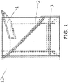
- the separation device (10) comprises a first angled surface (1) upon which a fluid sample will flow into the device. Fluid flows from the first angled surface (1) to a second angled surface (2).
- the second angled surface comprises one or more pores through which fluid and fine particles can flow but coarse matter will not flow. This allows for the separation of fine particles which have only recently corroded or eroded at a location extremely local to the separation device to pass along with the fluid towards a monitor but keep coarser matter which is often agglomerates of previously eroded/corroded matter residing in the spray chamber.
- the fluid then passes onto a third angled surface (3).
- a flow of fluid running along the second angled surface (2) carries coarse particles off and away from the second angled surface (2) without them passing down to the third angled surface (3).
- the angle(s) of the first and/or second angled surfaces (1, 2) are established such that an optimal flow rate is achieved.
- the angle is between 20° to 60° preferably between 30° to 50°, relative to a horizontal axis. This allows fluid to wash away deposited particles from the plate's surface while also allowing fluid containing a representative amount of fine particles to pass through to the third angled surface (3).
- the angled surface (3) collects the now filtered fluid sample and passes it on to a monitoring device.
- the second angled surface may comprise one or more or a plurality of pores through which the fluid and fine matter can flow but through which the coarse material cannot flow.
- Such pores may have a cross-sectional area of between 0.15 mm 2 to 1 mm 2 and/or a cross sectional aperture of between 0.15 mm to 1 mm, preferably between 0.30 mm 2 to 0.8 mm 2 .
- the surface area of the filter plate (2) is preferably 0.1 to 1 m 2 , more preferably between 0.3 to 0.8 m 2
- the size of the pores can be proportional to the tendency of the location where the separation device is located to accumulate particles.
- part or all of the separation device is constructed out of a material that is resistant to acid, heat, and/or water based corrosion. It may be in part or in all constructed out of stainless steel.
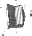
- the second angled surface (2) may comprise one or more slid-sieves.
- the slid sieve comprise a plurality of extending members (5).
- the extending members have a tapered configuration such that their upper surface (upon which a flow of medium (7) will land) is wider than their lower surface.
- Narrow slot openings (4) between adjacent extending members (5) define the pores through which fine particles and fluid will pass but through which coarse matter (8) shall not.
- the slot openings (4) may be positioned to extend at least in part along a vertical and horizontal axis. As a result medium will slosh along it until it falls off its lower end. While so traversing the slot openings (4), fluid and fine particles have a long period of time to become separated from the coarse matter. As illustrated in FIG. 3 , the slot openings (4) may be positioned to extend at least in perpendicular to the vertical and horizontal axes. As illustrated in FIG. 4 the extending members (5) may be supported by engagement to one or more support rods (6). An array of extending members (5) and support rods (6) may define in part or in totality the second angled surface (2).
- the separation device may be constructed and arranged so that the third angled surface (3) directs the flow of fluid in a direction generally perpendicular to the flow direction of the second angled surface (2).
- the samples passes on from the separation device to a monitor device selected from the list consisting of: pH meter, fluoride measurement prober, oxidation reduction potential meter, corrosion measurer, conductivity, temperature, and any combination thereof.
- a monitor device selected from the list consisting of: pH meter, fluoride measurement prober, oxidation reduction potential meter, corrosion measurer, conductivity, temperature, and any combination thereof.
- the arrangements of one or more of the components of the separation device (10) are particularly well suited for the nature of a caster system spray chamber. Because casters often cast metals at high speeds, slight changes in the thermal environment can cause large variations in heat flux in the mold. As a result differing or inconsistent properties or effects of the cooling medium can result in widely different rates of heat transfer and thermal stress. For example, certain materials if present in the cooling medium will result in random deposits on the mold that lead to uneven heat transfer. Similarly certain particles in water can form random copper oxide formation on copper molds or microbiological infestations of medium can result in random iron oxide deposition on molds. Other materials such as organic carbon may cause some of the medium to foam which inconsistently alters the cooling properties of some of the medium.
- the angle of the surface and/or the flow rates of medium over the surface and/or fluid with fines through the pores are optimized for the particular coarseness, population of particles sizes, and feed rate of medium in a continuous casting operation.
- the sample that has passed on through the separation device is then analyzed by a monitor to determine the degree of corrosion that is occurring.
- the composition of spray water that is then sprayed at the strand is changed to reduce corrosion.
- the sample that has passed on through the separation device is then analyzed to determine if it will cause corrosion in excess of a pre-determined amount.
- the composition of spray water that is then sprayed at the strand is changed to reduce corrosion.
- the pH of further spray in response to a measured parameter of the spray medium sample, is raised or lowered and/or one or more chemical additives are added to the medium.
- the sprayed cooling medium in response to a measured parameter of the spray medium sample, the sprayed cooling medium either is or is not recirculated and re-sprayed at the strand.
- the sprayed cooling medium in response to a measured parameter of the spray medium sample, the sprayed cooling medium either is stored for future use or is disposed of as waste.
- the sample that has passed through the separation device is then analyzed to determine if it the metal particles within it are from the strand or from particular pieces of caster equipment. Based on this analysis decisions can be made regarding whether to change a process condition (metal feed rate, metal temperature, spray properties), the composition of the strand, to repair/replace equipment, and how long to maintain caster operation, to cease/commence operation, and any combination thereof.
- a process condition metal feed rate, metal temperature, spray properties
- the composition of the strand to repair/replace equipment, and how long to maintain caster operation, to cease/commence operation, and any combination thereof.
- the ratio of strand derived metal to equipment derived metal is so great that but for passing through the slid sieve, the ratio would have drowned out the signal for detecting the equipment derived metal and would have resulted in the corrosion of the equipment going undetected or its apparent magnitude being erroneous.
- the monitor is used to determine the rate at which vaporous medium is condensing into liquid medium, and but for the removal of the particles, the monitor would have provided an erroneously low rate of condensation because the particles were preventing entry of the samples into the monitor.
- the best orientation was the one combining the best water flow collection with a minimum of particles entering the sampling device. As shown on the table 1, the best orientation was horizontal with an angle for the grid of 45 degrees. Table 1: orientation tests Angle Static screen position Water collected (L)* Water collected (%) Particles passing through (%) Ratio water/ particles 45 Vertical 2.75 69 36 2 horizontal 3.5 88 17 5 60 Vertical 1.75 44 21 2 horizontal 3.8 95 32 3 * Water flow collected at OXY2 was between 0.1 to 3.6 m3/h depending on steel grade produced and casting speed.
Landscapes
- Chemical & Material Sciences (AREA)
- Chemical Kinetics & Catalysis (AREA)
- Engineering & Computer Science (AREA)
- Mechanical Engineering (AREA)
- Sampling And Sample Adjustment (AREA)
- Life Sciences & Earth Sciences (AREA)
- Testing Resistance To Weather, Investigating Materials By Mechanical Methods (AREA)
- Health & Medical Sciences (AREA)
- Physics & Mathematics (AREA)
- Analytical Chemistry (AREA)
- Biochemistry (AREA)
- General Health & Medical Sciences (AREA)
- General Physics & Mathematics (AREA)
- Immunology (AREA)
- Pathology (AREA)
- Hydrology & Water Resources (AREA)
- Manufacture And Refinement Of Metals (AREA)
- Continuous Casting (AREA)
- Investigating And Analyzing Materials By Characteristic Methods (AREA)
Applications Claiming Priority (2)
| Application Number | Priority Date | Filing Date | Title |
|---|---|---|---|
| US13/800,842 US9682334B2 (en) | 2013-03-13 | 2013-03-13 | Solid water separation to sample spray water from a continuous caster |
| PCT/US2014/016055 WO2014158402A1 (en) | 2013-03-13 | 2014-02-12 | Solid water separation to sample spray water from a continuous caster |
Publications (3)
| Publication Number | Publication Date |
|---|---|
| EP2972191A1 EP2972191A1 (en) | 2016-01-20 |
| EP2972191A4 EP2972191A4 (en) | 2016-11-02 |
| EP2972191B1 true EP2972191B1 (en) | 2018-06-13 |
Family
ID=51522788
Family Applications (1)
| Application Number | Title | Priority Date | Filing Date |
|---|---|---|---|
| EP14774964.2A Active EP2972191B1 (en) | 2013-03-13 | 2014-02-12 | Solid water separation to sample spray water from a continuous caster |
Country Status (9)
| Country | Link |
|---|---|
| US (1) | US9682334B2 (zh) |
| EP (1) | EP2972191B1 (zh) |
| JP (1) | JP6328224B2 (zh) |
| KR (1) | KR102145484B1 (zh) |
| CN (1) | CN105074417B (zh) |
| AU (1) | AU2014242258B2 (zh) |
| BR (1) | BR112015021350B1 (zh) |
| ES (1) | ES2674770T4 (zh) |
| WO (1) | WO2014158402A1 (zh) |
Families Citing this family (2)
| Publication number | Priority date | Publication date | Assignee | Title |
|---|---|---|---|---|
| US10722824B2 (en) | 2016-10-18 | 2020-07-28 | Ecolab Usa Inc. | Device to separate water and solids of spray water in a continuous caster, and method to monitor and control corrosion background |
| CN111035983A (zh) * | 2020-01-06 | 2020-04-21 | 同济大学 | 一种用于生物硅藻土混合液中杂质去除的过滤装置 |
Family Cites Families (38)
| Publication number | Priority date | Publication date | Assignee | Title |
|---|---|---|---|---|
| US2158169A (en) * | 1936-11-23 | 1939-05-16 | Ind Patents Corp | Dewatering method |
| CH580454A5 (zh) | 1974-04-26 | 1976-10-15 | Concast Ag | |
| US4024764A (en) | 1976-04-22 | 1977-05-24 | Bethlehem Steel Corporation | Method and apparatus for measuring product surface temperature in a spray cooling chamber |
| US4235280A (en) | 1979-01-22 | 1980-11-25 | Concast Incorporated | Spray nozzle for cooling a continuously cast strand |
| JPS57136412U (zh) * | 1981-02-20 | 1982-08-25 | ||
| US4444495A (en) | 1981-04-28 | 1984-04-24 | Bethlehem Steel Corp. | Method and apparatus for alignment of spray nozzles in continuous casting machines |
| US4494594A (en) | 1981-09-08 | 1985-01-22 | Amb Technology, Inc. | Spray cooling system for continuous steel casting machine |
| US4699202A (en) | 1986-10-02 | 1987-10-13 | Bethlehem Steel Corporation | System and method for controlling secondary spray cooling in continuous casting |
| JPH0417208Y2 (zh) * | 1987-01-14 | 1992-04-17 | ||
| GB9325492D0 (en) * | 1993-12-14 | 1994-02-16 | Engelhard Corp | Improved particulate filter,and system and method for cleaning same |
| FI109482B (fi) * | 1996-12-10 | 2002-08-15 | Abb Industry Oy | Näytteenottolaite, näytteenottomenetelmä ja näytteenottolaitteen puhdi stusmenetelmä |
| UA49098C2 (uk) | 1997-11-14 | 2002-09-16 | Конкаст Штандард Аг | Розпилювальне сопло для зрошування охолоджуючою рідиною виробу, що отриманий способом безперервного розливу |
| US6315809B1 (en) | 1998-07-21 | 2001-11-13 | Shinagawa Refractories Co., Ltd. | Molding powder for continuous casting of thin slab |
| US6358746B1 (en) | 1999-11-08 | 2002-03-19 | Nalco Chemical Company | Fluorescent compounds for use in industrial water systems |
| US6312644B1 (en) | 1999-12-16 | 2001-11-06 | Nalco Chemical Company | Fluorescent monomers and polymers containing same for use in industrial water systems |
| US6645428B1 (en) | 2000-04-27 | 2003-11-11 | Ondeo Nalco Company | Fluorescent monomers and tagged treatment polymers containing same for use in industrial water systems |
| US6280635B1 (en) | 2000-05-01 | 2001-08-28 | Nalco Chemical Company | Autocycle control of cooling water systems |
| US6755236B1 (en) * | 2000-08-07 | 2004-06-29 | Alcan International Limited | Belt-cooling and guiding means for continuous belt casting of metal strip |
| DE10302474A1 (de) | 2003-01-23 | 2004-08-05 | Sms Demag Ag | Kühlung von Rollen in Stranggießanlagen |
| US7601789B2 (en) | 2003-09-09 | 2009-10-13 | Nalco Company | Fluorescent monomers and tagged treatment polymers containing same for use in industrial water systems |
| JP4331557B2 (ja) * | 2003-09-26 | 2009-09-16 | 日新製鋼株式会社 | 連続鋳造設備の腐食防止方法及び薬注制御装置 |
| KR101086315B1 (ko) * | 2003-12-24 | 2011-11-23 | 주식회사 포스코 | 개방순환형 냉각수계의 수질관리방법 |
| US7179384B2 (en) | 2004-04-30 | 2007-02-20 | Nalco Company | Control of cooling water system using rate of consumption of fluorescent polymer |
| US7465391B2 (en) * | 2005-09-09 | 2008-12-16 | Cds Technologies, Inc. | Apparatus for separating solids from flowing liquids |
| JP4677326B2 (ja) * | 2005-11-01 | 2011-04-27 | ナルコジャパン株式会社 | 連続鋳造設備の腐食・磨耗防止方法 |
| DE102005054073A1 (de) | 2005-11-12 | 2007-05-16 | Sms Demag Ag | Vorrichtung zum Abführen von Kühlwasser von den Schmalseiten einer Bramme |
| CA2630677C (en) | 2005-11-25 | 2011-02-08 | Ipsco Enterprises, Llc | Cooling steel slabs to prevent surface cracking |
| JP2008032691A (ja) * | 2006-06-29 | 2008-02-14 | Fuji Electric Systems Co Ltd | 水質監視システムおよび水質監視方法 |
| GB0623755D0 (en) | 2006-11-28 | 2007-01-10 | Sarclad Ltd | Measuring system for continuous casting machines |
| US7549797B2 (en) | 2007-02-21 | 2009-06-23 | Rosemount Aerospace Inc. | Temperature measurement system |
| WO2009076225A1 (en) * | 2007-12-06 | 2009-06-18 | Miox Corporation | Membrane cycle cleaning |
| EP2065344A1 (en) * | 2008-09-23 | 2009-06-03 | Paques Bio Systems B.V. | Settling device, purifier containing the settling device and method for anaerobic or aerobic water purification |
| US8323514B2 (en) * | 2009-03-18 | 2012-12-04 | Xylem Water Solutions Zelienople Llc | Method and system for cleaning filter media support structures |
| CN201537409U (zh) * | 2009-05-15 | 2010-08-04 | 北京中宇科博环保工程有限公司 | 高效斜管沉淀槽 |
| CN102458717B (zh) | 2009-06-26 | 2015-01-28 | 现代制铁株式会社 | 预测薄板坯热轧卷材表面质量的方法以及采用该方法制备薄板坯热轧卷材的方法 |
| JP5031866B2 (ja) * | 2010-05-12 | 2012-09-26 | 株式会社エス・アール・エム技術開発 | ウェッジワイヤースクリーン装置 |
| US8887925B2 (en) * | 2010-06-25 | 2014-11-18 | Abbas Motakef | Wedge bar for inertial separation |
| CN201912804U (zh) * | 2010-11-19 | 2011-08-03 | 攀枝花钢城集团有限公司 | 斜板沉淀池过滤装置 |
-
2013
- 2013-03-13 US US13/800,842 patent/US9682334B2/en active Active
-
2014
- 2014-02-12 BR BR112015021350-2A patent/BR112015021350B1/pt active IP Right Grant
- 2014-02-12 AU AU2014242258A patent/AU2014242258B2/en active Active
- 2014-02-12 JP JP2016500247A patent/JP6328224B2/ja active Active
- 2014-02-12 CN CN201480013633.4A patent/CN105074417B/zh active Active
- 2014-02-12 ES ES14774964.2T patent/ES2674770T4/es active Active
- 2014-02-12 WO PCT/US2014/016055 patent/WO2014158402A1/en active Application Filing
- 2014-02-12 EP EP14774964.2A patent/EP2972191B1/en active Active
- 2014-02-12 KR KR1020157028451A patent/KR102145484B1/ko active IP Right Grant
Non-Patent Citations (1)
| Title |
|---|
| None * |
Also Published As
| Publication number | Publication date |
|---|---|
| ES2674770T3 (es) | 2018-07-03 |
| AU2014242258A1 (en) | 2015-11-05 |
| JP6328224B2 (ja) | 2018-05-23 |
| EP2972191A4 (en) | 2016-11-02 |
| CN105074417B (zh) | 2018-06-15 |
| JP2016512170A (ja) | 2016-04-25 |
| US20140263083A1 (en) | 2014-09-18 |
| KR102145484B1 (ko) | 2020-08-19 |
| EP2972191A1 (en) | 2016-01-20 |
| US9682334B2 (en) | 2017-06-20 |
| WO2014158402A1 (en) | 2014-10-02 |
| CN105074417A (zh) | 2015-11-18 |
| KR20150131166A (ko) | 2015-11-24 |
| BR112015021350A2 (pt) | 2017-07-18 |
| BR112015021350B1 (pt) | 2021-01-26 |
| ES2674770T4 (es) | 2018-10-05 |
| AU2014242258B2 (en) | 2017-07-20 |
Similar Documents
| Publication | Publication Date | Title |
|---|---|---|
| EP2165788B1 (en) | Method for continuously casting billet with small cross section | |
| JP5413289B2 (ja) | 連続鋳造鋳片の中心偏析判定方法 | |
| WO1996030141A1 (fr) | Prevision et controle de qualite d'article coule en continu | |
| Pande et al. | Determination of steel cleanliness in ultra low carbon steel by pulse discrimination analysis-optical emission spectroscopy technique | |
| EP2972191B1 (en) | Solid water separation to sample spray water from a continuous caster | |
| WO2018173888A1 (ja) | オーステナイト系ステンレス鋼スラブの製造方法 | |
| US20060118269A1 (en) | Continuous cast aluminium alloy rod and production method and apparatus thereof | |
| KR101257260B1 (ko) | 개재물 탈락 결함 지수를 이용한 슬라브의 품질 예측방법 | |
| WO2005062846A2 (en) | Tundish control | |
| EP0306792A2 (en) | Slag detector apparatus for molten steel process control | |
| JP2009214150A (ja) | 連続鋳造鋳片の表面欠陥判定方法及び製造方法 | |
| JP2001259812A (ja) | 連続鋳造鋳片の中心偏析評価方法及び低減方法 | |
| WO2008043152A1 (en) | Casting steel strip | |
| Guthrie et al. | In-situ sensors for liquid metal quality | |
| KR20120110589A (ko) | 탕면 레벨을 이용한 주편 품질 평가방법 | |
| CN115592083A (zh) | 板坯结晶器浸入式水口的偏流检测方法及装置 | |
| KR100965975B1 (ko) | 연속 주조용 침지 노즐내의 막힘 물질의 탈락 검출 및이를 이용한 연주정정 조업방법 | |
| JP2001047203A (ja) | 連続鋳造方法 | |
| JP2010133968A (ja) | 線材の偏析評価方法 | |
| JP4464583B2 (ja) | ビレットおよび線材の偏析評価方法 | |
| Li et al. | Effect of ZrO 2 Filters on Inclusions in Steel | |
| JP3984392B2 (ja) | 連鋳鋳片の取鍋交換部位における品質判定方法 | |
| JP3979059B2 (ja) | 清浄鋼の製造方法 | |
| Larson et al. | Performance of Three to Five Poise Mold Powders with an Exothermic Addition | |
| JPS61150762A (ja) | 連続鋳造における鋳型内溶融金属の流動測定方法 |
Legal Events
| Date | Code | Title | Description |
|---|---|---|---|
| PUAI | Public reference made under article 153(3) epc to a published international application that has entered the european phase |
Free format text: ORIGINAL CODE: 0009012 |
|
| 17P | Request for examination filed |
Effective date: 20151009 |
|
| AK | Designated contracting states |
Kind code of ref document: A1 Designated state(s): AL AT BE BG CH CY CZ DE DK EE ES FI FR GB GR HR HU IE IS IT LI LT LU LV MC MK MT NL NO PL PT RO RS SE SI SK SM TR |
|
| AX | Request for extension of the european patent |
Extension state: BA ME |
|
| DAX | Request for extension of the european patent (deleted) | ||
| A4 | Supplementary search report drawn up and despatched |
Effective date: 20161005 |
|
| RIC1 | Information provided on ipc code assigned before grant |
Ipc: G01N 1/28 20060101AFI20160926BHEP Ipc: B22D 30/00 20060101ALI20160926BHEP Ipc: B22D 11/22 20060101ALI20160926BHEP |
|
| REG | Reference to a national code |
Ref country code: DE Ref legal event code: R079 Ref document number: 602014027037 Country of ref document: DE Free format text: PREVIOUS MAIN CLASS: G01N0001280000 Ipc: B01D0029030000 |
|
| RIC1 | Information provided on ipc code assigned before grant |
Ipc: B01D 29/90 20060101ALI20170510BHEP Ipc: B22D 11/22 20060101ALI20170510BHEP Ipc: B01D 29/44 20060101ALI20170510BHEP Ipc: B01D 29/03 20060101AFI20170510BHEP |
|
| GRAP | Despatch of communication of intention to grant a patent |
Free format text: ORIGINAL CODE: EPIDOSNIGR1 |
|
| STAA | Information on the status of an ep patent application or granted ep patent |
Free format text: STATUS: GRANT OF PATENT IS INTENDED |
|
| INTG | Intention to grant announced |
Effective date: 20170717 |
|
| RAP1 | Party data changed (applicant data changed or rights of an application transferred) |
Owner name: ECOLAB USA INC. |
|
| GRAS | Grant fee paid |
Free format text: ORIGINAL CODE: EPIDOSNIGR3 |
|
| GRAJ | Information related to disapproval of communication of intention to grant by the applicant or resumption of examination proceedings by the epo deleted |
Free format text: ORIGINAL CODE: EPIDOSDIGR1 |
|
| GRAL | Information related to payment of fee for publishing/printing deleted |
Free format text: ORIGINAL CODE: EPIDOSDIGR3 |
|
| STAA | Information on the status of an ep patent application or granted ep patent |
Free format text: STATUS: REQUEST FOR EXAMINATION WAS MADE |
|
| INTC | Intention to grant announced (deleted) | ||
| GRAP | Despatch of communication of intention to grant a patent |
Free format text: ORIGINAL CODE: EPIDOSNIGR1 |
|
| STAA | Information on the status of an ep patent application or granted ep patent |
Free format text: STATUS: GRANT OF PATENT IS INTENDED |
|
| INTG | Intention to grant announced |
Effective date: 20171222 |
|
| GRAA | (expected) grant |
Free format text: ORIGINAL CODE: 0009210 |
|
| STAA | Information on the status of an ep patent application or granted ep patent |
Free format text: STATUS: THE PATENT HAS BEEN GRANTED |
|
| AK | Designated contracting states |
Kind code of ref document: B1 Designated state(s): AL AT BE BG CH CY CZ DE DK EE ES FI FR GB GR HR HU IE IS IT LI LT LU LV MC MK MT NL NO PL PT RO RS SE SI SK SM TR |
|
| REG | Reference to a national code |
Ref country code: GB Ref legal event code: FG4D |
|
| REG | Reference to a national code |
Ref country code: CH Ref legal event code: EP Ref country code: AT Ref legal event code: REF Ref document number: 1007876 Country of ref document: AT Kind code of ref document: T Effective date: 20180615 |
|
| REG | Reference to a national code |
Ref country code: ES Ref legal event code: FG2A Ref document number: 2674770 Country of ref document: ES Kind code of ref document: T3 Effective date: 20180703 |
|
| REG | Reference to a national code |
Ref country code: IE Ref legal event code: FG4D |
|
| REG | Reference to a national code |
Ref country code: DE Ref legal event code: R096 Ref document number: 602014027037 Country of ref document: DE |
|
| REG | Reference to a national code |
Ref country code: NL Ref legal event code: MP Effective date: 20180613 |
|
| REG | Reference to a national code |
Ref country code: LT Ref legal event code: MG4D |
|
| PG25 | Lapsed in a contracting state [announced via postgrant information from national office to epo] |
Ref country code: NO Free format text: LAPSE BECAUSE OF FAILURE TO SUBMIT A TRANSLATION OF THE DESCRIPTION OR TO PAY THE FEE WITHIN THE PRESCRIBED TIME-LIMIT Effective date: 20180913 Ref country code: CY Free format text: LAPSE BECAUSE OF FAILURE TO SUBMIT A TRANSLATION OF THE DESCRIPTION OR TO PAY THE FEE WITHIN THE PRESCRIBED TIME-LIMIT Effective date: 20180613 Ref country code: BG Free format text: LAPSE BECAUSE OF FAILURE TO SUBMIT A TRANSLATION OF THE DESCRIPTION OR TO PAY THE FEE WITHIN THE PRESCRIBED TIME-LIMIT Effective date: 20180913 Ref country code: SE Free format text: LAPSE BECAUSE OF FAILURE TO SUBMIT A TRANSLATION OF THE DESCRIPTION OR TO PAY THE FEE WITHIN THE PRESCRIBED TIME-LIMIT Effective date: 20180613 Ref country code: FI Free format text: LAPSE BECAUSE OF FAILURE TO SUBMIT A TRANSLATION OF THE DESCRIPTION OR TO PAY THE FEE WITHIN THE PRESCRIBED TIME-LIMIT Effective date: 20180613 Ref country code: LT Free format text: LAPSE BECAUSE OF FAILURE TO SUBMIT A TRANSLATION OF THE DESCRIPTION OR TO PAY THE FEE WITHIN THE PRESCRIBED TIME-LIMIT Effective date: 20180613 |
|
| PG25 | Lapsed in a contracting state [announced via postgrant information from national office to epo] |
Ref country code: LV Free format text: LAPSE BECAUSE OF FAILURE TO SUBMIT A TRANSLATION OF THE DESCRIPTION OR TO PAY THE FEE WITHIN THE PRESCRIBED TIME-LIMIT Effective date: 20180613 Ref country code: HR Free format text: LAPSE BECAUSE OF FAILURE TO SUBMIT A TRANSLATION OF THE DESCRIPTION OR TO PAY THE FEE WITHIN THE PRESCRIBED TIME-LIMIT Effective date: 20180613 Ref country code: GR Free format text: LAPSE BECAUSE OF FAILURE TO SUBMIT A TRANSLATION OF THE DESCRIPTION OR TO PAY THE FEE WITHIN THE PRESCRIBED TIME-LIMIT Effective date: 20180914 Ref country code: RS Free format text: LAPSE BECAUSE OF FAILURE TO SUBMIT A TRANSLATION OF THE DESCRIPTION OR TO PAY THE FEE WITHIN THE PRESCRIBED TIME-LIMIT Effective date: 20180613 |
|
| REG | Reference to a national code |
Ref country code: AT Ref legal event code: MK05 Ref document number: 1007876 Country of ref document: AT Kind code of ref document: T Effective date: 20180613 |
|
| PG25 | Lapsed in a contracting state [announced via postgrant information from national office to epo] |
Ref country code: NL Free format text: LAPSE BECAUSE OF FAILURE TO SUBMIT A TRANSLATION OF THE DESCRIPTION OR TO PAY THE FEE WITHIN THE PRESCRIBED TIME-LIMIT Effective date: 20180613 |
|
| PG25 | Lapsed in a contracting state [announced via postgrant information from national office to epo] |
Ref country code: AT Free format text: LAPSE BECAUSE OF FAILURE TO SUBMIT A TRANSLATION OF THE DESCRIPTION OR TO PAY THE FEE WITHIN THE PRESCRIBED TIME-LIMIT Effective date: 20180613 Ref country code: IS Free format text: LAPSE BECAUSE OF FAILURE TO SUBMIT A TRANSLATION OF THE DESCRIPTION OR TO PAY THE FEE WITHIN THE PRESCRIBED TIME-LIMIT Effective date: 20181013 Ref country code: EE Free format text: LAPSE BECAUSE OF FAILURE TO SUBMIT A TRANSLATION OF THE DESCRIPTION OR TO PAY THE FEE WITHIN THE PRESCRIBED TIME-LIMIT Effective date: 20180613 Ref country code: CZ Free format text: LAPSE BECAUSE OF FAILURE TO SUBMIT A TRANSLATION OF THE DESCRIPTION OR TO PAY THE FEE WITHIN THE PRESCRIBED TIME-LIMIT Effective date: 20180613 Ref country code: RO Free format text: LAPSE BECAUSE OF FAILURE TO SUBMIT A TRANSLATION OF THE DESCRIPTION OR TO PAY THE FEE WITHIN THE PRESCRIBED TIME-LIMIT Effective date: 20180613 Ref country code: PL Free format text: LAPSE BECAUSE OF FAILURE TO SUBMIT A TRANSLATION OF THE DESCRIPTION OR TO PAY THE FEE WITHIN THE PRESCRIBED TIME-LIMIT Effective date: 20180613 Ref country code: SK Free format text: LAPSE BECAUSE OF FAILURE TO SUBMIT A TRANSLATION OF THE DESCRIPTION OR TO PAY THE FEE WITHIN THE PRESCRIBED TIME-LIMIT Effective date: 20180613 |
|
| PG25 | Lapsed in a contracting state [announced via postgrant information from national office to epo] |
Ref country code: SM Free format text: LAPSE BECAUSE OF FAILURE TO SUBMIT A TRANSLATION OF THE DESCRIPTION OR TO PAY THE FEE WITHIN THE PRESCRIBED TIME-LIMIT Effective date: 20180613 |
|
| REG | Reference to a national code |
Ref country code: DE Ref legal event code: R097 Ref document number: 602014027037 Country of ref document: DE |
|
| PLBE | No opposition filed within time limit |
Free format text: ORIGINAL CODE: 0009261 |
|
| STAA | Information on the status of an ep patent application or granted ep patent |
Free format text: STATUS: NO OPPOSITION FILED WITHIN TIME LIMIT |
|
| 26N | No opposition filed |
Effective date: 20190314 |
|
| PG25 | Lapsed in a contracting state [announced via postgrant information from national office to epo] |
Ref country code: SI Free format text: LAPSE BECAUSE OF FAILURE TO SUBMIT A TRANSLATION OF THE DESCRIPTION OR TO PAY THE FEE WITHIN THE PRESCRIBED TIME-LIMIT Effective date: 20180613 Ref country code: DK Free format text: LAPSE BECAUSE OF FAILURE TO SUBMIT A TRANSLATION OF THE DESCRIPTION OR TO PAY THE FEE WITHIN THE PRESCRIBED TIME-LIMIT Effective date: 20180613 |
|
| REG | Reference to a national code |
Ref country code: CH Ref legal event code: PL |
|
| PG25 | Lapsed in a contracting state [announced via postgrant information from national office to epo] |
Ref country code: MC Free format text: LAPSE BECAUSE OF FAILURE TO SUBMIT A TRANSLATION OF THE DESCRIPTION OR TO PAY THE FEE WITHIN THE PRESCRIBED TIME-LIMIT Effective date: 20180613 Ref country code: LU Free format text: LAPSE BECAUSE OF NON-PAYMENT OF DUE FEES Effective date: 20190212 |
|
| REG | Reference to a national code |
Ref country code: BE Ref legal event code: MM Effective date: 20190228 |
|
| REG | Reference to a national code |
Ref country code: IE Ref legal event code: MM4A |
|
| PG25 | Lapsed in a contracting state [announced via postgrant information from national office to epo] |
Ref country code: AL Free format text: LAPSE BECAUSE OF FAILURE TO SUBMIT A TRANSLATION OF THE DESCRIPTION OR TO PAY THE FEE WITHIN THE PRESCRIBED TIME-LIMIT Effective date: 20180613 |
|
| PG25 | Lapsed in a contracting state [announced via postgrant information from national office to epo] |
Ref country code: CH Free format text: LAPSE BECAUSE OF NON-PAYMENT OF DUE FEES Effective date: 20190228 Ref country code: LI Free format text: LAPSE BECAUSE OF NON-PAYMENT OF DUE FEES Effective date: 20190228 |
|
| PG25 | Lapsed in a contracting state [announced via postgrant information from national office to epo] |
Ref country code: IE Free format text: LAPSE BECAUSE OF NON-PAYMENT OF DUE FEES Effective date: 20190212 |
|
| PG25 | Lapsed in a contracting state [announced via postgrant information from national office to epo] |
Ref country code: BE Free format text: LAPSE BECAUSE OF NON-PAYMENT OF DUE FEES Effective date: 20190228 |
|
| PG25 | Lapsed in a contracting state [announced via postgrant information from national office to epo] |
Ref country code: TR Free format text: LAPSE BECAUSE OF FAILURE TO SUBMIT A TRANSLATION OF THE DESCRIPTION OR TO PAY THE FEE WITHIN THE PRESCRIBED TIME-LIMIT Effective date: 20180613 |
|
| PG25 | Lapsed in a contracting state [announced via postgrant information from national office to epo] |
Ref country code: PT Free format text: LAPSE BECAUSE OF FAILURE TO SUBMIT A TRANSLATION OF THE DESCRIPTION OR TO PAY THE FEE WITHIN THE PRESCRIBED TIME-LIMIT Effective date: 20181015 Ref country code: MT Free format text: LAPSE BECAUSE OF NON-PAYMENT OF DUE FEES Effective date: 20190212 |
|
| PG25 | Lapsed in a contracting state [announced via postgrant information from national office to epo] |
Ref country code: HU Free format text: LAPSE BECAUSE OF FAILURE TO SUBMIT A TRANSLATION OF THE DESCRIPTION OR TO PAY THE FEE WITHIN THE PRESCRIBED TIME-LIMIT; INVALID AB INITIO Effective date: 20140212 |
|
| PG25 | Lapsed in a contracting state [announced via postgrant information from national office to epo] |
Ref country code: MK Free format text: LAPSE BECAUSE OF FAILURE TO SUBMIT A TRANSLATION OF THE DESCRIPTION OR TO PAY THE FEE WITHIN THE PRESCRIBED TIME-LIMIT Effective date: 20180613 |
|
| PGFP | Annual fee paid to national office [announced via postgrant information from national office to epo] |
Ref country code: IT Payment date: 20230110 Year of fee payment: 10 |
|
| PGFP | Annual fee paid to national office [announced via postgrant information from national office to epo] |
Ref country code: GB Payment date: 20231221 Year of fee payment: 11 |
|
| PGFP | Annual fee paid to national office [announced via postgrant information from national office to epo] |
Ref country code: FR Payment date: 20231212 Year of fee payment: 11 |
|
| PGFP | Annual fee paid to national office [announced via postgrant information from national office to epo] |
Ref country code: ES Payment date: 20240305 Year of fee payment: 11 |
|
| PGFP | Annual fee paid to national office [announced via postgrant information from national office to epo] |
Ref country code: DE Payment date: 20231220 Year of fee payment: 11 |