EP2972141B1 - Verbesserte sensormontageklammer - Google Patents
Verbesserte sensormontageklammer Download PDFInfo
- Publication number
- EP2972141B1 EP2972141B1 EP14714455.4A EP14714455A EP2972141B1 EP 2972141 B1 EP2972141 B1 EP 2972141B1 EP 14714455 A EP14714455 A EP 14714455A EP 2972141 B1 EP2972141 B1 EP 2972141B1
- Authority
- EP
- European Patent Office
- Prior art keywords
- sensor
- mounting
- mounting bracket
- bracket
- assembly according
- Prior art date
- Legal status (The legal status is an assumption and is not a legal conclusion. Google has not performed a legal analysis and makes no representation as to the accuracy of the status listed.)
- Active
Links
Images

Classifications
-
- G—PHYSICS
- G01—MEASURING; TESTING
- G01G—WEIGHING
- G01G21/00—Details of weighing apparatus
- G01G21/02—Arrangements of bearings
- G01G21/08—Bearing mountings or adjusting means therefor
-
- G—PHYSICS
- G01—MEASURING; TESTING
- G01G—WEIGHING
- G01G21/00—Details of weighing apparatus
- G01G21/23—Support or suspension of weighing platforms
-
- G—PHYSICS
- G01—MEASURING; TESTING
- G01G—WEIGHING
- G01G23/00—Auxiliary devices for weighing apparatus
- G01G23/002—Means for correcting for obliquity of mounting
-
- G—PHYSICS
- G01—MEASURING; TESTING
- G01G—WEIGHING
- G01G3/00—Weighing apparatus characterised by the use of elastically-deformable members, e.g. spring balances
- G01G3/12—Weighing apparatus characterised by the use of elastically-deformable members, e.g. spring balances wherein the weighing element is in the form of a solid body stressed by pressure or tension during weighing
- G01G3/14—Weighing apparatus characterised by the use of elastically-deformable members, e.g. spring balances wherein the weighing element is in the form of a solid body stressed by pressure or tension during weighing measuring variations of electrical resistance
- G01G3/1414—Arrangements for correcting or for compensating for unwanted effects
-
- G—PHYSICS
- G01—MEASURING; TESTING
- G01G—WEIGHING
- G01G3/00—Weighing apparatus characterised by the use of elastically-deformable members, e.g. spring balances
- G01G3/12—Weighing apparatus characterised by the use of elastically-deformable members, e.g. spring balances wherein the weighing element is in the form of a solid body stressed by pressure or tension during weighing
- G01G3/16—Weighing apparatus characterised by the use of elastically-deformable members, e.g. spring balances wherein the weighing element is in the form of a solid body stressed by pressure or tension during weighing measuring variations of frequency of oscillations of the body
- G01G3/165—Constructional details
Definitions
- the present invention relates to a sensor mounting bracket, in particular a symmetrical sensor mounting bracket for a load cell.
- the present invention also relates to a symmetrical mounting bracket for a sensor comprising a symmetrical mounting arrangement capable of loading effect and mounting effect amelioration.
- the invention further relates to a weigh scale system comprising a symmetrical sensor mounting bracket and a sensor comprising a symmetrical mounting arrangement.
- sensors such as load cells are mounted to a support structure in a weigh scale system or to a reinforced part directly attached to it in an installation.
- the sensor is attached in at least two places when it is a load cell for sensing force.
- a loading fixture is mounted directly to the load cell at another location on it.
- the load cell is mounted to the support structure at its bottom or to one or more of its sides at one end of the load cell in a scale system.
- the loading fixture is mounted at the top or to one or more sides of the opposite end of the load cell.
- the load cell, and hence the sensor is made stiff at these ends to reduce distortion from so-called loading and mounting effects.
- a sensor is subject to "shear" when subjected to load changes such as is the case when loading the loading fixture of the sensor. This results in the so-called “loading effect”. Shear results from the spring-like behaviour of sensor and the necessity of the sensor to deform in order to measure an applied load. As such, a sensor of finite stiffness must have spring-like behaviour, exhibiting deflection based on spring constants. A distorted data pattern can be the result of uncorrelated shear caused by forces other than the distorted load, leading to inaccuracies in measurement data from the sensor. Previous attempts to control the loading effect have involved stiffening to reduce the uncorrelated shear of the sensor. Although performance is enhanced by the presence of stiffening, the solution involves increased material in the weigh scale and an increase in the cost of manufacture.
- mounting effect can be seen as a result of mounting the sensor on the adjacent support structure and/or of mounting the loading fixture on the sensor.
- Fasteners for example bolts, attaching the sensor to the attachments distort the sensor and cause output changes that are undetermined and that change with changes in load and temperature and even time and usage.
- the loading and mounting effects are only reduced by using stiffening members and through calibration of the scale system incorporating the sensor. As a result, the performance of the sensor is compromised. Particularly, for sensors wherein a lower resolution and accuracy is required, for example when between 500 to 10,000 unit divisions is required, controlling the stiffness of the sensors at attachment areas may be deemed to be adequate. However, the desire to have higher resolution and accuracy, for example when between 25,000 and 100,000 unit divisions is required, as is the case for example in part counters and pharmaceutical scales, requires an improved solution than the reduction of the loading and mounting effects seen as a result of controlling the stiffness of the sensor at attachment areas.
- distortion from loading and temperature in the support structure at the fixed portion of the sensor may be different than that in the loading fixture at the live portion for sensors and not enable improved symmetry in bending of the end blocks.
- scale systems require calibration after assembly to be accurate.
- the present invention provides a load sensor mounting bracket assembly according to claim 1.
- a sensor mounted on the sensor mounting bracket assembly according to the invention will be secured in the direction of sensor sensitivity but provide flexibility in the plane perpendicular to the direction of sensitivity. As a result, the sensor will be isolated in such a way that output is not affected as much by distortion or stress in the mounting or loading fixtures.
- each bracket comprises a base portion and at least one side wall upstanding from the edge of the base portion.
- the at least one sensor attachment fixture is located on the base portion.
- the at least one mounting element extends outwardly from a side wall.
- the displacement control assembly comprises a first control member adapted to limit the divergence of the first and second brackets relative to one another when under a load.
- the first control member is in the form of an attachment fastener.
- the attachment fastener may be a bolt, screw or the like.
- first and second brackets each comprise an aperture having a threaded bore for receiving the first control member.
- the displacement control assembly further comprises a second control member adapted to limit the convergence of the first and second brackets relative to one another when under a load.
- the second control member comprises a stopper.
- the stopper may be any suitable form capable of limiting the convergence of the first and second brackets relative to one another when under load.
- the stopper may be in the form of a threaded cylindrical pin.
- first and second brackets each comprise an aperture having a threaded bore for receiving the second control member.
- the footprint of the sensor mounting bracket to which a sensor is to be attached is substantially equivalent to the footprint of the sensor.
- the sensor mounting bracket to which a sensor is to be attached is of rectangular footprint.
- the first sensor mounting bracket comprises a rectangular base portion and four side walls each upstanding from an edge of the rectangular base portion.
- the base portion is formed of two base sections.
- the first base section is a plate; the second base section is formed of an aperture. More specifically, one half of the base portion forms the first base section and is located between the transverse midline of the first bracket and the side wall at one end of the first bracket. The other half of the base portion forms the second base section and is located between the transverse midline of the first bracket and the side wall at the other end of the first bracket.
- the first base section may be recessed below the plane including the lower surfaces of each of the side walls of the first bracket. More specifically, the first base section may be frustopyramidal. More specifically, the first base section is a plate formed in the shape of a pyramid with four sides and having the upper portion of the pyramid cut off by a plane parallel to the base. The cut off plane is the lowermost portion of the first base section.
- the first bracket comprises a plurality of sensor attachment fixtures.
- the first bracket comprises a number of sensor attachment fixtures, for example the first bracket may comprise one, two, three, four etc. sensor attachment fixtures.
- the attachment fixtures are positioned on the first base section.
- the sensor attachment fixtures are located on the lowermost planar portion of the first base section.
- the sensor mounting bracket assembly comprises at least one mounting element configured to facilitate attachment of the bracket assembly to a load bearing member or a sensor support structure.
- the sensor mounting bracket assembly comprises a plurality of mounting elements.
- At least one of the plurality of mounting elements is located on the first mounting bracket.
- At least one of the plurality of mounting elements is located on the second mounting bracket.
- the, or each, mounting element extends outwardly from the, or each, side wall of the bracket.
- the first bracket comprises three mounting elements. More specifically, the rectangular first bracket, comprising four side walls comprises three mounting elements extending outwardly from three side walls of the first bracket. Preferably two of the mounting elements, extend outwardly from opposing side walls and the third mounting element extends outwardly of the side wall located at the end of the bracket adjacent the second base section. In such embodiments, it is much preferred that the first bracket is longitudinally symmetrical about a central longitudinal axis of the first bracket.
- the, or each, mounting element comprises an aperture. More specifically, the, or each, mounting element comprises an aperture having a threaded bore.
- The, or each, mounting element is configured to receive an attachment fastener.
- The, or each, attachment fastener may be a bolt, rivet, weld, adhesive or the like.
- the, or each, mounting element may comprise a flexible decoupling element.
- The, or each, flexible decoupling element is/are operable to further reduce mounting stresses when the first sensor mounting bracket is mounted to a load bearing plate or a load cell support structure.
- Such flexible decoupling elements are particularly advantageous when the first sensor mounting bracket is to be attached to a sensor for use in a weigh scale requiring an extremely accurate measurement of load.
- the symmetrical sensor mounting bracket assembly of the first aspect is attachable to a sensor in the form of a load cell.
- the load cell is symmetrical about a central vertical axis.
- the sensor is preferably attached to the first sensor mounting bracket of the sensor mounting bracket assembly by a coupling element.
- the coupling element may be attached to or through the, or each, sensor attachment fixture of the first bracket and to or through a sensor mounting fixture of a sensor.
- the coupling element may be one or more of a bolt, rivet, weld, adhesive or the like.
- the coupling element comprises a plurality of bolts.
- Each bolt may be a threaded bolt securable to the sensor by a nut. More specifically the threaded bolt is securable to the sensor by a nut and locked into position by a further locking nut.
- the symmetrical sensor mounting bracket assembly is formed by combining two identical sensor mounting brackets. That is to say that the second mounting bracket is identical to the first mounting bracket.
- the first and second sensor mounting brackets are combined together such that the second base section of the second sensor mounting bracket overlies the first base section of the first sensor mounting bracket and the first base section of the second sensor mounting bracket overlies the second base section of a first sensor mounting bracket.
- the sensor mounting bracket assembly is longitudinally symmetrical about the central longitudinal axis of the assembly.
- a symmetrical sensor mounting bracket assembly is attachable to a symmetrical sensor by coupling elements attached to or through the, or each, sensor attachment fixture of each bracket and to or through each sensor mounting fixture of the sensor.
- the symmetrical sensor mounting bracket assembly is coupled to a sensor symmetrical about a central vertical axis comprising first and second mounting surfaces on the same horizontal plane.
- the sensor output is not affected by the mounting arrangement.
- the mounting effects are cancelled out by using symmetry of the sensor and in the first mounting bracket so that the load cell performance is greatly unaffected by the mounting.
- An accuracy of between 5,000 to 25,000 divisions before calibration is readily achievable.
- the invention provides a sensor arrangement both in function and in its mounting wherein cancellation of the so-called mounting effect is nearly complete to the tolerances of production processes and not limited by the material characteristics.
- a sensor assembly comprising a sensor symmetrical about a central vertical axis and comprising first and second mounting surfaces each on the same horizontal plane; and a plurality of sensor mounting brackets coupled to the sensor at the first and second mounting surfaces, wherein the sensor mounting brackets are configured for attachment to a support structure and to a loading fixture.
- the sensor assembly of the second aspect comprises a symmetrical sensor mounting bracket assembly according to the first aspect.
- Features of one or more embodiments of the first and second aspects may be combined with one or more features of one or more other embodiments of the first and second aspects.
- a weigh scale comprising a sensor coupled to sensor mounting bracket assembly according to the first aspect of the invention and further comprising a load bearing member coupled to the mounting elements of the first and second sensor mounting brackets.
- the weigh scale may be a bench scale.
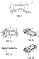
- each flexure element can have a strain responsive element, such as a strain gauge, mounted thereon and configured to respond to the forces acting on the flexure elements of the load cell 1 when a load is applied thereto.
- the load cell 1 comprises up to four apertures 6 (only one shown) in the material of the load cell 1 which are profiled and arranged such that the load cell 1 is capable of resolving and measuring shear forces and bending moments resulting from the application of a load thereto.
- the load cell 1 comprises mounting fixtures (not shown) located at each end thereof for coupling the load cell 1 to a loading fixture 7 and a support structure 8.
- the mounting fixtures provide a mounting surface at each end of the load cell 1 onto which the loading fixture 7 and the support structure 8 may be mounted.
- the mounting surfaces provide a horizontal surface onto which the loading fixture 7 and the support structure 8 may be mounted.
- Attachment fixtures (not shown) in the form of threaded bolts are provided to attach the loading fixture 7 and the support structure 8 to the load cell 1 at the mounting fixtures.
- mounting surfaces are parallel to each other and with each mounting surface located on an opposing surface of the load cell at the opposite end to the mounting surface.
- attachment fixtures distort the end locations and cause output changes that are undetermined and that change with load and temperature and even time and usage.
- the transfer of the mounting distortion in such an arrangement is shown in Figure 1 .
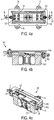
- the symmetrical sensor mounting bracket assembly comprises a first sensor mounting bracket 10a and a second sensor mounting bracket 10b combined together, one above the other in parallel orientation.
- the sensor mounting bracket further comprises a displacement control assembly adapted to limit the deflection of a sensor coupled to the bracket assembly.
- bracket 10 forming part of a sensor mounting bracket assembly according to the first aspect of the present invention is shown.
- the bracket 10 is configured for attachment to a sensor, particularly a load cell.
- bracket 10 comprises a base portion 12 formed of a first base section 12a and a second base section 12b.
- the first base section 12a is frustopyramidal in shape and comprises apertures 14 for receiving fasteners such as bolts or the like.
- the first base section 12a comprises four apertures 14. It would be understood that the first base section 12a may comprise any suitable number of apertures, for example one, two, three, six etc.
- Apertures 14 provide the sensor attachment fixtures of the bracket 10.
- the second base section 12b is formed of an aperture. Upstanding from the edges of base portion 12 are four side walls 16. Side walls 16 have a box-section.
- Mounting elements 18 depend from three of the side walls 16 of bracket 10.
- the mounting elements 18 have a central aperture for receiving attachment fasteners (not shown).
- the attachment fasteners provide an attachment of a support structure and/or a loading fixture to the bracket 10.
- the mounting elements project outwardly from the side walls 16 from which they extend and are arranged such that the bracket is longitudinally symmetrical about a central longitudinal axis 20 of the bracket 10.
- the bracket 10 comprises apertures 22 in the side walls 16 configured to receive coupling elements (not shown).
- the bracket 10 comprises a first aperture 22a having a threaded bore on the side wall 16 without a mounting element 18 and a second aperture 22b on the opposing side wall 16.
- the second aperture 22b may comprise a threaded bore depending on the form of the coupling element utilized for limiting movement between the first and second brackets to each other.
- the bracket 10 further comprises an aperture 24 in the form of a threaded bore in a side wall 16.
- the aperture 24 is located on the same side wall 16 as the second aperture 22b and may be positioned between the second aperture 22b and the mounting element 18 depending from the side wall 16.
- the sensor mounting bracket assembly is formed by combining a first mounting bracket 10a with an identical second mounting bracket 10b.
- the first and second mounting brackets are in accordance with the mounting bracket 10 previously described.
- Displacement control members (not shown) are then inserted into apertures 22 to restrict movement between the brackets 10a, 10b in position relative to one another with a gap between them.
- the second attachment mounting 10b is aligned on top of the first mounting bracket 10a such that the first base section 12a of the second mounting bracket 10b is located in the second base section 12b of the first mounting bracket 10a.
- the first and second brackets 10a, 10b are combined together in parallel relation one above the other in such an assembly.
- Figures 4a to 4c depict a sensor assembly 100 according to an embodiment of the second aspect of the invention.
- First and second sensor mounting brackets 110a, 110b are coupled to a sensor in the form of a load cell 200 in the depicted arrangement.
- Bolts 120 attach the brackets 110a and 110b respectively to the mounting surfaces of sensor 200 through mounting fixtures (not shown).
- the assembly 100 is longitudinally symmetrical about the central longitudinal axis 130 of the assembly. This symmetry improves sensor rejection of output errors due to one or more of: thermal changes, eccentric loading conditions and load cell material characteristics making it more accurate and cost effective.
- the use of identical brackets 110a and 110b reduces cost.
- Three mounting elements with apertures therein in each bracket 110a and 110b provide for more stable support and load effect stress with less dependence on the support and loading attachments to the brackets.
- Decoupling flexible elements are included in the three mounting elements of each bracket 110a and 110b to further reduce mounting stresses.
- the displacement control assembly comprises a first control member 28 and a second control member 30.
- the first control member 28 is in the form of a control member received in an aperture 22 of the first and second mounting brackets 10a, 10b. Due to the arrangement of the first and second mounting brackets 10a, 10b relative to each other, the control member 28 would be received in the second aperture 22b of the first bracket 10a and the first aperture 22a of the second bracket 10b.
- control member 28 is in the form of a threaded flange bolt.
- the thread of the bolt engages with the thread of the second aperture 22b.
- the bolt 28 limits the divergence of the first and second brackets 10a, 10b relative to one another when under a load.
- the bolt 28 can be adjusted to vary the spacing to the first and second brackets 10a, 10b, and hence the permissible divergence when under load.
- the second control member 30 comprises a stopper.
- the stopper 30 is in the form of a threaded cylindrical pin which is received in the threaded aperture 24 in the side wall 16 of the second mounting bracket 10b.
- the stopper 30 is adapted to limit the convergence of the first and second mounting brackets 10a, 10b relative to one other when under load.
- a portion of the stopper 30 in use protrudes from the threaded aperture 24 and convergence of the first and second mounting brackets 10a, 10b towards one another will result in the stopper 30 abutting with the side wall 16 of the first mounting bracket 10a thus limiting further convergence of the brackets 10a, 10b towards one another.
- the amount of permissible convergence will depend on the amount the stopper 30 protrudes from the threaded bore 24.
- the first sensor mounting bracket may be of any suitable footprint for attachment to the required sensor.
- the sensor is of circular footprint
- a first sensor mounting bracket of circular footprint would be suitable for attachment to the sensor.
- a pair of identical sensor mounting brackets are coupled together to form a longitudinally symmetrical sensor mounting bracket assembly according to a first aspect of the invention.
- the symmetrical sensor mounting bracket assembly is coupleable to a symmetrical sensor at its mounting surfaces to provide identical brackets for mounting a sensor with symmetrical provisions for attachment to both a supporting structure and a loading fixture.
- the supporting structure is mounted to the sensor on the same side as the loading fixture mounting.
Landscapes
- Physics & Mathematics (AREA)
- General Physics & Mathematics (AREA)
- Force Measurement Appropriate To Specific Purposes (AREA)
- Connection Of Plates (AREA)
Claims (15)
- Lastsensormontageklammeranordnung, längssymmetrisch um die mittlere Längsachse (130), umfassend eine erste Sensormontageklammer (10a; 110a) und eine zweite Sensormontageklammer (10b; 110b);
zumindest eine Sensorbefestigungsvorrichtung (14; 120), dazu ausgelegt, die Befestigung der ersten Sensormontageklammer oder der zweiten Sensormontageklammer an einer Sensormontagevorrichtung zu erleichtern, und zumindest ein Montageelement (18), dazu ausgelegt, die Befestigung der einen Klammer (10a, 10b; 110a, 110b) an einer Lastaufnahmeplatte oder einer Sensorstützstruktur zu erleichtern,
dadurch gekennzeichnet, dass
die erste Sensormontageklammer (10a, 110a) und die zweite Sensormontageklammer (10b; 110b), eine über der anderen, in paralleler Ausrichtung, miteinander kombiniert werden,
wobei jede der ersten und zweiten Montageklammern (10a, 10b; 110a, 110b) einen Basisteil (12) umfasst, gebildet aus einem ersten Basisabschnitt (12a) und einem zweiten Basisabschnitt (12b), wobei die zweite Montageklammer (10b; 110b) oben auf der ersten Montageklammer (10a; 110a) ausgerichtet ist, sodass der erste Basisabschnitt (12a) der zweiten Montageklammer (10b; 110b) im zweiten Basisabschnitt (12b) der ersten Montageklammer (10a; 110a) befindlich ist. - Montageklammeranordnung nach Anspruch 1, ferner umfassend eine Versetzungssteuerungsanordnung, dazu angepasst, die Durchbiegung eines mit der Klammeranordnung gekoppelten Sensors (100) zu beschränken, wobei die Versetzungssteuerungsanordnung ein erstes Steuerungselement (28) umfasst, das dazu angepasst ist, das Auseinanderlaufen der ersten und zweiten Klammern (10a, 10b; 110a, 110b) relativ zueinander unter Last zu begrenzen,
wobei die ersten und zweiten Klammern (10a, 10b; 110a, 110b) jeweils eine Öffnung (22a, 22b) umfassen, wobei zumindest eine eine gewindete Bohrung zum Aufnehmen des ersten Steuerungselements (28) aufweist. - Montageklammeranordnung nach Anspruch 1 oder 2, wobei die erste Sensormontageklammer (10; 110a) und die zweite Sensormontageklammer (10b; 110b) identisch sind, wobei jede Klammer (10a, 10b; 110a, 110b) einen Basisteil (12a, 12b) und zumindest eine Seitenwand (16), die ausgehend von der Kante des Basisteils aufrecht steht, umfasst, und
wobei die zumindest eine Sensorbefestigungsvorrichtung (14; 120) am Basisteil (12a, 12b) befindlich ist. - Montageklammeranordnung nach einem der vorhergehenden Ansprüche, wobei die Versetzungssteuerungsanordnung ein zweites Steuerungselement (30) umfasst, das dazu angepasst ist, das Zusammenlaufen der ersten und zweiten Klammern (10a, 10b; 110a, 110b) relativ zueinander unter Last zu begrenzen,
wobei das zweite Steuerungselement einen Anschlag umfasst,
wobei der Anschlag in der Form eines gewindeten zylindrischen Stiftes ist,
wobei die ersten und zweiten Klammern (10a, 10b; 110a, 110b) jeweils eine Öffnung (24) umfassen, die eine gewindete Bohrung zum Aufnehmen des zweiten Steuerungselements (30) aufweist. - Montageklammeranordnung nach Anspruch 3 oder 4, wobei der Basisteil (12a, 12b) aus zwei Basisabschnitten gebildet ist,
wobei der erste Basisabschnitt (12a) eine Platte ist und der zweite Basisabschnitt (12b) aus einer Öffnung gebildet ist,
wobei eine Hälfte des Basisteils den ersten Basisabschnitt (12a) bildet und zwischen der quer verlaufenden Mittellinie der ersten Klammer und der Seitenwand (16) an einem Ende der ersten Klammer (10a; 110) befindlich ist und die andere Hälfte des Basisteils den zweiten Basisabschnitt (12b) bildet und zwischen der quer verlaufenden Mittellinie der ersten Klammer (10a; 110a) und der Seitenwand (16) am anderen Ende der ersten Klammer befindlich ist, und
wobei der erste Basisabschnitt unter die Ebene, die die unteren Oberflächen jeder der Seitenwände der ersten Klammer umfasst, eingesenkt ist. - Montageklammeranordnung nach einem der vorhergehenden Ansprüche, wobei die erste Klammer (10a; 110) zumindest eine Sensorbefestigungsvorrichtung (14; 120) umfasst, oder
wobei die erste Klammer (10a; 110a) eine gerade Anzahl an Sensorbefestigungsvorrichtungen (14; 120) umfasst. - Montageklammeranordnung nach Anspruch 6, wobei die Befestigungsvorrichtungen (14; 120) am ersten Basisabschnitt (12a) positioniert sind,
wobei die Befestigungsvorrichtungen (14; 120) am untersten planaren Teil des ersten Basisabschnitts (12a) befindlich sind. - Montageklammeranordnung nach einem der vorhergehenden Ansprüche, wobei die Sensormontageklammeranordnung zumindest ein Montageelement (18) umfasst, das dazu ausgelegt ist, die Befestigung der Klammeranordnung an einer Lastaufnahmeplatte oder einer Sensorstützstruktur zu erleichtern, und/oder wobei die Klammeranordnung mehrere Montageelemente (18) umfasst,
wobei zumindest eins der Montageelemente (18) an der ersten Montageklammer (10a, 110a) befindlich ist, und/oder
wobei zumindest eins der Montageelemente (18) an der zweiten Montageklammer (10b, 110b) befindlich ist. - Montageklammeranordnung nach Anspruch 8, wobei sich das, oder jedes, Montageelement (18) von der, oder jeder, Seitenwand der Klammer (10a, 10b; 110a, 110b) nach außen erstreckt.
- Montageklammeranordnung nach Anspruch 9, wobei die erste Klammer (10a; 110a) drei Montageelemente (18) umfasst, die sich von drei Seitenwänden der ersten Klammer (10a; 110a) nach außen erstrecken.
- Montageklammeranordnung nach Anspruch 10, wobei sich zwei der Montageelemente (18) von einander gegenüberliegenden Seitenwänden (16) nach außen erstrecken und sich das dritte Montageelement (18) von der am Ende der Klammer (10a, 10b; 110a, 110b), angrenzend an den zweiten Basisabschnitt (12b) befindlichen Seitenwand nach außen erstreckt.
- Montageklammeranordnung nach einem der Ansprüche 8 bis 11, wobei die erste Klammer (10a, 110a) längssymmetrisch um eine mittlere Längsachse der ersten Klammer ist.
- Montageklammeranordnung nach einem der Ansprüche 8 bis 12, wobei das, oder jedes, Montageelement (18) eine Öffnung umfasst, und/oder
wobei das, oder jedes, Montageelement (18) ein flexibles Entkopplungselement umfassen kann. - Montageklammeranordnung nach Anspruch 13, wobei das, oder jedes, flexible Entkopplungselement dazu betreibbar ist, Montagebelastungen weiter zu verringern, wenn die erste Klammer (10a, 110a) an einer Lastaufnahmeplatte oder einer Lastzellenstützstruktur montiert ist.
- Lastsensoranordnung, umfassend einen Lastsensor, der symmetrisch um eine mittlere vertikale Achse ist und erste und zweite Montageflächen, jeweils auf der gleichen horizontalen Ebene, umfasst; und eine Montageklammeranordnung nach einem der vorhergehenden Ansprüche.
Applications Claiming Priority (2)
| Application Number | Priority Date | Filing Date | Title |
|---|---|---|---|
| US13/840,891 US9400207B2 (en) | 2013-03-15 | 2013-03-15 | Sensor mounting bracket |
| PCT/US2014/019998 WO2014149635A1 (en) | 2013-03-15 | 2014-03-03 | Improved sensor mounting bracket |
Publications (2)
| Publication Number | Publication Date |
|---|---|
| EP2972141A1 EP2972141A1 (de) | 2016-01-20 |
| EP2972141B1 true EP2972141B1 (de) | 2020-05-06 |
Family
ID=50397259
Family Applications (1)
| Application Number | Title | Priority Date | Filing Date |
|---|---|---|---|
| EP14714455.4A Active EP2972141B1 (de) | 2013-03-15 | 2014-03-03 | Verbesserte sensormontageklammer |
Country Status (4)
| Country | Link |
|---|---|
| US (1) | US9400207B2 (de) |
| EP (1) | EP2972141B1 (de) |
| CA (1) | CA2898119C (de) |
| WO (1) | WO2014149635A1 (de) |
Families Citing this family (4)
| Publication number | Priority date | Publication date | Assignee | Title |
|---|---|---|---|---|
| NL2010270C2 (nl) * | 2013-02-07 | 2014-08-11 | Ravas Europ B V | Hefwagen en heforgaan. |
| US9709436B2 (en) | 2013-03-15 | 2017-07-18 | Illinois Tool Works Inc. | Load cell that is symmetrical about a central vertical axis |
| CN114199358B (zh) * | 2021-12-02 | 2024-11-29 | 安徽天平机械股份有限公司 | 一种稳定性好的称重传感器 |
| CN114909572B (zh) * | 2022-04-18 | 2024-02-02 | 中交二航局建筑科技有限公司 | 可折叠式多角度调节的位移传感器安装设备及其使用方法 |
Family Cites Families (39)
| Publication number | Priority date | Publication date | Assignee | Title |
|---|---|---|---|---|
| US4065962A (en) | 1974-10-29 | 1978-01-03 | Gse, Inc. | Load cell |
| US4143727A (en) | 1977-03-30 | 1979-03-13 | Revere Corporation Of America | Leverless scale sensor |
| US4280576A (en) | 1979-07-09 | 1981-07-28 | Smith Jr James L | Low profile tension mounted load cell industrial scale |
| US4254841A (en) | 1979-10-17 | 1981-03-10 | Maatschappij Van Berkel's Patent N.V. | Load cell overload protection device |
| US4463614A (en) | 1981-05-19 | 1984-08-07 | Setra Systems, Inc. | Force transducer |
| US4438823A (en) | 1982-08-09 | 1984-03-27 | Dbi Industries, Inc. | Load cell |
| US4611677A (en) | 1985-03-07 | 1986-09-16 | National Controls, Inc. | Shock proof scale |
| US4971177A (en) * | 1989-03-24 | 1990-11-20 | Spectra-Physics, Inc. | Data gathering system housing/mounting |
| US4986376A (en) * | 1989-12-01 | 1991-01-22 | Ncr Corporation | Weigh plate quick release mount |
| IT1240002B (it) * | 1990-04-20 | 1993-11-27 | Ramsey Italia | Ponte di pesatura in continuo di materiali solidi trasportati su un nastro convogliatore |
| US5072799A (en) * | 1990-07-11 | 1991-12-17 | Pitney Bowes Inc. | Load cell supporting member and weighing scale incorporating the same |
| SE468023B (sv) * | 1991-02-25 | 1992-10-19 | Asea Brown Boveri | Lastcellshus med inbyggd kraftgivare |
| CH682108A5 (de) * | 1991-04-30 | 1993-07-15 | Mettler Toledo Ag | |
| US5269388A (en) | 1991-11-12 | 1993-12-14 | Stress-Tek, Inc. | Weighing bed |
| US5199518A (en) * | 1992-02-19 | 1993-04-06 | Sheldon Woodle | Load cell |
| US5442146A (en) | 1992-04-03 | 1995-08-15 | Weigh-Tronix, Inc. | Counting scale and load cell assembly therefor |
| CH683717A5 (de) * | 1992-06-09 | 1994-04-29 | Mettler Toledo Ag | Präzisionswaage. |
| US5319161A (en) | 1992-12-24 | 1994-06-07 | Pitney Bowes Inc. | Mechanism for preventing overload on a weighing scale |
| US5419210A (en) | 1993-03-09 | 1995-05-30 | Blh Electronics, Inc. | High capacity weigh module |
| US5600104A (en) * | 1993-10-20 | 1997-02-04 | Structural Instrumentation, Inc. | Load cell having reduced sensitivity to non-symmetrical beam loading |
| US5604336A (en) * | 1995-03-08 | 1997-02-18 | Weigh-Tronix, Inc. | Load cell with composite end beams having portions with different elastic modulus |
| US5747747A (en) * | 1996-01-23 | 1998-05-05 | General Signal Corporation | Continuing belt-type conveyor and means for weighing contents transported thereon |
| FR2796719B1 (fr) | 1999-07-23 | 2001-10-12 | Sidel Sa | Capteur d'effort comportant un dispositif de protection contre les surcharges |
| US6236001B1 (en) * | 1999-08-03 | 2001-05-22 | Wayne W. Shymko | Scoop with weigh scale |
| US6362439B1 (en) * | 2000-04-21 | 2002-03-26 | Stress-Tek, Inc. | Load-cell mounting assembly |
| US6555765B2 (en) * | 2001-06-12 | 2003-04-29 | Alan Paine | Method and apparatus for determining the weight of the contents of a vessel |
| JP2003065834A (ja) * | 2001-08-29 | 2003-03-05 | Shimadzu Corp | 電子天びん |
| US6693244B2 (en) | 2002-01-17 | 2004-02-17 | Weigh-Tronix, Inc. | Method and apparatus for retrofitting an existing conveyor to include a factory calibrated weighing device |
| ATE301827T1 (de) * | 2002-03-18 | 2005-08-15 | Mettler Toledo Gmbh | Kraftaufnehemer, kraftaufnehmer mit einer montagevorrichtung und waage. |
| DE50203820D1 (de) * | 2002-03-18 | 2005-09-08 | Mettler Toledo Gmbh | Modulare Kraftmesszelle für eine Waage und Waage |
| JP3818242B2 (ja) * | 2002-08-26 | 2006-09-06 | 松下電器産業株式会社 | 重量計測装置の取付装置 |
| EP1530035B1 (de) * | 2003-11-06 | 2008-12-31 | Mettler-Toledo AG | Kraftmesszelle mit Befestigungsentkopplung durch vorstehende Flächen und kurze Einschnitte |
| US7373846B2 (en) * | 2004-09-07 | 2008-05-20 | Honda Motor Co., Ltd. | Load cell attachment structure |
| US7040178B1 (en) | 2004-11-19 | 2006-05-09 | Ingersoll Rand Company | Load cell protection apparatus and load detection apparatus incorporating same |
| EP2407342A1 (de) * | 2005-09-30 | 2012-01-18 | TS Tech Co., Ltd. | Vorrichtung zum Messen des Passagiergewichts für Fahrzeugsitz |
| JP2008039585A (ja) * | 2006-08-07 | 2008-02-21 | Denso Corp | センサ装置の取付構造 |
| US7694589B2 (en) | 2007-12-12 | 2010-04-13 | Ecolab Inc. | Low and empty product detection using load cell and load cell bracket |
| CN202676329U (zh) * | 2012-07-04 | 2013-01-16 | 永运电子有限公司 | 一种压力传感器 |
| US9534732B2 (en) * | 2013-03-15 | 2017-01-03 | Illinois Tool Works Inc. | Sensor mounting bracket |
-
2013
- 2013-03-15 US US13/840,891 patent/US9400207B2/en active Active
-
2014
- 2014-03-03 CA CA2898119A patent/CA2898119C/en active Active
- 2014-03-03 EP EP14714455.4A patent/EP2972141B1/de active Active
- 2014-03-03 WO PCT/US2014/019998 patent/WO2014149635A1/en not_active Ceased
Non-Patent Citations (1)
| Title |
|---|
| None * |
Also Published As
| Publication number | Publication date |
|---|---|
| US20140262556A1 (en) | 2014-09-18 |
| US9400207B2 (en) | 2016-07-26 |
| CA2898119C (en) | 2017-12-19 |
| WO2014149635A1 (en) | 2014-09-25 |
| CA2898119A1 (en) | 2014-09-25 |
| EP2972141A1 (de) | 2016-01-20 |
Similar Documents
| Publication | Publication Date | Title |
|---|---|---|
| US9709436B2 (en) | Load cell that is symmetrical about a central vertical axis | |
| CA2898118C (en) | Improved sensor mounting bracket | |
| US7429705B2 (en) | Parallel-guiding mechanism for compact weighing system | |
| US9032817B2 (en) | Low profile load transducer | |
| CN100395523C (zh) | 力传感器的安装装置以及称量秤 | |
| EP2972141B1 (de) | Verbesserte sensormontageklammer | |
| US20140345955A1 (en) | Sensor package for wim sensor and wim sensor | |
| US5056361A (en) | Dual strain gage balance system for measuring light loads | |
| GB2117128A (en) | Load cells | |
| CN110849450B (zh) | 称重传感器及包括其的称重秤 | |
| US5090493A (en) | Load cells and scales therefrom | |
| US4506746A (en) | Gaged plate transducer weighing apparatus | |
| US9791332B2 (en) | Rod-shaped force transducer with improved deformation behavior | |
| JP7064626B2 (ja) | トライペダルフレクシャ部材及びそれを用いた負荷/トルク測定システム | |
| US20160161348A1 (en) | Rod-Shaped Force Transducer With Simplified Adjustment | |
| EP1043573B1 (de) | Scherkraftlastzelle | |
| US7318358B2 (en) | Strain sensor that compensates for thermal strain | |
| US10830271B2 (en) | Sensor for measuring a tightening force applied on a screw-assembly member | |
| KR100317841B1 (ko) | 전자저울용로드셀및플랫폼 | |
| US10718656B2 (en) | Suspension for a weighing cell |
Legal Events
| Date | Code | Title | Description |
|---|---|---|---|
| PUAI | Public reference made under article 153(3) epc to a published international application that has entered the european phase |
Free format text: ORIGINAL CODE: 0009012 |
|
| 17P | Request for examination filed |
Effective date: 20150716 |
|
| AK | Designated contracting states |
Kind code of ref document: A1 Designated state(s): AL AT BE BG CH CY CZ DE DK EE ES FI FR GB GR HR HU IE IS IT LI LT LU LV MC MK MT NL NO PL PT RO RS SE SI SK SM TR |
|
| AX | Request for extension of the european patent |
Extension state: BA ME |
|
| DAX | Request for extension of the european patent (deleted) | ||
| STAA | Information on the status of an ep patent application or granted ep patent |
Free format text: STATUS: EXAMINATION IS IN PROGRESS |
|
| 17Q | First examination report despatched |
Effective date: 20171208 |
|
| GRAP | Despatch of communication of intention to grant a patent |
Free format text: ORIGINAL CODE: EPIDOSNIGR1 |
|
| STAA | Information on the status of an ep patent application or granted ep patent |
Free format text: STATUS: GRANT OF PATENT IS INTENDED |
|
| INTG | Intention to grant announced |
Effective date: 20190927 |
|
| GRAS | Grant fee paid |
Free format text: ORIGINAL CODE: EPIDOSNIGR3 |
|
| GRAA | (expected) grant |
Free format text: ORIGINAL CODE: 0009210 |
|
| STAA | Information on the status of an ep patent application or granted ep patent |
Free format text: STATUS: THE PATENT HAS BEEN GRANTED |
|
| AK | Designated contracting states |
Kind code of ref document: B1 Designated state(s): AL AT BE BG CH CY CZ DE DK EE ES FI FR GB GR HR HU IE IS IT LI LT LU LV MC MK MT NL NO PL PT RO RS SE SI SK SM TR |
|
| REG | Reference to a national code |
Ref country code: GB Ref legal event code: FG4D |
|
| REG | Reference to a national code |
Ref country code: CH Ref legal event code: EP Ref country code: AT Ref legal event code: REF Ref document number: 1267521 Country of ref document: AT Kind code of ref document: T Effective date: 20200515 |
|
| REG | Reference to a national code |
Ref country code: DE Ref legal event code: R096 Ref document number: 602014064898 Country of ref document: DE |
|
| REG | Reference to a national code |
Ref country code: IE Ref legal event code: FG4D |
|
| REG | Reference to a national code |
Ref country code: NL Ref legal event code: FP |
|
| REG | Reference to a national code |
Ref country code: LT Ref legal event code: MG4D |
|
| PG25 | Lapsed in a contracting state [announced via postgrant information from national office to epo] |
Ref country code: PT Free format text: LAPSE BECAUSE OF FAILURE TO SUBMIT A TRANSLATION OF THE DESCRIPTION OR TO PAY THE FEE WITHIN THE PRESCRIBED TIME-LIMIT Effective date: 20200907 Ref country code: IS Free format text: LAPSE BECAUSE OF FAILURE TO SUBMIT A TRANSLATION OF THE DESCRIPTION OR TO PAY THE FEE WITHIN THE PRESCRIBED TIME-LIMIT Effective date: 20200906 Ref country code: FI Free format text: LAPSE BECAUSE OF FAILURE TO SUBMIT A TRANSLATION OF THE DESCRIPTION OR TO PAY THE FEE WITHIN THE PRESCRIBED TIME-LIMIT Effective date: 20200506 Ref country code: SE Free format text: LAPSE BECAUSE OF FAILURE TO SUBMIT A TRANSLATION OF THE DESCRIPTION OR TO PAY THE FEE WITHIN THE PRESCRIBED TIME-LIMIT Effective date: 20200506 Ref country code: LT Free format text: LAPSE BECAUSE OF FAILURE TO SUBMIT A TRANSLATION OF THE DESCRIPTION OR TO PAY THE FEE WITHIN THE PRESCRIBED TIME-LIMIT Effective date: 20200506 Ref country code: NO Free format text: LAPSE BECAUSE OF FAILURE TO SUBMIT A TRANSLATION OF THE DESCRIPTION OR TO PAY THE FEE WITHIN THE PRESCRIBED TIME-LIMIT Effective date: 20200806 Ref country code: GR Free format text: LAPSE BECAUSE OF FAILURE TO SUBMIT A TRANSLATION OF THE DESCRIPTION OR TO PAY THE FEE WITHIN THE PRESCRIBED TIME-LIMIT Effective date: 20200807 |
|
| PG25 | Lapsed in a contracting state [announced via postgrant information from national office to epo] |
Ref country code: BG Free format text: LAPSE BECAUSE OF FAILURE TO SUBMIT A TRANSLATION OF THE DESCRIPTION OR TO PAY THE FEE WITHIN THE PRESCRIBED TIME-LIMIT Effective date: 20200806 Ref country code: RS Free format text: LAPSE BECAUSE OF FAILURE TO SUBMIT A TRANSLATION OF THE DESCRIPTION OR TO PAY THE FEE WITHIN THE PRESCRIBED TIME-LIMIT Effective date: 20200506 Ref country code: LV Free format text: LAPSE BECAUSE OF FAILURE TO SUBMIT A TRANSLATION OF THE DESCRIPTION OR TO PAY THE FEE WITHIN THE PRESCRIBED TIME-LIMIT Effective date: 20200506 Ref country code: HR Free format text: LAPSE BECAUSE OF FAILURE TO SUBMIT A TRANSLATION OF THE DESCRIPTION OR TO PAY THE FEE WITHIN THE PRESCRIBED TIME-LIMIT Effective date: 20200506 |
|
| REG | Reference to a national code |
Ref country code: AT Ref legal event code: MK05 Ref document number: 1267521 Country of ref document: AT Kind code of ref document: T Effective date: 20200506 |
|
| PG25 | Lapsed in a contracting state [announced via postgrant information from national office to epo] |
Ref country code: AL Free format text: LAPSE BECAUSE OF FAILURE TO SUBMIT A TRANSLATION OF THE DESCRIPTION OR TO PAY THE FEE WITHIN THE PRESCRIBED TIME-LIMIT Effective date: 20200506 |
|
| PG25 | Lapsed in a contracting state [announced via postgrant information from national office to epo] |
Ref country code: AT Free format text: LAPSE BECAUSE OF FAILURE TO SUBMIT A TRANSLATION OF THE DESCRIPTION OR TO PAY THE FEE WITHIN THE PRESCRIBED TIME-LIMIT Effective date: 20200506 Ref country code: DK Free format text: LAPSE BECAUSE OF FAILURE TO SUBMIT A TRANSLATION OF THE DESCRIPTION OR TO PAY THE FEE WITHIN THE PRESCRIBED TIME-LIMIT Effective date: 20200506 Ref country code: ES Free format text: LAPSE BECAUSE OF FAILURE TO SUBMIT A TRANSLATION OF THE DESCRIPTION OR TO PAY THE FEE WITHIN THE PRESCRIBED TIME-LIMIT Effective date: 20200506 Ref country code: SM Free format text: LAPSE BECAUSE OF FAILURE TO SUBMIT A TRANSLATION OF THE DESCRIPTION OR TO PAY THE FEE WITHIN THE PRESCRIBED TIME-LIMIT Effective date: 20200506 Ref country code: EE Free format text: LAPSE BECAUSE OF FAILURE TO SUBMIT A TRANSLATION OF THE DESCRIPTION OR TO PAY THE FEE WITHIN THE PRESCRIBED TIME-LIMIT Effective date: 20200506 Ref country code: IT Free format text: LAPSE BECAUSE OF FAILURE TO SUBMIT A TRANSLATION OF THE DESCRIPTION OR TO PAY THE FEE WITHIN THE PRESCRIBED TIME-LIMIT Effective date: 20200506 Ref country code: CZ Free format text: LAPSE BECAUSE OF FAILURE TO SUBMIT A TRANSLATION OF THE DESCRIPTION OR TO PAY THE FEE WITHIN THE PRESCRIBED TIME-LIMIT Effective date: 20200506 Ref country code: RO Free format text: LAPSE BECAUSE OF FAILURE TO SUBMIT A TRANSLATION OF THE DESCRIPTION OR TO PAY THE FEE WITHIN THE PRESCRIBED TIME-LIMIT Effective date: 20200506 |
|
| REG | Reference to a national code |
Ref country code: DE Ref legal event code: R097 Ref document number: 602014064898 Country of ref document: DE |
|
| PG25 | Lapsed in a contracting state [announced via postgrant information from national office to epo] |
Ref country code: PL Free format text: LAPSE BECAUSE OF FAILURE TO SUBMIT A TRANSLATION OF THE DESCRIPTION OR TO PAY THE FEE WITHIN THE PRESCRIBED TIME-LIMIT Effective date: 20200506 Ref country code: SK Free format text: LAPSE BECAUSE OF FAILURE TO SUBMIT A TRANSLATION OF THE DESCRIPTION OR TO PAY THE FEE WITHIN THE PRESCRIBED TIME-LIMIT Effective date: 20200506 |
|
| PLBE | No opposition filed within time limit |
Free format text: ORIGINAL CODE: 0009261 |
|
| STAA | Information on the status of an ep patent application or granted ep patent |
Free format text: STATUS: NO OPPOSITION FILED WITHIN TIME LIMIT |
|
| 26N | No opposition filed |
Effective date: 20210209 |
|
| PG25 | Lapsed in a contracting state [announced via postgrant information from national office to epo] |
Ref country code: SI Free format text: LAPSE BECAUSE OF FAILURE TO SUBMIT A TRANSLATION OF THE DESCRIPTION OR TO PAY THE FEE WITHIN THE PRESCRIBED TIME-LIMIT Effective date: 20200506 |
|
| PG25 | Lapsed in a contracting state [announced via postgrant information from national office to epo] |
Ref country code: MC Free format text: LAPSE BECAUSE OF FAILURE TO SUBMIT A TRANSLATION OF THE DESCRIPTION OR TO PAY THE FEE WITHIN THE PRESCRIBED TIME-LIMIT Effective date: 20200506 |
|
| REG | Reference to a national code |
Ref country code: CH Ref legal event code: PL |
|
| REG | Reference to a national code |
Ref country code: BE Ref legal event code: MM Effective date: 20210331 |
|
| PG25 | Lapsed in a contracting state [announced via postgrant information from national office to epo] |
Ref country code: LI Free format text: LAPSE BECAUSE OF NON-PAYMENT OF DUE FEES Effective date: 20210331 Ref country code: LU Free format text: LAPSE BECAUSE OF NON-PAYMENT OF DUE FEES Effective date: 20210303 Ref country code: CH Free format text: LAPSE BECAUSE OF NON-PAYMENT OF DUE FEES Effective date: 20210331 |
|
| PG25 | Lapsed in a contracting state [announced via postgrant information from national office to epo] |
Ref country code: BE Free format text: LAPSE BECAUSE OF NON-PAYMENT OF DUE FEES Effective date: 20210331 |
|
| PG25 | Lapsed in a contracting state [announced via postgrant information from national office to epo] |
Ref country code: HU Free format text: LAPSE BECAUSE OF FAILURE TO SUBMIT A TRANSLATION OF THE DESCRIPTION OR TO PAY THE FEE WITHIN THE PRESCRIBED TIME-LIMIT; INVALID AB INITIO Effective date: 20140303 |
|
| PG25 | Lapsed in a contracting state [announced via postgrant information from national office to epo] |
Ref country code: CY Free format text: LAPSE BECAUSE OF FAILURE TO SUBMIT A TRANSLATION OF THE DESCRIPTION OR TO PAY THE FEE WITHIN THE PRESCRIBED TIME-LIMIT Effective date: 20200506 |
|
| P01 | Opt-out of the competence of the unified patent court (upc) registered |
Effective date: 20230606 |
|
| PG25 | Lapsed in a contracting state [announced via postgrant information from national office to epo] |
Ref country code: MK Free format text: LAPSE BECAUSE OF FAILURE TO SUBMIT A TRANSLATION OF THE DESCRIPTION OR TO PAY THE FEE WITHIN THE PRESCRIBED TIME-LIMIT Effective date: 20200506 |
|
| PG25 | Lapsed in a contracting state [announced via postgrant information from national office to epo] |
Ref country code: TR Free format text: LAPSE BECAUSE OF FAILURE TO SUBMIT A TRANSLATION OF THE DESCRIPTION OR TO PAY THE FEE WITHIN THE PRESCRIBED TIME-LIMIT Effective date: 20200506 |
|
| PG25 | Lapsed in a contracting state [announced via postgrant information from national office to epo] |
Ref country code: MT Free format text: LAPSE BECAUSE OF FAILURE TO SUBMIT A TRANSLATION OF THE DESCRIPTION OR TO PAY THE FEE WITHIN THE PRESCRIBED TIME-LIMIT Effective date: 20200506 |
|
| PGFP | Annual fee paid to national office [announced via postgrant information from national office to epo] |
Ref country code: GB Payment date: 20260327 Year of fee payment: 13 |
|
| PGFP | Annual fee paid to national office [announced via postgrant information from national office to epo] |
Ref country code: DE Payment date: 20260327 Year of fee payment: 13 Ref country code: IE Payment date: 20260327 Year of fee payment: 13 |
|
| PGFP | Annual fee paid to national office [announced via postgrant information from national office to epo] |
Ref country code: NL Payment date: 20260326 Year of fee payment: 13 |
|
| PGFP | Annual fee paid to national office [announced via postgrant information from national office to epo] |
Ref country code: FR Payment date: 20260325 Year of fee payment: 13 |