EP2969866B1 - Umlenkender förderer mit magnetischen antriebsaggregaten - Google Patents
Umlenkender förderer mit magnetischen antriebsaggregaten Download PDFInfo
- Publication number
- EP2969866B1 EP2969866B1 EP14773966.8A EP14773966A EP2969866B1 EP 2969866 B1 EP2969866 B1 EP 2969866B1 EP 14773966 A EP14773966 A EP 14773966A EP 2969866 B1 EP2969866 B1 EP 2969866B1
- Authority
- EP
- European Patent Office
- Prior art keywords
- movers
- conveyor
- magnetic field
- conveyor belt
- metallic elements
- Prior art date
- Legal status (The legal status is an assumption and is not a legal conclusion. Google has not performed a legal analysis and makes no representation as to the accuracy of the status listed.)
- Active
Links
- 230000005291 magnetic effect Effects 0.000 claims description 36
- 229910052751 metal Inorganic materials 0.000 claims description 23
- 230000000717 retained effect Effects 0.000 claims description 5
- 239000003302 ferromagnetic material Substances 0.000 claims description 4
- 238000000034 method Methods 0.000 claims description 4
- 230000006698 induction Effects 0.000 claims description 3
- 239000002184 metal Substances 0.000 claims description 3
- 230000001360 synchronised effect Effects 0.000 claims description 3
- 239000011230 binding agent Substances 0.000 claims description 2
- 239000004020 conductor Substances 0.000 claims description 2
- 230000008878 coupling Effects 0.000 claims description 2
- 238000010168 coupling process Methods 0.000 claims description 2
- 238000005859 coupling reaction Methods 0.000 claims description 2
- 238000003491 array Methods 0.000 claims 1
- 230000005294 ferromagnetic effect Effects 0.000 description 2
- 239000007769 metal material Substances 0.000 description 2
- 230000003670 easy-to-clean Effects 0.000 description 1
- 230000005672 electromagnetic field Effects 0.000 description 1
- 230000003993 interaction Effects 0.000 description 1
- 230000000630 rising effect Effects 0.000 description 1
- 230000032258 transport Effects 0.000 description 1
Images

Classifications
-
- B—PERFORMING OPERATIONS; TRANSPORTING
- B65—CONVEYING; PACKING; STORING; HANDLING THIN OR FILAMENTARY MATERIAL
- B65G—TRANSPORT OR STORAGE DEVICES, e.g. CONVEYORS FOR LOADING OR TIPPING, SHOP CONVEYOR SYSTEMS OR PNEUMATIC TUBE CONVEYORS
- B65G47/00—Article or material-handling devices associated with conveyors; Methods employing such devices
- B65G47/74—Feeding, transfer, or discharging devices of particular kinds or types
- B65G47/84—Star-shaped wheels or devices having endless travelling belts or chains, the wheels or devices being equipped with article-engaging elements
- B65G47/841—Devices having endless travelling belts or chains equipped with article-engaging elements
- B65G47/844—Devices having endless travelling belts or chains equipped with article-engaging elements the article-engaging elements being pushers transversally movable on the supporting surface, e.g. pusher-shoes
-
- B—PERFORMING OPERATIONS; TRANSPORTING
- B65—CONVEYING; PACKING; STORING; HANDLING THIN OR FILAMENTARY MATERIAL
- B65G—TRANSPORT OR STORAGE DEVICES, e.g. CONVEYORS FOR LOADING OR TIPPING, SHOP CONVEYOR SYSTEMS OR PNEUMATIC TUBE CONVEYORS
- B65G17/00—Conveyors having an endless traction element, e.g. a chain, transmitting movement to a continuous or substantially-continuous load-carrying surface or to a series of individual load-carriers; Endless-chain conveyors in which the chains form the load-carrying surface
- B65G17/06—Conveyors having an endless traction element, e.g. a chain, transmitting movement to a continuous or substantially-continuous load-carrying surface or to a series of individual load-carriers; Endless-chain conveyors in which the chains form the load-carrying surface having a load-carrying surface formed by a series of interconnected, e.g. longitudinal, links, plates, or platforms
- B65G17/08—Conveyors having an endless traction element, e.g. a chain, transmitting movement to a continuous or substantially-continuous load-carrying surface or to a series of individual load-carriers; Endless-chain conveyors in which the chains form the load-carrying surface having a load-carrying surface formed by a series of interconnected, e.g. longitudinal, links, plates, or platforms the surface being formed by the traction element
-
- B—PERFORMING OPERATIONS; TRANSPORTING
- B65—CONVEYING; PACKING; STORING; HANDLING THIN OR FILAMENTARY MATERIAL
- B65G—TRANSPORT OR STORAGE DEVICES, e.g. CONVEYORS FOR LOADING OR TIPPING, SHOP CONVEYOR SYSTEMS OR PNEUMATIC TUBE CONVEYORS
- B65G17/00—Conveyors having an endless traction element, e.g. a chain, transmitting movement to a continuous or substantially-continuous load-carrying surface or to a series of individual load-carriers; Endless-chain conveyors in which the chains form the load-carrying surface
- B65G17/30—Details; Auxiliary devices
- B65G17/32—Individual load-carriers
- B65G17/34—Individual load-carriers having flat surfaces, e.g. platforms, grids, forks
- B65G17/345—Individual load-carriers having flat surfaces, e.g. platforms, grids, forks the surfaces being equipped with a conveyor
-
- B—PERFORMING OPERATIONS; TRANSPORTING
- B65—CONVEYING; PACKING; STORING; HANDLING THIN OR FILAMENTARY MATERIAL
- B65G—TRANSPORT OR STORAGE DEVICES, e.g. CONVEYORS FOR LOADING OR TIPPING, SHOP CONVEYOR SYSTEMS OR PNEUMATIC TUBE CONVEYORS
- B65G47/00—Article or material-handling devices associated with conveyors; Methods employing such devices
- B65G47/34—Devices for discharging articles or materials from conveyor
Definitions
- the invention relates generally to power-driven conveyors and more particularly to shoe-type diverting conveyors.
- Diverting conveyors such as shoe sorters, are used to divert articles across the width of a conveyor as the conveyor transports the articles in a conveying direction.
- Typical shoe sorters include article-pushing elements referred to as shoes that are driven laterally across the conveyor to push articles off one or both sides of the conveyor to one or more outfeed locations.
- Slat conveyors and modular conveyor belts are used as the platform for the shoes, which ride in tracks extending across the widths of the slats or belt modules.
- the shoes are conventionally blocked-shaped with depending structural elements that keep the shoe in the track and serve as cam followers that extend below to be guided by carryway guides that control the lateral positions of shoes.
- One version of a conveyor embodying features of the invention comprises a modular conveyor belt and a magnetic field source.
- the conveyor belt has tracks that extend across the conveyor belt transverse to the direction of belt travel.
- Movers are retained in the tracks to move along the tracks across the belt.
- the movers have contact faces that engage articles conveyed on the belt.
- the magnetic field source provides a magnetic field that interacts with the movers to propel the movers along the tracks and conveyed articles engaged by the contact faces across the conveyor belt.
- a method for moving articles across the conveying surface of the modular conveyor belt of the conveyor comprises: (a) creating a magnetic field that varies spatially or temporally across the width of a conveyor; (b) coupling the magnetic field to movers mounted in the conveyor to propel the movers across the width of the conveyor with the varying magnetic field; and (c) engaging articles on the conveying surface of the conveyor with the movers to move the articles across the width of the conveying surface.
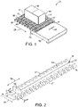
- the conveyor 20 comprises a conveyor belt 22 that advances in a direction of belt travel 24.
- the belt may be driven by any conventional drive means (not shown), such as motor-driven drums, pulleys, or sprockets, or by a linear induction motor.
- the conveyor belt is a modular plastic conveyor belt constructed of a series of belt modules 26 arranged in rows linked together at hinge joints 28.
- the conveyor belt 22 extends in width from a first outside edge 30 to an opposite second outside edge 31.
- a shoe more generically, a mover 34
- the mover is able to slide along the track in both directions 36.
- Hinge elements 37 at opposite ends of each module are interleaved with the hinge elements of adjacent modules and linked by hinge pins 39 to form the hinge joints 28 between adjacent rows.
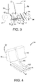
- a magnetic field source 38 positioned under the upper carryway path of the conveyor belt 22 produces a magnetic or electromagnetic field that varies spatially or temporally across the width of the conveyor in either direction, as indicated by two-headed arrow 40 in FIG. 1 .
- the varying magnetic field interacts with metallic material in the movers 34 to propel the movers across the width of the belt without the contact present in cam-guided diverters.
- the movers divert articles 42 conveyed atop the belt's top conveying surface 44 across the belt to a selected lateral position or completely off the side of the belt.
- Magnetic field sources may be installed at selected positions along the length of the conveyor to provide additional divert zones or mover-return zones.
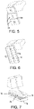
- the mover has a pusher portion 46 above the top conveying surface 44 of the belt.
- the pusher 46 has a contact face 48, which is shown as a curved surface in this example.
- the opposite side of the pusher has a flat surface 50.
- the pusher portion 46 is connected to a base 52 by an intermediate shank 54.
- the base 52 is retained in and rides transversely across the width of the belt module 26 in a slot 56 shaped like an inverted T.
- the base in this example serves as a skid 52 that rides in the base 58 of the inverted-T slot.
- the narrow shank 54 extends upward from the skid through the vertical branch of the inverted-T slot, which opens onto the top conveying surface 44 and forms the lateral track 32.
- the mover could have a support plate with a flat horizontal upper contact surface engaging the bottoms of conveyed articles to divert the articles sitting on the contact face of the mover.
- the skid 52 includes ferromagnetic or electrically conductive metallic elements.
- the elements can be in the form of metal plates 64 housed in the skids or can be a metallic material combined with a plastic binder and molded to form the skid.
- the metal plate 64 could also be made of a ferromagnetic material layered atop an electrically conductive material for increased force.
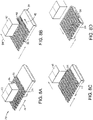
- the metallic elements can be permanent magnets 66 housed within or attached to the base 68 as in FIG. 5 .
- Permanent magnets 70 can be arranged with the base 68 in a Halbach array 72 as shown in FIG. 6 to focus their magnetic field toward the bottom of the conveyor belt and the magnetic field source. And, in the example shown in FIG.
- the metallic element can be in the form of a ferromagnetic linear rotor, or forcer 74, having a series of teeth 76 forming poles.
- the magnetic field generator 38 used in the conveyor 20 of FIG. 1 comprises a stator 78 having poles 80 matching the teeth 76 to form a linear variable reluctance motor or a linear stepper motor with the rotor 74.
- the movers of FIGS. 5 and 6 whose metallic elements are permanent magnets, are driven transversely across the conveyor belt by the magnetic field source, which has a linear stator that is energized to produce a traveling magnetic field that interacts with the magnets.
- the linear stator may be operated with a permanent-magnet forcer as a synchronous ac motor or a brushless dc motor.
- the magnetic field generator has a linear stator that produces a traveling magnetic field that induces a current in the electrically conductive metallic elements.
- the induced current produces a magnetic field in the mover that interacts with the traveling magnetic field to produce a force that propels the mover along the track.
- the magnetic field generator's stator and the mover's electrically-conductive forcer form a linear induction motor.
- FIGS. 8A-8D The operation of the conveyor 20 as a sorter is illustrated in FIGS. 8A-8D .
- FIG. 8A an article 42 is shown being conveyed by the conveyor belt 22 in a direction of belt travel 24. All the movers are shown in their reset positions at one side of the belt.
- FIG. 8B the magnetic field source 38 is activated to produce a magnetic field that intersects the conveyor and varies across the conveyor in the direction of arrow 82.
- the interaction of the magnetic field with the metallic elements in the movers 34 produces a force that propels the movers along their transverse tracks 32.
- the contact faces 48 of the movers engage the article 42 and push it across the top conveying surface 26 of the conveyor belt 22 in the direction of arrow 84.
- FIG. 8A an article 42 is shown being conveyed by the conveyor belt 22 in a direction of belt travel 24. All the movers are shown in their reset positions at one side of the belt.
- FIG. 8B the magnetic field source 38 is activated to produce a magnetic field
- the article 42 is shown pushed off the side of the conveyor belt 22 by the movers 34.
- the magnetic field source 38 generates a magnetic field that varies in the opposite direction 86 to return the movers 34 to their reset position at the opposite side of the belt.
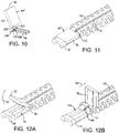
- FIGS. 9-12 Another version of a conveyor belt module usable in a conveyor as in FIG. 1 is shown in FIGS. 9-12 .
- the belt module 88 has two movers 90, 91 riding in the same track 92.
- the contact faces 94, 94' of the movers are shown as flat.
- the two faces 94, 94' face each other across the module.
- each mover has an upper pusher 96 connected to a lower base or skid 98 by an intermediate shank 100.
- a pair of guide pins 102 and a pair of pivot pins 104 extend from the sides of the shank 100.
- the shank also includes a tab 106 extending away from the skid 98.
- the pivot pins 104 are received in hinge eyes 108 at one end of the skid 98.
- the resulting hinge joint allows the pusher 96 and the shank 100 to pivot relative to the skid 98, as indicated by the arrows 110, 111 in FIG. 9 .
- the track 92 is formed by an inverted-T-shaped slot as in FIG. 3 , but with a guide slot 112 parallel to the base portion 58 between the base portion and the top conveying surface 113 of the module 88, as best shown in FIGS. 11 and 12B .
- the mover's guide pins 102 are received in the guide slot 112.
- the guide slot 112 has a curved portion 114 that curves downward at each end of the track 92.
- FIG. 11 the mover 90 is shown in its retracted position.
- the flat contact face 94' of the retracted pusher 96 is generally flush with or below the level of the top conveying surface 113 of the belt module.
- the mover 90 is folded down in its retracted position, the other mover 91 can push an article off the side of the belt over the retracted mover 90 along the flat face 94' of the pusher 96.
- FIGS. 12A and 12B illustrate the mover's pusher 96 rising to an extended position for pushing articles across the belt.
Claims (15)
- Förderband (20), umfassend:
Ein modulares Förderband (22; 88), das einschließt:Eine Vielzahl von Bahnen (32; 92), die sich über die Breite des modularen Förderbands (22; 88) quer zur Bandlaufrichtung (24) erstrecken;eine Vielzahl von Antriebsaggregaten (34; 90, 91), die in den Bahnen (32; 02) beibehalten sind, um sich entlang der Bahnen (32; 92) quer über das modulare Förderband (22; 88) zu bewegen, wobei die Antriebsaggregate (34; 90,91) Kontaktflächen (48; 94, 94') in Eingriff mit beförderten Artikeln (42) gebracht werden, gekennzeichnet durcheine Magnetfeldquelle (38) die ein Magnetfeld bereitstellt, das mit den Antriebsaggregaten (34; 90, 91) interagiert, um die Antriebsaggregate (34; 90, 91) entlang der Bahnen (32; 92) quer über die Breite des modularen Förderbands (22; 88) und die beförderten Artikel (42), die mit den Kontaktflächen (48; 94, 94') in Eingriff sind, quer über das modulare Förderband (22; 88) anzutreiben. - Förderer nach Anspruch 1, wobei die Antriebsaggregate (34; 90, 91) metallische Elemente einschließen, die elektrisch leitend sind und die Magnetfeldquelle einen Stator einschließt, der einen Induktionslinearmotor bildet, wobei die metallischen Elemente als vom Stator angetriebene "Forcer" arbeiten oder wobei die Antriebsaggregate metallische Elemente einschließen, die Permanentmagnete (66) sind und die Magnetfeldquelle einen Stator einschließt, der einen Synchron-Linearmotor bildet, wobei die metallischen Elemente als vom Stator angetriebene Forcer arbeiten.
- Förderer nach Anspruch 1, wobei die Antriebsaggregate metallische Elemente einschließen, die in Halbach-Arrays (72) angeordnete Permanentmagnete (70) sind und die Magnetfeldquelle einen Stator einschließt, der einen Synchron-Linearmotor oder einen bürstenlosen Gleichstrommotor bildet, wobei die metallischen Elemente als vom Stator angetriebene Forcer arbeiten.
- Förderer nach Anspruch 1, wobei die Antriebsaggregate metallische Elemente einschließt, die aus einem ferromagnetischen Material kombiniert mit einem Kunststoffbinder hergestellt sind, um zumindest einen Teil des Antriebsaggregates zu bilden.
- Förderer nach Anspruch 1, wobei die Antriebsaggregate metallische Elemente einschließen, die aus einem ferromagnetischen Material auf einem elektrisch leitenden Material hergestellt sind.
- Förderer nach Anspruch 1, wobei die Antriebsaggregate metallische Elemente einschließen, die aus einem ferromagnetischen Material hergestellt sind und eine Reihe von Zähnen aufweisen und, wobei die Magnetfeldquelle einen Stator mit Polen aufweist, die zu den Zähnen passen, um mit den metallischen Elementen Motoren zu bilden.
- Förderer nach Anspruch 1, wobei die Antriebsaggregate (90, 91) Metallplatten einschließen.
- Förderer nach Anspruch 1, wobei das Förderband (22) eine obere Förderfläche (44) einschließt und, wobei die Bahnen (32) Querschlitze (56) innerhalb des Förderbands (22) umfassen, die sich zur oberen Förderfläche (44) hin öffnen und, wobei die Antriebsaggregate (34) metallische Elemente einschließen, die in den Schlitzen (56) liegen und, wobei die Kontaktflächen (48) an oder über der oberen Förderfläche (44) liegen.
- Förderer nach Anspruch 8, wobei die Schlitze (56) eine invertierte T-Form aufweisen und die Antriebsaggregate (34) metallische Elemente enthaltende Basen (52) einschließen und die Antriebsaggregate (34) zwischen den Basen (52) und den Kontaktflächen (48) verbundene Schäfte (54) einschließen und, wobei die Basen (52) verschiebbar in den Schlitzen (56) mit invertierter T-Form beibehalten sind.
- Förderer nach Anspruch 1, wobei die Antriebsaggregate metallische Elemente einschließen, die unterhalb der Kontaktflächen angeordnet sind und, wobei die Magnetfeldquelle unterhalb und nahe dem Förderband über einem Spalt angeordnet ist.
- Förderer nach Anspruch 1, wobei das Förderband (88) eine obere Förderfläche einschließt und, wobei die Antriebsaggregate (90, 91) Schieber einschließen, auf denen die Kontaktflächen (94, 94') gebildet sind, um beförderte Artikel in einer ausgefahrenen Position der Antriebsaggregate über die obere Förderfläche zu schieben und, wobei Scharniere an den Antriebsaggregaten den Schiebern erlauben, sich in der eingefahrenen Position auf eine Höhe mit oder unterhalb der oberen Förderfläche herunterzuklappen.
- Förderer nach Anspruch 11, wobei Kontaktflächen bündig mit oder unterhalb der Höhe der oberen Förderfläche sind, wenn sich die Schieber in der eingefahrenen Position befinden.
- Förderer nach Anspruch 11, der zwei Antriebsaggregate in jeder Bahn umfasst und, wobei jeder Schieber an einem jeweiligen Außenrand des Förderbands herunterklappt, um dem anderen Schieber zu ermöglichen, beförderte Artikel vom Seitenrand über den heruntergeklappten Schieber zu schieben.
- Verfahren zum Bewegen von Artikeln quer über die Förderfläche eines modularen Förderbands (22; 88) in einem Förderer (20) nach einem beliebigen der Ansprüche 1 bis 13, wobei das Verfahren umfasst: Schaffung eines Magnetfelds, das räumlich und zeitlich über die Breite des Förderbands variiert;Koppeln des Magnetfelds mit den im Förderband montierten Antriebsaggregaten, um die Antriebsaggregate über die Breite des Förderers mit dem variierenden Magnetfeld anzutreiben;in Eingriff bringen von Artikeln auf einer Förderfläche des Förderbands mit den Antriebsaggregaten, um die Artikel über die Breite der Förderfläche zu bewegen.
- Verfahren nach Anspruch 14, das ferner das Senken der Antriebsaggregate auf eine Höhe mit oder unterhalb der Höhe der Förderfläche an einem Außenrand des Förderers umfasst.
Applications Claiming Priority (2)
| Application Number | Priority Date | Filing Date | Title |
|---|---|---|---|
| US201361781567P | 2013-03-14 | 2013-03-14 | |
| PCT/US2014/022998 WO2014159317A1 (en) | 2013-03-14 | 2014-03-11 | Diverting conveyor with magnetically driven movers |
Publications (3)
| Publication Number | Publication Date |
|---|---|
| EP2969866A1 EP2969866A1 (de) | 2016-01-20 |
| EP2969866A4 EP2969866A4 (de) | 2016-09-28 |
| EP2969866B1 true EP2969866B1 (de) | 2022-04-27 |
Family
ID=51625145
Family Applications (1)
| Application Number | Title | Priority Date | Filing Date |
|---|---|---|---|
| EP14773966.8A Active EP2969866B1 (de) | 2013-03-14 | 2014-03-11 | Umlenkender förderer mit magnetischen antriebsaggregaten |
Country Status (5)
| Country | Link |
|---|---|
| US (1) | US9371194B2 (de) |
| EP (1) | EP2969866B1 (de) |
| JP (1) | JP6340407B2 (de) |
| CN (1) | CN105026290B (de) |
| WO (1) | WO2014159317A1 (de) |
Families Citing this family (17)
| Publication number | Priority date | Publication date | Assignee | Title |
|---|---|---|---|---|
| US9908717B2 (en) * | 2012-10-25 | 2018-03-06 | Rexnord Industries, Llc | Non contact active control conveying assembly |
| DE102015209613A1 (de) | 2015-05-26 | 2016-12-01 | Robert Bosch Gmbh | Transportvorrichtung |
| US10752446B2 (en) | 2015-09-25 | 2020-08-25 | Habasit Ag | Hybrid modular belt |
| MX2019010524A (es) | 2017-03-08 | 2019-10-15 | Regal Beloit America Inc | Modulo de transferencia para clasificacion de paquetes y sistemas y metodos para el mismo. |
| US10532894B2 (en) | 2017-03-10 | 2020-01-14 | Regal Beloit America, Inc. | Modular transfer units, systems, and methods |
| CN106956887B (zh) * | 2017-05-05 | 2022-09-30 | 北京京东乾石科技有限公司 | 立式分拣机 |
| DE102017122232A1 (de) * | 2017-09-26 | 2019-03-28 | Krones Ag | Linienverteiler mit Linearmotoren |
| JP7394053B2 (ja) * | 2017-10-17 | 2023-12-07 | レイトラム,エル.エル.シー. | リム缶可動子 |
| WO2019104095A2 (en) | 2017-11-22 | 2019-05-31 | Regal Beloit America, Inc. | Modular sortation units, systems, and methods |
| NL2020334B1 (en) * | 2018-01-26 | 2019-07-31 | Optimus Sorter Holding B V | Sorting device with improved capacity |
| US10486917B1 (en) | 2018-07-11 | 2019-11-26 | Laitram, L.L.C. | Conveyor-belt platform diverter |
| EP3786089A1 (de) * | 2019-08-26 | 2021-03-03 | Siemens Aktiengesellschaft | Vorrichtung und verfahren zum fördern und sortieren von stückgütern |
| FR3103800B1 (fr) * | 2019-11-28 | 2021-11-12 | Solystic | Installation de tri d’articles tels que colis ou paquets avec un système de contrôle de position des articles par détection de contour |
| EP3835238A1 (de) * | 2019-12-09 | 2021-06-16 | Siemens Aktiengesellschaft | Fördervorrichtung und verfahren zum stabilisierten fördern von stückgütern |
| US11066244B1 (en) * | 2020-05-13 | 2021-07-20 | Amazon Technologies, Inc. | Linear induction sorter |
| US11174109B1 (en) * | 2020-07-31 | 2021-11-16 | Lafayette Engineering, Inc. | Electromagnetic switch for sliding shoe sorter conveyor system utilizing multiple electromagnetic coils |
| CA3228713A1 (en) * | 2021-08-19 | 2023-02-23 | Trew, Llc | Pusher element retention assembly for use with a sortation conveyor |
Citations (6)
| Publication number | Priority date | Publication date | Assignee | Title |
|---|---|---|---|---|
| US3167171A (en) * | 1963-09-03 | 1965-01-26 | Sperry Rand Corp | Checkweigher reject mechanism |
| US3731782A (en) * | 1971-06-09 | 1973-05-08 | Hi Speed Checkweigher Co | Magnetic flow director |
| JPH0761570A (ja) * | 1993-08-26 | 1995-03-07 | Sanki Eng Co Ltd | リニアモータを用いた貨物仕分け装置 |
| US20030209405A1 (en) * | 2002-05-13 | 2003-11-13 | The Laitram Corporation | Article-diverting conveyor belt and modules |
| JP2010202324A (ja) * | 2009-03-03 | 2010-09-16 | Murata Machinery Ltd | 仕分け装置 |
| EP2870087A1 (de) * | 2012-07-05 | 2015-05-13 | Laitram, L.L.C. | Reinigbare weiche |
Family Cites Families (25)
| Publication number | Priority date | Publication date | Assignee | Title |
|---|---|---|---|---|
| US4143752A (en) * | 1977-03-21 | 1979-03-13 | Hi-Speed Checkweigher Co., Inc. | Multiple distribution conveyor system |
| GB2114083B (en) * | 1982-01-29 | 1985-11-06 | Metal Box Plc | Guiding articles between a single common path and a plurality of other paths |
| JP3051230B2 (ja) * | 1991-11-28 | 2000-06-12 | マブチモーター株式会社 | 小型モータ用固定子の製造方法 |
| US5409095A (en) * | 1992-07-30 | 1995-04-25 | Toyokanetsu Kabushiki Kaisha | Sorting apparatus |
| JP2683317B2 (ja) | 1993-11-19 | 1997-11-26 | マルヤス機械株式会社 | コンベア |
| US5927465A (en) | 1996-10-08 | 1999-07-27 | Mannesmann Dematic Rapistan Corp. | Conveyor sortation system with parallel divert |
| US5732814A (en) * | 1996-12-04 | 1998-03-31 | Mannesmann Dematic Rapistan Corp. | Method and apparatus for reducing noise and wear in a conveyor transition section |
| US5921378A (en) * | 1997-01-22 | 1999-07-13 | United Parcel Service Of America | Automatic lateral translation conveyor |
| US5967289A (en) | 1997-03-06 | 1999-10-19 | Ziniz, Inc. | Electromagnetic switch for diverting objects in high speed conveyors |
| US6044956A (en) * | 1998-07-01 | 2000-04-04 | Fki Industries, Inc. | Sortation conveyor system for high friction articles |
| NL1010989C2 (nl) | 1999-01-11 | 2000-07-13 | Ebm Techniek Bv | Verdeelinrichting. |
| US6615972B2 (en) | 2000-04-27 | 2003-09-09 | Rapistan Systems Advertising Corp. | Sortation system diverter switch |
| EP1373109B1 (de) * | 2000-09-28 | 2006-06-21 | Siemens Aktiengesellschaft | Sortiervorrichtung mit verdrängen von schuhen und latten sowie verfahren zum sortieren |
| AU2002226304A1 (en) | 2001-01-22 | 2002-07-30 | Crisplant A/S | Sorter conveyor |
| EP1395887A2 (de) * | 2001-06-07 | 2004-03-10 | Siemens Aktiengesellschaft | Schichtenartige steuerungsarchitektur zur handhabung von materialien |
| US20030132143A1 (en) | 2002-01-11 | 2003-07-17 | Cochran Gary D. | Sortation system magnetic diverter |
| US6802412B2 (en) | 2002-11-19 | 2004-10-12 | The Laitram Corporation | Conveyor with a motorized transport element |
| DE10354777B4 (de) * | 2003-11-21 | 2008-03-27 | Sult Gmbh | Sortiereinrichtung zum Sortieren von unterschiedlichen Stoffen |
| DE102004008330A1 (de) * | 2004-02-20 | 2005-09-29 | Robert Bosch Gmbh | Einrichtung zum Verschieben oder Einschieben von Gegenständen |
| EP1799365B1 (de) | 2004-09-23 | 2008-06-18 | Dematic Corp. | Zwangsverschiebungssortierer |
| CN101689797B (zh) | 2007-04-16 | 2012-05-09 | 克瑞斯普兰股份有限公司 | 具有线性同步马达驱动的分类系统 |
| JP5104119B2 (ja) * | 2007-08-09 | 2012-12-19 | 株式会社村田製作所 | 部品整列装置 |
| WO2010107806A1 (en) | 2009-03-16 | 2010-09-23 | Laitram, L.L.C. | Conveyor belt apparatus and method including magnetically actuated rollers |
| DE102009014251B4 (de) | 2009-03-20 | 2010-12-30 | Siemens Aktiengesellschaft | Behälterförderanlage zum Transportieren von Stückgütern, insbesondere von Gepäckstücken |
| JP5527426B2 (ja) * | 2010-11-16 | 2014-06-18 | 株式会社安川電機 | リニアモータ |
-
2014
- 2014-03-11 CN CN201480013212.1A patent/CN105026290B/zh active Active
- 2014-03-11 US US14/768,977 patent/US9371194B2/en active Active
- 2014-03-11 WO PCT/US2014/022998 patent/WO2014159317A1/en active Application Filing
- 2014-03-11 JP JP2016501124A patent/JP6340407B2/ja active Active
- 2014-03-11 EP EP14773966.8A patent/EP2969866B1/de active Active
Patent Citations (6)
| Publication number | Priority date | Publication date | Assignee | Title |
|---|---|---|---|---|
| US3167171A (en) * | 1963-09-03 | 1965-01-26 | Sperry Rand Corp | Checkweigher reject mechanism |
| US3731782A (en) * | 1971-06-09 | 1973-05-08 | Hi Speed Checkweigher Co | Magnetic flow director |
| JPH0761570A (ja) * | 1993-08-26 | 1995-03-07 | Sanki Eng Co Ltd | リニアモータを用いた貨物仕分け装置 |
| US20030209405A1 (en) * | 2002-05-13 | 2003-11-13 | The Laitram Corporation | Article-diverting conveyor belt and modules |
| JP2010202324A (ja) * | 2009-03-03 | 2010-09-16 | Murata Machinery Ltd | 仕分け装置 |
| EP2870087A1 (de) * | 2012-07-05 | 2015-05-13 | Laitram, L.L.C. | Reinigbare weiche |
Also Published As
| Publication number | Publication date |
|---|---|
| WO2014159317A1 (en) | 2014-10-02 |
| JP2016511207A (ja) | 2016-04-14 |
| EP2969866A4 (de) | 2016-09-28 |
| US9371194B2 (en) | 2016-06-21 |
| JP6340407B2 (ja) | 2018-06-06 |
| CN105026290B (zh) | 2017-09-12 |
| CN105026290A (zh) | 2015-11-04 |
| EP2969866A1 (de) | 2016-01-20 |
| US20160001978A1 (en) | 2016-01-07 |
Similar Documents
| Publication | Publication Date | Title |
|---|---|---|
| EP2969866B1 (de) | Umlenkender förderer mit magnetischen antriebsaggregaten | |
| CN111527036B (zh) | 卫生磁性托盘及输送机 | |
| US6669001B1 (en) | Linear belt sorter and methods of using linear belt sorter | |
| JP2016511207A5 (de) | ||
| MXPA03002620A (es) | Aparato clasificador de zapatas y listones de desplazamiento positivo y metodo. | |
| US10301124B2 (en) | Can-spreading conveyor system and methods | |
| US20150034455A1 (en) | Conveyor having rollers actuated by electromagnetic induction | |
| CN103097266B (zh) | 正移位分选器 | |
| WO2003076310A3 (en) | Positive displacement sorter | |
| US9302855B2 (en) | Cleanable diverter | |
| EP2165948B1 (de) | Kettenglied für eine modulare Förderkette mit einem Quergurt | |
| EP3172154B1 (de) | Reinigbare weiche | |
| WO2022015444A9 (en) | Magnetic tray router | |
| EP3374295B1 (de) | Sortierförderer und band | |
| CN107074446B (zh) | 具有磁性支承的弧形输送机 | |
| EP1585693B1 (de) | Förderkettemodul und modulare förderkette | |
| CN111051227A (zh) | 带有无源导轨的单轨托盘输送机 | |
| EP3393943B1 (de) | Liniensorter mit verstellbarer spurlänge | |
| CN1802106A (zh) | 货物块运输装置 |
Legal Events
| Date | Code | Title | Description |
|---|---|---|---|
| PUAI | Public reference made under article 153(3) epc to a published international application that has entered the european phase |
Free format text: ORIGINAL CODE: 0009012 |
|
| 17P | Request for examination filed |
Effective date: 20150825 |
|
| AK | Designated contracting states |
Kind code of ref document: A1 Designated state(s): AL AT BE BG CH CY CZ DE DK EE ES FI FR GB GR HR HU IE IS IT LI LT LU LV MC MK MT NL NO PL PT RO RS SE SI SK SM TR |
|
| AX | Request for extension of the european patent |
Extension state: BA ME |
|
| DAX | Request for extension of the european patent (deleted) | ||
| A4 | Supplementary search report drawn up and despatched |
Effective date: 20160831 |
|
| RIC1 | Information provided on ipc code assigned before grant |
Ipc: B65G 15/30 20060101ALI20160825BHEP Ipc: B65G 17/34 20060101ALI20160825BHEP Ipc: B65G 47/84 20060101ALI20160825BHEP Ipc: B65G 17/08 20060101ALI20160825BHEP Ipc: B65G 47/34 20060101AFI20160825BHEP Ipc: B65G 47/52 20060101ALI20160825BHEP |
|
| STAA | Information on the status of an ep patent application or granted ep patent |
Free format text: STATUS: EXAMINATION IS IN PROGRESS |
|
| 17Q | First examination report despatched |
Effective date: 20170823 |
|
| STAA | Information on the status of an ep patent application or granted ep patent |
Free format text: STATUS: EXAMINATION IS IN PROGRESS |
|
| GRAP | Despatch of communication of intention to grant a patent |
Free format text: ORIGINAL CODE: EPIDOSNIGR1 |
|
| STAA | Information on the status of an ep patent application or granted ep patent |
Free format text: STATUS: GRANT OF PATENT IS INTENDED |
|
| INTG | Intention to grant announced |
Effective date: 20220121 |
|
| GRAS | Grant fee paid |
Free format text: ORIGINAL CODE: EPIDOSNIGR3 |
|
| GRAA | (expected) grant |
Free format text: ORIGINAL CODE: 0009210 |
|
| STAA | Information on the status of an ep patent application or granted ep patent |
Free format text: STATUS: THE PATENT HAS BEEN GRANTED |
|
| AK | Designated contracting states |
Kind code of ref document: B1 Designated state(s): AL AT BE BG CH CY CZ DE DK EE ES FI FR GB GR HR HU IE IS IT LI LT LU LV MC MK MT NL NO PL PT RO RS SE SI SK SM TR |
|
| REG | Reference to a national code |
Ref country code: GB Ref legal event code: FG4D |
|
| REG | Reference to a national code |
Ref country code: CH Ref legal event code: EP |
|
| REG | Reference to a national code |
Ref country code: AT Ref legal event code: REF Ref document number: 1486808 Country of ref document: AT Kind code of ref document: T Effective date: 20220515 |
|
| REG | Reference to a national code |
Ref country code: DE Ref legal event code: R096 Ref document number: 602014083431 Country of ref document: DE |
|
| REG | Reference to a national code |
Ref country code: IE Ref legal event code: FG4D |
|
| REG | Reference to a national code |
Ref country code: LT Ref legal event code: MG9D |
|
| REG | Reference to a national code |
Ref country code: NL Ref legal event code: MP Effective date: 20220427 |
|
| REG | Reference to a national code |
Ref country code: AT Ref legal event code: MK05 Ref document number: 1486808 Country of ref document: AT Kind code of ref document: T Effective date: 20220427 |
|
| PG25 | Lapsed in a contracting state [announced via postgrant information from national office to epo] |
Ref country code: NL Free format text: LAPSE BECAUSE OF FAILURE TO SUBMIT A TRANSLATION OF THE DESCRIPTION OR TO PAY THE FEE WITHIN THE PRESCRIBED TIME-LIMIT Effective date: 20220427 |
|
| PG25 | Lapsed in a contracting state [announced via postgrant information from national office to epo] |
Ref country code: SE Free format text: LAPSE BECAUSE OF FAILURE TO SUBMIT A TRANSLATION OF THE DESCRIPTION OR TO PAY THE FEE WITHIN THE PRESCRIBED TIME-LIMIT Effective date: 20220427 Ref country code: PT Free format text: LAPSE BECAUSE OF FAILURE TO SUBMIT A TRANSLATION OF THE DESCRIPTION OR TO PAY THE FEE WITHIN THE PRESCRIBED TIME-LIMIT Effective date: 20220829 Ref country code: NO Free format text: LAPSE BECAUSE OF FAILURE TO SUBMIT A TRANSLATION OF THE DESCRIPTION OR TO PAY THE FEE WITHIN THE PRESCRIBED TIME-LIMIT Effective date: 20220727 Ref country code: LT Free format text: LAPSE BECAUSE OF FAILURE TO SUBMIT A TRANSLATION OF THE DESCRIPTION OR TO PAY THE FEE WITHIN THE PRESCRIBED TIME-LIMIT Effective date: 20220427 Ref country code: HR Free format text: LAPSE BECAUSE OF FAILURE TO SUBMIT A TRANSLATION OF THE DESCRIPTION OR TO PAY THE FEE WITHIN THE PRESCRIBED TIME-LIMIT Effective date: 20220427 Ref country code: GR Free format text: LAPSE BECAUSE OF FAILURE TO SUBMIT A TRANSLATION OF THE DESCRIPTION OR TO PAY THE FEE WITHIN THE PRESCRIBED TIME-LIMIT Effective date: 20220728 Ref country code: FI Free format text: LAPSE BECAUSE OF FAILURE TO SUBMIT A TRANSLATION OF THE DESCRIPTION OR TO PAY THE FEE WITHIN THE PRESCRIBED TIME-LIMIT Effective date: 20220427 Ref country code: ES Free format text: LAPSE BECAUSE OF FAILURE TO SUBMIT A TRANSLATION OF THE DESCRIPTION OR TO PAY THE FEE WITHIN THE PRESCRIBED TIME-LIMIT Effective date: 20220427 Ref country code: BG Free format text: LAPSE BECAUSE OF FAILURE TO SUBMIT A TRANSLATION OF THE DESCRIPTION OR TO PAY THE FEE WITHIN THE PRESCRIBED TIME-LIMIT Effective date: 20220727 Ref country code: AT Free format text: LAPSE BECAUSE OF FAILURE TO SUBMIT A TRANSLATION OF THE DESCRIPTION OR TO PAY THE FEE WITHIN THE PRESCRIBED TIME-LIMIT Effective date: 20220427 |
|
| PG25 | Lapsed in a contracting state [announced via postgrant information from national office to epo] |
Ref country code: RS Free format text: LAPSE BECAUSE OF FAILURE TO SUBMIT A TRANSLATION OF THE DESCRIPTION OR TO PAY THE FEE WITHIN THE PRESCRIBED TIME-LIMIT Effective date: 20220427 Ref country code: PL Free format text: LAPSE BECAUSE OF FAILURE TO SUBMIT A TRANSLATION OF THE DESCRIPTION OR TO PAY THE FEE WITHIN THE PRESCRIBED TIME-LIMIT Effective date: 20220427 Ref country code: LV Free format text: LAPSE BECAUSE OF FAILURE TO SUBMIT A TRANSLATION OF THE DESCRIPTION OR TO PAY THE FEE WITHIN THE PRESCRIBED TIME-LIMIT Effective date: 20220427 Ref country code: IS Free format text: LAPSE BECAUSE OF FAILURE TO SUBMIT A TRANSLATION OF THE DESCRIPTION OR TO PAY THE FEE WITHIN THE PRESCRIBED TIME-LIMIT Effective date: 20220827 |
|
| REG | Reference to a national code |
Ref country code: DE Ref legal event code: R097 Ref document number: 602014083431 Country of ref document: DE |
|
| PG25 | Lapsed in a contracting state [announced via postgrant information from national office to epo] |
Ref country code: SM Free format text: LAPSE BECAUSE OF FAILURE TO SUBMIT A TRANSLATION OF THE DESCRIPTION OR TO PAY THE FEE WITHIN THE PRESCRIBED TIME-LIMIT Effective date: 20220427 Ref country code: SK Free format text: LAPSE BECAUSE OF FAILURE TO SUBMIT A TRANSLATION OF THE DESCRIPTION OR TO PAY THE FEE WITHIN THE PRESCRIBED TIME-LIMIT Effective date: 20220427 Ref country code: RO Free format text: LAPSE BECAUSE OF FAILURE TO SUBMIT A TRANSLATION OF THE DESCRIPTION OR TO PAY THE FEE WITHIN THE PRESCRIBED TIME-LIMIT Effective date: 20220427 Ref country code: EE Free format text: LAPSE BECAUSE OF FAILURE TO SUBMIT A TRANSLATION OF THE DESCRIPTION OR TO PAY THE FEE WITHIN THE PRESCRIBED TIME-LIMIT Effective date: 20220427 Ref country code: DK Free format text: LAPSE BECAUSE OF FAILURE TO SUBMIT A TRANSLATION OF THE DESCRIPTION OR TO PAY THE FEE WITHIN THE PRESCRIBED TIME-LIMIT Effective date: 20220427 Ref country code: CZ Free format text: LAPSE BECAUSE OF FAILURE TO SUBMIT A TRANSLATION OF THE DESCRIPTION OR TO PAY THE FEE WITHIN THE PRESCRIBED TIME-LIMIT Effective date: 20220427 |
|
| PLBE | No opposition filed within time limit |
Free format text: ORIGINAL CODE: 0009261 |
|
| STAA | Information on the status of an ep patent application or granted ep patent |
Free format text: STATUS: NO OPPOSITION FILED WITHIN TIME LIMIT |
|
| PG25 | Lapsed in a contracting state [announced via postgrant information from national office to epo] |
Ref country code: AL Free format text: LAPSE BECAUSE OF FAILURE TO SUBMIT A TRANSLATION OF THE DESCRIPTION OR TO PAY THE FEE WITHIN THE PRESCRIBED TIME-LIMIT Effective date: 20220427 |
|
| 26N | No opposition filed |
Effective date: 20230130 |
|
| PGFP | Annual fee paid to national office [announced via postgrant information from national office to epo] |
Ref country code: FR Payment date: 20230209 Year of fee payment: 10 |
|
| PG25 | Lapsed in a contracting state [announced via postgrant information from national office to epo] |
Ref country code: SI Free format text: LAPSE BECAUSE OF FAILURE TO SUBMIT A TRANSLATION OF THE DESCRIPTION OR TO PAY THE FEE WITHIN THE PRESCRIBED TIME-LIMIT Effective date: 20220427 |
|
| PGFP | Annual fee paid to national office [announced via postgrant information from national office to epo] |
Ref country code: GB Payment date: 20230208 Year of fee payment: 10 Ref country code: DE Payment date: 20230210 Year of fee payment: 10 |
|
| PGFP | Annual fee paid to national office [announced via postgrant information from national office to epo] |
Ref country code: CH Payment date: 20230401 Year of fee payment: 10 |
|
| PG25 | Lapsed in a contracting state [announced via postgrant information from national office to epo] |
Ref country code: MC Free format text: LAPSE BECAUSE OF FAILURE TO SUBMIT A TRANSLATION OF THE DESCRIPTION OR TO PAY THE FEE WITHIN THE PRESCRIBED TIME-LIMIT Effective date: 20220427 |
|
| REG | Reference to a national code |
Ref country code: BE Ref legal event code: MM Effective date: 20230331 |
|
| PG25 | Lapsed in a contracting state [announced via postgrant information from national office to epo] |
Ref country code: LU Free format text: LAPSE BECAUSE OF NON-PAYMENT OF DUE FEES Effective date: 20230311 |
|
| REG | Reference to a national code |
Ref country code: IE Ref legal event code: MM4A |
|
| PG25 | Lapsed in a contracting state [announced via postgrant information from national office to epo] |
Ref country code: IT Free format text: LAPSE BECAUSE OF FAILURE TO SUBMIT A TRANSLATION OF THE DESCRIPTION OR TO PAY THE FEE WITHIN THE PRESCRIBED TIME-LIMIT Effective date: 20220427 Ref country code: IE Free format text: LAPSE BECAUSE OF NON-PAYMENT OF DUE FEES Effective date: 20230311 |
|
| PG25 | Lapsed in a contracting state [announced via postgrant information from national office to epo] |
Ref country code: BE Free format text: LAPSE BECAUSE OF NON-PAYMENT OF DUE FEES Effective date: 20230331 |