EP2969471B2 - Multifunktionelle detabber-vorrichtung und verfahren - Google Patents
Multifunktionelle detabber-vorrichtung und verfahren Download PDFInfo
- Publication number
- EP2969471B2 EP2969471B2 EP14703237.9A EP14703237A EP2969471B2 EP 2969471 B2 EP2969471 B2 EP 2969471B2 EP 14703237 A EP14703237 A EP 14703237A EP 2969471 B2 EP2969471 B2 EP 2969471B2
- Authority
- EP
- European Patent Office
- Prior art keywords
- moveable
- bottle
- striker
- jaw
- hook
- Prior art date
- Legal status (The legal status is an assumption and is not a legal conclusion. Google has not performed a legal analysis and makes no representation as to the accuracy of the status listed.)
- Not-in-force
Links
Images


Classifications
-
- B—PERFORMING OPERATIONS; TRANSPORTING
- B29—WORKING OF PLASTICS; WORKING OF SUBSTANCES IN A PLASTIC STATE IN GENERAL
- B29C—SHAPING OR JOINING OF PLASTICS; SHAPING OF MATERIAL IN A PLASTIC STATE, NOT OTHERWISE PROVIDED FOR; AFTER-TREATMENT OF THE SHAPED PRODUCTS, e.g. REPAIRING
- B29C67/00—Shaping techniques not covered by groups B29C39/00 - B29C65/00, B29C70/00 or B29C73/00
- B29C67/0048—Local deformation of formed objects
-
- B—PERFORMING OPERATIONS; TRANSPORTING
- B29—WORKING OF PLASTICS; WORKING OF SUBSTANCES IN A PLASTIC STATE IN GENERAL
- B29C—SHAPING OR JOINING OF PLASTICS; SHAPING OF MATERIAL IN A PLASTIC STATE, NOT OTHERWISE PROVIDED FOR; AFTER-TREATMENT OF THE SHAPED PRODUCTS, e.g. REPAIRING
- B29C37/00—Component parts, details, accessories or auxiliary operations, not covered by group B29C33/00 or B29C35/00
- B29C37/02—Deburring or deflashing
-
- B—PERFORMING OPERATIONS; TRANSPORTING
- B29—WORKING OF PLASTICS; WORKING OF SUBSTANCES IN A PLASTIC STATE IN GENERAL
- B29C—SHAPING OR JOINING OF PLASTICS; SHAPING OF MATERIAL IN A PLASTIC STATE, NOT OTHERWISE PROVIDED FOR; AFTER-TREATMENT OF THE SHAPED PRODUCTS, e.g. REPAIRING
- B29C49/00—Blow-moulding, i.e. blowing a preform or parison to a desired shape within a mould; Apparatus therefor
- B29C49/02—Combined blow-moulding and manufacture of the preform or the parison
- B29C49/04—Extrusion blow-moulding
-
- B—PERFORMING OPERATIONS; TRANSPORTING
- B29—WORKING OF PLASTICS; WORKING OF SUBSTANCES IN A PLASTIC STATE IN GENERAL
- B29C—SHAPING OR JOINING OF PLASTICS; SHAPING OF MATERIAL IN A PLASTIC STATE, NOT OTHERWISE PROVIDED FOR; AFTER-TREATMENT OF THE SHAPED PRODUCTS, e.g. REPAIRING
- B29C49/00—Blow-moulding, i.e. blowing a preform or parison to a desired shape within a mould; Apparatus therefor
- B29C49/42—Component parts, details or accessories; Auxiliary operations
- B29C49/4273—Auxiliary operations after the blow-moulding operation not otherwise provided for
-
- B—PERFORMING OPERATIONS; TRANSPORTING
- B29—WORKING OF PLASTICS; WORKING OF SUBSTANCES IN A PLASTIC STATE IN GENERAL
- B29C—SHAPING OR JOINING OF PLASTICS; SHAPING OF MATERIAL IN A PLASTIC STATE, NOT OTHERWISE PROVIDED FOR; AFTER-TREATMENT OF THE SHAPED PRODUCTS, e.g. REPAIRING
- B29C49/00—Blow-moulding, i.e. blowing a preform or parison to a desired shape within a mould; Apparatus therefor
- B29C49/42—Component parts, details or accessories; Auxiliary operations
- B29C49/48—Moulds
- B29C49/50—Moulds having cutting or deflashing means
-
- B—PERFORMING OPERATIONS; TRANSPORTING
- B29—WORKING OF PLASTICS; WORKING OF SUBSTANCES IN A PLASTIC STATE IN GENERAL
- B29C—SHAPING OR JOINING OF PLASTICS; SHAPING OF MATERIAL IN A PLASTIC STATE, NOT OTHERWISE PROVIDED FOR; AFTER-TREATMENT OF THE SHAPED PRODUCTS, e.g. REPAIRING
- B29C49/00—Blow-moulding, i.e. blowing a preform or parison to a desired shape within a mould; Apparatus therefor
- B29C49/42—Component parts, details or accessories; Auxiliary operations
- B29C49/72—Deflashing outside the mould
-
- B—PERFORMING OPERATIONS; TRANSPORTING
- B29—WORKING OF PLASTICS; WORKING OF SUBSTANCES IN A PLASTIC STATE IN GENERAL
- B29C—SHAPING OR JOINING OF PLASTICS; SHAPING OF MATERIAL IN A PLASTIC STATE, NOT OTHERWISE PROVIDED FOR; AFTER-TREATMENT OF THE SHAPED PRODUCTS, e.g. REPAIRING
- B29C53/00—Shaping by bending, folding, twisting, straightening or flattening; Apparatus therefor
- B29C53/02—Bending or folding
-
- B—PERFORMING OPERATIONS; TRANSPORTING
- B29—WORKING OF PLASTICS; WORKING OF SUBSTANCES IN A PLASTIC STATE IN GENERAL
- B29C—SHAPING OR JOINING OF PLASTICS; SHAPING OF MATERIAL IN A PLASTIC STATE, NOT OTHERWISE PROVIDED FOR; AFTER-TREATMENT OF THE SHAPED PRODUCTS, e.g. REPAIRING
- B29C69/00—Combinations of shaping techniques not provided for in a single one of main groups B29C39/00 - B29C67/00, e.g. associations of moulding and joining techniques; Apparatus therefore
- B29C69/001—Combinations of shaping techniques not provided for in a single one of main groups B29C39/00 - B29C67/00, e.g. associations of moulding and joining techniques; Apparatus therefore a shaping technique combined with cutting, e.g. in parts or slices combined with rearranging and joining the cut parts
-
- B—PERFORMING OPERATIONS; TRANSPORTING
- B29—WORKING OF PLASTICS; WORKING OF SUBSTANCES IN A PLASTIC STATE IN GENERAL
- B29C—SHAPING OR JOINING OF PLASTICS; SHAPING OF MATERIAL IN A PLASTIC STATE, NOT OTHERWISE PROVIDED FOR; AFTER-TREATMENT OF THE SHAPED PRODUCTS, e.g. REPAIRING
- B29C49/00—Blow-moulding, i.e. blowing a preform or parison to a desired shape within a mould; Apparatus therefor
- B29C49/42—Component parts, details or accessories; Auxiliary operations
- B29C49/48—Moulds
- B29C49/50—Moulds having cutting or deflashing means
- B29C2049/503—Moulds having cutting or deflashing means being independently movable during the mould closing
-
- B—PERFORMING OPERATIONS; TRANSPORTING
- B29—WORKING OF PLASTICS; WORKING OF SUBSTANCES IN A PLASTIC STATE IN GENERAL
- B29C—SHAPING OR JOINING OF PLASTICS; SHAPING OF MATERIAL IN A PLASTIC STATE, NOT OTHERWISE PROVIDED FOR; AFTER-TREATMENT OF THE SHAPED PRODUCTS, e.g. REPAIRING
- B29C2793/00—Shaping techniques involving a cutting or machining operation
- B29C2793/0009—Cutting out
-
- B—PERFORMING OPERATIONS; TRANSPORTING
- B29—WORKING OF PLASTICS; WORKING OF SUBSTANCES IN A PLASTIC STATE IN GENERAL
- B29C—SHAPING OR JOINING OF PLASTICS; SHAPING OF MATERIAL IN A PLASTIC STATE, NOT OTHERWISE PROVIDED FOR; AFTER-TREATMENT OF THE SHAPED PRODUCTS, e.g. REPAIRING
- B29C2793/00—Shaping techniques involving a cutting or machining operation
- B29C2793/009—Shaping techniques involving a cutting or machining operation after shaping
-
- B—PERFORMING OPERATIONS; TRANSPORTING
- B29—WORKING OF PLASTICS; WORKING OF SUBSTANCES IN A PLASTIC STATE IN GENERAL
- B29C—SHAPING OR JOINING OF PLASTICS; SHAPING OF MATERIAL IN A PLASTIC STATE, NOT OTHERWISE PROVIDED FOR; AFTER-TREATMENT OF THE SHAPED PRODUCTS, e.g. REPAIRING
- B29C2949/00—Indexing scheme relating to blow-moulding
- B29C2949/07—Preforms or parisons characterised by their configuration
- B29C2949/079—Auxiliary parts or inserts
- B29C2949/0791—Handle
-
- B—PERFORMING OPERATIONS; TRANSPORTING
- B29—WORKING OF PLASTICS; WORKING OF SUBSTANCES IN A PLASTIC STATE IN GENERAL
- B29C—SHAPING OR JOINING OF PLASTICS; SHAPING OF MATERIAL IN A PLASTIC STATE, NOT OTHERWISE PROVIDED FOR; AFTER-TREATMENT OF THE SHAPED PRODUCTS, e.g. REPAIRING
- B29C49/00—Blow-moulding, i.e. blowing a preform or parison to a desired shape within a mould; Apparatus therefor
- B29C49/42—Component parts, details or accessories; Auxiliary operations
- B29C49/4273—Auxiliary operations after the blow-moulding operation not otherwise provided for
- B29C49/4283—Deforming the finished article
-
- B—PERFORMING OPERATIONS; TRANSPORTING
- B29—WORKING OF PLASTICS; WORKING OF SUBSTANCES IN A PLASTIC STATE IN GENERAL
- B29C—SHAPING OR JOINING OF PLASTICS; SHAPING OF MATERIAL IN A PLASTIC STATE, NOT OTHERWISE PROVIDED FOR; AFTER-TREATMENT OF THE SHAPED PRODUCTS, e.g. REPAIRING
- B29C49/00—Blow-moulding, i.e. blowing a preform or parison to a desired shape within a mould; Apparatus therefor
- B29C49/42—Component parts, details or accessories; Auxiliary operations
- B29C49/48—Moulds
- B29C49/54—Moulds for undercut articles
- B29C49/541—Moulds for undercut articles having a recessed undersurface
-
- B—PERFORMING OPERATIONS; TRANSPORTING
- B29—WORKING OF PLASTICS; WORKING OF SUBSTANCES IN A PLASTIC STATE IN GENERAL
- B29L—INDEXING SCHEME ASSOCIATED WITH SUBCLASS B29C, RELATING TO PARTICULAR ARTICLES
- B29L2031/00—Other particular articles
- B29L2031/712—Containers; Packaging elements or accessories, Packages
- B29L2031/7158—Bottles
- B29L2031/716—Bottles of the wide mouth type, i.e. the diameters of the bottle opening and its body are substantially identical
-
- B—PERFORMING OPERATIONS; TRANSPORTING
- B29—WORKING OF PLASTICS; WORKING OF SUBSTANCES IN A PLASTIC STATE IN GENERAL
- B29L—INDEXING SCHEME ASSOCIATED WITH SUBCLASS B29C, RELATING TO PARTICULAR ARTICLES
- B29L2031/00—Other particular articles
- B29L2031/738—Hooks
Definitions
- the present invention relates generally to detabber apparatus and methods of trimming waste, forming a hook, and closing the hook in the bottom of bottles, containers, and like objects.
- bottles, vessels, or like articles When bottles, vessels, or like articles are manufactured, the bottles may need to undergo a number or series of process steps, such as molding, trimming, finishing, packaging, and the like to obtain the desired bottle design.
- the process steps may require a number of highly specialized types of equipment to perform individualized tasks. In other words, multiple single, specialized devices are required for each function leading to high capital expenditures and high operating costs.
- bottles designed with a hook or hanger provided on the base of the bottle such that the bottle is able to be suspended or hung by its base
- even more manufacturing steps may be required.
- the hook may often be obtrusive or in the way.
- an extended hook on the bottom surface of the bottle can prevent the bottle from sitting upright on its base.
- bottles have been designed with an integrated hook, which is collapsible such that the hook can lie flush with the bottom of the bottle.
- This structure requires even further specialized equipment to provide a hook bending or closing function such that the hook is folded flush with the bottom of the bottle.
- JP H07 148829 discloses a suspension jig in a usual state as fitted in a groove to oppose the outer peripheral edge of a ring-shaped hook to the side wall of a leg part, a structure elastically fitting the ring-shaped hook to hold the suspension jig to a fallen state is provided to the surface continuing between a bottom part and a leg part.
- US 4 395 378 discloses an injection stretch blow moulded container having an integral tab for hanging the container with the finish end down so as to empty the container.
- FR 2 685 198 discloses a liquid container made of polyolefins mouldable by injection/blowing which is partially crushed while emptying includes a reserve, a hook and a connecter with tap points for the introduction device and/or the sampling device.
- the present invention provides for a space-saving, high-efficiency, automatic, multifunctional detabber apparatus that is able to handle and accurately perform a number of different functions in a single cycle.
- the apparatus may achieve some or all of the following functions: (1) cutting, separating, or removing waste from the bottles (e.g., trimming waste from around a pre-molded hook projection); (2) forming hooks in the bottom of the bottles including creating the outer periphery of the hook and an opening in the hook; (3) folding or bending the hooks into a recess molded into the bottom of the bottles; (4) optimizing the flow of bottles; and (5) processing the bottles in a specific and reliable manner.
- the multifunctional detabber apparatus should be able to process up to about 40 bottles per minute.
- the present invention provides a multifunctional detabber apparatus according to claim 1, which apparatus is for producing completed bottles in a single cycle.
- the bottle design is unique in that the bottle includes a main body portion and a bottom surface having a hook projection integrally molded with and extending from the bottom surface. Thus, in a deployed position, the hook projection can be used to hang the bottle in an upside-down configuration.
- the bottle further includes at least one locking channel molded into the bottom surface.
- the hook projection can be received within the locking channel to releasably secure the hook projection in a non-deployed position. In other words, the hook projection is folded or bent over and secured out of the way such that the bottle has a flat bottom and may be stood upright on the flat bottom.
- the bottle may weigh, when empty, about 8 grams to about 35 grams or more, for example.
- the multifunctional detabber apparatus can incorporate a number of different tasks simultaneously or sequentially in a single cycle.
- the multifunctional detabber apparatus may include a grabber, a trimmer, and a hook closer in one cycle of the operations of the apparatus.
- the grabber may include a first jaw and a second jaw adapted to at least partially surround the main body portion of the bottle and prevent movement of the bottle.
- the grabber stabilizes and prevents movement of the bottle during the subsequent trimming and hook-closing operations.
- the first and second jaws may each include a cavity contoured to receive a portion, for example, about half, of the main body portion of the bottle.
- either or both of the first and second jaws may be moveable to encase the bottles and inhibit movement.
- the first jaw and the second jaw are aligned in parallel and are moveable relative to one another.
- the first jaw and the second jaw may further comprise bumpers to guide the first jaw and the second jaw around the bottle.
- the trimmer may be designed as one or more strikers or punches to produce the final shape of the hook projection and remove excess molding waste.
- the trimmer may include a first striker and a second striker, for example.
- the first striker may include a sharp edge or cutting surface contoured to create an outer periphery of the hook projection and the second striker may include a sharp edge or cutting surface designed to create an opening or hole in the hook projection.
- the trimmer may further comprise a counter-striker juxtaposed to the first striker and the second striker to aid in trimming and supporting waste produced in the trimming or punching operation.
- the cutting surfaces of the first and second strikers may coincide with a surface of the counter-striker. If the waste is properly cut off or removed in upstream operations or by the first and second strikers, activation of the counter-striker may not be required.
- the hook closer may be configured to bend or fold the hook projection and secure the hook projection in the locking channel in the bottom surface of the bottle.
- the hook closer may include a mandrel having an elongated shaft that extends in a linear fashion to contact the hook projection and fold the hook projection flush with the bottom surface of the bottle. This configuration results in a non-deployed position such that the hook projection is flush with the bottom surface of the bottle.
- the first and second jaws, the first and second strikers, the counter-striker, and the mandrel may each be operated by a pneumatic servomotor, for example.
- a plurality of pneumatic servomotors may be connected to and operable for each of the first jaw, the second jaw, the first striker, the second striker, the counter-striker, and the mandrel.
- the servomotors may apply a pressure of about 6-8 bar to the first and second jaws and the first and second strikers and a pressure of about 3-4 bar to the mandrel, for example.
- the multifunctional detabber apparatus for producing a bottle in a single cycle includes a first moveable jaw and a second moveable jaw aligned in parallel and juxtaposed to the first moveable jaw, where both the first and second moveable jaws are adapted to at least partially surround the main body portion of the bottle and secure the bottle.
- the multifunctional detabber apparatus also includes a first moveable striker having a sharp edge adapted to create an outer periphery of the hook projection and remove excess flash or waste, a second moveable striker having a sharp edge adapted to create an opening or hole in the hook projection, and a moveable counter-striker.
- the first and second strikers may be positioned beneath the first moveable jaw and the moveable counter-striker may be positioned beneath the second moveable jaw.
- a moveable mandrel may be positioned between the second moveable jaw and the moveable counter-striker.
- the mandrel may have an elongated shaft that extends linearly to bend the hook projection and secure the hook projection in the at least one locking channel molded into the bottom surface of the bottle.
- a method for producing a bottle in a single cycle may include:
- a plurality of bottles Prior to grabbing the bottle, a plurality of bottles may be provided in a continuous stream from an upstream blow molding operation.
- the first and second moveable strikers may move simultaneously to punch the outer periphery of the hook projection and the opening in the hook projection and subsequently retract after trimming.
- the moveable mandrel may extend to fold the hook projection to secure the hook projection in the locking channel in the bottom surface of the bottle.
- the multifunctional detabber apparatus is able to perform a number of different functions in a single-stage operation.
- the need for downstream operations, such as de-flashing, trimming, or hook closing, is made obsolete, which provides for performance efficiencies and cost savings in the overall operation.
- Accommodating multiple functions in one device minimizes losses and increases final efficiency versus multiple single, specialized devices for each function, which can potentially generate sum losses on each piece of equipment.
- the present invention provides for a high-efficiency multifunctional detabber apparatus able to handle and accurately modify a plurality of bottles.
- the apparatus is able to perform a number of different functions in a single cycle of the apparatus in a precise and consistent manner.
- the multifunctional detabber apparatus is able to incorporate functionality including trimming operations and folding or bending operations.
- the present invention also provides a related method for performing these functions.
- FIG. 1 depicts a multifunctional detabber apparatus 1 according to one embodiment of the present invention, which may be used to produce bottles 10 having an integral hook projection 54 (formed from a molded but uncut hook shape 53).
- the bottles 10 may be of any suitable size, shape, and design.
- the bottle 10a, 10b may include a main body portion 12 having a sidewall 13 that defines an interior space having a given volume.
- the bottle size may range from about 500 ml to about 1,000 ml.
- the bottle 10a, 10b may further include a neck portion 14 that may have at least one external thread 16 for receiving a closure or a coupling, such as a cap (not shown).
- An opening may be defined in the neck portion 14 and may be in communication with the interior space of the bottle 10a, 10b.
- the bottle 10a, 10b may include a tapered upper transition portion 22, an intermediate portion 24, and a tapered bottom transition portion 28.
- the main body portion 12, and specifically the intermediate portion 24, has a first side 30 and a second side 32.
- the tapered upper transition portion 22 may include an upper surface 20 that is unitary with the neck portion 14 and with the sidewall 13 of the main body portion 12.
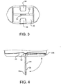
- the bottom surface 26 of the bottle 10a, 10b includes a mechanism for hanging the bottle 10a, 10b.
- the hangable hook projection 54 may be attached to, integral with, and extending from the bottom surface 26 of the bottle 10a, 10b.
- a hole or opening 56 may be defined in the hook projection 54.
- a c-shaped, s-shaped, or similar design could be used instead of the hole 56.
- the hook projection 54 is preferably integrally molded with a central rib 52 that is defined in the bottom surface 26 of the bottle 10a, 10b.
- a pair of locking channels 58 best shown in FIG.
- the hook projection 54 may also be molded into or contoured within the bottom surface 26 of the bottle 10a, 10b in order to receive and releasably secure the hook projection 54 in the non-deployed position 55b.
- the locking channels 58 may have a shape and surface area approximately equal to the shape and surface area of the hook projection 54.
- the hook projection 54 in the deployed position 55a, can be used to hang the bottle 10a, 10b in an upside-down configuration or the hook projection 54 can be received within the locking channel 58 to releasably secure the hook projection 54 in a non-deployed position 55b.
- the hook projection 54 is folded or bent over and secured out of the way such that the bottle 10a, 10b has a substantially flat bottom surface 26 and may be stood upright on the flat bottom.
- the bottles 10a, 10b may be obtained directly or indirectly from an upstream operation (not shown), such as a blow molding process known to one of ordinary skill in the art.
- the upstream operation may include blow molding hollow bottles 10 or other similar containers.
- plastic blow molded bottles 10 may be discharged from blow molds (not shown) and transported to the location of the multifunctional detabber apparatus 1.
- bottles 10a, 10b are exemplified in this document, it is envisioned that the multifunctional detabber apparatus 1 can be used with any type of bottle 10 or discrete article having any size, shape, and dimension including containers, vessels, flasks, vials, or the like known in the art.
- excess material or waste may be affixed to the formed bottle 10.
- excess molding waste 38 (see FIG. 5 ) may remain around the molded but uncut hook 53.
- a tail 25 (see FIG. 2A ) from the next bottle 10 in production may remain on the top or bottom areas of the bottle 10 or a dome 15 may remain above the neck portion 14 of the bottle 10.
- two or more bottles 10 may be joined together, for example, where each bottle 10 is attached to the other at the neck portion 14, and the bottles 10 need to be separated from one another (not shown).
- the bottles 10 may need to undergo a de-flashing, trimming, cutting, or separating process, for example, to trim the tail 25, remove the dome 15, and the like.
- the bottles 10 may be termed lightweight bottles 10 where "lightweight" is intended to denote an article weighing relatively little and as compared to a heavier article. Primarily, this distinction is made with reference to bottles 10 or containers which are empty or not filled. Thus, a bottle 10 which is empty is lightweight as compared to a similar bottle 10 which is filled (e.g., with a liquid or the like). It will be appreciated by one of ordinary skill in the art, however, that the weight of a bottle 10 may vary depending on the nature of the materials used to make the bottle 10 (e.g., plastic vs. glass), the shape and design of the bottle 10, the size or volume of the bottle 10, and the like. In an exemplary embodiment, the bottles 10 are lightweight bottles 10 or containers, which are hollow or empty.
- the hollow or empty bottles 10 may be plastic bottles 10 formed from an upstream blow molding operation.
- the lightweight, empty bottles 10 may weigh up to about 35 grams, about 8 grams to about 35 grams, about 10 grams to about 30 grams, or about 12 to about 18 grams, for example.
- the weight of the bottle 10 may also vary depending on the type and amount of scrap or waste material adhered to the bottle 10.
- the multifunctional detabber apparatus 1 may include a grabbing function, a trimming function, and a hook-closing function in one single cycle of operation of the multifunctional detabber apparatus 1.
- the multifunctional detabber apparatus 1 can incorporate a number of different tasks simultaneously or sequentially in a single cycle.
- the bottle 10 may undergo the following steps. First, the bottle 10 is formed, for example, by blow molding to produce a bottle with an uncut hook 53 surrounded by excess molding waste 38.
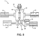
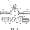
- FIGS. 7-10 sequentially show the respective positions of the multifunctional detabber apparatus 1 to perform each of these steps and are described in more detail below.
- the multifunctional detabber apparatus 1 may include a grabber comprised of a first jaw 40 and a second jaw 42 adapted to at least partially surround the main body portion 12 of the bottle 10 and prevent movement of the bottle 10.
- the first and second jaws 40, 42 move inwardly to surround the bottle 10 such that the uncut hook 53 protrudes below the first and second jaws 40, 42.
- the grabber stabilizes and prevents movement of the bottle 10 during the subsequent trimming and hook-closing operations.
- FIG. 1 shows that the first and second jaws 40, 42 may each include a cavity 44, 46, respectively, contoured to receive a portion, for example, about half, of the main body portion 12 of the bottle 10. As best seen in FIG.
- the bottle 10 includes a first face 34 and a second face 36.
- the contours of the first cavity 44 in the first jaw 40 may be shaped and sized so as to receive a portion of or substantially all of the first face 34 of the bottle 10.
- the contours of the second cavity 46 in the second jaw 42 may be shaped and sized so as to receive a portion of or substantially all of the second face 36 of the bottle.
- specifically designed cavities 44, 46 are depicted to substantially encase the first and second faces 34, 36 of the bottle 10, it is envisioned that any suitable design and configuration may be employed for the first and second jaws 40, 42 so long as the bottle 10 is secured and movement of the bottle 10 is prohibited.
- either or both of the first and second jaws 40, 42 may be moveable to encase the bottle 10 and inhibit movement.
- one of the first and second jaws 40, 42 may be stationary.
- both of the first and second jaws 40, 42 are moveable in a linear fashion to surround the bottle 10.
- the first jaw 40 and the second jaw 42 may be aligned in parallel and moveable relative to one another.
- the second jaw 42 may be aligned in parallel and juxtaposed to the first moveable jaw 40.
- the first jaw 40 and the second jaw 42 may further comprise first and second bumpers 80, 82, respectively, to guide the first jaw 40 and the second jaw 42 around the bottle 10.
- the first jaw 40 may include the first bumper 80 which extends from a central portion of the cavity 44 to ensure positioning of the first face 34 of the bottle 10 and guide the first jaw 40 into position (as shown in FIG. 12 ).
- the second jaw 42 may include the second bumper 82 which extends from a central portion of the cavity 46 to ensure positioning of the second face 36 of the bottle 10 and guide the second jaw 42 into position.
- the first and second bumpers 80, 82 may be of any suitable size, shape, and design.
- first and second bumpers 80, 82 may be comprised of bars adapted to contact the first and second faces 34, 36 of the bottle 10.
- FIG. 15 depicts a top view of the multifunctional detabber apparatus 1 including one suitable pair of bumpers 80, 82.
- the multifunctional detabber apparatus 1 may include one or more trimmers.
- the multifunctional detabber apparatus 1 is able to remove excess waste 38 from the bottles 10 remaining from the manufacturing process.
- the trimmer may be designed as one or more strikers or punches to produce the final shape of the hook projection 54 and remove the excess molding waste 38 from around the periphery of the hook projection 54.
- FIGS. 2A and 2B depict two types of bottles 10a, 10b that may be produced through blow molding.
- bottles 10a, 10b may be manufactured by extruding a parison of plastic material, capturing a portion of the parison within a mold, and inflating the portion of the parison that is within the mold against the walls of the mold to fabricate the specific shape of the container desired.
- the bottle 10a, 10b may be designed to be rigid or collapsible.
- bottles 10a, 10b are exemplified in this document, it is envisioned that any type of bottle (e.g., cylindrical) having any size and dimensions known in the art may be produced. Also, any suitable types of manufacturing processes including other types of molding processes could be used to produce the bottles 10.
- the trimmer may include a first striker 60 and a second striker 62, for example. After the first and second jaws 40, 42 are and remain engaged around the bottle 10, the first and second strikers 60, 62 are triggered, either simultaneously or sequentially.
- the first striker 60 may include a sharp edge or cutting surface contoured to create an outer periphery of the hook projection 54. Although two designs for the hook projection 54 are depicted in FIGS. 2A and 2B , the shape and design of the hook projection 54 and hence the shape of the first striker 60 is not especially limited, but may be of any suitable design and configuration.
- FIG. 13 provides a close-up, cross-sectional view of the multifunctional detabber apparatus shown in FIG. 12 including the first striker 60 for creating the outer periphery of the hook projection 54, the second striker 62 for forming the hole or opening 56 in the hook projection 54, and a striker plate 68, which supports the first and second strikers 60, 62.
- the multifunctional detabber apparatus 1 may include any suitable number and design of strikers or punches known to those skilled in the art necessary to create the desired hook projection 54.
- the trimmer may further comprise a counter-striker 64 juxtaposed to the first striker 60 and the second striker 62 to aid in trimming and supporting waste produced in the trimming or punching operation.
- the cutting surfaces of the first and second strikers 60, 62 may coincide with at least one surface of the counter-striker 64.
- the counter-striker 64 may be composed of two parts. The primary portion of the counter-striker 64 may be used to support the entire uncut hook 53. A secondary portion 64a of the counter-striker 64 may be used to support the hook projection 54, the area punched to form the hole 56, or a portion of these. As shown in FIG. 7 , the secondary portion 64a of the counter-striker 64 may be synchronized to move simultaneously with the second jaw 42 in order to support the hook projection 54 prior to trimming.
- the primary portion of the counter-striker 64 may be engaged to provide counter pressure to the first and second strikers 60, 62.
- the force of the first and second strikers 60, 62 may cause the counter-striker 64 to retract.
- FIG. 9 after trimming, each of the first and second strikers 60, 62 and the counter-striker 64 may retract to allow the molding waste 38 to drop away.
- the secondary portion 64a of the counter-striker 64 may remain engaged and in position to support the newly formed hook projection 54. If the molding waste 38 is properly cut off or removed in upstream operations or by the first and second strikers 60, 62, activation of the counter-striker 64 may not be required.
- the first and second strikers 60, 62 and the counter-striker 64 should be positioned beneath the bottom surface 26 of the bottle 10 in order to access the uncut hook 53 on the bottom surface 26 of the bottle 10.
- the first and second strikers 60, 62 may be positioned beneath the first moveable jaw 40.
- the moveable counter-striker 64 (and secondary portion 64a of the counter-striker 64) may be positioned beneath the second moveable jaw 42.
- the multifunctional detabber apparatus 1 may include a hook closer configured to bend or fold the hook projection 54 and secure the hook projection 54 in the locking channel 58 in the bottom surface 26 of the bottle 10.
- the hook closer may be provided to bend or maneuver the hanging hook projection 54 into the non-deployed position 55b (e.g., recessed into one of the locking channels 58) as shown in FIG. 4 .
- the bottle 10 may be produced with the hanging hook projection 54 in the extended or deployed position 55a.
- the hanging hook projection 54 can be bent or moved to the non-deployed position 55b.
- a mandrel 90 may extend from the secondary portion 64a of the counter-striker 64.
- the hook closer may include the mandrel 90 having an elongated shaft that extends to contact the hook projection 54.
- the mandrel 90 having a first end 92 may be positioned in parallel with and proximate to the bottom surface 26 of the bottle 10 such that when the first end 92 of the mandrel 90 extends, the first end 92 contacts one side of the hook projection 54.
- the first end 92 of the mandrel 90 may be rounded or semi-spherical, for example.
- the mandrel 90 may extend linearly to contact the hook projection 54 and fold the hook projection 54 flush with (or recessed into) the bottom surface 26 of the bottle 10. This configuration produces the non-deployed position 55b such that the hook projection 54 is substantially flush with the bottom surface 26 of the bottle 10.
- FIG. 14 provides a close-up, cross-sectional view of the multifunctional detabber apparatus 1 shown in FIG. 12 including the mandrel 90 in a retracted position.
- the mandrel 90 may be positioned proximate to and beneath the bottom surface 26 of the bottle 10 to access the hook projection 54 once formed.
- the moveable mandrel 90 may be positioned between the second moveable jaw 42 and the moveable counter-striker 64.
- the first and second jaws 40, 42; the first and second strikers 60, 62; the counter-striker 64; and the mandrel 90 may each be operated by any suitable equipment or device known in the art, such as by electric, hydraulic, or pneumatic motors or actuators.
- the first and second jaws 40, 42; the first and second strikers 60, 62; the counter-striker 64; and the mandrel 90 may be operated by a plurality of pneumatic servomotors, for example.
- a pneumatic servomotor 70 may be connected to and operable for the first jaw 40; a pneumatic servomotor 72 may be connected to and operable for the second jaw 42; a pneumatic servomotor 74 may be connected to and operable for the first striker 60 and the second striker 62; a pneumatic servomotor 76 may be connected to and operable for the counter-striker 64; and a pneumatic servomotor 78 may be connected to and operable for the mandrel 90.
- the pneumatic servomotors 70, 72, 74, 76, and 78 are preferably linear servomotors, which provide linear motion to each of the first and second jaws 40, 42; the first and second strikers 60, 62; the counter-striker 64; and the mandrel 90.
- the pneumatic servomotors 70, 72, 74, 76, and 78 may be operated under standard conditions known in the art.
- the servomotors 70, 72, 74, 76, and 78 may apply a pressure up to about 10 bar, preferably about 3-8 bar.
- the servomotors 70, 72, 74, and 76 may apply a pressure of about 6-8 bar to the first and second jaws 40, 42 and the first and second strikers 60, 62.
- the servomotor 78 may also apply a pressure of about 3-4 bar to the mandrel 90, for example.
- a method for producing the bottle 10 in a single cycle may include:
- a plurality of bottles 10 may be provided in a continuous stream from an upstream blow molding operation.
- the bottles 10 may be transported to the multifunctional detabber apparatus 1 using a claw head 84 on a spider tool 86.
- the claw head 84 is adapted to grab the neck portion 14 of the bottle 10, for example, using a mechanical grabber or a vacuum source (not shown), and the spider tool 86 includes an arm able to transport the bottle 10 seamlessly from an upstream operation, such as blow molding, and align the bottle 10 in between the first and second jaws 40, 42.
- the bottles 10 may be conveyed to and from the multifunctional detabber apparatus 1, for example, using a conveyor, such as a cleated conveyor, a flat belt conveyor, fan belt conveyor, or similar endless conveyance apparatus.
- the first and second moveable strikers 60, 62 may move simultaneously to punch the outer periphery of the hook projection 54 and the opening 56 in the hook projection 54 and subsequently retract after trimming. Subsequent to detabbing and cutting the hole or opening 56, the moveable mandrel 90 may extend to fold the hook projection 54 into the locking channel 58. The moveable mandrel 90 may subsequently retract to allow the bottle 10 to be released by the first and second jaws 40, 42.
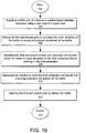
- FIG. 16 provides a flow chart summarizing the steps that may be performed in obtaining a bottle 10 in a single cycle of the multifunctional detabber apparatus 1.
- the multifunctional detabber apparatus 1 may be able to process up to about 40 bottles per minute.
- the bottles 10 are input at step 102 from one or more upstream operations.
- the bottles 10 are then supplied one at a time, at step 104, to the multifunctional detabber apparatus 1, for example, using the claw head 84 of the spider tool 86.
- the first and second jaws 40, 42 are closed to surround an outer periphery of the bottle 10 and secure and prevent movement of the bottle 10 during subsequent operations.
- the first and second strikers 60, 62 are operated and optionally, the counter-striker 64 is operated, to create an outer periphery of the hook projection 54 and an opening 56 in the hook projection 54.
- the first and second strikers 60, 62 are operated simultaneously.
- the mandrel 90 is deployed to close the hook projection 54 and secure the hook projection 54 in the locking channel 58 previously molded into the bottom surface 26 of the bottle 10 in an upstream operation.
- the first and second jaws 40, 42 are opened to release the bottle 10, and the bottle 10 is output at step 114 to one or more downstream operations.
- the multifunctional detabber apparatus 1 is able to sequentially or simultaneously incorporate multiple functionality, such as trimming, folding, and the like, in order to shorten the production line and remove costly downstream devices.
Landscapes
- Engineering & Computer Science (AREA)
- Mechanical Engineering (AREA)
- Manufacturing & Machinery (AREA)
- Physics & Mathematics (AREA)
- Thermal Sciences (AREA)
- Moulds For Moulding Plastics Or The Like (AREA)
- Blow-Moulding Or Thermoforming Of Plastics Or The Like (AREA)
- Containers Having Bodies Formed In One Piece (AREA)
- Details Of Rigid Or Semi-Rigid Containers (AREA)
- Packages (AREA)
Claims (15)
- Multifunktionale Detabber-Vorrichtung (1) zur Herstellung einer Flasche (10, 10a, 10b) in einem einzelnen Arbeitsgang, wobei die Flasche (10, 10a, 10b) einen Hauptkörperabschnitt (12) und eine Bodenfläche (26) mit einem Aufhängeransatz (54) aufweist, der mit der Bodenfläche (26) in einem Stück geformt ist und sich von dieser in einer entfalteten Position (55a) erstreckt, und mindestens ein Sperrkanal (58) in die Bodenfläche (26) eingeformt wird, um den Aufhängeransatz (54) in einer nicht entfalteten Position (55b) aufzunehmen und lösbar zu befestigen, wobei die multifunktionale Detabber-Vorrichtung (1) dadurch gekennzeichnet ist, dass sie aufweist:eine erste bewegbare Backe (40) und eine zweite bewegbare Backe (42), die parallel zur ersten bewegbaren Backe (40) und nebeneinander gelegt ausgerichtet ist, wobei die erste bewegbare Backe sowie die zweite bewegbare Backe (40, 42) so ausgestaltet sind, dass der Hauptkörperabschnitt (12) der Flasche (10, 10a, 10b) zumindest teilweise umgeben und die Flasche (10, 10a, 10b) gesichert wird;einen ersten bewegbaren Abstreifer (60) mit einer scharfen Kante, die gestaltet ist, einen äußeren Umfang des Aufhängeransatzes (54) zu erzeugen und Grat zu entfernen, einen zweiten bewegbaren Abstreifer mit einer scharfen Kante, die gestaltet ist, eine Öffnung (56) in dem Aufhängeransatz (54) zu erzeugen, und einen bewegbaren Gegenabstreifer (64), wobei der erste und der zweite bewegbare Abstreifer (60, 62) unterhalb der ersten bewegbaren Backe (40) angeordnet sind und der bewegbare Gegenabstreifer (64) unterhalb der zweiten bewegbaren Backe (42) angeordnet ist; undeinen bewegbaren Biegedorn (90), der zwischen der zweiten bewegbaren Backe (42) und dem bewegbaren Gegenabstreifer (64) angeordnet ist, wobei der Biegedorn (90) einen langgestreckten Schaft aufweist, der sich geradlinig erstreckt, um den Aufhängeransatz (54) zu biegen und den Aufhängeransatz (54) in dem mindestens einen Sperrkanal (58) in der Bodenfläche (26) der Flasche (10, 10a, 10b) zu sichern.
- Vorrichtung (1) nach Anspruch 1, wobei:die erste bewegbare Backe (40) und die zweite bewegbare Backe (42) ein Greifer ist;der erste bewegbare Abstreifer (60) und der zweite bewegbare Abstreifer (62) eine Kantenfräse ist; undder Biegedorn (90) ein Aufhängerschliesser ist.
- Vorrichtung (1) nach Anspruch 1, wobei die scharfen Kanten des ersten und des zweiten bewegbaren Abstreifers mit einer Fläche des bewegbaren Gegenabstreifers (64) zusammenfallen.
- Vorrichtung (1) nach Anspruch 2, wobei die Kantenfräse des Weiteren den Gegenabstreifer (64) aufweist, der nahe dem ersten Abstreifer (60) und dem zweiten bewegbaren Abstreifer (62) liegt, um beim Abschneiden und Halten von erzeugtem Verschnitt (38) zu unterstützen; wobei vorzugsweise
Schneidflächen des ersten und des zweiten bewegbaren Abstreifers (60, 62) mit einer Fläche des Gegenabstreifers (64) zusammenfallen. - Vorrichtung (1) nach Anspruch 1, des Weiteren umfassend eine Vielzahl von pneumatischen Servomotoren (70, 72, 74, 76, 78), die mit der ersten bewegbaren Backe (40), der zweiten bewegbaren Backe (42), dem ersten bewegbaren Abstreifer (60), dem zweiten bewegbaren Abstreifer, dem bewegbaren Gegenabstreifer (64) und dem bewegbaren Biegedorn (90) verbunden und für jedes betriebsfähig sind.
- Vorrichtung (1) nach Anspruch 2, des Weiteren umfassend eine Vielzahl von pneumatischen Servermotoren (70, 72, 74, 76, 78), die mit der ersten Backe, der zweiten Backe, dem ersten Abstreifer (60), dem zweiten bewegbaren Abstreifer (62) und dem Biegedorn (90) verbunden und für jedes betriebsfähig sind.
- Vorrichtung (1) nach Anspruch 5 oder Anspruch 6, wobei die Servomotoren (70, 72, 74, 76, 78) einen Druck von etwa 6 bis 8 bar auf die erste und die zweite Backe (40, 42) sowie den ersten und den zweiten bewegbaren Abstreifer (60, 62) aufbringen; oder
wobei einer der Servomotoren (70, 72, 74, 76, 78) einen Druck von etwa 3 bis 4 bar auf den Biegedorn (90) aufbringt. - Vorrichtung (1) nach Anspruch 2, wobei die erste Backe und die zweite Backe parallel ausgerichtet und relativ zueinander bewegbar sind.
- Vorrichtung (1) nach Anspruch 1 oder Anspruch 2, wobei die erste Backe und die zweite Backe jeweils Hohlräume aufweisen, die profiliert sind, um etwa die Hälfte des Hauptkörperabschnitts (12) der Flasche (10, 10a, 10b) aufzunehmen.
- Vorrichtung (1) nach Anspruch 2, wobei die Flasche (10, 10a, 10b) eine leere Flasche (10, 10a, 10b) ist, die etwa 8 bis etwa 35 g wiegt.
- Vorrichtung (1) nach Anspruch 2, wobei die erste Backe und die zweite Backe des Weiteren Puffer enthalten (80, 82) aufweisen, um die erste Backe und die zweite Backe um die Flasche (10, 10a, 10b) herum zu führen.
- Verfahren zur Herstellung einer Flasche (10, 10a, 10b) in einem einzelnen Arbeitsgang unter Verwendung der Vorrichtung (1) nach einem der Ansprüche 1 bis 11, wobei die Flasche (10, 10a, 10b) einen Hauptkörperteil (12) und eine Bodenfläche (26) mit einem Aufhängeransatz (54) aufweist, der mit der Bodenfläche (26) in einem Stück geformt ist und sich von dieser in einer entfalteten Position (55a) erstreckt, und mindestens ein Sperrkanal (58) in die Bodenfläche (26) eingeformt ist, um den Aufhängeransatz (54) aufzunehmen und in einer nicht entfalteten Position (55b) lösbar zu sichern, wobei das Verfahren umfasst:Greifen der Flasche (10, 10a, 10b) mit der ersten bewegbaren Backe und der zweiten bewegbaren Backe, um die Flasche (10, 10a, 10b) zu sichern und eine Bewegung zu verhindern;Entfernen von Grat um einen äußeren Umfang des Aufhängeransatzes (54) herum mit dem ersten Abstreifer (60) gegen den Gegenabstreifer (64);Schneiden eines Lochs in den Aufhängeransatz (54) mit dem zweiten bewegbaren Abstreifer (62) gegen den Gegenabstreifer (64), um einen Aufhänger zu erzeugen;Falten des Aufhängers bündig mit der Bodenfläche (26) der Flasche (10, 10a, 10b) und in den mindestens einen Sperrkanal (58) in der Bodenfläche (26) der Flasche (10, 10a, 10b) mit einem Biegedorn (90), der einen langgestreckten Schaft aufweist, wobei der Biegedorn (90) zwischen der zweiten bewegbaren Backe (42) und dem bewegbaren Gegenabstreifer (64) angeordnet ist; undLösen der Flasche (10, 10a, 10b) von der ersten und der zweiten Backe (40, 42).
- Verfahren nach Anspruch 12, wobei sich der erste und der zweite bewegbare Abstreifer gleichzeitig bewegen, um den äußeren Umfang des Aufhängeransatzes (54) und die Öffnung (56) im Aufhängeransatz (54) auszustanzen und anschließend nach dem Abschneiden zurückzuziehen.
- Verfahren nach Anspruch 13, wobei nach dem Entgraten und Schneiden des Lochs der bewegbare Biegedorn (90) ausfährt, um den Aufhänger zu dem mindestens einen Sperrkanal (58) zu falten.
- Verfahren nach Anspruch 12, wobei vor dem Greifen der Flasche (10, 10a, 10b) eine Vielzahl von Flaschen (10, 10a, 10b) in einem Durchlauf von einem stromaufwärts liegenden Blasformvorgang bereitgestellt werden.
Priority Applications (1)
| Application Number | Priority Date | Filing Date | Title |
|---|---|---|---|
| PL14703237T PL2969471T4 (pl) | 2013-03-13 | 2014-01-24 | Sposób oraz wielofunkcyjny przyrząd do docinania |
Applications Claiming Priority (2)
| Application Number | Priority Date | Filing Date | Title |
|---|---|---|---|
| US13/799,985 US9149975B2 (en) | 2013-03-13 | 2013-03-13 | Multifunctional detabber apparatus and method |
| PCT/US2014/012917 WO2014143415A1 (en) | 2013-03-13 | 2014-01-24 | Multifunctional detabber apparatus and method |
Publications (3)
| Publication Number | Publication Date |
|---|---|
| EP2969471A1 EP2969471A1 (de) | 2016-01-20 |
| EP2969471B1 EP2969471B1 (de) | 2017-03-22 |
| EP2969471B2 true EP2969471B2 (de) | 2020-04-29 |
Family
ID=50069336
Family Applications (1)
| Application Number | Title | Priority Date | Filing Date |
|---|---|---|---|
| EP14703237.9A Not-in-force EP2969471B2 (de) | 2013-03-13 | 2014-01-24 | Multifunktionelle detabber-vorrichtung und verfahren |
Country Status (10)
| Country | Link |
|---|---|
| US (2) | US9149975B2 (de) |
| EP (1) | EP2969471B2 (de) |
| JP (1) | JP6010248B2 (de) |
| CN (1) | CN105263692B (de) |
| AU (1) | AU2014228692A1 (de) |
| CA (1) | CA2905844A1 (de) |
| ES (1) | ES2626969T3 (de) |
| MX (1) | MX2015010787A (de) |
| PL (1) | PL2969471T4 (de) |
| WO (1) | WO2014143415A1 (de) |
Families Citing this family (6)
| Publication number | Priority date | Publication date | Assignee | Title |
|---|---|---|---|---|
| US10064535B2 (en) | 2014-10-06 | 2018-09-04 | The Clorox Company | All-in-one scrubbing tool with hook for substrate attachment |
| US10136789B2 (en) | 2014-10-06 | 2018-11-27 | The Clorox Company | All-in-one squeezable scrubbing tool |
| US10071399B2 (en) | 2014-10-06 | 2018-09-11 | The Clorox Company | Article for scrubbing and cleaning hard surfaces and a method for use thereof |
| EP3359460B1 (de) | 2015-10-09 | 2023-08-30 | Fresenius Kabi Deutschland GmbH | Behältnis zur aufnahme einer enteralen nährstofflösung |
| CN110271166A (zh) * | 2019-07-22 | 2019-09-24 | 昆山紫鼎塑胶有限公司 | 吹塑成型自动化产线 |
| CN111070642B (zh) * | 2019-12-12 | 2022-02-15 | 宁波大学 | 一种吹塑桶切边装置 |
Citations (3)
| Publication number | Priority date | Publication date | Assignee | Title |
|---|---|---|---|---|
| DE2225311A1 (de) † | 1972-05-25 | 1973-12-06 | Pmd Entwicklungswerk | Blas- und fuellmaschine zum kontinuierlichen herstellen gefuellter und verschlossener behaelter, insbesondere infusionsflaschen |
| DE10350152B3 (de) † | 2003-10-28 | 2004-10-21 | Daimlerchrysler Ag | Vorrichtung und Verfahren zum Herstellen eines Hohlkörpers |
| US20110240673A1 (en) † | 2010-04-01 | 2011-10-06 | Graham Packaging Company, L.P. | Collapsible container and method of making |
Family Cites Families (14)
| Publication number | Priority date | Publication date | Assignee | Title |
|---|---|---|---|---|
| US3606113A (en) | 1970-01-26 | 1971-09-20 | Monsanto Co | Removing waste from a molded article |
| US4178976A (en) * | 1978-02-10 | 1979-12-18 | Automatic Liquid Packaging, Inc. | Unitary, hermetically-sealed but pierceable dispensing container |
| US4282980A (en) | 1979-03-29 | 1981-08-11 | Baxter Travenol Laboratories, Inc. | Plastic hanger for containers |
| US4395378A (en) | 1981-05-14 | 1983-07-26 | Sewell Plastics, Inc. | Method for making an injection stretch blow molded container with an integral tab |
| JPS63135173A (ja) * | 1986-11-28 | 1988-06-07 | キヨ−ラク株式会社 | 輸液用プラスチック容器の製造方法 |
| JPH0684038B2 (ja) * | 1990-10-27 | 1994-10-26 | 日精エー・エス・ビー機械株式会社 | 吊具付き容器成形用プリフォーム及び吊具付き容器の成形方法 |
| DE9216933U1 (de) | 1991-12-20 | 1993-04-22 | B. Braun Medical AG, St. Gallen | Partiell kollabierendes Flüssigkeitsbehältnis aus Polyolefinen für Infusionen |
| JP3467300B2 (ja) | 1993-11-29 | 2003-11-17 | 日精エー・エス・ビー機械株式会社 | 吊り具付き容器 |
| JP3443706B2 (ja) * | 1993-11-30 | 2003-09-08 | キョーラク株式会社 | プラスチック中空容器の製造方法 |
| JP4172874B2 (ja) * | 1999-04-20 | 2008-10-29 | 株式会社タハラ | 栓体付き容器の製造装置およびその製造方法 |
| US6341684B1 (en) | 2000-03-16 | 2002-01-29 | Owens-Brockway Plastic Products Inc. | Blown plastic containers and method of handling same |
| JP4936614B2 (ja) * | 2001-06-08 | 2012-05-23 | 日精エー・エス・ビー機械株式会社 | 把手付容器及びその成形方法 |
| DE102007029810A1 (de) * | 2007-06-27 | 2009-01-02 | Fresenius Kabi Deutschland Gmbh | Vorformling und Verfahren zur Herstellung eines Behältnisses zur Aufnahme von Flüssigkeiten für medizinische Anwendungen |
| USD642065S1 (en) | 2010-04-01 | 2011-07-26 | Nestec S.A. | Container |
-
2013
- 2013-03-13 US US13/799,985 patent/US9149975B2/en not_active Expired - Fee Related
-
2014
- 2014-01-24 AU AU2014228692A patent/AU2014228692A1/en not_active Abandoned
- 2014-01-24 JP JP2016500178A patent/JP6010248B2/ja not_active Expired - Fee Related
- 2014-01-24 CA CA2905844A patent/CA2905844A1/en not_active Abandoned
- 2014-01-24 ES ES14703237.9T patent/ES2626969T3/es active Active
- 2014-01-24 CN CN201480015392.7A patent/CN105263692B/zh not_active Expired - Fee Related
- 2014-01-24 EP EP14703237.9A patent/EP2969471B2/de not_active Not-in-force
- 2014-01-24 PL PL14703237T patent/PL2969471T4/pl unknown
- 2014-01-24 WO PCT/US2014/012917 patent/WO2014143415A1/en not_active Ceased
- 2014-01-24 MX MX2015010787A patent/MX2015010787A/es unknown
-
2015
- 2015-08-28 US US14/838,901 patent/US9616619B2/en not_active Expired - Fee Related
Patent Citations (3)
| Publication number | Priority date | Publication date | Assignee | Title |
|---|---|---|---|---|
| DE2225311A1 (de) † | 1972-05-25 | 1973-12-06 | Pmd Entwicklungswerk | Blas- und fuellmaschine zum kontinuierlichen herstellen gefuellter und verschlossener behaelter, insbesondere infusionsflaschen |
| DE10350152B3 (de) † | 2003-10-28 | 2004-10-21 | Daimlerchrysler Ag | Vorrichtung und Verfahren zum Herstellen eines Hohlkörpers |
| US20110240673A1 (en) † | 2010-04-01 | 2011-10-06 | Graham Packaging Company, L.P. | Collapsible container and method of making |
Also Published As
| Publication number | Publication date |
|---|---|
| US9616619B2 (en) | 2017-04-11 |
| US9149975B2 (en) | 2015-10-06 |
| WO2014143415A1 (en) | 2014-09-18 |
| JP6010248B2 (ja) | 2016-10-19 |
| JP2016510702A (ja) | 2016-04-11 |
| PL2969471T3 (pl) | 2017-10-31 |
| MX2015010787A (es) | 2016-05-12 |
| EP2969471B1 (de) | 2017-03-22 |
| AU2014228692A1 (en) | 2015-09-03 |
| US20140265056A1 (en) | 2014-09-18 |
| CN105263692A (zh) | 2016-01-20 |
| EP2969471A1 (de) | 2016-01-20 |
| US20150367570A1 (en) | 2015-12-24 |
| PL2969471T4 (pl) | 2017-10-31 |
| ES2626969T3 (es) | 2017-07-26 |
| CN105263692B (zh) | 2017-06-09 |
| CA2905844A1 (en) | 2014-09-18 |
Similar Documents
| Publication | Publication Date | Title |
|---|---|---|
| US9616619B2 (en) | Method for producing a bottle using a multifunctional detabber apparatus | |
| RU2507068C2 (ru) | Способ изготовления пластикового изделия и форма для формования с раздувом | |
| US10682800B2 (en) | Blow mold tool with retractable base portion and method of blow molding using same | |
| CN103328184B (zh) | 用于制造塑料物品的方法以及由于实施这种方法的吹塑模具 | |
| RU2597310C2 (ru) | Способ изготовления пластмассового изделия, а также деталь формы для формования с раздувом | |
| JP2003505270A (ja) | 高効率吹込成形装置の型内への射出成形プレフォームの挿入 | |
| US9764508B2 (en) | Method for producing hollow bodies from thermoplastic material and apparatus for carrying out the method | |
| RU2005100832A (ru) | Устройство и способ для формования изделия с участком уменьшенного поперечного сечения | |
| US20140054829A1 (en) | Container with end feature and method of making same | |
| KR20180088851A (ko) | 블로 성형 장치 및 블로 성형 방법 | |
| EP3900912B1 (de) | Aus harz hergestellter behälter, verfahren zur herstellung eines aus harz hergestellten behälters, vorrichtung zur herstellung von harz und metallform | |
| EP3990252B1 (de) | Behälter mit reduziertem materialvolumen und system und verfahren zu seiner herstellung | |
| CA2551942A1 (en) | Container and blow mold assembly | |
| JP4164345B2 (ja) | 容器用ブロー成形分割型 | |
| CN110271166A (zh) | 吹塑成型自动化产线 | |
| EP2479019B1 (de) | Verfahren zum Einsetzen eines Griffs und eines Flaschenblasrohlings in eine Form von Blasformmodulen zur Herstellung von Kunststoffbehältern | |
| CN112689557A (zh) | 用于吹塑成型的模具,使用其制造树脂容器的方法,和树脂容器 | |
| CN110267791A (zh) | 用于热成型线的热成型热塑性片状坯件的站和相应的方法 | |
| JP6485690B2 (ja) | 樹脂製トレイ、及び、樹脂製トレイの製造方法 | |
| JPH0396319A (ja) | 底部に吊具を有する樹脂容器及びその射出延伸吹込成形方法 | |
| CA2791596C (en) | Blow mold tool with retractable base portion | |
| US20060121223A1 (en) | Container package | |
| RU19688U1 (ru) | Устройство для изготовления полых изделий | |
| EP1884474A2 (de) | Geformter Behälter aus Kunststoff, Verfahren und Form zu dessen Herstellung | |
| CN109910270A (zh) | 模具、成形站、成形轮、成形机、容器制造方法及此容器 |
Legal Events
| Date | Code | Title | Description |
|---|---|---|---|
| PUAI | Public reference made under article 153(3) epc to a published international application that has entered the european phase |
Free format text: ORIGINAL CODE: 0009012 |
|
| 17P | Request for examination filed |
Effective date: 20150924 |
|
| AK | Designated contracting states |
Kind code of ref document: A1 Designated state(s): AL AT BE BG CH CY CZ DE DK EE ES FI FR GB GR HR HU IE IS IT LI LT LU LV MC MK MT NL NO PL PT RO RS SE SI SK SM TR |
|
| AX | Request for extension of the european patent |
Extension state: BA ME |
|
| DAX | Request for extension of the european patent (deleted) | ||
| GRAP | Despatch of communication of intention to grant a patent |
Free format text: ORIGINAL CODE: EPIDOSNIGR1 |
|
| INTG | Intention to grant announced |
Effective date: 20161007 |
|
| RIC1 | Information provided on ipc code assigned before grant |
Ipc: B29C 69/00 20060101ALN20160926BHEP Ipc: B65D 23/00 20060101ALI20160926BHEP Ipc: B29C 49/74 20060101ALI20160926BHEP Ipc: B29C 49/42 20060101ALI20160926BHEP Ipc: B29L 31/00 20060101ALN20160926BHEP Ipc: B29C 49/50 20060101ALN20160926BHEP Ipc: B29C 67/00 20060101ALN20160926BHEP Ipc: B29C 49/54 20060101ALI20160926BHEP Ipc: B29C 49/20 20060101AFI20160926BHEP Ipc: B29C 37/02 20060101ALN20160926BHEP Ipc: B29C 49/72 20060101ALI20160926BHEP Ipc: B29C 49/04 20060101ALN20160926BHEP Ipc: B29C 53/02 20060101ALN20160926BHEP |
|
| GRAJ | Information related to disapproval of communication of intention to grant by the applicant or resumption of examination proceedings by the epo deleted |
Free format text: ORIGINAL CODE: EPIDOSDIGR1 |
|
| STAA | Information on the status of an ep patent application or granted ep patent |
Free format text: STATUS: REQUEST FOR EXAMINATION WAS MADE |
|
| GRAJ | Information related to disapproval of communication of intention to grant by the applicant or resumption of examination proceedings by the epo deleted |
Free format text: ORIGINAL CODE: EPIDOSDIGR1 |
|
| GRAP | Despatch of communication of intention to grant a patent |
Free format text: ORIGINAL CODE: EPIDOSNIGR1 |
|
| GRAJ | Information related to disapproval of communication of intention to grant by the applicant or resumption of examination proceedings by the epo deleted |
Free format text: ORIGINAL CODE: EPIDOSDIGR1 |
|
| GRAR | Information related to intention to grant a patent recorded |
Free format text: ORIGINAL CODE: EPIDOSNIGR71 |
|
| GRAS | Grant fee paid |
Free format text: ORIGINAL CODE: EPIDOSNIGR3 |
|
| STAA | Information on the status of an ep patent application or granted ep patent |
Free format text: STATUS: GRANT OF PATENT IS INTENDED |
|
| GRAA | (expected) grant |
Free format text: ORIGINAL CODE: 0009210 |
|
| STAA | Information on the status of an ep patent application or granted ep patent |
Free format text: STATUS: THE PATENT HAS BEEN GRANTED |
|
| INTC | Intention to grant announced (deleted) | ||
| RIC1 | Information provided on ipc code assigned before grant |
Ipc: B29C 49/42 20060101ALI20170123BHEP Ipc: B29C 53/02 20060101ALN20170123BHEP Ipc: B29L 31/00 20060101ALN20170123BHEP Ipc: B29C 49/72 20060101ALI20170123BHEP Ipc: B29C 49/20 20060101AFI20170123BHEP Ipc: B29C 49/50 20060101ALN20170123BHEP Ipc: B65D 23/00 20060101ALI20170123BHEP Ipc: B29C 37/02 20060101ALN20170123BHEP Ipc: B29C 49/74 20060101ALI20170123BHEP Ipc: B29C 49/04 20060101ALN20170123BHEP Ipc: B29C 69/00 20060101ALN20170123BHEP Ipc: B29C 49/54 20060101ALI20170123BHEP Ipc: B29C 67/00 20170101ALN20170123BHEP |
|
| RIC1 | Information provided on ipc code assigned before grant |
Ipc: B29C 49/74 20060101ALI20170202BHEP Ipc: B29C 37/02 20060101ALN20170202BHEP Ipc: B29C 49/42 20060101ALI20170202BHEP Ipc: B29C 49/72 20060101ALI20170202BHEP Ipc: B29C 67/00 20170101ALN20170202BHEP Ipc: B29C 49/04 20060101ALN20170202BHEP Ipc: B29C 49/20 20060101AFI20170202BHEP Ipc: B29C 49/54 20060101ALI20170202BHEP Ipc: B29C 49/50 20060101ALN20170202BHEP Ipc: B29C 69/00 20060101ALN20170202BHEP Ipc: B29L 31/00 20060101ALN20170202BHEP Ipc: B65D 23/00 20060101ALI20170202BHEP Ipc: B29C 53/02 20060101ALN20170202BHEP |
|
| AK | Designated contracting states |
Kind code of ref document: B1 Designated state(s): AL AT BE BG CH CY CZ DE DK EE ES FI FR GB GR HR HU IE IS IT LI LT LU LV MC MK MT NL NO PL PT RO RS SE SI SK SM TR |
|
| INTG | Intention to grant announced |
Effective date: 20170210 |
|
| REG | Reference to a national code |
Ref country code: GB Ref legal event code: FG4D |
|
| RIC1 | Information provided on ipc code assigned before grant |
Ipc: B29C 49/20 20060101AFI20170210BHEP Ipc: B29C 49/04 20060101ALN20170210BHEP Ipc: B29C 49/74 20060101ALI20170210BHEP Ipc: B29C 67/00 20170101ALN20170210BHEP Ipc: B29C 49/54 20060101ALI20170210BHEP Ipc: B29L 31/00 20060101ALN20170210BHEP Ipc: B29C 69/00 20060101ALN20170210BHEP Ipc: B29C 53/02 20060101ALN20170210BHEP Ipc: B65D 23/00 20060101ALI20170210BHEP Ipc: B29C 37/02 20060101ALN20170210BHEP Ipc: B29C 49/42 20060101ALI20170210BHEP Ipc: B29C 49/72 20060101ALI20170210BHEP Ipc: B29C 49/50 20060101ALN20170210BHEP |
|
| REG | Reference to a national code |
Ref country code: CH Ref legal event code: EP |
|
| REG | Reference to a national code |
Ref country code: AT Ref legal event code: REF Ref document number: 877283 Country of ref document: AT Kind code of ref document: T Effective date: 20170415 |
|
| RAP2 | Party data changed (patent owner data changed or rights of a patent transferred) |
Owner name: GRAHAM PACKAGING COMPANY, L.P. |
|
| REG | Reference to a national code |
Ref country code: IE Ref legal event code: FG4D |
|
| REG | Reference to a national code |
Ref country code: DE Ref legal event code: R096 Ref document number: 602014007826 Country of ref document: DE |
|
| REG | Reference to a national code |
Ref country code: NL Ref legal event code: FP |
|
| REG | Reference to a national code |
Ref country code: ES Ref legal event code: FG2A Ref document number: 2626969 Country of ref document: ES Kind code of ref document: T3 Effective date: 20170726 |
|
| PG25 | Lapsed in a contracting state [announced via postgrant information from national office to epo] |
Ref country code: NO Free format text: LAPSE BECAUSE OF FAILURE TO SUBMIT A TRANSLATION OF THE DESCRIPTION OR TO PAY THE FEE WITHIN THE PRESCRIBED TIME-LIMIT Effective date: 20170622 Ref country code: FI Free format text: LAPSE BECAUSE OF FAILURE TO SUBMIT A TRANSLATION OF THE DESCRIPTION OR TO PAY THE FEE WITHIN THE PRESCRIBED TIME-LIMIT Effective date: 20170322 Ref country code: HR Free format text: LAPSE BECAUSE OF FAILURE TO SUBMIT A TRANSLATION OF THE DESCRIPTION OR TO PAY THE FEE WITHIN THE PRESCRIBED TIME-LIMIT Effective date: 20170322 Ref country code: GR Free format text: LAPSE BECAUSE OF FAILURE TO SUBMIT A TRANSLATION OF THE DESCRIPTION OR TO PAY THE FEE WITHIN THE PRESCRIBED TIME-LIMIT Effective date: 20170623 Ref country code: LT Free format text: LAPSE BECAUSE OF FAILURE TO SUBMIT A TRANSLATION OF THE DESCRIPTION OR TO PAY THE FEE WITHIN THE PRESCRIBED TIME-LIMIT Effective date: 20170322 |
|
| REG | Reference to a national code |
Ref country code: LT Ref legal event code: MG4D |
|
| REG | Reference to a national code |
Ref country code: AT Ref legal event code: MK05 Ref document number: 877283 Country of ref document: AT Kind code of ref document: T Effective date: 20170322 |
|
| PG25 | Lapsed in a contracting state [announced via postgrant information from national office to epo] |
Ref country code: SE Free format text: LAPSE BECAUSE OF FAILURE TO SUBMIT A TRANSLATION OF THE DESCRIPTION OR TO PAY THE FEE WITHIN THE PRESCRIBED TIME-LIMIT Effective date: 20170322 Ref country code: BG Free format text: LAPSE BECAUSE OF FAILURE TO SUBMIT A TRANSLATION OF THE DESCRIPTION OR TO PAY THE FEE WITHIN THE PRESCRIBED TIME-LIMIT Effective date: 20170622 Ref country code: LV Free format text: LAPSE BECAUSE OF FAILURE TO SUBMIT A TRANSLATION OF THE DESCRIPTION OR TO PAY THE FEE WITHIN THE PRESCRIBED TIME-LIMIT Effective date: 20170322 Ref country code: RS Free format text: LAPSE BECAUSE OF FAILURE TO SUBMIT A TRANSLATION OF THE DESCRIPTION OR TO PAY THE FEE WITHIN THE PRESCRIBED TIME-LIMIT Effective date: 20170322 |
|
| PG25 | Lapsed in a contracting state [announced via postgrant information from national office to epo] |
Ref country code: EE Free format text: LAPSE BECAUSE OF FAILURE TO SUBMIT A TRANSLATION OF THE DESCRIPTION OR TO PAY THE FEE WITHIN THE PRESCRIBED TIME-LIMIT Effective date: 20170322 Ref country code: AT Free format text: LAPSE BECAUSE OF FAILURE TO SUBMIT A TRANSLATION OF THE DESCRIPTION OR TO PAY THE FEE WITHIN THE PRESCRIBED TIME-LIMIT Effective date: 20170322 Ref country code: RO Free format text: LAPSE BECAUSE OF FAILURE TO SUBMIT A TRANSLATION OF THE DESCRIPTION OR TO PAY THE FEE WITHIN THE PRESCRIBED TIME-LIMIT Effective date: 20170322 Ref country code: CZ Free format text: LAPSE BECAUSE OF FAILURE TO SUBMIT A TRANSLATION OF THE DESCRIPTION OR TO PAY THE FEE WITHIN THE PRESCRIBED TIME-LIMIT Effective date: 20170322 Ref country code: SK Free format text: LAPSE BECAUSE OF FAILURE TO SUBMIT A TRANSLATION OF THE DESCRIPTION OR TO PAY THE FEE WITHIN THE PRESCRIBED TIME-LIMIT Effective date: 20170322 |
|
| PG25 | Lapsed in a contracting state [announced via postgrant information from national office to epo] |
Ref country code: IS Free format text: LAPSE BECAUSE OF FAILURE TO SUBMIT A TRANSLATION OF THE DESCRIPTION OR TO PAY THE FEE WITHIN THE PRESCRIBED TIME-LIMIT Effective date: 20170722 Ref country code: SM Free format text: LAPSE BECAUSE OF FAILURE TO SUBMIT A TRANSLATION OF THE DESCRIPTION OR TO PAY THE FEE WITHIN THE PRESCRIBED TIME-LIMIT Effective date: 20170322 Ref country code: PT Free format text: LAPSE BECAUSE OF FAILURE TO SUBMIT A TRANSLATION OF THE DESCRIPTION OR TO PAY THE FEE WITHIN THE PRESCRIBED TIME-LIMIT Effective date: 20170724 |
|
| REG | Reference to a national code |
Ref country code: DE Ref legal event code: R026 Ref document number: 602014007826 Country of ref document: DE |
|
| PLBI | Opposition filed |
Free format text: ORIGINAL CODE: 0009260 |
|
| PLAX | Notice of opposition and request to file observation + time limit sent |
Free format text: ORIGINAL CODE: EPIDOSNOBS2 |
|
| 26 | Opposition filed |
Opponent name: GREINER PACKAGING INTERNATIONAL GMBH Effective date: 20171220 |
|
| REG | Reference to a national code |
Ref country code: FR Ref legal event code: PLFP Year of fee payment: 5 |
|
| PG25 | Lapsed in a contracting state [announced via postgrant information from national office to epo] |
Ref country code: DK Free format text: LAPSE BECAUSE OF FAILURE TO SUBMIT A TRANSLATION OF THE DESCRIPTION OR TO PAY THE FEE WITHIN THE PRESCRIBED TIME-LIMIT Effective date: 20170322 |
|
| PG25 | Lapsed in a contracting state [announced via postgrant information from national office to epo] |
Ref country code: SI Free format text: LAPSE BECAUSE OF FAILURE TO SUBMIT A TRANSLATION OF THE DESCRIPTION OR TO PAY THE FEE WITHIN THE PRESCRIBED TIME-LIMIT Effective date: 20170322 |
|
| PLBB | Reply of patent proprietor to notice(s) of opposition received |
Free format text: ORIGINAL CODE: EPIDOSNOBS3 |
|
| REG | Reference to a national code |
Ref country code: CH Ref legal event code: PL |
|
| PG25 | Lapsed in a contracting state [announced via postgrant information from national office to epo] |
Ref country code: LU Free format text: LAPSE BECAUSE OF NON-PAYMENT OF DUE FEES Effective date: 20180124 |
|
| REG | Reference to a national code |
Ref country code: IE Ref legal event code: MM4A |
|
| PG25 | Lapsed in a contracting state [announced via postgrant information from national office to epo] |
Ref country code: LI Free format text: LAPSE BECAUSE OF NON-PAYMENT OF DUE FEES Effective date: 20180131 Ref country code: CH Free format text: LAPSE BECAUSE OF NON-PAYMENT OF DUE FEES Effective date: 20180131 |
|
| PG25 | Lapsed in a contracting state [announced via postgrant information from national office to epo] |
Ref country code: IE Free format text: LAPSE BECAUSE OF NON-PAYMENT OF DUE FEES Effective date: 20180124 |
|
| PLAY | Examination report in opposition despatched + time limit |
Free format text: ORIGINAL CODE: EPIDOSNORE2 |
|
| PGFP | Annual fee paid to national office [announced via postgrant information from national office to epo] |
Ref country code: NL Payment date: 20190125 Year of fee payment: 6 Ref country code: PL Payment date: 20190111 Year of fee payment: 6 Ref country code: IT Payment date: 20190125 Year of fee payment: 6 |
|
| PGFP | Annual fee paid to national office [announced via postgrant information from national office to epo] |
Ref country code: BE Payment date: 20190131 Year of fee payment: 6 |
|
| PG25 | Lapsed in a contracting state [announced via postgrant information from national office to epo] |
Ref country code: MC Free format text: LAPSE BECAUSE OF FAILURE TO SUBMIT A TRANSLATION OF THE DESCRIPTION OR TO PAY THE FEE WITHIN THE PRESCRIBED TIME-LIMIT Effective date: 20170322 |
|
| PLBC | Reply to examination report in opposition received |
Free format text: ORIGINAL CODE: EPIDOSNORE3 |
|
| PG25 | Lapsed in a contracting state [announced via postgrant information from national office to epo] |
Ref country code: MT Free format text: LAPSE BECAUSE OF NON-PAYMENT OF DUE FEES Effective date: 20180124 |
|
| PUAH | Patent maintained in amended form |
Free format text: ORIGINAL CODE: 0009272 |
|
| STAA | Information on the status of an ep patent application or granted ep patent |
Free format text: STATUS: PATENT MAINTAINED AS AMENDED |
|
| PG25 | Lapsed in a contracting state [announced via postgrant information from national office to epo] |
Ref country code: TR Free format text: LAPSE BECAUSE OF FAILURE TO SUBMIT A TRANSLATION OF THE DESCRIPTION OR TO PAY THE FEE WITHIN THE PRESCRIBED TIME-LIMIT Effective date: 20170322 |
|
| 27A | Patent maintained in amended form |
Effective date: 20200429 |
|
| AK | Designated contracting states |
Kind code of ref document: B2 Designated state(s): AL AT BE BG CH CY CZ DE DK EE ES FI FR GB GR HR HU IE IS IT LI LT LU LV MC MK MT NL NO PL PT RO RS SE SI SK SM TR |
|
| REG | Reference to a national code |
Ref country code: DE Ref legal event code: R102 Ref document number: 602014007826 Country of ref document: DE |
|
| PGFP | Annual fee paid to national office [announced via postgrant information from national office to epo] |
Ref country code: GB Payment date: 20200129 Year of fee payment: 7 |
|
| PG25 | Lapsed in a contracting state [announced via postgrant information from national office to epo] |
Ref country code: CY Free format text: LAPSE BECAUSE OF FAILURE TO SUBMIT A TRANSLATION OF THE DESCRIPTION OR TO PAY THE FEE WITHIN THE PRESCRIBED TIME-LIMIT Effective date: 20170322 Ref country code: HU Free format text: LAPSE BECAUSE OF FAILURE TO SUBMIT A TRANSLATION OF THE DESCRIPTION OR TO PAY THE FEE WITHIN THE PRESCRIBED TIME-LIMIT; INVALID AB INITIO Effective date: 20140124 Ref country code: MK Free format text: LAPSE BECAUSE OF NON-PAYMENT OF DUE FEES Effective date: 20170322 |
|
| PGFP | Annual fee paid to national office [announced via postgrant information from national office to epo] |
Ref country code: FR Payment date: 20200128 Year of fee payment: 7 |
|
| PG25 | Lapsed in a contracting state [announced via postgrant information from national office to epo] |
Ref country code: AL Free format text: LAPSE BECAUSE OF FAILURE TO SUBMIT A TRANSLATION OF THE DESCRIPTION OR TO PAY THE FEE WITHIN THE PRESCRIBED TIME-LIMIT Effective date: 20170322 |
|
| PGFP | Annual fee paid to national office [announced via postgrant information from national office to epo] |
Ref country code: DE Payment date: 20200327 Year of fee payment: 7 |
|
| REG | Reference to a national code |
Ref country code: NL Ref legal event code: MM Effective date: 20200201 |
|
| REG | Reference to a national code |
Ref country code: BE Ref legal event code: MM Effective date: 20200131 |
|
| PG25 | Lapsed in a contracting state [announced via postgrant information from national office to epo] |
Ref country code: NL Free format text: LAPSE BECAUSE OF NON-PAYMENT OF DUE FEES Effective date: 20200201 |
|
| PG25 | Lapsed in a contracting state [announced via postgrant information from national office to epo] |
Ref country code: BE Free format text: LAPSE BECAUSE OF NON-PAYMENT OF DUE FEES Effective date: 20200131 |
|
| PG25 | Lapsed in a contracting state [announced via postgrant information from national office to epo] |
Ref country code: IT Free format text: LAPSE BECAUSE OF NON-PAYMENT OF DUE FEES Effective date: 20200124 Ref country code: ES Free format text: LAPSE BECAUSE OF FAILURE TO SUBMIT A TRANSLATION OF THE DESCRIPTION OR TO PAY THE FEE WITHIN THE PRESCRIBED TIME-LIMIT Effective date: 20200429 |
|
| REG | Reference to a national code |
Ref country code: DE Ref legal event code: R119 Ref document number: 602014007826 Country of ref document: DE |
|
| GBPC | Gb: european patent ceased through non-payment of renewal fee |
Effective date: 20210124 |
|
| PG25 | Lapsed in a contracting state [announced via postgrant information from national office to epo] |
Ref country code: FR Free format text: LAPSE BECAUSE OF NON-PAYMENT OF DUE FEES Effective date: 20210131 |
|
| PG25 | Lapsed in a contracting state [announced via postgrant information from national office to epo] |
Ref country code: DE Free format text: LAPSE BECAUSE OF NON-PAYMENT OF DUE FEES Effective date: 20210803 Ref country code: GB Free format text: LAPSE BECAUSE OF NON-PAYMENT OF DUE FEES Effective date: 20210124 |
|
| PG25 | Lapsed in a contracting state [announced via postgrant information from national office to epo] |
Ref country code: PL Free format text: LAPSE BECAUSE OF NON-PAYMENT OF DUE FEES Effective date: 20200124 |