EP2969332B1 - Gehrungssäge mit bürstenlosem antriebsmotor - Google Patents
Gehrungssäge mit bürstenlosem antriebsmotor Download PDFInfo
- Publication number
- EP2969332B1 EP2969332B1 EP14771125.3A EP14771125A EP2969332B1 EP 2969332 B1 EP2969332 B1 EP 2969332B1 EP 14771125 A EP14771125 A EP 14771125A EP 2969332 B1 EP2969332 B1 EP 2969332B1
- Authority
- EP
- European Patent Office
- Prior art keywords
- motor
- saw
- drive
- assembly
- gear
- Prior art date
- Legal status (The legal status is an assumption and is not a legal conclusion. Google has not performed a legal analysis and makes no representation as to the accuracy of the status listed.)
- Not-in-force
Links
Images


Classifications
-
- B—PERFORMING OPERATIONS; TRANSPORTING
- B23—MACHINE TOOLS; METAL-WORKING NOT OTHERWISE PROVIDED FOR
- B23D—PLANING; SLOTTING; SHEARING; BROACHING; SAWING; FILING; SCRAPING; LIKE OPERATIONS FOR WORKING METAL BY REMOVING MATERIAL, NOT OTHERWISE PROVIDED FOR
- B23D47/00—Sawing machines or sawing devices working with circular saw blades, characterised only by constructional features of particular parts
- B23D47/12—Sawing machines or sawing devices working with circular saw blades, characterised only by constructional features of particular parts of drives for circular saw blades
- B23D47/126—Angle drives
-
- B—PERFORMING OPERATIONS; TRANSPORTING
- B23—MACHINE TOOLS; METAL-WORKING NOT OTHERWISE PROVIDED FOR
- B23D—PLANING; SLOTTING; SHEARING; BROACHING; SAWING; FILING; SCRAPING; LIKE OPERATIONS FOR WORKING METAL BY REMOVING MATERIAL, NOT OTHERWISE PROVIDED FOR
- B23D45/00—Sawing machines or sawing devices with circular saw blades or with friction saw discs
- B23D45/04—Sawing machines or sawing devices with circular saw blades or with friction saw discs with a circular saw blade or the stock carried by a pivoted lever
-
- B—PERFORMING OPERATIONS; TRANSPORTING
- B23—MACHINE TOOLS; METAL-WORKING NOT OTHERWISE PROVIDED FOR
- B23D—PLANING; SLOTTING; SHEARING; BROACHING; SAWING; FILING; SCRAPING; LIKE OPERATIONS FOR WORKING METAL BY REMOVING MATERIAL, NOT OTHERWISE PROVIDED FOR
- B23D47/00—Sawing machines or sawing devices working with circular saw blades, characterised only by constructional features of particular parts
- B23D47/12—Sawing machines or sawing devices working with circular saw blades, characterised only by constructional features of particular parts of drives for circular saw blades
Definitions
- the present disclosure relates to a miter saw having a drive mechanism for providing power to the miter saw.
- Such power tools may be a planer, miter saw, bevel saw, reciprocating saw, jig saw, compound saw, vertical saw, band saw, router, circular saw, or the like.
- a common feature among these types of tools is that the drive motor and driven tool are carried by the same structure.
- the miter saw 10 includes a saw assembly 12 that is supported on a base assembly 14 by a bevel mount 16.
- the bevel mount for this tool is configured to allow the saw assembly to pivot up and down relative to the base assembly in order to perform the cut.
- the bevel mount 16 is configured to allow the saw assembly to be oriented at a user-defined miter angle and may also be configured to allow the saw assembly to be positioned at a non-perpendicular angle relative to the work surface 15 of the base assembly.
- the saw assembly 12 is connected to the bevel mount 16 by an arm assembly 18.
- the arm assembly includes a housing 19 that supports the motor M and may be provided with handle assembly 20 that can be grasped by the operator to control the movement of the saw assembly when performing a cut.
- the housing 19 of the arm assembly contains the electrical and/or electronic components of the power tool 10 , with electrical power fed to the motor M and electrical components by a power cord C. In the miter saw of FIGS.
- the motor M is supported on the rotational axis of the tool, in this case a rotary saw blade.
- the saw blade is mounted directly on the output shaft of the motor so that the blade speed matches the motor speed.
- a gearing arrangement may be provided to step up or step down the motor speed for driving the tool.
- the drive motor M has traditionally been a universal AC motor because these types of motors are capable of the rotational speeds and torques necessary for an effective power tool.
- the benefits of the universal motor are countered by the bulkiness of the motor.
- the motor M projects significantly outward from the arm assembly 18 , in many cases doubling the overall width of the power tool 10.
- the size and weight of the traditional motor affects the moment of inertia of the power tool.
- US2011107892A1 discloses a miter saw comprising: a base assembly; a saw assembly including a saw blade having a drive shaft wherein the saw assembly is supported on the base assembly by a bevel mount; an arm assembly connecting the saw assembly to the bevel mount, the arm assembly including an arm housing and a handle that can be grasped by an operator to control the movement of the saw assembly when performing a cut; a drive motor housing projecting inwardly towards the drive shaft, wherein the arm assembly is arranged directly above and in line with saw assembly with the drive motor housing laterally offset from the arm housing; a brushless DC BLDC motor having an output shaft and being mounted within said motor housing and a drive train mounted within said motor housing wherein said drive train operably connects the output shaft of the BLDC motor to said drive shaft, wherein the drive train
- US 2008/289843 A1 discloses an apparatus having a main body portion and an articulating arm.
- the main body has a power source, a drive motor, and a drive shaft.
- the drive shaft extends into the articulating arm which has a first section rotatable about the drive shaft.
- the articulating arm also has a second section which is seated on a first transversely aligned drive shaft interoperating with the drive shaft itself.
- the first transversely aligned drive shaft transmits rotational work to a second transversely aligned drive shaft which supports a third section.
- a third section interoperates with a spindle section which receives the rotational work from the second transversely aligned drive shaft to accomplish rotational work on the securing element.
- a miter saw defined by the features of claim 1 is provided. Further preferred embodiments are defined by the features of dependent claims 2-4.
- BLDC motors Brushless DC motors or electronically commutated motors (referred to herein generally as BLDC motors) have been developed that can generate rotational speeds and torques comparable to the conventional universal AC motor.
- BLDC motors occupy a much smaller envelop than the universal motor, typically about half the length and occupying less than one-fourth the volume of a comparably powered universal motor.
- the much smaller envelop provided by the BLDC motor permits significant modifications to the overall size and shape of a power tool.
- the small size of the BLDC motor permits different indirect drive train arrangements, rather than the direct drive arrangement of the AC motor.
- a BLDC motor 30 is coupled to the drive shaft S of the working tool, such as the saw blade of the saw assembly 12 described above, by way of a gear train 35 shown in FIG. 2(a) .
- the gear train includes a pinion gear 36 engaged to the output shaft 31 of the BLDC motor 30.
- a bevel gear 37 is engaged to the drive shaft S of the saw blade and in meshed engagement with the pinion gear 36.
- the gear train 35 thus provides a right angle drive for the saw blade, which means that the BLDC motor 30 does not need to project laterally outward from the arm assembly, as in prior power tools.
- the BLDC motor 30 and drive train 35 may be compactly contained within the housing 19' of the arm assembly 18 i , as shown in FIGS. 2(b)- (c).
- the control unit or circuit board for the BLDC motor may also be mounted within the housing 19 i .
- the BLDC motor 30 may be arranged at an angle within the housing, as depicted in FIG. 2(b) .
- the impact on the overall size of the power tool 10 i relative to the traditional power tool 10 can be appreciated by comparing the top views of FIG. 1(b) and FIG. 2(c) .
- the absence of the conventional motor M significantly reduces the lateral extent of the tool, without requiring modification to the handle assembly 20 or bevel mount 16.
- the drive ratio for the drive train may be adjusted according to the output speed of the BLDC motor and the speed requirements for the saw blade. In one specific embodiment, for a 4000 rpm saw blade speed, the gear train is configured for a gear ratio of 3.45:1 for a BLDC motor having a no-load operating speed of 1150 rpm.
- a worm gear 46 is engaged to the output shaft 31 of a BLDC motor 30.
- the worm gear meshes with a spur gear 47 that is engaged to the drive shaft S of the tool or saw blade.
- the worm gear may mesh with the spur gear of the gear train 45 at any angular location around the circumference of the gear.
- the BLDC 30 and gear train 45 may be mounted with the modified housing 19 i , as illustrated in FIGS. 3(b) -(c).
- One advantage of the worm gear 46 over the pinion gear 36 is that the worm gear may be positioned directly over the spur gear, as seen in FIG.
- the final ratio of the gear train 45 may be calibrated to match the BLDC motor speed with the desired shaft speed for the saw blade.
- the worm gear 46 is a 4 start gear while the spur gear 47 is a 30 tooth gear for a final ratio of 7.5:1.
- the BLDC motor 30 may be provided with a fan 32 at the rear face of the motor.
- the fan may be directly driven by the output shaft 31 of the motor in order to cool the motor and the interior of the housing 19 i . It should be appreciated that the fan may be incorporated into the BLDC motor in each embodiment disclosed herein.
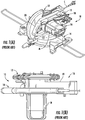
- FIG. 4(a) Another gear train 55 is shown in FIG. 4(a) that incorporates a pinion gear 56 engaged to the output shaft 31 of the BLDC motor 30.
- the pinion gear meshes with the inboard face (i.e., facing the saw blade) of a bevel gear 57 which drives an idler gear 59 mounted on the bevel gear shaft 58.
- the idler gear 59 drives an intermediate spur gear 60 which meshes with a drive gear 61 engaged to the drive shaft S of the saw blade.
- the gear train 55 allows the BLDC motor 30 to be arranged nearly parallel to the housing 19". as shown in FIG. 4(b) , rather than at an angle as in the embodiments of FIGS. 2-3 .
- the housing 19" may have a reduced profile at the end coupled to the bevel mount 16 , with a more tubular shape.
- the modified configuration of the housing 19" also permits a modification to the orientation of the handle assembly 20" to accommodate an overhand grip by the operator, as shown in FIG. 4(b) .
- the final ratio of the gear train 55 may be adjusted by selection of the bevel and spur gears.
- an 11 tooth pinion gear 56 meshes with a 38 tooth bevel gear 57.
- An 18 tooth idler gear 59 drives an 11/22 tooth gear set 60, 61 to the drive shaft S.
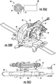
- the gear train 65 of FIG. 5(a) incorporates a worm gear 66 mounted to the output shaft 31 of the BLDC motor 30.
- the worm gear meshes with a spur gear 67 which shares an axle 68 with an idler gear 69.
- the idler gear meshes with the drive gear 70 to drive the shaft S of the saw blade.
- the drive train 65 of FIG. 5(a) allows the motor to be oriented nearly parallel to the housing 19ii , as shown in FIG. 5(b) .
- the gear train 65 is slightly more compact laterally because the worm gear 66 resides directly above the spur gear 67.
- a final gear ratio of 6.96:1 can be achieved in one embodiment with a worm gear 66 having 4 starts meshing with a 30 tooth spur gear 67.
- the gear set 69/70 to the drive shaft S can have a 28/26 tooth ratio.
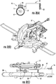
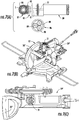
- the reduced size of the BLDC motor 30 also provides a benefit for a laterally mounted motor, such as the arrangement shown in FIGS. 6(b) -(c).
- a gear train 75 is provided that steps down the speed of the motor output shaft 31.
- the gear train 75 is in the form of a planetary gear set as shown in FIG. 6(a) .
- the sun or pinion gear 76 is mounted on the motor output shaft 31 and meshes with planetary gears 77 supported on a carrier 78.
- the carrier includes a hub 79 projecting inward for engagement with the saw blade drive shaft.
- the planetary gears 77 revolve within a fixed ring gear 80 to multiply the pinion gear speed.
- the pinion gear can have 12 teeth
- the ring gear can have 72 teeth
- the planetary gears can have 30 teeth to achieve a final ratio of 7.0:1.
- FIG. 6(c) projects laterally from the arm assembly 18
- a comparison of FIG. 6(c) to FIG. 1(c) illustrates the significantly reduced profile achieved by the BLDC motor.
- the lower weight of the BLDC motor provides improved inertia characteristics, making the arm easier to move in a precise, controlled fashion.
- the planetary gear arrangement may be implemented in a vertically mounted concept, such as shown in FIGS. 7(b) -(c).
- the gear train 85 shown in FIG. 7(a) includes a planetary set 86 that drives a right angle bevel set 87 to power the saw blade drive shaft S.
- the planetary set 86 includes a pinion gear 88 engaged to the output shaft 31 of the motor.
- the pinion gear meshes with planetary gears 89 which rotate within a fixed ring gear 90.
- the planetary gears are supported by a carrier 91 which drives the bevel gear 92 of the bevel set 87.
- the final bevel gear 93 is engaged to the shaft S.
- the small size of the BLDC motor 30 does not significantly alter the envelop of the power tool, since the BLDC motor does not project significantly above the top of the saw assembly 12.
- a modified arm assembly 18 iii shown in FIG. 8(b) is provided on a power tool in which the arm housing 19 iii is an exaggerated C-shape from its engagement to the bevel mount 16 to the handle 20 iii .
- the housing 19 iii includes a drive motor housing 103 that projects inwardly from the C-shaped housing 19 iii toward the fan blade shaft S.
- the arm assembly 18 iii is arranged directly above and in line with saw assembly 12 , with the drive motor housing 103 laterally offset from the arm housing 19 iii .
- This alignment of the saw assembly and arm assembly eliminates any torquing that might occur with an arm assembly that is laterally offset from the saw blade. Instead, the line of action of the force applied by the operator to the handle 20 iii is transmitted directly with no moment to the saw assembly 12.
- the inline arrangement makes the power tool well-suited for either left-handed or right-handed use, and provides maximum workpiece visibility from both sides of the saw assembly 12.
- the drive train includes a pinion gear 96 mounted to the output shaft 31 of the motor 30 that meshes with a bevel gear 97.
- the bevel gear includes a central hub 98 that supports a spur gear 99 which then meshes with a spur gear 100 engaged to the drive shaft S of the saw blade.
- the drive train 95 can be aligned along the axis of the motor housing 103 , generally perpendicular to the modified arm housing 19 iii .
- a final gear ratio of 6.91:1 can be achieved by a bevel gear set of 11/38 teeth and a spur gear set of 11/22 teeth.
- a modified arm assembly 18 iv includes a housing 19 iv and handle 20 iv that are similar to the housing 19 i and handle 20 i shown in FIG. 2(b) except that the drive motor 30 is supported in a housing 112 at the rear of the arm assembly, adjacent the bevel mount 16.
- This rearrangement of the drive motor is achieved by the drive train 105 shown in FIG. 9(a) that includes a belt 109.
- the drive train 105 includes a spur gear 106 driven by the motor 30 and which meshes with a spur gear 107.
- the spur gear 107 includes a pulley wheel 108 that drives a belt 109 to rotate another pulley wheel 110 connected to the saw blade shaft S.
- the pulleys and belt may be a friction drive or may incorporate teeth to prevent belt slip.
- the spur gear 106 may be positioned inside the belt 109 to reduce the overall length of the drive train 105.
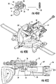
- the belt configuration may be implemented in an angle drive train 115 shown in FIG. 10(a) .
- the drive train 115 includes a pinion gear 116 engaged to the motor output shaft 31 and which meshes with a bevel gear 117.
- the bevel gear includes a pulley wheel 119 mounted to a hub 118 of the bevel gear.
- the pulley wheel 119 drives a belt 120 that in turn drives an opposite pulley wheel 121 coupled to the drive shaft S.
- the drive train 115 may assume a near right angle between the BLDC motor 30 and the driven pulley wheel 121.
- the arm assembly 18 v includes a motor housing 123 that carries the drive train and engages the bevel mount 16. As shown in the top view of FIG. 10(c) the drive train 115 fits into a narrow width so that the arm assembly housing 19 v presents a narrow lateral profile.
- a drive train 125 positions the BLDC motor 30 entirely inside the drive belt.
- the motor drives a pinion gear 126 that meshes with a bevel gear 127.
- the bevel gear includes a hub 128 that carries a pulley wheel 129.
- the belt 130 is engaged between the pulley wheel 129 and an opposite pulley wheel 131 that is engaged to the drive shaft S. Due to the small size of the BLDC motor, it fits snugly within the belt 130.
- the drive train 125 thus allows for another alternative arm assembly 18 vi that includes a housing 19 vi in the form of a vertical beam extending from the bevel mount 16.
- the modified handle 20 vi is offset from the housing 19 vi to be positioned directly above and in line with the saw assembly 12 , as shown in FIGS. 11b )-(c).
- the drive train 125 is disposed within a housing portion 132 that extends from the housing 19 vi to the drive shaft S of the saw blade.
- the drive trains 115 and 125 that combine the bevel gear set and belt drive set can have a final gear ratio of 6.91:1, with an 11/38 tooth bevel gear set and a 2:1 belt reduction between the opposite pulley wheels.
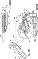
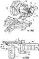
- a brushless motor such as the BLDC 30 described above can be used to the benefit of other types of tools, such as the sliding miter saw 200 shown in FIGS. 12(a) -(b).
- the saw 200 includes a saw assembly 202 supported by a slide assembly 206 on a base assembly 204 so that the saw assembly can translate across the working surface 205 of the base assembly.
- An arm assembly 208 supports the saw assembly on a bevel mount 210 that is slidably supported on the slide assembly 206 and is configured to allow the saw assembly to be oriented at a non-perpendicular angle relative to the work surface.
- the power tool 200 includes a motor M that projects laterally from the arm assembly 208 across the work surface.
- the power tool 200 suffers from the same drawbacks associated with the bulky and heavy conventional universal AC motor.
- the BLDC motor 30 may be incorporated into a drive train 215 disposed within a modified arm assembly 208 i , as shown in FIGS. 13(a) -(b).
- the drive train includes a spur gear 216 mounted to the output shaft 31 of the motor and in meshed engagement with a spur gear 217.
- the spur gear 217 includes an elongated shaft that is sized to extend from a motor position at the back of the arm assembly 208i to a position adjacent the drive shaft S of the saw blade.
- a pinion gear 219 is engaged to the end of the shaft 218 and is in meshed engagement with a bevel gear 220 that drives the shaft S.
- replacing the conventional motor with the BLDC 30 provides a more compact package for the power tool.
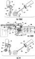
- the drive train 215 may be modified as shown in FIG. 14 to incorporate a cooling fan 228.
- a pulley wheel 224 may be engaged to the output shaft of the BLDC motor 30 inboard of the spur gear 26.
- the pulley wheel 224 drives a belt 226 that engages an opposite pulley wheel 227 to spin the fan 228.
- the pulley wheels 224, 227 can be sized to achieve a desired fan speed relative to the output speed of the BLDC motor 30.
- an arm assembly A which may be like the arm assembly 19" and gear train 55 shown in FIGS. 4(a) -(c), may be mounted to the base and mount assemblies B 1 - B 4 for several different types of miter saws.
- the arm assembly may support different saw assemblies.
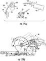
- a power tool 250 includes a saw blade 252 carried by an arm assembly 254 that is supported for angular adjustment and slide movement by a bevel mount 256 and a slide assembly 258.
- the arm assembly 254 may support a BLDC motor 30 laterally, as depicted in FIG. 15 , or within the arm assembly housing using one of the drive trains described herein.
- the tool 250 incorporates a handle assembly 260 that allows the handle to be swiveled left or right, as indicated by the arrow P.
- the handle assembly thus includes a housing 261 that forms a handle grip at one end and that includes a pivot portion 262 at the opposite end.
- the pivot portion engages a pivot mount 263 on the arm assembly 254 so that the housing can be manually swung from side-to-side.
- This handle assembly 260 thus allows the tool operator to find a comfortable gripping position for performing the cutting operation.
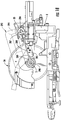
- a drive train 270 includes a hub 272 mounted to the output shaft 31 of a BLDC motor 30 , with a flexible shaft 273 engaged to the hub.
- a pinion gear 274 is fixed at the end of the flexible shaft to mesh with a bevel gear 275 that drives the saw blade shaft S.
- the flexible shaft allows the motor 30 to be offset from the remainder of the drive train, which permits an arm assembly 280 that is more compact.
- the use of the flexible shaft 273 allows the motor 30 to be disposed in a fixed portion 282 of the arm assembly while the flexible shaft 273 extends through a movable portion 281 of the assembly, as depicted in FIG. 17(d) .
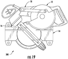
- the BLDC motor 30 may also be oriented directly on a pivot axis for an arm assembly in a power tool.
- an arm assembly 292 carries a saw assembly SA.
- the arm assembly includes a pivot hub 294 that is pivotably mounted to a base and mount assembly B.
- the drive motor 30 may be aligned along the pivot axis within the pivot hub 284.
- the drive train 285 includes a pinion and bevel gear arrangement 286/287 that drives a shaft 288 that extends between the pivot axis and the drive shaft S of the saw blade.
- a pinion and bevel gear arrangement 289/290 at the end of the shaft 288 transmits power to the blade shaft S.
- the reduced size of the BLDC motor also allows an entire miter saw to be folded into a compact configuration.
- a miter saw including a saw assembly 12, base assembly 14, mount assembly 16 and arm assembly 18 can be folded to fit within a carry case 300. Since the drive motor 30 is encased within the arm assembly in most of the above embodiments, the arm assembly can be pivoted to a "fold flat" position on top of the base assembly 14.
Landscapes
- Engineering & Computer Science (AREA)
- Mechanical Engineering (AREA)
- Sawing (AREA)
Claims (4)
- Gehrungssäge (10), umfassend:eine Basisanordnung (14);eine Sägenanordnung (12) umfassend ein Sägeblatt mit einer Antriebswelle (S), wobei die Sägenanordnung (12) an der Basisanordnung (14) durch eine Gehrungshalterung (16) getragen ist;eine Armanordnung (18'''), die die Sägeanordnung (12) mit der Gehrungshalterung (16) verbindet, wobei die Armanordnung ein Armgehäuse (19"') und einen Griff (20''') umfasst, der durch einen Bediener gegriffen werden kann, um die Bewegung der Sägeanordnung (12) bei Ausführen eines Schnittes zu steuern, wobei das Armgehäuse (19''') eine übersteigerte C-Form von ihrem Eingriff mit der Gehrungshalterung (16) zu dem Griff (20''') aufweist;ein Antriebsmotorgehäuse (103), das von dem C-förmigen Gehäuse (19''') nach innen hin zu der Antriebswelle (S) ragt, wobei die Armanordnung (18''') direkt über und fluchtend mit der Sägeanordnung (12) angeordnet ist, wobei das Antriebsmotorgehäuse (103) seitlich von dem Armgehäuse (19"') versetzt ist;einen bürstenlosen Gleichstrommotor, BLDC (brushless DC), (30), der eine Abtriebswelle (31) aufweist und in dem Motorgehäuse (103) gehalten ist, undeinen in dem Motorgehäuse (103) gehaltenen Antriebsstrang (95), wobei der Antriebsstrang (95) die Abtriebswelle (31) des BLDC-Motors (30) mit der Antriebswelle (S) wirkverbindet, wobei der Antriebsstrang (95) ein Ritzel (96) umfasst, das an der Abtriebswelle (31) des BLDC-Motors (30) gehalten ist, das in ein Kegelrad (97) eingreift, und wobei das Kegelrad eine zentrale Nabe (98) umfasst, die ein Stirnrad (99) stützt, das dann in ein Stirnrad (100) eingreift, das mit der Antriebswelle (S) des Sägeblatts in Eingriff ist.
- Gehrungssäge nach Anspruch 1, wobei:das Sägeblatt eine Betriebsdrehzahl aufweist;der BLDC-Motor (30) eine Leerlaufdrehzahl aufweist, die kleiner als die Betriebsdrehzahl ist; undder Antriebsstrang (95) ein Übersetzungsverhältnis aufweist, das dem Verhältnis der Betriebsdrehzahl des Sägeblatts zu der Leerlaufdrehzahl des BLDC entspricht.
- Gehrungssäge nach Anspruch 1, wobei sich die Abtriebswelle (31) des BLDC-Motors (30) über entgegengesetzte Enden des Motors (30) hinaus erstreckt, wobei ein Ende der Antriebswelle (S) mit dem Antriebsstrang (95) verbunden ist und das entgegengesetzte Ende der Antriebswelle (S) einen Radiallüfter trägt.
- Gehrungssäge nach Anspruch 1, wobei der Antriebsstrang (95) entlang einer Achse des Motorgehäuses (103) im Allgemeinen im rechten Winkel zu dem Armgehäuse (19"') ausgerichtet ist.
Applications Claiming Priority (2)
| Application Number | Priority Date | Filing Date | Title |
|---|---|---|---|
| US201361787115P | 2013-03-15 | 2013-03-15 | |
| PCT/US2014/024414 WO2014150859A1 (en) | 2013-03-15 | 2014-03-12 | Power tool with brushless drive motor |
Publications (3)
| Publication Number | Publication Date |
|---|---|
| EP2969332A1 EP2969332A1 (de) | 2016-01-20 |
| EP2969332A4 EP2969332A4 (de) | 2016-11-09 |
| EP2969332B1 true EP2969332B1 (de) | 2020-10-07 |
Family
ID=51580842
Family Applications (1)
| Application Number | Title | Priority Date | Filing Date |
|---|---|---|---|
| EP14771125.3A Not-in-force EP2969332B1 (de) | 2013-03-15 | 2014-03-12 | Gehrungssäge mit bürstenlosem antriebsmotor |
Country Status (2)
| Country | Link |
|---|---|
| EP (1) | EP2969332B1 (de) |
| WO (1) | WO2014150859A1 (de) |
Cited By (2)
| Publication number | Priority date | Publication date | Assignee | Title |
|---|---|---|---|---|
| US11837935B2 (en) | 2021-02-02 | 2023-12-05 | Black & Decker, Inc. | Canned brushless motor |
| US12186818B2 (en) | 2022-01-12 | 2025-01-07 | Makita Corporation | Sliding cutting machine |
Families Citing this family (11)
| Publication number | Priority date | Publication date | Assignee | Title |
|---|---|---|---|---|
| TWI569910B (zh) * | 2015-11-16 | 2017-02-11 | 力山工業股份有限公司 | 可收折的鋸切機 |
| US10780510B2 (en) | 2014-09-10 | 2020-09-22 | Rexon Industrial Corp., Ltd. | Foldable miter saws and foldable method of miter saw |
| TWI535512B (zh) * | 2014-09-12 | 2016-06-01 | 力山工業股份有限公司 | 可折疊的鋸切機及鋸切機的折疊方法 |
| EP4201565A3 (de) | 2015-02-25 | 2023-09-20 | Milwaukee Electric Tool Corporation | Gehrungssäge |
| JP6534543B2 (ja) * | 2015-03-17 | 2019-06-26 | 株式会社マキタ | 切断機 |
| WO2018053976A1 (zh) | 2016-09-20 | 2018-03-29 | 正阳实业投资有限公司 | 复式锯 |
| JP7009189B2 (ja) * | 2017-12-06 | 2022-01-25 | 株式会社マキタ | 切断機 |
| US11413692B2 (en) | 2019-09-26 | 2022-08-16 | Robert Bosch Power Tools GmbH | Saw drivetrain with a chain drive and gear train |
| US12186817B2 (en) * | 2020-12-02 | 2025-01-07 | Makita Corporation | Sliding cutting machine |
| JP7675597B2 (ja) * | 2021-08-26 | 2025-05-13 | 株式会社マキタ | 動力工具 |
| JP7762576B2 (ja) | 2022-01-07 | 2025-10-30 | 株式会社マキタ | 電動作業機 |
Citations (2)
| Publication number | Priority date | Publication date | Assignee | Title |
|---|---|---|---|---|
| US20030089511A1 (en) * | 2001-11-12 | 2003-05-15 | Yukio Tsuneda | Electric tool |
| US20080289843A1 (en) * | 2006-11-10 | 2008-11-27 | Joel Townsan | Electric hand screwdriver with adjustable head |
Family Cites Families (10)
| Publication number | Priority date | Publication date | Assignee | Title |
|---|---|---|---|---|
| JP2573057B2 (ja) * | 1989-07-07 | 1997-01-16 | 株式会社マキタ | 卓上丸鋸盤 |
| EP0570904B1 (de) * | 1992-05-22 | 1997-08-13 | Makita Corporation | Gehrungssäge |
| JPH11300520A (ja) * | 1998-04-24 | 1999-11-02 | Higuchi Densetsu Kk | 電動パイプカッタ− |
| EP1604764A1 (de) * | 2001-02-08 | 2005-12-14 | BLACK & DECKER INC. | Blattklingenschutz für eine Gehrungssäge |
| JP2004007869A (ja) * | 2002-05-30 | 2004-01-08 | Makita Corp | 電動工具用ブラシレスモータ |
| US7059228B2 (en) * | 2003-09-11 | 2006-06-13 | Chin-Chin Chang | Hand-controlled circular saw |
| CN100349679C (zh) * | 2003-10-23 | 2007-11-21 | 苏州宝时得电动工具有限公司 | 斜切割机 |
| US8302519B2 (en) * | 2008-12-31 | 2012-11-06 | Techtronic Power Tools Technology Limited | Hand-held power tool |
| JP2010274392A (ja) * | 2009-05-29 | 2010-12-09 | Hitachi Koki Co Ltd | 卓上切断機 |
| US8631733B2 (en) * | 2009-11-06 | 2014-01-21 | Hitachi Koki Co., Ltd. | Miter saw |
-
2014
- 2014-03-12 EP EP14771125.3A patent/EP2969332B1/de not_active Not-in-force
- 2014-03-12 WO PCT/US2014/024414 patent/WO2014150859A1/en not_active Ceased
Patent Citations (2)
| Publication number | Priority date | Publication date | Assignee | Title |
|---|---|---|---|---|
| US20030089511A1 (en) * | 2001-11-12 | 2003-05-15 | Yukio Tsuneda | Electric tool |
| US20080289843A1 (en) * | 2006-11-10 | 2008-11-27 | Joel Townsan | Electric hand screwdriver with adjustable head |
Cited By (7)
| Publication number | Priority date | Publication date | Assignee | Title |
|---|---|---|---|---|
| US11837935B2 (en) | 2021-02-02 | 2023-12-05 | Black & Decker, Inc. | Canned brushless motor |
| US11855521B2 (en) | 2021-02-02 | 2023-12-26 | Black & Decker, Inc. | Brushless DC motor for a body-grip power tool |
| US11870316B2 (en) | 2021-02-02 | 2024-01-09 | Black & Decker, Inc. | Brushless motor including a nested bearing bridge |
| US11876424B2 (en) | 2021-02-02 | 2024-01-16 | Black & Decker Inc. | Compact brushless motor including in-line terminals |
| US11955863B2 (en) | 2021-02-02 | 2024-04-09 | Black & Decker Inc. | Circuit board assembly for compact brushless motor |
| US12261497B2 (en) | 2021-02-02 | 2025-03-25 | Black & Decker Inc. | High-power motor for a body-grip power tool |
| US12186818B2 (en) | 2022-01-12 | 2025-01-07 | Makita Corporation | Sliding cutting machine |
Also Published As
| Publication number | Publication date |
|---|---|
| EP2969332A4 (de) | 2016-11-09 |
| EP2969332A1 (de) | 2016-01-20 |
| WO2014150859A1 (en) | 2014-09-25 |
Similar Documents
| Publication | Publication Date | Title |
|---|---|---|
| EP2969332B1 (de) | Gehrungssäge mit bürstenlosem antriebsmotor | |
| EP2694260B1 (de) | Stichsäge | |
| US9364906B2 (en) | Power tool with high-speed electric motor | |
| US20130333228A1 (en) | Cutting tool | |
| EP3388177B1 (de) | Handschneidwerkzeug | |
| US10369640B2 (en) | Miter saw including a chain drive | |
| US5027518A (en) | Battery operated coping saw | |
| US4949464A (en) | Battery operated coping saw | |
| US12070809B2 (en) | Band saw | |
| WO1993003894A1 (en) | Portable electric cutting and scoring saw | |
| US12390868B2 (en) | Electric working machine | |
| CN118216312A (zh) | 一种割草机折叠式底盘 | |
| CN104249190B (zh) | 管道切割机 | |
| CN213591924U (zh) | 一种往复锯机头及安装有该往复锯机头的角磨机 | |
| US2858703A (en) | Power-driven hand unit for rotary and reciprocating tools | |
| US20250050436A1 (en) | Miter saw with multiple motors | |
| CN2912876Y (zh) | 斜切割机 | |
| CN205702678U (zh) | 电圆锯 | |
| CN110014190A (zh) | 便携式切割机 | |
| TWI878350B (zh) | 具有鏈傳動及齒輪系的鋸傳動系統和斜切鋸傳動系統 | |
| CN223431023U (zh) | 电圆锯 | |
| CN217572309U (zh) | 一种便捷式角磨机 | |
| CA2011742A1 (en) | Battery operated coping saw | |
| TWM469973U (zh) | 鋸切機具之鋸片驅動機構 | |
| CN2065541U (zh) | 木工手电锯 |
Legal Events
| Date | Code | Title | Description |
|---|---|---|---|
| PUAI | Public reference made under article 153(3) epc to a published international application that has entered the european phase |
Free format text: ORIGINAL CODE: 0009012 |
|
| 17P | Request for examination filed |
Effective date: 20151015 |
|
| AK | Designated contracting states |
Kind code of ref document: A1 Designated state(s): AL AT BE BG CH CY CZ DE DK EE ES FI FR GB GR HR HU IE IS IT LI LT LU LV MC MK MT NL NO PL PT RO RS SE SI SK SM TR |
|
| AX | Request for extension of the european patent |
Extension state: BA ME |
|
| RAP1 | Party data changed (applicant data changed or rights of an application transferred) |
Owner name: ROBERT BOSCH GMBH |
|
| DAX | Request for extension of the european patent (deleted) | ||
| A4 | Supplementary search report drawn up and despatched |
Effective date: 20161010 |
|
| RIC1 | Information provided on ipc code assigned before grant |
Ipc: B23D 45/04 20060101AFI20161004BHEP Ipc: B23D 47/12 20060101ALI20161004BHEP |
|
| STAA | Information on the status of an ep patent application or granted ep patent |
Free format text: STATUS: EXAMINATION IS IN PROGRESS |
|
| 17Q | First examination report despatched |
Effective date: 20171205 |
|
| RAP1 | Party data changed (applicant data changed or rights of an application transferred) |
Owner name: ROBERT BOSCH GMBH |
|
| GRAP | Despatch of communication of intention to grant a patent |
Free format text: ORIGINAL CODE: EPIDOSNIGR1 |
|
| STAA | Information on the status of an ep patent application or granted ep patent |
Free format text: STATUS: GRANT OF PATENT IS INTENDED |
|
| INTG | Intention to grant announced |
Effective date: 20200511 |
|
| GRAS | Grant fee paid |
Free format text: ORIGINAL CODE: EPIDOSNIGR3 |
|
| GRAA | (expected) grant |
Free format text: ORIGINAL CODE: 0009210 |
|
| STAA | Information on the status of an ep patent application or granted ep patent |
Free format text: STATUS: THE PATENT HAS BEEN GRANTED |
|
| AK | Designated contracting states |
Kind code of ref document: B1 Designated state(s): AL AT BE BG CH CY CZ DE DK EE ES FI FR GB GR HR HU IE IS IT LI LT LU LV MC MK MT NL NO PL PT RO RS SE SI SK SM TR |
|
| REG | Reference to a national code |
Ref country code: GB Ref legal event code: FG4D |
|
| REG | Reference to a national code |
Ref country code: CH Ref legal event code: EP Ref country code: AT Ref legal event code: REF Ref document number: 1320611 Country of ref document: AT Kind code of ref document: T Effective date: 20201015 |
|
| REG | Reference to a national code |
Ref country code: IE Ref legal event code: FG4D |
|
| REG | Reference to a national code |
Ref country code: DE Ref legal event code: R096 Ref document number: 602014071019 Country of ref document: DE |
|
| REG | Reference to a national code |
Ref country code: NL Ref legal event code: MP Effective date: 20201007 |
|
| REG | Reference to a national code |
Ref country code: AT Ref legal event code: MK05 Ref document number: 1320611 Country of ref document: AT Kind code of ref document: T Effective date: 20201007 |
|
| PG25 | Lapsed in a contracting state [announced via postgrant information from national office to epo] |
Ref country code: GR Free format text: LAPSE BECAUSE OF FAILURE TO SUBMIT A TRANSLATION OF THE DESCRIPTION OR TO PAY THE FEE WITHIN THE PRESCRIBED TIME-LIMIT Effective date: 20210108 Ref country code: PT Free format text: LAPSE BECAUSE OF FAILURE TO SUBMIT A TRANSLATION OF THE DESCRIPTION OR TO PAY THE FEE WITHIN THE PRESCRIBED TIME-LIMIT Effective date: 20210208 Ref country code: NL Free format text: LAPSE BECAUSE OF FAILURE TO SUBMIT A TRANSLATION OF THE DESCRIPTION OR TO PAY THE FEE WITHIN THE PRESCRIBED TIME-LIMIT Effective date: 20201007 Ref country code: NO Free format text: LAPSE BECAUSE OF FAILURE TO SUBMIT A TRANSLATION OF THE DESCRIPTION OR TO PAY THE FEE WITHIN THE PRESCRIBED TIME-LIMIT Effective date: 20210107 Ref country code: RS Free format text: LAPSE BECAUSE OF FAILURE TO SUBMIT A TRANSLATION OF THE DESCRIPTION OR TO PAY THE FEE WITHIN THE PRESCRIBED TIME-LIMIT Effective date: 20201007 Ref country code: FI Free format text: LAPSE BECAUSE OF FAILURE TO SUBMIT A TRANSLATION OF THE DESCRIPTION OR TO PAY THE FEE WITHIN THE PRESCRIBED TIME-LIMIT Effective date: 20201007 |
|
| REG | Reference to a national code |
Ref country code: LT Ref legal event code: MG4D |
|
| PG25 | Lapsed in a contracting state [announced via postgrant information from national office to epo] |
Ref country code: LV Free format text: LAPSE BECAUSE OF FAILURE TO SUBMIT A TRANSLATION OF THE DESCRIPTION OR TO PAY THE FEE WITHIN THE PRESCRIBED TIME-LIMIT Effective date: 20201007 Ref country code: SE Free format text: LAPSE BECAUSE OF FAILURE TO SUBMIT A TRANSLATION OF THE DESCRIPTION OR TO PAY THE FEE WITHIN THE PRESCRIBED TIME-LIMIT Effective date: 20201007 Ref country code: PL Free format text: LAPSE BECAUSE OF FAILURE TO SUBMIT A TRANSLATION OF THE DESCRIPTION OR TO PAY THE FEE WITHIN THE PRESCRIBED TIME-LIMIT Effective date: 20201007 Ref country code: IS Free format text: LAPSE BECAUSE OF FAILURE TO SUBMIT A TRANSLATION OF THE DESCRIPTION OR TO PAY THE FEE WITHIN THE PRESCRIBED TIME-LIMIT Effective date: 20210207 Ref country code: BG Free format text: LAPSE BECAUSE OF FAILURE TO SUBMIT A TRANSLATION OF THE DESCRIPTION OR TO PAY THE FEE WITHIN THE PRESCRIBED TIME-LIMIT Effective date: 20210107 Ref country code: AT Free format text: LAPSE BECAUSE OF FAILURE TO SUBMIT A TRANSLATION OF THE DESCRIPTION OR TO PAY THE FEE WITHIN THE PRESCRIBED TIME-LIMIT Effective date: 20201007 Ref country code: ES Free format text: LAPSE BECAUSE OF FAILURE TO SUBMIT A TRANSLATION OF THE DESCRIPTION OR TO PAY THE FEE WITHIN THE PRESCRIBED TIME-LIMIT Effective date: 20201007 |
|
| PG25 | Lapsed in a contracting state [announced via postgrant information from national office to epo] |
Ref country code: HR Free format text: LAPSE BECAUSE OF FAILURE TO SUBMIT A TRANSLATION OF THE DESCRIPTION OR TO PAY THE FEE WITHIN THE PRESCRIBED TIME-LIMIT Effective date: 20201007 |
|
| REG | Reference to a national code |
Ref country code: DE Ref legal event code: R097 Ref document number: 602014071019 Country of ref document: DE |
|
| PG25 | Lapsed in a contracting state [announced via postgrant information from national office to epo] |
Ref country code: CZ Free format text: LAPSE BECAUSE OF FAILURE TO SUBMIT A TRANSLATION OF THE DESCRIPTION OR TO PAY THE FEE WITHIN THE PRESCRIBED TIME-LIMIT Effective date: 20201007 Ref country code: EE Free format text: LAPSE BECAUSE OF FAILURE TO SUBMIT A TRANSLATION OF THE DESCRIPTION OR TO PAY THE FEE WITHIN THE PRESCRIBED TIME-LIMIT Effective date: 20201007 Ref country code: SM Free format text: LAPSE BECAUSE OF FAILURE TO SUBMIT A TRANSLATION OF THE DESCRIPTION OR TO PAY THE FEE WITHIN THE PRESCRIBED TIME-LIMIT Effective date: 20201007 Ref country code: LT Free format text: LAPSE BECAUSE OF FAILURE TO SUBMIT A TRANSLATION OF THE DESCRIPTION OR TO PAY THE FEE WITHIN THE PRESCRIBED TIME-LIMIT Effective date: 20201007 Ref country code: SK Free format text: LAPSE BECAUSE OF FAILURE TO SUBMIT A TRANSLATION OF THE DESCRIPTION OR TO PAY THE FEE WITHIN THE PRESCRIBED TIME-LIMIT Effective date: 20201007 Ref country code: RO Free format text: LAPSE BECAUSE OF FAILURE TO SUBMIT A TRANSLATION OF THE DESCRIPTION OR TO PAY THE FEE WITHIN THE PRESCRIBED TIME-LIMIT Effective date: 20201007 |
|
| PLBE | No opposition filed within time limit |
Free format text: ORIGINAL CODE: 0009261 |
|
| STAA | Information on the status of an ep patent application or granted ep patent |
Free format text: STATUS: NO OPPOSITION FILED WITHIN TIME LIMIT |
|
| PG25 | Lapsed in a contracting state [announced via postgrant information from national office to epo] |
Ref country code: DK Free format text: LAPSE BECAUSE OF FAILURE TO SUBMIT A TRANSLATION OF THE DESCRIPTION OR TO PAY THE FEE WITHIN THE PRESCRIBED TIME-LIMIT Effective date: 20201007 |
|
| 26N | No opposition filed |
Effective date: 20210708 |
|
| PG25 | Lapsed in a contracting state [announced via postgrant information from national office to epo] |
Ref country code: AL Free format text: LAPSE BECAUSE OF FAILURE TO SUBMIT A TRANSLATION OF THE DESCRIPTION OR TO PAY THE FEE WITHIN THE PRESCRIBED TIME-LIMIT Effective date: 20201007 Ref country code: MC Free format text: LAPSE BECAUSE OF FAILURE TO SUBMIT A TRANSLATION OF THE DESCRIPTION OR TO PAY THE FEE WITHIN THE PRESCRIBED TIME-LIMIT Effective date: 20201007 Ref country code: IT Free format text: LAPSE BECAUSE OF FAILURE TO SUBMIT A TRANSLATION OF THE DESCRIPTION OR TO PAY THE FEE WITHIN THE PRESCRIBED TIME-LIMIT Effective date: 20201007 |
|
| REG | Reference to a national code |
Ref country code: CH Ref legal event code: PL |
|
| PG25 | Lapsed in a contracting state [announced via postgrant information from national office to epo] |
Ref country code: SI Free format text: LAPSE BECAUSE OF FAILURE TO SUBMIT A TRANSLATION OF THE DESCRIPTION OR TO PAY THE FEE WITHIN THE PRESCRIBED TIME-LIMIT Effective date: 20201007 |
|
| REG | Reference to a national code |
Ref country code: BE Ref legal event code: MM Effective date: 20210331 |
|
| PG25 | Lapsed in a contracting state [announced via postgrant information from national office to epo] |
Ref country code: CH Free format text: LAPSE BECAUSE OF NON-PAYMENT OF DUE FEES Effective date: 20210331 Ref country code: LI Free format text: LAPSE BECAUSE OF NON-PAYMENT OF DUE FEES Effective date: 20210331 Ref country code: LU Free format text: LAPSE BECAUSE OF NON-PAYMENT OF DUE FEES Effective date: 20210312 Ref country code: IE Free format text: LAPSE BECAUSE OF NON-PAYMENT OF DUE FEES Effective date: 20210312 |
|
| PG25 | Lapsed in a contracting state [announced via postgrant information from national office to epo] |
Ref country code: IS Free format text: LAPSE BECAUSE OF FAILURE TO SUBMIT A TRANSLATION OF THE DESCRIPTION OR TO PAY THE FEE WITHIN THE PRESCRIBED TIME-LIMIT Effective date: 20210207 |
|
| PG25 | Lapsed in a contracting state [announced via postgrant information from national office to epo] |
Ref country code: BE Free format text: LAPSE BECAUSE OF NON-PAYMENT OF DUE FEES Effective date: 20210331 |
|
| PG25 | Lapsed in a contracting state [announced via postgrant information from national office to epo] |
Ref country code: HU Free format text: LAPSE BECAUSE OF FAILURE TO SUBMIT A TRANSLATION OF THE DESCRIPTION OR TO PAY THE FEE WITHIN THE PRESCRIBED TIME-LIMIT; INVALID AB INITIO Effective date: 20140312 |
|
| PG25 | Lapsed in a contracting state [announced via postgrant information from national office to epo] |
Ref country code: CY Free format text: LAPSE BECAUSE OF FAILURE TO SUBMIT A TRANSLATION OF THE DESCRIPTION OR TO PAY THE FEE WITHIN THE PRESCRIBED TIME-LIMIT Effective date: 20201007 |
|
| PG25 | Lapsed in a contracting state [announced via postgrant information from national office to epo] |
Ref country code: MK Free format text: LAPSE BECAUSE OF FAILURE TO SUBMIT A TRANSLATION OF THE DESCRIPTION OR TO PAY THE FEE WITHIN THE PRESCRIBED TIME-LIMIT Effective date: 20201007 |
|
| PGFP | Annual fee paid to national office [announced via postgrant information from national office to epo] |
Ref country code: GB Payment date: 20240322 Year of fee payment: 11 |
|
| PGFP | Annual fee paid to national office [announced via postgrant information from national office to epo] |
Ref country code: FR Payment date: 20240320 Year of fee payment: 11 |
|
| PG25 | Lapsed in a contracting state [announced via postgrant information from national office to epo] |
Ref country code: TR Free format text: LAPSE BECAUSE OF FAILURE TO SUBMIT A TRANSLATION OF THE DESCRIPTION OR TO PAY THE FEE WITHIN THE PRESCRIBED TIME-LIMIT Effective date: 20201007 |
|
| PGFP | Annual fee paid to national office [announced via postgrant information from national office to epo] |
Ref country code: DE Payment date: 20240527 Year of fee payment: 11 |
|
| PG25 | Lapsed in a contracting state [announced via postgrant information from national office to epo] |
Ref country code: MT Free format text: LAPSE BECAUSE OF FAILURE TO SUBMIT A TRANSLATION OF THE DESCRIPTION OR TO PAY THE FEE WITHIN THE PRESCRIBED TIME-LIMIT Effective date: 20201007 |
|
| REG | Reference to a national code |
Ref country code: DE Ref legal event code: R119 Ref document number: 602014071019 Country of ref document: DE |
|
| GBPC | Gb: european patent ceased through non-payment of renewal fee |
Effective date: 20250312 |
|
| PG25 | Lapsed in a contracting state [announced via postgrant information from national office to epo] |
Ref country code: DE Free format text: LAPSE BECAUSE OF NON-PAYMENT OF DUE FEES Effective date: 20251001 |
|
| PG25 | Lapsed in a contracting state [announced via postgrant information from national office to epo] |
Ref country code: GB Free format text: LAPSE BECAUSE OF NON-PAYMENT OF DUE FEES Effective date: 20250312 |
|
| PG25 | Lapsed in a contracting state [announced via postgrant information from national office to epo] |
Ref country code: FR Free format text: LAPSE BECAUSE OF NON-PAYMENT OF DUE FEES Effective date: 20250331 |