EP2967930B1 - Anti-migration tissue anchoring system for a fully covered stent - Google Patents
Anti-migration tissue anchoring system for a fully covered stent Download PDFInfo
- Publication number
- EP2967930B1 EP2967930B1 EP14712175.0A EP14712175A EP2967930B1 EP 2967930 B1 EP2967930 B1 EP 2967930B1 EP 14712175 A EP14712175 A EP 14712175A EP 2967930 B1 EP2967930 B1 EP 2967930B1
- Authority
- EP
- European Patent Office
- Prior art keywords
- anchor
- stent
- cover
- region
- circumferential band
- Prior art date
- Legal status (The legal status is an assumption and is not a legal conclusion. Google has not performed a legal analysis and makes no representation as to the accuracy of the status listed.)
- Active
Links
- 238000013508 migration Methods 0.000 title claims description 20
- 238000004873 anchoring Methods 0.000 title description 15
- 239000000463 material Substances 0.000 claims description 35
- 238000000034 method Methods 0.000 claims description 20
- 238000003698 laser cutting Methods 0.000 claims description 5
- 229920002635 polyurethane Polymers 0.000 claims description 4
- 239000004814 polyurethane Substances 0.000 claims description 4
- 238000009998 heat setting Methods 0.000 claims description 3
- 229920001296 polysiloxane Polymers 0.000 claims description 3
- 238000004519 manufacturing process Methods 0.000 claims description 2
- 210000001519 tissue Anatomy 0.000 description 18
- 239000003814 drug Substances 0.000 description 12
- 230000001419 dependent effect Effects 0.000 description 11
- 229940124597 therapeutic agent Drugs 0.000 description 11
- 239000003795 chemical substances by application Substances 0.000 description 7
- 238000000576 coating method Methods 0.000 description 7
- 230000005284 excitation Effects 0.000 description 6
- 230000005012 migration Effects 0.000 description 6
- 239000011248 coating agent Substances 0.000 description 5
- 230000002068 genetic effect Effects 0.000 description 5
- 238000002513 implantation Methods 0.000 description 5
- 229920000642 polymer Polymers 0.000 description 5
- 239000004593 Epoxy Substances 0.000 description 4
- 229910045601 alloy Inorganic materials 0.000 description 4
- 239000000956 alloy Substances 0.000 description 4
- 229910052751 metal Inorganic materials 0.000 description 4
- 239000002184 metal Substances 0.000 description 4
- 230000008467 tissue growth Effects 0.000 description 4
- 230000001131 transforming effect Effects 0.000 description 4
- 230000007704 transition Effects 0.000 description 4
- 230000001413 cellular effect Effects 0.000 description 3
- 150000002739 metals Chemical class 0.000 description 3
- 229910001000 nickel titanium Inorganic materials 0.000 description 3
- -1 Elgiloy and Phynox Chemical class 0.000 description 2
- HTTJABKRGRZYRN-UHFFFAOYSA-N Heparin Chemical compound OC1C(NC(=O)C)C(O)OC(COS(O)(=O)=O)C1OC1C(OS(O)(=O)=O)C(O)C(OC2C(C(OS(O)(=O)=O)C(OC3C(C(O)C(O)C(O3)C(O)=O)OS(O)(=O)=O)C(CO)O2)NS(O)(=O)=O)C(C(O)=O)O1 HTTJABKRGRZYRN-UHFFFAOYSA-N 0.000 description 2
- 229920000954 Polyglycolide Polymers 0.000 description 2
- 239000004793 Polystyrene Substances 0.000 description 2
- WYTGDNHDOZPMIW-RCBQFDQVSA-N alstonine Natural products C1=CC2=C3C=CC=CC3=NC2=C2N1C[C@H]1[C@H](C)OC=C(C(=O)OC)[C@H]1C2 WYTGDNHDOZPMIW-RCBQFDQVSA-N 0.000 description 2
- 230000015572 biosynthetic process Effects 0.000 description 2
- 210000004027 cell Anatomy 0.000 description 2
- 238000010329 laser etching Methods 0.000 description 2
- HLXZNVUGXRDIFK-UHFFFAOYSA-N nickel titanium Chemical compound [Ti].[Ti].[Ti].[Ti].[Ti].[Ti].[Ti].[Ti].[Ti].[Ti].[Ti].[Ni].[Ni].[Ni].[Ni].[Ni].[Ni].[Ni].[Ni].[Ni].[Ni].[Ni].[Ni].[Ni].[Ni] HLXZNVUGXRDIFK-UHFFFAOYSA-N 0.000 description 2
- BASFCYQUMIYNBI-UHFFFAOYSA-N platinum Chemical compound [Pt] BASFCYQUMIYNBI-UHFFFAOYSA-N 0.000 description 2
- 239000004633 polyglycolic acid Substances 0.000 description 2
- 229920002223 polystyrene Polymers 0.000 description 2
- 102000004169 proteins and genes Human genes 0.000 description 2
- 108090000623 proteins and genes Proteins 0.000 description 2
- 239000012781 shape memory material Substances 0.000 description 2
- 229920002379 silicone rubber Polymers 0.000 description 2
- 229920000428 triblock copolymer Polymers 0.000 description 2
- 102000008186 Collagen Human genes 0.000 description 1
- 108010035532 Collagen Proteins 0.000 description 1
- 206010063560 Excessive granulation tissue Diseases 0.000 description 1
- 102000003693 Hedgehog Proteins Human genes 0.000 description 1
- 108090000031 Hedgehog Proteins Proteins 0.000 description 1
- 206010061218 Inflammation Diseases 0.000 description 1
- 206010028980 Neoplasm Diseases 0.000 description 1
- 229930012538 Paclitaxel Natural products 0.000 description 1
- 229920003171 Poly (ethylene oxide) Polymers 0.000 description 1
- 229910000639 Spring steel Inorganic materials 0.000 description 1
- RTAQQCXQSZGOHL-UHFFFAOYSA-N Titanium Chemical compound [Ti] RTAQQCXQSZGOHL-UHFFFAOYSA-N 0.000 description 1
- HZEWFHLRYVTOIW-UHFFFAOYSA-N [Ti].[Ni] Chemical compound [Ti].[Ni] HZEWFHLRYVTOIW-UHFFFAOYSA-N 0.000 description 1
- 239000002253 acid Substances 0.000 description 1
- 239000000853 adhesive Substances 0.000 description 1
- 230000001070 adhesive effect Effects 0.000 description 1
- 239000000560 biocompatible material Substances 0.000 description 1
- 229920002988 biodegradable polymer Polymers 0.000 description 1
- 239000004621 biodegradable polymer Substances 0.000 description 1
- 230000031018 biological processes and functions Effects 0.000 description 1
- 230000015556 catabolic process Effects 0.000 description 1
- 230000010261 cell growth Effects 0.000 description 1
- 239000000788 chromium alloy Substances 0.000 description 1
- 229920001436 collagen Polymers 0.000 description 1
- 239000002131 composite material Substances 0.000 description 1
- 150000001875 compounds Chemical class 0.000 description 1
- 229920001577 copolymer Polymers 0.000 description 1
- 210000004351 coronary vessel Anatomy 0.000 description 1
- 230000002596 correlated effect Effects 0.000 description 1
- 238000000354 decomposition reaction Methods 0.000 description 1
- 238000003618 dip coating Methods 0.000 description 1
- 201000010099 disease Diseases 0.000 description 1
- 208000037265 diseases, disorders, signs and symptoms Diseases 0.000 description 1
- 229940079593 drug Drugs 0.000 description 1
- 229910000701 elgiloys (Co-Cr-Ni Alloy) Inorganic materials 0.000 description 1
- 229920000295 expanded polytetrafluoroethylene Polymers 0.000 description 1
- 239000003527 fibrinolytic agent Substances 0.000 description 1
- 210000001035 gastrointestinal tract Anatomy 0.000 description 1
- PCHJSUWPFVWCPO-UHFFFAOYSA-N gold Chemical compound [Au] PCHJSUWPFVWCPO-UHFFFAOYSA-N 0.000 description 1
- 229910052737 gold Inorganic materials 0.000 description 1
- 239000010931 gold Substances 0.000 description 1
- 210000001126 granulation tissue Anatomy 0.000 description 1
- 230000037313 granulation tissue formation Effects 0.000 description 1
- 239000003102 growth factor Substances 0.000 description 1
- 239000007952 growth promoter Substances 0.000 description 1
- 229960002897 heparin Drugs 0.000 description 1
- 229920000669 heparin Polymers 0.000 description 1
- 239000002628 heparin derivative Substances 0.000 description 1
- 238000003384 imaging method Methods 0.000 description 1
- 230000001939 inductive effect Effects 0.000 description 1
- 230000004054 inflammatory process Effects 0.000 description 1
- 239000003112 inhibitor Substances 0.000 description 1
- 238000005304 joining Methods 0.000 description 1
- 230000007246 mechanism Effects 0.000 description 1
- 210000003101 oviduct Anatomy 0.000 description 1
- 229960001592 paclitaxel Drugs 0.000 description 1
- 230000037361 pathway Effects 0.000 description 1
- 239000000825 pharmaceutical preparation Substances 0.000 description 1
- 229940127557 pharmaceutical product Drugs 0.000 description 1
- 229910052697 platinum Inorganic materials 0.000 description 1
- HWLDNSXPUQTBOD-UHFFFAOYSA-N platinum-iridium alloy Chemical class [Ir].[Pt] HWLDNSXPUQTBOD-UHFFFAOYSA-N 0.000 description 1
- 229920000747 poly(lactic acid) Polymers 0.000 description 1
- 229920001610 polycaprolactone Polymers 0.000 description 1
- 239000004632 polycaprolactone Substances 0.000 description 1
- 229920000515 polycarbonate Polymers 0.000 description 1
- 239000004417 polycarbonate Substances 0.000 description 1
- 229920000728 polyester Polymers 0.000 description 1
- 239000004626 polylactic acid Substances 0.000 description 1
- 238000004080 punching Methods 0.000 description 1
- 238000005096 rolling process Methods 0.000 description 1
- 239000004945 silicone rubber Substances 0.000 description 1
- 238000005507 spraying Methods 0.000 description 1
- 229910001220 stainless steel Inorganic materials 0.000 description 1
- 239000010935 stainless steel Substances 0.000 description 1
- 239000000758 substrate Substances 0.000 description 1
- 208000024891 symptom Diseases 0.000 description 1
- 229910052715 tantalum Inorganic materials 0.000 description 1
- GUVRBAGPIYLISA-UHFFFAOYSA-N tantalum atom Chemical compound [Ta] GUVRBAGPIYLISA-UHFFFAOYSA-N 0.000 description 1
- RCINICONZNJXQF-MZXODVADSA-N taxol Chemical compound O([C@@H]1[C@@]2(C[C@@H](C(C)=C(C2(C)C)[C@H](C([C@]2(C)[C@@H](O)C[C@H]3OC[C@]3([C@H]21)OC(C)=O)=O)OC(=O)C)OC(=O)[C@H](O)[C@@H](NC(=O)C=1C=CC=CC=1)C=1C=CC=CC=1)O)C(=O)C1=CC=CC=C1 RCINICONZNJXQF-MZXODVADSA-N 0.000 description 1
- 229910052719 titanium Inorganic materials 0.000 description 1
- 239000010936 titanium Substances 0.000 description 1
- WFKWXMTUELFFGS-UHFFFAOYSA-N tungsten Chemical compound [W] WFKWXMTUELFFGS-UHFFFAOYSA-N 0.000 description 1
- 239000010937 tungsten Substances 0.000 description 1
- 229910052721 tungsten Inorganic materials 0.000 description 1
- 238000002604 ultrasonography Methods 0.000 description 1
- 210000001635 urinary tract Anatomy 0.000 description 1
- 230000002792 vascular Effects 0.000 description 1
- 210000005167 vascular cell Anatomy 0.000 description 1
Images


Classifications
-
- A—HUMAN NECESSITIES
- A61—MEDICAL OR VETERINARY SCIENCE; HYGIENE
- A61F—FILTERS IMPLANTABLE INTO BLOOD VESSELS; PROSTHESES; DEVICES PROVIDING PATENCY TO, OR PREVENTING COLLAPSING OF, TUBULAR STRUCTURES OF THE BODY, e.g. STENTS; ORTHOPAEDIC, NURSING OR CONTRACEPTIVE DEVICES; FOMENTATION; TREATMENT OR PROTECTION OF EYES OR EARS; BANDAGES, DRESSINGS OR ABSORBENT PADS; FIRST-AID KITS
- A61F2/00—Filters implantable into blood vessels; Prostheses, i.e. artificial substitutes or replacements for parts of the body; Appliances for connecting them with the body; Devices providing patency to, or preventing collapsing of, tubular structures of the body, e.g. stents
- A61F2/82—Devices providing patency to, or preventing collapsing of, tubular structures of the body, e.g. stents
- A61F2/848—Devices providing patency to, or preventing collapsing of, tubular structures of the body, e.g. stents having means for fixation to the vessel wall, e.g. barbs
-
- A—HUMAN NECESSITIES
- A61—MEDICAL OR VETERINARY SCIENCE; HYGIENE
- A61F—FILTERS IMPLANTABLE INTO BLOOD VESSELS; PROSTHESES; DEVICES PROVIDING PATENCY TO, OR PREVENTING COLLAPSING OF, TUBULAR STRUCTURES OF THE BODY, e.g. STENTS; ORTHOPAEDIC, NURSING OR CONTRACEPTIVE DEVICES; FOMENTATION; TREATMENT OR PROTECTION OF EYES OR EARS; BANDAGES, DRESSINGS OR ABSORBENT PADS; FIRST-AID KITS
- A61F2/00—Filters implantable into blood vessels; Prostheses, i.e. artificial substitutes or replacements for parts of the body; Appliances for connecting them with the body; Devices providing patency to, or preventing collapsing of, tubular structures of the body, e.g. stents
- A61F2/82—Devices providing patency to, or preventing collapsing of, tubular structures of the body, e.g. stents
- A61F2/86—Stents in a form characterised by the wire-like elements; Stents in the form characterised by a net-like or mesh-like structure
- A61F2/90—Stents in a form characterised by the wire-like elements; Stents in the form characterised by a net-like or mesh-like structure characterised by a net-like or mesh-like structure
- A61F2/91—Stents in a form characterised by the wire-like elements; Stents in the form characterised by a net-like or mesh-like structure characterised by a net-like or mesh-like structure made from perforated sheet material or tubes, e.g. perforated by laser cuts or etched holes
- A61F2/915—Stents in a form characterised by the wire-like elements; Stents in the form characterised by a net-like or mesh-like structure characterised by a net-like or mesh-like structure made from perforated sheet material or tubes, e.g. perforated by laser cuts or etched holes with bands having a meander structure, adjacent bands being connected to each other
-
- A—HUMAN NECESSITIES
- A61—MEDICAL OR VETERINARY SCIENCE; HYGIENE
- A61F—FILTERS IMPLANTABLE INTO BLOOD VESSELS; PROSTHESES; DEVICES PROVIDING PATENCY TO, OR PREVENTING COLLAPSING OF, TUBULAR STRUCTURES OF THE BODY, e.g. STENTS; ORTHOPAEDIC, NURSING OR CONTRACEPTIVE DEVICES; FOMENTATION; TREATMENT OR PROTECTION OF EYES OR EARS; BANDAGES, DRESSINGS OR ABSORBENT PADS; FIRST-AID KITS
- A61F2/00—Filters implantable into blood vessels; Prostheses, i.e. artificial substitutes or replacements for parts of the body; Appliances for connecting them with the body; Devices providing patency to, or preventing collapsing of, tubular structures of the body, e.g. stents
- A61F2/82—Devices providing patency to, or preventing collapsing of, tubular structures of the body, e.g. stents
- A61F2/848—Devices providing patency to, or preventing collapsing of, tubular structures of the body, e.g. stents having means for fixation to the vessel wall, e.g. barbs
- A61F2002/8483—Barbs
Definitions
- Stents may be implanted in a variety of body lumens or vessels such as within the vascular system, urinary tracts, gastrointestinal tracts, fallopian tubes, coronary vessels, secondary vessels, airways, structural heart (valve frame), etc. They may be self-expanding, expanded by an internal radial force, such as when mounted on a balloon, or a combination of self-expanding and balloon expandable (hybrid expandable). Some stents are partially or fully covered. Migration of the stent from its initial site of implantation can be undesirable.
- the prosthesis is a stent comprising a plurality of circumferential bands, a plurality of linking members, at least one anchor.
- the prosthesis further includes at least one cover.
- the prosthesis is a stent comprising at least one anchoring section comprising a first circumferential band, a second circumferential band, and at least one anchor extending between the first and second circumferential bands.
- the anchoring section further includes at least one linking member extending between the first and second circumferential bands.
- the prosthesis further includes at least one cover.
- EP 0732088 A2 shows a stent with anchors.
- the prosthesis is a stent 10.
- the stent 10 comprises a plurality of circumferential bands 20, a plurality of linking members 26, at least one anchor 28, and combinations thereof.
- the prosthesis is a covered stent 10.
- a “circumferential band”, “circumferential ring”, “strut column”, “serpentine ring”, or “serpentine band” are terms identifying the same structure of the stent, specifically a structure formed by a plurality of struts 22 interconnected by a plurality of turns 24 where each turn 24 extends between two struts 22 and each strut 22 extends from two turns 24.
- a “turn” 24 refers to either a “peak” 24a (a turn that extends towards the first end of the stent), or a “valley” 24b (a turn that extends towards the second end of the stent).
- the circumferential band 20 is closed, as shown in the figures.
- closed means that the struts and turns form a continuous pathway that extends about the entire circumference of the stent.
- a “linking member” or “connector” 26 connects or engages two circumferential bands 20.
- a “peak to peak linking member” connects a peak 24a on one circumferential band 20 to a peak 24a on another circumferential band 20.
- a “peak to valley linking member” 26 connects a peak 24a on one circumferential band 20 to a valley 24b on another circumferential band 20 or vice versa.
- a “valley to valley linking member” connects a valley 24b on one circumferential band 20 to a valley 24b on another circumferential band 20. It is noted that whether a linking member is a peak to peak linking member or a valley to valley linking member is dependent on the orientation of the stent.
- a particular linking member when the stent is oriented in one direction a particular linking member can be a peak to peak linking member, whereas when the stent is oriented in the opposite direction the linking member is a valley to valley linking member.
- the linking members 26 connecting adjacent circumferential bands 20 are peak to valley linking members.
- the linking members can be straight or curved.
- connection or engage
- Element B connecting or connecting Elements A and C
- the stent and elements forming the stent each have a width, length, and thickness.
- “thickness” is measured radially from the outer surface of the stent to the inner surface of the stent; “width” is measured in a circumferential direction; and “length is measured in a longitudinal direction.
- the circumferential bands 20 and linking members 26 form the wall of the stent.
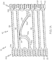
- the stent includes a plurality of openings 40 extending through the wall of the stent. As can be seen in FIGS. 1-4 , the openings 40 are defined in part by adjacent circumferential bands 20.
- the outer surface of the wall is the outer surface of the stent and the inner surface of the wall is the inner surface of the stent.
- an "inner surface" of the stent is a surface that defines the lumen of the stent and the "outer surface” of the stent is opposite the inner surface.
- the stent 10 has at least one anchor 28 that is positioned longitudinally adjacent to one or both ends of the stent.
- the distance of a first end of the anchor 28 from an end of the stent is 0 to 30% of the stent length. In some embodiments, the distance of the anchor 28 from an end of the stent is greater than 0% and no more than 30%.
- each anchor 28 engages two circumferential bands 20. This is shown for example in FIG. 3-4 . Thus, since each end of the anchor is engaged to a circumferential band 20, the anchor 28 has no free ends.
- an anchor 28 can engage two peaks of adjacent circumferential bands 20 (a peak to peak anchor, not shown); two valleys of adjacent circumferential bands (a valley to valley anchor, not shown); or a peak and a valley of adjacent circumferential bands (a peak to valley anchor, shown for example in FIGS. 1A-D ).
- the entire length of the anchor 28 is between two adjacent circumferential bands 20 and in other embodiments, only a portion of the length of the anchor 28 is between two adjacent circumferential bands.
- at least the protruding region 32 of the anchor 28 is positioned between two adjacent circumferential bands 20.
- an anchor 28 has a longitudinal length from about 0.15 inches (3.81 mm) to about 0.25 inches (6.35 mm). Since the anchor extends between two circumferential bands, the two circumferential bands are positioned about 0.225 inches (5.715 mm) to about 0.300 inches (7.620 mm) apart and linking members extending between the two circumferential bands have a longitudinal length of 0.225 inches (5.715 mm) to about 0.275 inches (6.985 mm).
- the stent 10 has one or more anchors 28 are positioned adjacent to only one end of the stent. In other embodiments, the stent has one or more anchors 28 positioned adjacent to both ends of the stent. In at least one embodiment, the anchors 28 are regularly spaced about the circumference of the stent 10. In some embodiments, the stent 10 has two, three, four, five, six or more anchors 28 adjacent to an end of the stent.
- the two circumferential bands 20a, 20b and at least one anchor 28 form an anchoring section 42 of the stent 10.
- the stent 10 has only one anchoring section 42.
- the single anchoring section 42 forms an end region of the stent.
- the stent 10 has two anchoring sections, each anchoring section forming an end region of the stent.
- the anchoring section 42 further includes at least one linking member 26 connecting the first and second circumferential bands 20a, 20b.
- the first and second circumferential bands 20a, 20b are out of phase and the linking members 26 are peak to valley linking members.
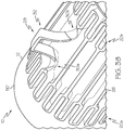
- a longitudinal distance between the first and second circumferential bands of the anchoring section is greater than a longitudinal distance between other longitudinally adjacent bands of the stent, as shown for example in FIG. 4 .
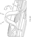
- an anchor 28 has an as-cut state and a set state.
- the anchors 28 in FIGS. 1A-D are in an as-cut state while FIGS. 2A-D show the anchors of FIGS. 1A-D in a set state.
- FIGS. 1A-D when the anchor 28 is in the as-cut state, the entire length of the anchor 28 forms a part of the wall of the stent 10 whereas when the anchor 28 is in the set state, a portion of the anchor 28 protrudes from the outer surface of the prosthesis, as can be seen in FIGS. 2A-D . If the stent has no cover, a portion of the anchor in the set state protrudes from the outer surface of the stent.
- protrude means to extend beyond, or to be positioned above, the outer surface of the prosthesis or the stent.
- the anchor 28 protrudes from the cover 50.
- the anchor 28 is configured to provide for tissue growth around the anchor 28.
- the configuration of the anchors 28 is nonlinear.
- each anchor 28 has at least one bend.
- the bend can be rounded or sharp.
- the anchor 28 can have any configuration so long as the anchor in the set state protrudes from the outer surface of the prosthesis.
- suitable configurations include a wave design, a square design, a rounded design, or a triangular design, as shown for example in FIGS. 1A-D and discussed below in greater detail.
- the anchors of a stent can have the same design/configuration or different designs/configurations.
- the anchor 28 in the set state has a first twist region 30a, a second twist region 30b, and a middle region 32 extending between the two twist regions.
- the first twist region 30a, the second twist region 30b, and the middle region 32 of the anchor 28 are positioned between two adjacent circumferential bands 20.
- peak to peak or valley to valley anchors will further include a straight region that extends from one twist region to the peak or the valley and that is between the two struts engaged to the peak or valley (not shown).
- a twist region 30 of the anchor 28 is a straight region 36 when the anchor 28 is in the as-cut state.
- a first surface of a twist region transitions from being a side surface to an outer surface of the anchor 28 and a second surface opposite the first surface transitions from being a side surface to an inner surface of the anchor 28. Formation of a twist region 30 is discussed in greater detail below.
- each twist region 30 is an end region of the anchor 28. In one embodiment, each twist region 30 is engaged to a circumferential band 20. As can be seen in FIGS. 2A-D , the two twist regions 30 of the anchor provides for a middle region 32 that protrudes from the outer surface of the prosthesis. Thus, the middle region 32 of the anchor 28 can be considered a protruding region or an anchor section.
- the inner surface of the protruding region 32 of the anchor 28 in the set state is positioned a distance away from the outer surface of the prosthesis and defines an open area of space for tissue growth therearound and therethrough.
- an “anchor gap” is the area of space between the anchor and the outer surface of the stent or prosthesis for tissue ingrowth after implantation.
- the anchor 28 in the set state has a height of about 0.50 in (1.27 mm) to about 0.10 in (2.54 mm) from the outer surface of the prosthesis or stent.
- middle region 32 of the anchor 28 protrudes a distance of about 0.50 in (1.27 mm) to about 0.10 in (2.54 mm) from the outer surface of the prosthesis or stent.
- an anchor 28 positioned a distance away from an end of the stent mitigates granulation tissue formation at or near the ends of the stent when the stent is implanted in a body lumen.
- the anchor(s) 28 limit migration of the stent.
- the anchor 28 is an anti-migration feature.
- a fully covered stent with at least one anchor implanted in a body lumen has a reduced stent migration because of tissue growth around the anchor and a reduced luminal occlusion because of the covering. Without being bound by theory, tissue ingrowth limits migration of the stent by anchoring the stent to the luminal wall.
- the amount of tissue ingrowth around the anchor affects migration.
- the longitudinal length of the protruding region 32 of the anchor 28 affects the amount of tissue ingrowth.
- an anchor with a sharp bend provides for greater tissue excitation and tissue ingrowth than an anchor with a rounded bend.
- a bend with an edge that is sharper to the touch than another edge that is less sharp will create greater tissue/cell excitation as it rubs against the airway wall thereby inducing inflammation and resulting in tissue ingrowth sooner compared to a bend that has a less sharp edge.
- minimizing migration of the stent minimizes formation of granulation tissue.
- a wave design for an anchor 28 is shown for example in FIG. 1A (as-cut state) and FIG. 3A (set state).
- the wave design includes a first region that is straight 36a, a first region that is curved 34a, a bend 38a, a second region that is curved 34b, and a second region that is straight 36b.
- the wave design further includes a bend connecting the second curved region 34b and the second straight region 36b.
- the bend 38a is sharp.
- the bend 38a is rounded. As used herein a sharp bend has a smaller radius of curvature than a rounded bend.
- FIG. 1A shows a bend 38a that is sharp.
- the first curved region 34a, the bend 38a, and the second curved region 34b form the protruding region 32 of the anchor 28 in the set state.
- the anchor gap is defined in part by the first curved region 34a, the bend 38a, and the second curved region 34b of the anchor 28 in the set state.
- the anchor gap is further defined by the outer surface of the cover 50.
- a wave design provides for aggressive tissue excitation when the stent is implanted in a body lumen.
- tissue ingrowth is correlated to tissue excitation.
- a wave design provides for an anchor that achieves anchoring of the stent in a body lumen quickly.
- a square design for an anchor 28 is shown for example in FIG. 1B (as-cut state) and FIG. 3B (set state).
- a square design includes a first region that is straight 36a, a first bend 38a, a second region that is either straight 34b or curved 36b, a second bend 38b, a third region that is straight 36c, a third bend 38c, a fourth region that is either straight 34d or curved 36d, a fourth bend 38d, and a fifth region that is straight 36e.
- the second and third bends 38b and 38c are rounded.
- the second and third bends 38a, 38b are sharp.
- FIG. 1B is showing rounded second and third bends 38b, 38c.
- the second region 34b/36b, the first bend 38a, the third region 36c, the second bend 38b, and the fourth region 34d/36d form the protruding region 32 of the anchor 28 in the set state.
- the anchor gap is defined in part by the second region 34b/36b, the first bend 38a, the third region 36c, the second bend 38b, and the fourth region 34d/36d of the anchor 28 in the set state.
- the anchor gap is further defined by the outer surface of the cover 50.
- the second and fourth regions are straight 36 when the anchor is in the as-cut state and curved 34 when the anchor is in the set state (compare FIGS. 1B and 3B ).
- the second and fourth regions are straight 36 when the anchor 28 is in the as-cut state and when the anchor 28 is in the set state (not shown).
- the third region 36c is substantially parallel to the outer surface of the prosthesis.
- a square design provides for a large volume of tissue ingrowth around the anchor when the stent is implanted in a body lumen. Without being bound by theory, the longitudinal length of the protruding region of the anchor affects the volume of tissue ingrowth.
- a rounded design for an anchor 28 is shown for example in FIG. 1C (as-cut state) and FIG. 3C (set state).
- the rounded design includes a first region that is straight 36a, a second region that is curved 34, and a third region that is straight 36b.
- the second region 34 includes two straight regions and a curved region connecting the two straight regions.
- the curved region 34 forms the protruding region 32 of the anchor 28 in the set state.
- the anchor gap is defined in part by the curved region 34 of the anchor 28 in the set state. In embodiments with a cover 50 discussed below, the anchor gap is further defined by the outer surface of the cover 50.
- a rounded design provides for very little tissue excitation when the stent is implanted in a body lumen.
- a stent with anchors having a rounded design is implanted at a location where the tissue is inflamed prior to implantation of the stent.
- a triangular design for an anchor 28 is shown for example in FIG. 1D (as-cut state) and FIG. 3D (set state).
- the triangular design includes a first region that is straight 36a, a first bend 38a, a second region that is straight 36b, a second bend 38b, a third region that is straight 36c, a third bend 38c, and a fourth region that is straight 36d.
- the second bend 38b is rounded.
- the second bend 38b is sharp.
- the second straight region 36b, the second bend 38b, and the third straight region 36c form the protruding region 32 of the anchor 28 in the set state.
- the anchor gap is defined in part by the second straight region 36b, the second bend 38b, and the third straight region 36c of the anchor 28 in the set state. In embodiments with a cover 50 discussed below, the anchor gap is further defined by the outer surface of the cover 50.
- a triangular design causes mild tissue excitation when the stent is implanted in a body lumen. In other embodiments, a triangular design provides for relatively quick anchoring of a stent after implantation in a body lumen.
- the stent 10 as has several states, an "as cut state,” followed by a “heat set state,” followed by a “crimped state,” followed by a “deployed state.”
- a stent is in an "as cut state” after laser cutting and prior to heat setting; a stent is in the "heat set state” after the as cut state and after being heat treated; a stent is in a “crimped state” when positioned on a delivery device; and a stent is in the "deployed state” when it is deployed in a body lumen.
- FIG. 4 shows the stent 10 deployed in a vessel 60. As shown in FIG. 4 , the anchors 28 are embedded in the wall of the vessel 60.
- the stent 10 has a cover 50, as shown for example in FIGS. 3A-D .
- the stent 10 has a cover 50 when the stent 10 is in the crimped state and when the stent 10 is in the deployed state.
- a "cover” 50 extends over the openings 40 defined by the stent wall thereby occluding the openings and preventing tissue growth through the openings and into the lumen of the prosthesis.
- the prosthesis 10 is a fully covered stent.
- a "fully covered stent" has a cover 50 that extends at least from the first end to the second end of the stent.
- the cover 50 of a fully covered stent has a length equal to or greater than the length of the stent 10.
- a "covered stent” has a cover 50 with a longitudinal length less than the longitudinal length of the stent.
- the cover 50 can be positioned over a) the outer surface of the wall of the stent; b) the inner surface of the wall of the stent; or c) both the inner surface and outer surface of the wall of the stent.
- the cover 50 has a thickness that is a) less than the thickness of the wall of the stent; b) equal to the thickness of the wall of the stent; or c) greater than the thickness of the wall of the stent.
- Reference hereinafter to the outer surface 12 of the prosthesis includes a) embodiments where the outer surface 12 of the prosthesis is formed by the stent and the cover 50, and b) embodiments where the outer surface 12 of the prosthesis is formed only by the cover 50.
- the stent, the delivery system or other portion of the assembly may include one or more areas, bands, coatings, members, etc. that is (are) detectable by imaging modalities such as X-Ray, MRI, ultrasound, etc.
- imaging modalities such as X-Ray, MRI, ultrasound, etc.
- at least a portion of the stent and/or adjacent assembly is at least partially radiopaque.
- the at least a portion of the stent 10 is configured to include one or more mechanisms for the delivery of a therapeutic agent.
- the agent will be in the form of a coating or other layer (or layers) of material placed on a surface region of the stent, which is adapted to be released at the site of the stent's implantation or areas adjacent thereto.
- a layer or coating of therapeutic agent as used herein is not a cover 50 as used herein because the therapeutic agent does not extend over and occlude the openings defined by the wall of the stent.
- the protruding region 32 of the anchor 28 has a therapeutic agent deposited thereon.
- a "therapeutic agent” is a drug or other pharmaceutical product used to treating, preventing, or alleviating the symptoms of disease.
- Therapeutic agents include non-genetic agents, genetic agents, cellular material, etc.
- suitable non-genetic therapeutic agents include but are not limited to: anti-thrombogenic agents such as heparin, heparin derivatives, vascular cell growth promoters, growth factor inhibitors, Paclitaxel, etc.
- an agent includes a genetic therapeutic agent, such a genetic agent may include but is not limited to: DNA, RNA and their respective derivatives and/or components; hedgehog proteins, etc.
- the cellular material may include but is not limited to: cells of human origin and/or non-human origin as well as their respective components and/or derivatives thereof.
- the polymer agent may be a polystyrene-polyisobutylene-polystyrene triblock copolymer (SIBS), polyethylene oxide, silicone rubber and/or any other suitable substrate.
- the stent 10 in each of the several states, comprises an outer surface 12, an inner surface 14, a longitudinal length extending from a first end to a second end, a plurality of circumferential bands 20, a plurality of linking members 26, and at least one anchor 28.
- the at least one anchor 28 is in the as-cut state when the stent is in the as-cut state.
- the at least one anchor 28 is in the set state when the stent is in the crimped state and when the stent is in the deployed state.
- the delivery device is configured to carry a stent with at least one anchor 28 in the set state.
- a method of forming a stent includes forming the as-cut state of the stent 10; transforming the at least one anchor 28 from the as-cut state to the set state; and optionally applying a cover 50 to the stent.
- a therapeutic agent is selectively applied to the protruding portions of the anchors 28.
- Step of Forming the as-cut state of the stent
- the as-cut state of the stent 10 is formed by laser cutting or etching a pattern in a tube of stent material. In other embodiments, the as-cut state of the stent 10 is formed by laser cutting or etching a pattern in a flat sheet of stent material, and forming a tube by rolling and joining the long edge of the sheet.
- the pattern includes a plurality of circumferential bands 20, a plurality of linking members 26, and at least one anchor 28, as discussed above.
- the pattern includes an anchoring section 42.
- the anchor 28 in the as-cut state has a thickness of about 0.01 inches (0.25 mm).
- the stent 10 may be made from any suitable biocompatible materials including one or more polymers, one or more metals or combinations of polymer(s) and metal(s).
- suitable materials include biodegradable materials that are also biocompatible. By biodegradable is meant that a material will undergo breakdown or decomposition into harmless compounds as part of a normal biological process.
- Suitable biodegradable materials include polylactic acid, polyglycolic acid (PGA), collagen or other connective proteins or natural materials, polycaprolactone, hylauric acid, adhesive proteins, co-polymers of these materials as well as composites and combinations thereof and combinations of other biodegradable polymers.
- Other polymers that may be used include polyester and polycarbonate copolymers.
- suitable metals include, but are not limited to, stainless steel, titanium, tantalum, platinum, tungsten, gold and alloys of any of the above-mentioned metals.
- suitable alloys include platinum-iridium alloys, cobalt-chromium alloys including Elgiloy and Phynox, MP35N alloy and nickel-titanium alloys, for example, Nitinol.
- the inventive stents may be made of shape memory materials such as superelastic Nitinol or spring steel, or may be made of materials which are plastically deformable.
- shape memory materials such as superelastic Nitinol or spring steel, or may be made of materials which are plastically deformable.
- the stent may be provided with a memorized shape and then deformed to a reduced diameter shape for delivery to a body lumen.
- the stent may restore itself to its memorized shape in a body lumen upon being heated to a transition temperature and having any restraints removed therefrom.
- the anchor 28 in the as-cut state is transformed to an anchor in a set state.
- transforming the anchor 28 from the as-cut state to the set state comprises twisting or turning the anchor 28 outward so that a portion of the anchor protrudes from the outer surface of the prosthesis or stent.
- a surface of a twist region 30 of the anchor 28 transitions from being a side surface to being an outer surface of the anchor 28. This can be seen for example in FIGS. 2A-D . As can be seen, the side surface is adjacent to an end of the anchor and the outer surface is adjacent to the middle region of the anchor.
- the width of the anchor 28 in the set state is equal to the thickness of the anchor 28 in the as-cut state.
- transforming the anchor 28 from the as-cut state to the set state comprises forming one or more twist regions 30.
- one or more twist regions are formed by twisting or turning the anchor 28 outward so that a portion of the anchor protrudes from the outer surface of the prosthesis or stent.
- the anchor 28 is heat set after being twisted to maintain the set state of the anchor.
- the wall of the stent 10 has a thickness.
- the anchor 28 when the anchor 28 is in the cut state, the anchor has a thickness equal to the thickness of the wall, and when the anchor is in the set state, the anchor has a width equal to the thickness of the wall of the stent. This can be seen for example in FIGS. 1-2 .
- a cover 50 is applied to the stent 10. In some embodiments, a cover 50 is applied to the stent 10 after the one or more anchors 28 have been heat set to the set state. In some embodiments, the cover 50 has a length at least equal to the length of the stent 10. In other embodiments, the cover 50 has a length greater than the length of the stent 10.
- the stent is a fully covered stent.
- a cover 50 can be applied in any suitable manner that covers and obstructs the openings 40 in the wall of the stent 10. In some embodiments, the cover 50 is applied by dip coating the stent 10. In other embodiments, the cover 50 is applied by spray-coating coating material onto the stent 10.
- cover material applied to is removed to form the anchor gap.
- cover material applied to the surface of the protruding region 32 of the anchor 28 are also removed so that the protruding region 32 is exposed from, or bare of, the cover 50. In other words, the protruding region 32 has no cover material thereon. Any method to remove the cover material to form the anchor gap or to remove the cover material on the surfaces of the anchor 28 can be used so long as the cover 50 is not punctured. As discussed above, the cover 50 prevents the lumen of the prosthesis from being occluded by tissue ingrowth.
- a laser is used to form the anchor gap and to remove cover material on the protruding region 32 of the anchor 28.
- a suitable laser is a YAG laser.
- the stent is held in place while the cover material is being removed.
- the stent is on a mandrel.
- the anchor gap is filled with an epoxy during the coating process and after the coating has been applied, the epoxy is dissolved to form the anchor gap.
- coating in the anchor gap is punched out with a dye or other device with a shape that matches the geometry of the anchor gap. In one laser is used to remove cover material from the anchor so that the protruding region 32 of the anchor 28 is bare.
- Suitable materials for the cover 50 include any other type of material that prevents tumor or tissue ingrowth through at least some of the openings 40.
- Non-limiting examples include silicone elastomers, polyurethane, polystyrene-polyisobutylene-polystyrene triblock copolymer (SIBS), ePTFE, and combinations thereof.
- any dependent claim which follows should be taken as alternatively written in a multiple dependent form from all prior claims which possess all antecedents referenced in such dependent claim if such multiple dependent format is an accepted format within the jurisdiction (e.g. each claim depending directly from claim 1 should be alternatively taken as depending from all previous claims).
- each claim depending directly from claim 1 should be alternatively taken as depending from all previous claims.
- the following dependent claims should each be also taken as alternatively written in each singly dependent claim format which creates a dependency from a prior antecedent-possessing claim other than the specific claim listed in such dependent claim below.
Landscapes
- Health & Medical Sciences (AREA)
- Engineering & Computer Science (AREA)
- Biomedical Technology (AREA)
- Heart & Thoracic Surgery (AREA)
- Life Sciences & Earth Sciences (AREA)
- Cardiology (AREA)
- Oral & Maxillofacial Surgery (AREA)
- Transplantation (AREA)
- Veterinary Medicine (AREA)
- Vascular Medicine (AREA)
- Public Health (AREA)
- Animal Behavior & Ethology (AREA)
- General Health & Medical Sciences (AREA)
- Optics & Photonics (AREA)
- Physics & Mathematics (AREA)
- Prostheses (AREA)
- Media Introduction/Drainage Providing Device (AREA)
Applications Claiming Priority (2)
| Application Number | Priority Date | Filing Date | Title |
|---|---|---|---|
| US201361779414P | 2013-03-13 | 2013-03-13 | |
| PCT/US2014/022639 WO2014159237A1 (en) | 2013-03-13 | 2014-03-10 | Anti-migration tissue anchoring system for a fully covered stent |
Publications (2)
| Publication Number | Publication Date |
|---|---|
| EP2967930A1 EP2967930A1 (en) | 2016-01-20 |
| EP2967930B1 true EP2967930B1 (en) | 2018-11-28 |
Family
ID=50346197
Family Applications (1)
| Application Number | Title | Priority Date | Filing Date |
|---|---|---|---|
| EP14712175.0A Active EP2967930B1 (en) | 2013-03-13 | 2014-03-10 | Anti-migration tissue anchoring system for a fully covered stent |
Country Status (7)
| Country | Link |
|---|---|
| US (1) | US20140277562A1 (zh) |
| EP (1) | EP2967930B1 (zh) |
| JP (2) | JP6471143B2 (zh) |
| CN (1) | CN105208977B (zh) |
| AU (2) | AU2014241068B2 (zh) |
| CA (1) | CA2905736C (zh) |
| WO (1) | WO2014159237A1 (zh) |
Cited By (1)
| Publication number | Priority date | Publication date | Assignee | Title |
|---|---|---|---|---|
| US11992220B2 (en) | 2022-03-30 | 2024-05-28 | Boston Scientific Scimed, Inc. | Occlusive medical device with fixation members |
Families Citing this family (14)
| Publication number | Priority date | Publication date | Assignee | Title |
|---|---|---|---|---|
| CA3010828A1 (en) | 2008-01-17 | 2009-07-23 | Boston Scientific Scimed, Inc. | Stent with anti-migration feature |
| EP3043754B1 (en) | 2013-09-12 | 2020-02-12 | Boston Scientific Scimed, Inc. | Stent with anti-migration connectors |
| WO2015114463A2 (en) * | 2014-02-02 | 2015-08-06 | Gil Hefer | Apparatus and methods for recannalization, valve repair and replacement |
| WO2016054536A1 (en) * | 2014-10-02 | 2016-04-07 | Boston Scientific Scimed, Inc. | Controlled ingrowth feature for antimigration |
| CN107106310B (zh) * | 2014-10-22 | 2019-03-22 | 波士顿科学国际有限公司 | 具有柔性铰链的支架 |
| US20160128852A1 (en) | 2014-11-06 | 2016-05-12 | Boston Scientific Scimed, Inc. | Tracheal stent |
| US9956095B2 (en) * | 2015-08-05 | 2018-05-01 | Sanford Health | Self-expanding bridging stent with anchoring projections and methods for use |
| WO2018059219A1 (zh) * | 2016-09-30 | 2018-04-05 | 苏州茵络医疗器械有限公司 | 用于植入血管的支架 |
| CA3158845A1 (en) * | 2017-09-12 | 2019-03-21 | W. L. Gore & Associates, Inc. | Substrate with rotatable struts for medical device |
| EP3473214A1 (de) * | 2017-10-18 | 2019-04-24 | Biotronik AG | Ballonkathether-stent-vorrichtung |
| US11331103B2 (en) * | 2018-03-29 | 2022-05-17 | Boston Scientific Scimed, Inc. | Occlusive medical device with fixation members |
| JP2023510553A (ja) | 2020-01-13 | 2023-03-14 | ボストン サイエンティフィック サイムド,インコーポレイテッド | 移動防止ステント |
| KR20220137702A (ko) | 2020-02-03 | 2022-10-12 | 보스톤 싸이엔티픽 싸이메드 인코포레이티드 | 스텐트, 맨드렐 및 이동-방지 특징부를 가진 스텐트를 형성하기 위한 방법 |
| WO2021195665A1 (en) * | 2020-03-24 | 2021-09-30 | The Foundry, Llc | Expandable devices and associated systems and methods |
Citations (1)
| Publication number | Priority date | Publication date | Assignee | Title |
|---|---|---|---|---|
| US20040117004A1 (en) * | 2002-05-16 | 2004-06-17 | Osborne Thomas A. | Stent and method of forming a stent with integral barbs |
Family Cites Families (23)
| Publication number | Priority date | Publication date | Assignee | Title |
|---|---|---|---|---|
| US5591197A (en) * | 1995-03-14 | 1997-01-07 | Advanced Cardiovascular Systems, Inc. | Expandable stent forming projecting barbs and method for deploying |
| CA2171896C (en) * | 1995-03-17 | 2007-05-15 | Scott C. Anderson | Multi-anchor stent |
| NZ331269A (en) * | 1996-04-10 | 2000-01-28 | Advanced Cardiovascular System | Expandable stent, its structural strength varying along its length |
| US6443972B1 (en) * | 1997-11-19 | 2002-09-03 | Cordis Europa N.V. | Vascular filter |
| WO1999056663A2 (en) * | 1998-05-05 | 1999-11-11 | Scimed Life Systems, Inc. | Stent with smooth ends |
| JP4739533B2 (ja) * | 1999-05-20 | 2011-08-03 | ボストン サイエンティフィック リミテッド | 可撓性の増大したステント−移植片 |
| US7060089B2 (en) * | 2002-01-23 | 2006-06-13 | Boston Scientific Scimed, Inc. | Multi-layer stent |
| US20030220683A1 (en) * | 2002-05-22 | 2003-11-27 | Zarouhi Minasian | Endoluminal device having barb assembly and method of using same |
| WO2004006983A2 (en) * | 2002-07-11 | 2004-01-22 | University Of Virginia Patent Foundation | Expandable body having deployable microstructures and related methods |
| US20050096731A1 (en) * | 2002-07-11 | 2005-05-05 | Kareen Looi | Cell seeded expandable body |
| US20040054398A1 (en) * | 2002-09-13 | 2004-03-18 | Cully Edward H. | Stent device with multiple helix construction |
| US7258697B1 (en) * | 2003-12-22 | 2007-08-21 | Advanced Cardiovascular Systems, Inc. | Stent with anchors to prevent vulnerable plaque rupture during deployment |
| US7854756B2 (en) * | 2004-01-22 | 2010-12-21 | Boston Scientific Scimed, Inc. | Medical devices |
| CA2585422C (en) * | 2004-10-26 | 2010-08-17 | Cordis Corporation | Stent having phased hoop sections |
| WO2006074476A2 (en) * | 2005-01-10 | 2006-07-13 | Trireme Medical, Inc. | Stent with self-deployable portion |
| US9101500B2 (en) * | 2005-01-10 | 2015-08-11 | Trireme Medical, Inc. | Stent with self-deployable portion having wings of different lengths |
| US8608789B2 (en) * | 2005-05-24 | 2013-12-17 | Trireme Medical, Inc. | Delivery system for bifurcation stents |
| US20080103584A1 (en) * | 2006-10-25 | 2008-05-01 | Biosensors International Group | Temporal Intraluminal Stent, Methods of Making and Using |
| CA3010828A1 (en) * | 2008-01-17 | 2009-07-23 | Boston Scientific Scimed, Inc. | Stent with anti-migration feature |
| CN102655825B (zh) * | 2009-09-16 | 2015-07-08 | 本特利因诺美有限责任公司 | 带有延展元件的支架 |
| WO2012147675A1 (ja) * | 2011-04-27 | 2012-11-01 | 株式会社パイオラックスメディカルデバイス | ステント |
| US20120283811A1 (en) * | 2011-05-02 | 2012-11-08 | Cook Medical Technologies Llc | Biodegradable, bioabsorbable stent anchors |
| US10285798B2 (en) * | 2011-06-03 | 2019-05-14 | Merit Medical Systems, Inc. | Esophageal stent |
-
2014
- 2014-03-10 US US14/202,896 patent/US20140277562A1/en not_active Abandoned
- 2014-03-10 AU AU2014241068A patent/AU2014241068B2/en not_active Ceased
- 2014-03-10 JP JP2016501024A patent/JP6471143B2/ja active Active
- 2014-03-10 WO PCT/US2014/022639 patent/WO2014159237A1/en active Application Filing
- 2014-03-10 EP EP14712175.0A patent/EP2967930B1/en active Active
- 2014-03-10 CN CN201480028008.7A patent/CN105208977B/zh active Active
- 2014-03-10 CA CA2905736A patent/CA2905736C/en not_active Expired - Fee Related
-
2017
- 2017-06-20 AU AU2017204177A patent/AU2017204177B2/en not_active Ceased
- 2017-06-29 JP JP2017127721A patent/JP6396541B2/ja active Active
Patent Citations (1)
| Publication number | Priority date | Publication date | Assignee | Title |
|---|---|---|---|---|
| US20040117004A1 (en) * | 2002-05-16 | 2004-06-17 | Osborne Thomas A. | Stent and method of forming a stent with integral barbs |
Cited By (1)
| Publication number | Priority date | Publication date | Assignee | Title |
|---|---|---|---|---|
| US11992220B2 (en) | 2022-03-30 | 2024-05-28 | Boston Scientific Scimed, Inc. | Occlusive medical device with fixation members |
Also Published As
| Publication number | Publication date |
|---|---|
| JP2016511104A (ja) | 2016-04-14 |
| CN105208977A (zh) | 2015-12-30 |
| AU2017204177B2 (en) | 2019-01-31 |
| CN105208977B (zh) | 2020-06-09 |
| AU2014241068A1 (en) | 2015-10-15 |
| EP2967930A1 (en) | 2016-01-20 |
| CA2905736A1 (en) | 2014-10-02 |
| JP2017192780A (ja) | 2017-10-26 |
| WO2014159237A1 (en) | 2014-10-02 |
| CA2905736C (en) | 2018-05-01 |
| AU2017204177A1 (en) | 2017-07-13 |
| US20140277562A1 (en) | 2014-09-18 |
| JP6471143B2 (ja) | 2019-02-13 |
| JP6396541B2 (ja) | 2018-09-26 |
| AU2014241068B2 (en) | 2017-04-20 |
Similar Documents
| Publication | Publication Date | Title |
|---|---|---|
| EP2967930B1 (en) | Anti-migration tissue anchoring system for a fully covered stent | |
| EP1954223B1 (en) | Stent configurations | |
| EP2394611B1 (en) | Hybrid stent | |
| EP2043567B1 (en) | Stent design with variable expansion columns along circumference | |
| US7381217B2 (en) | Serpentine stent pattern | |
| EP1786358B1 (en) | Flap-cover aneurysm stent | |
| EP2658485B1 (en) | Stent | |
| US8512395B2 (en) | Stent with horseshoe shaped bridges | |
| US20060271161A1 (en) | Selective treatment of stent side branch petals | |
| US20080071346A1 (en) | Multilayer Sheet Stent | |
| WO2007102974A1 (en) | Bifurcation stent with uniform side branch projection | |
| US20100010618A1 (en) | Overlapping Stent |
Legal Events
| Date | Code | Title | Description |
|---|---|---|---|
| PUAI | Public reference made under article 153(3) epc to a published international application that has entered the european phase |
Free format text: ORIGINAL CODE: 0009012 |
|
| 17P | Request for examination filed |
Effective date: 20151007 |
|
| AK | Designated contracting states |
Kind code of ref document: A1 Designated state(s): AL AT BE BG CH CY CZ DE DK EE ES FI FR GB GR HR HU IE IS IT LI LT LU LV MC MK MT NL NO PL PT RO RS SE SI SK SM TR |
|
| AX | Request for extension of the european patent |
Extension state: BA ME |
|
| DAX | Request for extension of the european patent (deleted) | ||
| RIN1 | Information on inventor provided before grant (corrected) |
Inventor name: ROSS, DANIEL Inventor name: DORAN, BURNS P. Inventor name: SEDDON, DANE T. Inventor name: WOOD, MARK D. Inventor name: FLEURY, SEAN P. |
|
| 17Q | First examination report despatched |
Effective date: 20161011 |
|
| STAA | Information on the status of an ep patent application or granted ep patent |
Free format text: STATUS: EXAMINATION IS IN PROGRESS |
|
| GRAP | Despatch of communication of intention to grant a patent |
Free format text: ORIGINAL CODE: EPIDOSNIGR1 |
|
| STAA | Information on the status of an ep patent application or granted ep patent |
Free format text: STATUS: GRANT OF PATENT IS INTENDED |
|
| INTG | Intention to grant announced |
Effective date: 20180110 |
|
| GRAJ | Information related to disapproval of communication of intention to grant by the applicant or resumption of examination proceedings by the epo deleted |
Free format text: ORIGINAL CODE: EPIDOSDIGR1 |
|
| STAA | Information on the status of an ep patent application or granted ep patent |
Free format text: STATUS: EXAMINATION IS IN PROGRESS |
|
| GRAS | Grant fee paid |
Free format text: ORIGINAL CODE: EPIDOSNIGR3 |
|
| STAA | Information on the status of an ep patent application or granted ep patent |
Free format text: STATUS: GRANT OF PATENT IS INTENDED |
|
| GRAS | Grant fee paid |
Free format text: ORIGINAL CODE: EPIDOSNIGR3 |
|
| GRAS | Grant fee paid |
Free format text: ORIGINAL CODE: EPIDOSNIGR3 |
|
| INTC | Intention to grant announced (deleted) | ||
| GRAP | Despatch of communication of intention to grant a patent |
Free format text: ORIGINAL CODE: EPIDOSNIGR1 |
|
| GRAJ | Information related to disapproval of communication of intention to grant by the applicant or resumption of examination proceedings by the epo deleted |
Free format text: ORIGINAL CODE: EPIDOSDIGR1 |
|
| GRAS | Grant fee paid |
Free format text: ORIGINAL CODE: EPIDOSNIGR3 |
|
| GRAP | Despatch of communication of intention to grant a patent |
Free format text: ORIGINAL CODE: EPIDOSNIGR1 |
|
| INTG | Intention to grant announced |
Effective date: 20180625 |
|
| INTG | Intention to grant announced |
Effective date: 20180706 |
|
| GRAJ | Information related to disapproval of communication of intention to grant by the applicant or resumption of examination proceedings by the epo deleted |
Free format text: ORIGINAL CODE: EPIDOSDIGR1 |
|
| STAA | Information on the status of an ep patent application or granted ep patent |
Free format text: STATUS: EXAMINATION IS IN PROGRESS |
|
| GRAS | Grant fee paid |
Free format text: ORIGINAL CODE: EPIDOSNIGR3 |
|
| STAA | Information on the status of an ep patent application or granted ep patent |
Free format text: STATUS: GRANT OF PATENT IS INTENDED |
|
| GRAP | Despatch of communication of intention to grant a patent |
Free format text: ORIGINAL CODE: EPIDOSNIGR1 |
|
| INTG | Intention to grant announced |
Effective date: 20180831 |
|
| GRAA | (expected) grant |
Free format text: ORIGINAL CODE: 0009210 |
|
| STAA | Information on the status of an ep patent application or granted ep patent |
Free format text: STATUS: THE PATENT HAS BEEN GRANTED |
|
| AK | Designated contracting states |
Kind code of ref document: B1 Designated state(s): AL AT BE BG CH CY CZ DE DK EE ES FI FR GB GR HR HU IE IS IT LI LT LU LV MC MK MT NL NO PL PT RO RS SE SI SK SM TR |
|
| REG | Reference to a national code |
Ref country code: CH Ref legal event code: EP |
|
| REG | Reference to a national code |
Ref country code: AT Ref legal event code: REF Ref document number: 1069356 Country of ref document: AT Kind code of ref document: T Effective date: 20181215 |
|
| REG | Reference to a national code |
Ref country code: DE Ref legal event code: R096 Ref document number: 602014036883 Country of ref document: DE |
|
| REG | Reference to a national code |
Ref country code: IE Ref legal event code: FG4D |
|
| REG | Reference to a national code |
Ref country code: NL Ref legal event code: MP Effective date: 20181128 |
|
| REG | Reference to a national code |
Ref country code: LT Ref legal event code: MG4D |
|
| REG | Reference to a national code |
Ref country code: AT Ref legal event code: MK05 Ref document number: 1069356 Country of ref document: AT Kind code of ref document: T Effective date: 20181128 |
|
| PG25 | Lapsed in a contracting state [announced via postgrant information from national office to epo] |
Ref country code: ES Free format text: LAPSE BECAUSE OF FAILURE TO SUBMIT A TRANSLATION OF THE DESCRIPTION OR TO PAY THE FEE WITHIN THE PRESCRIBED TIME-LIMIT Effective date: 20181128 Ref country code: LV Free format text: LAPSE BECAUSE OF FAILURE TO SUBMIT A TRANSLATION OF THE DESCRIPTION OR TO PAY THE FEE WITHIN THE PRESCRIBED TIME-LIMIT Effective date: 20181128 Ref country code: HR Free format text: LAPSE BECAUSE OF FAILURE TO SUBMIT A TRANSLATION OF THE DESCRIPTION OR TO PAY THE FEE WITHIN THE PRESCRIBED TIME-LIMIT Effective date: 20181128 Ref country code: LT Free format text: LAPSE BECAUSE OF FAILURE TO SUBMIT A TRANSLATION OF THE DESCRIPTION OR TO PAY THE FEE WITHIN THE PRESCRIBED TIME-LIMIT Effective date: 20181128 Ref country code: BG Free format text: LAPSE BECAUSE OF FAILURE TO SUBMIT A TRANSLATION OF THE DESCRIPTION OR TO PAY THE FEE WITHIN THE PRESCRIBED TIME-LIMIT Effective date: 20190228 Ref country code: IS Free format text: LAPSE BECAUSE OF FAILURE TO SUBMIT A TRANSLATION OF THE DESCRIPTION OR TO PAY THE FEE WITHIN THE PRESCRIBED TIME-LIMIT Effective date: 20190328 Ref country code: FI Free format text: LAPSE BECAUSE OF FAILURE TO SUBMIT A TRANSLATION OF THE DESCRIPTION OR TO PAY THE FEE WITHIN THE PRESCRIBED TIME-LIMIT Effective date: 20181128 Ref country code: NO Free format text: LAPSE BECAUSE OF FAILURE TO SUBMIT A TRANSLATION OF THE DESCRIPTION OR TO PAY THE FEE WITHIN THE PRESCRIBED TIME-LIMIT Effective date: 20190228 Ref country code: AT Free format text: LAPSE BECAUSE OF FAILURE TO SUBMIT A TRANSLATION OF THE DESCRIPTION OR TO PAY THE FEE WITHIN THE PRESCRIBED TIME-LIMIT Effective date: 20181128 |
|
| PG25 | Lapsed in a contracting state [announced via postgrant information from national office to epo] |
Ref country code: RS Free format text: LAPSE BECAUSE OF FAILURE TO SUBMIT A TRANSLATION OF THE DESCRIPTION OR TO PAY THE FEE WITHIN THE PRESCRIBED TIME-LIMIT Effective date: 20181128 Ref country code: SE Free format text: LAPSE BECAUSE OF FAILURE TO SUBMIT A TRANSLATION OF THE DESCRIPTION OR TO PAY THE FEE WITHIN THE PRESCRIBED TIME-LIMIT Effective date: 20181128 Ref country code: GR Free format text: LAPSE BECAUSE OF FAILURE TO SUBMIT A TRANSLATION OF THE DESCRIPTION OR TO PAY THE FEE WITHIN THE PRESCRIBED TIME-LIMIT Effective date: 20190301 Ref country code: PT Free format text: LAPSE BECAUSE OF FAILURE TO SUBMIT A TRANSLATION OF THE DESCRIPTION OR TO PAY THE FEE WITHIN THE PRESCRIBED TIME-LIMIT Effective date: 20190328 Ref country code: AL Free format text: LAPSE BECAUSE OF FAILURE TO SUBMIT A TRANSLATION OF THE DESCRIPTION OR TO PAY THE FEE WITHIN THE PRESCRIBED TIME-LIMIT Effective date: 20181128 |
|
| PG25 | Lapsed in a contracting state [announced via postgrant information from national office to epo] |
Ref country code: NL Free format text: LAPSE BECAUSE OF FAILURE TO SUBMIT A TRANSLATION OF THE DESCRIPTION OR TO PAY THE FEE WITHIN THE PRESCRIBED TIME-LIMIT Effective date: 20181128 |
|
| PG25 | Lapsed in a contracting state [announced via postgrant information from national office to epo] |
Ref country code: DK Free format text: LAPSE BECAUSE OF FAILURE TO SUBMIT A TRANSLATION OF THE DESCRIPTION OR TO PAY THE FEE WITHIN THE PRESCRIBED TIME-LIMIT Effective date: 20181128 Ref country code: IT Free format text: LAPSE BECAUSE OF FAILURE TO SUBMIT A TRANSLATION OF THE DESCRIPTION OR TO PAY THE FEE WITHIN THE PRESCRIBED TIME-LIMIT Effective date: 20181128 Ref country code: CZ Free format text: LAPSE BECAUSE OF FAILURE TO SUBMIT A TRANSLATION OF THE DESCRIPTION OR TO PAY THE FEE WITHIN THE PRESCRIBED TIME-LIMIT Effective date: 20181128 Ref country code: PL Free format text: LAPSE BECAUSE OF FAILURE TO SUBMIT A TRANSLATION OF THE DESCRIPTION OR TO PAY THE FEE WITHIN THE PRESCRIBED TIME-LIMIT Effective date: 20181128 |
|
| REG | Reference to a national code |
Ref country code: DE Ref legal event code: R097 Ref document number: 602014036883 Country of ref document: DE |
|
| PG25 | Lapsed in a contracting state [announced via postgrant information from national office to epo] |
Ref country code: RO Free format text: LAPSE BECAUSE OF FAILURE TO SUBMIT A TRANSLATION OF THE DESCRIPTION OR TO PAY THE FEE WITHIN THE PRESCRIBED TIME-LIMIT Effective date: 20181128 Ref country code: SK Free format text: LAPSE BECAUSE OF FAILURE TO SUBMIT A TRANSLATION OF THE DESCRIPTION OR TO PAY THE FEE WITHIN THE PRESCRIBED TIME-LIMIT Effective date: 20181128 Ref country code: SM Free format text: LAPSE BECAUSE OF FAILURE TO SUBMIT A TRANSLATION OF THE DESCRIPTION OR TO PAY THE FEE WITHIN THE PRESCRIBED TIME-LIMIT Effective date: 20181128 Ref country code: EE Free format text: LAPSE BECAUSE OF FAILURE TO SUBMIT A TRANSLATION OF THE DESCRIPTION OR TO PAY THE FEE WITHIN THE PRESCRIBED TIME-LIMIT Effective date: 20181128 |
|
| PLBE | No opposition filed within time limit |
Free format text: ORIGINAL CODE: 0009261 |
|
| STAA | Information on the status of an ep patent application or granted ep patent |
Free format text: STATUS: NO OPPOSITION FILED WITHIN TIME LIMIT |
|
| PG25 | Lapsed in a contracting state [announced via postgrant information from national office to epo] |
Ref country code: SI Free format text: LAPSE BECAUSE OF FAILURE TO SUBMIT A TRANSLATION OF THE DESCRIPTION OR TO PAY THE FEE WITHIN THE PRESCRIBED TIME-LIMIT Effective date: 20181128 Ref country code: MC Free format text: LAPSE BECAUSE OF FAILURE TO SUBMIT A TRANSLATION OF THE DESCRIPTION OR TO PAY THE FEE WITHIN THE PRESCRIBED TIME-LIMIT Effective date: 20181128 |
|
| REG | Reference to a national code |
Ref country code: CH Ref legal event code: PL |
|
| 26N | No opposition filed |
Effective date: 20190829 |
|
| PG25 | Lapsed in a contracting state [announced via postgrant information from national office to epo] |
Ref country code: LU Free format text: LAPSE BECAUSE OF NON-PAYMENT OF DUE FEES Effective date: 20190310 |
|
| REG | Reference to a national code |
Ref country code: BE Ref legal event code: MM Effective date: 20190331 |
|
| PG25 | Lapsed in a contracting state [announced via postgrant information from national office to epo] |
Ref country code: LI Free format text: LAPSE BECAUSE OF NON-PAYMENT OF DUE FEES Effective date: 20190331 Ref country code: CH Free format text: LAPSE BECAUSE OF NON-PAYMENT OF DUE FEES Effective date: 20190331 |
|
| PG25 | Lapsed in a contracting state [announced via postgrant information from national office to epo] |
Ref country code: BE Free format text: LAPSE BECAUSE OF NON-PAYMENT OF DUE FEES Effective date: 20190331 |
|
| PG25 | Lapsed in a contracting state [announced via postgrant information from national office to epo] |
Ref country code: TR Free format text: LAPSE BECAUSE OF FAILURE TO SUBMIT A TRANSLATION OF THE DESCRIPTION OR TO PAY THE FEE WITHIN THE PRESCRIBED TIME-LIMIT Effective date: 20181128 |
|
| PG25 | Lapsed in a contracting state [announced via postgrant information from national office to epo] |
Ref country code: MT Free format text: LAPSE BECAUSE OF NON-PAYMENT OF DUE FEES Effective date: 20190310 |
|
| PGFP | Annual fee paid to national office [announced via postgrant information from national office to epo] |
Ref country code: FR Payment date: 20200214 Year of fee payment: 7 |
|
| PG25 | Lapsed in a contracting state [announced via postgrant information from national office to epo] |
Ref country code: CY Free format text: LAPSE BECAUSE OF FAILURE TO SUBMIT A TRANSLATION OF THE DESCRIPTION OR TO PAY THE FEE WITHIN THE PRESCRIBED TIME-LIMIT Effective date: 20181128 |
|
| PG25 | Lapsed in a contracting state [announced via postgrant information from national office to epo] |
Ref country code: HU Free format text: LAPSE BECAUSE OF FAILURE TO SUBMIT A TRANSLATION OF THE DESCRIPTION OR TO PAY THE FEE WITHIN THE PRESCRIBED TIME-LIMIT; INVALID AB INITIO Effective date: 20140310 |
|
| PG25 | Lapsed in a contracting state [announced via postgrant information from national office to epo] |
Ref country code: FR Free format text: LAPSE BECAUSE OF NON-PAYMENT OF DUE FEES Effective date: 20210331 |
|
| PG25 | Lapsed in a contracting state [announced via postgrant information from national office to epo] |
Ref country code: MK Free format text: LAPSE BECAUSE OF FAILURE TO SUBMIT A TRANSLATION OF THE DESCRIPTION OR TO PAY THE FEE WITHIN THE PRESCRIBED TIME-LIMIT Effective date: 20181128 |
|
| PGFP | Annual fee paid to national office [announced via postgrant information from national office to epo] |
Ref country code: IE Payment date: 20240222 Year of fee payment: 11 |
|
| PGFP | Annual fee paid to national office [announced via postgrant information from national office to epo] |
Ref country code: DE Payment date: 20240220 Year of fee payment: 11 Ref country code: GB Payment date: 20240220 Year of fee payment: 11 |