EP2967527B1 - Soft tissue displacer tool with inclined groove - Google Patents
Soft tissue displacer tool with inclined groove Download PDFInfo
- Publication number
- EP2967527B1 EP2967527B1 EP14714042.0A EP14714042A EP2967527B1 EP 2967527 B1 EP2967527 B1 EP 2967527B1 EP 14714042 A EP14714042 A EP 14714042A EP 2967527 B1 EP2967527 B1 EP 2967527B1
- Authority
- EP
- European Patent Office
- Prior art keywords
- soft tissue
- bone
- shaft
- groove
- central axis
- Prior art date
- Legal status (The legal status is an assumption and is not a legal conclusion. Google has not performed a legal analysis and makes no representation as to the accuracy of the status listed.)
- Not-in-force
Links
Images


Classifications
-
- A—HUMAN NECESSITIES
- A61—MEDICAL OR VETERINARY SCIENCE; HYGIENE
- A61B—DIAGNOSIS; SURGERY; IDENTIFICATION
- A61B17/00—Surgical instruments, devices or methods, e.g. tourniquets
- A61B17/16—Bone cutting, breaking or removal means other than saws, e.g. Osteoclasts; Drills or chisels for bones; Trepans
-
- A—HUMAN NECESSITIES
- A61—MEDICAL OR VETERINARY SCIENCE; HYGIENE
- A61B—DIAGNOSIS; SURGERY; IDENTIFICATION
- A61B17/00—Surgical instruments, devices or methods, e.g. tourniquets
- A61B17/02—Surgical instruments, devices or methods, e.g. tourniquets for holding wounds open; Tractors
-
- A—HUMAN NECESSITIES
- A61—MEDICAL OR VETERINARY SCIENCE; HYGIENE
- A61B—DIAGNOSIS; SURGERY; IDENTIFICATION
- A61B17/00—Surgical instruments, devices or methods, e.g. tourniquets
- A61B17/16—Bone cutting, breaking or removal means other than saws, e.g. Osteoclasts; Drills or chisels for bones; Trepans
- A61B17/17—Guides or aligning means for drills, mills, pins or wires
-
- A—HUMAN NECESSITIES
- A61—MEDICAL OR VETERINARY SCIENCE; HYGIENE
- A61B—DIAGNOSIS; SURGERY; IDENTIFICATION
- A61B17/00—Surgical instruments, devices or methods, e.g. tourniquets
- A61B17/32—Surgical cutting instruments
- A61B17/3205—Excision instruments
-
- A—HUMAN NECESSITIES
- A61—MEDICAL OR VETERINARY SCIENCE; HYGIENE
- A61B—DIAGNOSIS; SURGERY; IDENTIFICATION
- A61B17/00—Surgical instruments, devices or methods, e.g. tourniquets
- A61B17/16—Bone cutting, breaking or removal means other than saws, e.g. Osteoclasts; Drills or chisels for bones; Trepans
- A61B17/1613—Component parts
- A61B17/1615—Drill bits, i.e. rotating tools extending from a handpiece to contact the worked material
-
- A—HUMAN NECESSITIES
- A61—MEDICAL OR VETERINARY SCIENCE; HYGIENE
- A61B—DIAGNOSIS; SURGERY; IDENTIFICATION
- A61B17/00—Surgical instruments, devices or methods, e.g. tourniquets
- A61B17/32—Surgical cutting instruments
- A61B17/3205—Excision instruments
- A61B17/32053—Punch like cutting instruments, e.g. using a cylindrical or oval knife
-
- A—HUMAN NECESSITIES
- A61—MEDICAL OR VETERINARY SCIENCE; HYGIENE
- A61B—DIAGNOSIS; SURGERY; IDENTIFICATION
- A61B17/00—Surgical instruments, devices or methods, e.g. tourniquets
- A61B17/34—Trocars; Puncturing needles
- A61B17/3472—Trocars; Puncturing needles for bones, e.g. intraosseus injections
-
- A—HUMAN NECESSITIES
- A61—MEDICAL OR VETERINARY SCIENCE; HYGIENE
- A61B—DIAGNOSIS; SURGERY; IDENTIFICATION
- A61B17/00—Surgical instruments, devices or methods, e.g. tourniquets
- A61B17/00234—Surgical instruments, devices or methods, e.g. tourniquets for minimally invasive surgery
- A61B2017/00349—Needle-like instruments having hook or barb-like gripping means, e.g. for grasping suture or tissue
-
- A—HUMAN NECESSITIES
- A61—MEDICAL OR VETERINARY SCIENCE; HYGIENE
- A61B—DIAGNOSIS; SURGERY; IDENTIFICATION
- A61B17/00—Surgical instruments, devices or methods, e.g. tourniquets
- A61B2017/00681—Aspects not otherwise provided for
- A61B2017/00685—Archimedes screw
-
- A—HUMAN NECESSITIES
- A61—MEDICAL OR VETERINARY SCIENCE; HYGIENE
- A61B—DIAGNOSIS; SURGERY; IDENTIFICATION
- A61B17/00—Surgical instruments, devices or methods, e.g. tourniquets
- A61B17/32—Surgical cutting instruments
- A61B2017/320064—Surgical cutting instruments with tissue or sample retaining means
-
- A—HUMAN NECESSITIES
- A61—MEDICAL OR VETERINARY SCIENCE; HYGIENE
- A61B—DIAGNOSIS; SURGERY; IDENTIFICATION
- A61B90/00—Instruments, implements or accessories specially adapted for surgery or diagnosis and not covered by any of the groups A61B1/00 - A61B50/00, e.g. for luxation treatment or for protecting wound edges
- A61B90/06—Measuring instruments not otherwise provided for
- A61B2090/062—Measuring instruments not otherwise provided for penetration depth
Definitions
- the present disclosure relates to a tool for displacing soft tissue, such as when forming a recess in a bone, and also relates to a method for using the same.
- transtendon rotator cuff repairs using a conventional bone punch
- the bone punch may carry a visual marking which is viewed by the surgeon using a camera to determine when the punch has been driven to the desired depth.
- the frictional forces between the bone punch and the rotator cuff cause the bone punch to carry the rotator cuff against the bone.
- the rotator cuff often obstructs the view of the camera to the bone punch.
- a helical groove on the body of a soft tissue displacer tool including a bone punch having a visual marking, can be used to raise the rotator cuff away from the bone, restoring the line of sight between the camera to the bone punch.
- a soft tissue displacer tool for moving soft tissue along an outer shaft surface of the tool can include a shaft.
- the shaft can be elongate along a central axis, and can include a shaft body having a proximal end, a distal end that is spaced from the proximal end in a distal direction, a central location that is disposed equidistantly between the proximal and distal ends, and an outer shaft surface.
- the outer shaft surface comprises at least one inclined groove that is recessed into the shaft body and 1) is inclined with respect to a plane that is normal to the central axis, and 2) revolves about the central axis, the groove terminating at a first end and a second end that is spaced from the first end along the distal direction, and the second end is spaced from the distal end along a proximal direction that is opposite the distal direction.
- a method of forming a hole in a bone includes inserting a shaft through a soft tissue and at least to the bone and, after the inserting step, rotating the shaft so as to cause the inclined groove to raise the soft tissue away from the bone.
- the shaft can be elongate along a central axis, and can include a shaft body having a proximal end, a distal end that is spaced from the proximal end in a distal direction, a central location that is disposed equidistantly between the proximal and distal ends, and an outer shaft surface.
- the outer shaft surface comprises at least one inclined groove that is recessed into the shaft body and 1) is inclined with respect to a plane that is normal to the central axis, and 2) revolves about the central axis, the groove terminating at a first end and a second end that is spaced from the first end along the distal direction, and the second end is spaced from the distal end along a proximal direction that is opposite the distal direction.
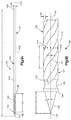
- a soft tissue displacer tool 1 00 in accordance with one embodiment can include a shaft 105 having a shaft body 107.
- the shaft body 107 can be elongate generally along a central axis 110, which can be linear as illustrated, or otherwise shaped as desired.
- the shaft body 107 defines a proximal end 120 and a distal end 130 that is spaced from the proximal end 120 along the central axis.
- the shaft body 107 can further include a central location 135 that is disposed between the proximal end 120 and distal end 130 and is spaced approximately equidistant from the proximal end 120 and the distal end 130.
- the central location 135 can be located on the central axis 110.
- proximal and derivatives thereof are used herein to refer to a direction from the distal end 130 toward the proximal end 120, and the term “distal” and derivatives thereof are used herein to refer to a direction from the proximal end 120 toward the distal end 130.
- the shaft body 107 can be shaped substantially cylindrically as illustrated in Fig. 1A , or can assume other shapes, such as a polyhedron, as desired.
- the shaft body 107 can define an outer surface 109 that extends about the central axis 110.
- the shaft body 107 can have any length (L1) and diameter (D1) suitable for insertion through soft tissue and at least to the bone of a patient.
- the length (L1) and diameter (D1) can be chosen based on the size and location of the bone to be addressed in the surgical procedure. That is, for example, the length (L1) can be from about 3 inches to about 12 inches, preferably from about 5 to about 10 inches; and the diameter (D1) can be from about 0.05 inches to about 0.5 inches, preferably from about 0.075 inches to about 0.25 inches.
- a shaft body 107 to be used in a rotator cuff repair can have a length (L1) that is in a range of from about 5 inches to about 9 inches, preferably from about 6.5 to about 8 inches, or that is about 7-7.5 inches.
- a shaft body 107 to be used in a rotator cuff repair can have a diameter (D1) that is in a range of from about 0.10 inches to about 0.14 inches, or from about 0.11 inches to about 0.13 inches, or that is about 0.12 inches.
- the shaft 105 can further define at least one groove 140 that extends into the shaft body 107, for instance into the outer surface 109 toward the central axis 110.
- the outer surface 109 is substantially smooth between the groove sections 140.
- the outer surface 109 can be configured as one or more protrusions, for example wide threads, such that the groove 140 is defined between adjacent ones of the protrusions.
- the groove 140 can terminate at a location between the outer surface 109 and the central axis 110.
- the groove 140 is inclined with respect to a plane 113 that is normal to the central axis 110 and the groove 140 revolves about the central axis 110.
- the groove 140 extends along the outer surface 109, for instance circumferentially, as it travels along the proximal and distal directions.
- the groove 140 as the groove 140 travels along the proximal direction, the groove can extend clockwise about the central axis 110 with respect to a proximally-oriented view from the distal end 130.
- the groove 140 can extend clockwise about the central axis 110 with respect to a distally-oriented view from the proximal end 120.
- the groove 140 can alternatively extend counter-clockwise about the central axis 110 with respect to a proximally-oriented view from the distal end 130 as the groove 140 travels along the proximal direction.
- the groove 140 is a helical spiral shape along the shaft 105.
- the shaft 105 can include a plurality of the grooves 140 that are circumferentially spaced, for instance equidistantly or variably, from each other along the outer surface 109. While the shaft 105 is illustrated as including two grooves 140 spaced 180 degrees from each other about the central axis 110, the shaft 105 can include as many grooves 140 as desired, such as one, two, three, four, or more grooves, that is one or a plurality of grooves. Each of the plurality of grooves 140 can be constructed as described with respect to the groove 140 herein.
- the groove 140 terminates at a first or proximal end 145 and a second or distal end 150.
- the second end 150 is spaced apart from the first end 145 in the distal direction, and the first end 145 is spaced from the second end 150 in the proximal direction.
- the second end 150 can further be spaced from the distal end 130 of the shaft body 107 along the proximal direction, for instance at a location between the distal end 130 and the central location 135.
- the distance the second end 150 is spaced from the distal end 130 of the shaft body 107 can be chosen based on the application of the soft tissue displacement tool.
- the second end 150 will be from about 0,05 inches to about 1.0 inch, preferably from about 0.1 inches to about 0.8 inches, and more preferably from about 0.2 inches to about 0.3 inches.
- the distance the second end 150 is spaced from the distal end 130 of the shaft body 107 can be in a range of from about 0.05 inch to about 0.8 inches, or from about 0.1 inches to about 0.5 inches, or about 0.25 inches.
- the first end 145 can be disposed anywhere along the shaft body 107 as desired at a location proximal of the second end 150.
- the first end of the groove 145 can be disposed between the central location 135 and the second end of the groove 150, can be disposed between the central location 135 and the proximal end of the shaft 120, and can further extend to the proximal end of the shaft 1 20.
- the distance along the central axis 110 between the proximal end 145 and the distal end 150 of the groove can define a groove length (L2) that can be chosen based on the application of the soft tissue displacement tool. In most applications, the groove length (L2) will be from about 0.5 inches to about 10 inches, preferably from about 0.7 inches to about 5 inches, and more preferably from about 0.7 inches to about 4 inches.
- a shaft body 107 can have a groove length (L2) that is in a range of from about 1 inch to about 1.4 inches, or from about 1.1 inches to about 1.3 inches, or that is about 1.2 inches.
- the groove 140 can be configured as a helix having a consistent pitch P throughout at least a portion, such as an entirety, of its length. In other embodiments the groove 140 revolves around the central axis 110 and may have a varying pitch P. As used herein, a "helix" or a “helical” groove can have a consistent pitch P or a varying pitch P.
- the shaft body 107 can define an interface 141 between the groove 140 and the outer surface 109.
- the interface 141 can define an angle, a beveled edge, a rounded edge, or any suitably constructed structure that provides an interface between the outer surface 109 and the groove 140.
- the groove 140 can have a generally consistent depth D2, which can be measured from the outer surface 109 toward the central axis 110, and width W that can be measured from a first side of the groove 140 to a second side of the groove 140 along a direction that is about the central axis 110 along a plane that is oriented normal to the central axis 110.
- the depth D2 can be chosen based on the size and location within the body of the patient of the bone to be recessed. For example, the depth D2 can be from about 0.0005 inches to about 0.05 inches, and the width can be from about 0.01 to about 0.50 inches.
- the groove 140 can have a depth D2 that is in a range of from about 0.005 inch to about 0.025 inch, or from about 0.010 inch to about 0.020 inch, or that is approximately 0.014 inch, with a width W of from about 0.08 to about 0.24 inches. It should be appreciated that the groove 140 can define any suitable alternative depth D2 and width W as desired.
- the groove 140 can have a curved cross-section, or a cross-section made up of a plurality of intersecting planes (e.g. rectangular or square).
- a shaft body 107 to be used in a rotator cuff repair can have a groove 140 having a curved cross-section with a radius of curvature that is in a range of from about 0,01 inch to about 0.1 inch, or that is about 0.06 inch.
- the distal end 130 of the shaft body 107 can include a tip 155.
- the tip 155 can be tapered in the distal direction. In some embodiments the tip 155 terminates in a point, while in other embodiments the tip 155 can be blunt.
- the tip 155 can be conical, pyramidal, polyhedral, or shaped like a frustum. The foregoing example tip shapes are illustrative and are not meant to be limiting.
- the tip 155 can be configured to be driven into or through soft tissue or bone, such as through the cortical wall of the bone and into the cancellous portion of the bone, as is described in more detail below.
- the tip 155 can have an angle ( ⁇ ) with respect to the central axis 110 and a length (L3) that can independently be chosen based on the application of the soft tissue displacement tool.
- a shaft body 107 to be used in a rotator cuff repair can have a tip angled with respect to the central axis ( ⁇ ) that is in a range of from about 20° to about 40°, from about 25° to about 35°, or that is about 30°.
- a shaft body 107 to be used in a rotator cuff repair can have a tip 155 having a length (L3) that is in a range of from about 0. 10 inch to about 0.30 inch, or that is about 0.18 inch.
- the shaft body 107 further defines a cutting edge 160 which is distal facing.
- the cutting edge 160 can define a shoulder that extends out with respect to the tip 155, for instance out from the tip 155, in a direction substantially normal to the central axis 110, which can also be referred to as a radial direction, regardless of whether the shaft body 107 is cylindrical or alternatively shaped.
- the cutting edge 160 can be annular or segmented as desired. Alternatively, the cutting edge 160 can extend out from the tip at any angle as desired with respect to the central axis 110.
- the cutting edge 160 can have a circular or polygonal perimeter extending about the central axis 110.
- the cutting edge 160 can be straight, jagged, serrated, or another configuration that is capable of cutting, punching, or otherwise being driven through soft tissue or bone, such as the cortical wall of the bone.
- the shaft 105 can also carry a channel 165 that extends into the shaft body 107, for instance into the outer surface 109 toward the central axis 110.
- the channel 165 can terminate at a location between the outer surface 109 and the central axis 110.
- the channel 165 can extend along the outer surface 109 about the central axis 110, for instance circumferentially about the central axis 110. As the channel 165 revolves about the central axis 110, the channel 165 does not translate along the central axis 110 in either the proximal or distal directions.
- the channel can be disposed proximal of the tip 155 and distal of the groove 140 (e.g., between the tip 155 and the groove 140).
- the channel 165 can be disposed adjacent, for instance proximal, with respect to the cutting edge 160, such that the cutting edge 160 is disposed between the tip 155 and the channel 165.
- the channel 165 can have a curved cross-section, or a cross-section made up of a plurality of intersecting planes.
- the channel 165 can be designed to have the same or different depth and/or cross-sectional shape with respect to the groove 140.
- a shaft body 107 to be used in a rotator cuff repair can have a channel 165 having a curved cross-section with a radius of curvature that is in a range from about 0.01 inch to about 0.1 inch, or that is about 0.06 inch.
- the shaft body 107 can carry a visual marking 119 that is located a predetermined distance from the distal end 130 along the central axis 110, which can be a linear distance as described above.
- the distance of the visual marking 119 from the distal end 130 of the shaft can be predetermined based on the clinical situation in which the particular soft tissue displacer tool is designed to be used and can vary depending on the intended use of the soft tissue displacer tool. Ordinarily, once the visual marking 119 is positioned it is not varied by the user of the soft tissue displacer tool 100.
- the predetermined distance can correspond to the preferred depth of a recess formed in the bone when the depth indicated is driven into the bone, as is described in more detail below.
- a medical professional can use the visual marking 119 as a guide to gauge the depth to which the soft tissue displacer tool 100 has been inserted in the bone, and thereby gauge the depth of the recess in the bone into which the soft tissue displacer tool 100 has been inserted.
- the shaft 105 can also carry a second channel 167 that extends into the shaft body 107, for instance into the outer surface 109 toward the central axis 110.
- the channel 167 can terminate at a location between the outer surface 109 and the central axis 110.
- the channel 167 can extend along the outer surface 109 about the central axis 110, for instance circumferentially about the central axis 110. As the channel 167 revolves about the central axis 110, the channel 167 does not translate along the central axis 110 in either the proximal or distal directions.
- the channel can be disposed proximal of the groove 140 (e.g., between the groove 140 and the proximal end 120).
- the channel 167 can have a curved cross-section, or a cross-section made up of a plurality of intersecting planes.
- the channel 167 can be designed to have the same or different depth and/or cross-sectional shape with respect to the groove 140.
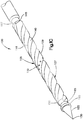
- the shaft 105 can be inserted through the soft tissue 170 and at least to the outer surface of the bone 175.
- the shaft for instance at distal end 130, which can be a tapered, or pointed, tip, can be driven through the soft tissue 170 toward the bone that underlies the soft tissue 170.
- the distal end 130 of the shaft body 107 can be driven into the underlying bone 175.
- the distal end 130 can be punched, or driven substantially linearly without rotation, into the bone under a distally directed force that is applied to the shaft.
- the force can be an impacting force, such as that from a hammer or mallet, or can be a substantially constant force.
- the distal end 130 can be rotated in one direction, or back-and-forth, as a distal force applied to the shaft 105 drives the distal end 130 into the bone.
- Frictional forces between the outer surface 109 of the shaft body 107 and the soft tissue 1 70 can cause the soft tissue 170 to be carried with the shaft 105 toward, for instance to, the outer surface of the bone 175, which can obscure a view between the soft tissue and the bone (either by naked eye or by a surgical camera system).
- the bone depth is achieved when the visual marking 119 is in a predetermined proximity with respect to the bone, for instance inline with or adjacent the outer surface of the bone. Accordingly, it is desirable to provide an unobstructed view to the outer surface of the bone so as to ensure visibility of the visual marking 119 when the visual marking 119 is in the predetermined proximity with the outer surface of the bone.
- the shaft 105 can be rotated, which causes at least a portion of at least one of the grooves 140 to at least partially receive at least a portion of the soft tissue 170. Due to the incline of the grooves 140, as the shaft 105 is rotated, the grooves 140 apply a proximally-directed force to the soft tissue that cause the soft tissue 170 to move along the proximal direction with respect to the bone 175. Thus, the rotation of the shaft 105 causes the grooves 140 to lift the soft tissue 170 off of the bone 175.
- the grooves 140 are inclined such that by rotating the shaft 105 the one or more locations on the grooves 140 that contact the soft tissue 170 move along the shaft 105 in the proximal direction away from the bone 175. As illustrated in Fig. 2C , clockwise rotation of the shaft 105 causes the grooves 140 to lift the soft tissue 170 away from the bone 175.
- the grooves 140 can be configured such that counter-clockwise rotation of the shaft 105 causes the grooves 140 to lift the soft tissue 170 away from the bone 175.
- the portion of the shaft 105 disposed between the soft tissue 170 and the bone 175 can be visualized and the position of the visual marking 119 with respect to the bone 175 observed when the marking is on the portion of the shaft body 107 that is disposed between the soft tissue 1 70 and the bone 175.
- the soft tissue can be raised a sufficient height to allow a field of view to the visual marking.
- the soft tissue 170 can be raised until it is tented, or pulled taut, to restore the field of view of the visual marking 119, while in other patients the visual marking 119 can be visualized without raising the soft tissue 170 to the point of being tented.
- the visual marking 119 can be disposed between the soft tissue and the bone, and thus visually accessed by a camera or other imaging instrument whose field of view is between the soft tissue and the bone. A determination can be made as to the position of the visual marking 119 with respect to the predetermined proximity with respect to the bone 175. If the marking 119 is not yet in the predetermined proximity with respect to the bone 175, the shaft 105 can be further driven into the soft tissue 170 and into the bone 175, as illustrated in Fig. 2D . Referring to Fig. 2E , the shaft 105 can again be rotated to raise the soft tissue 170 away from the bone 175 as described above.
- the shaft 105 can be continuously driven into the bone 175 and subsequently rotated to lift the soft tissue 170 away from the bone 175 as desired until the visual marking 119 is in the predetermined proximity with respect to the bone 175, thereby indicating that the shaft 105 has been driven to the predetermined depth.
- a camera or other instrumentality can be used to assist the medical professional in viewing the visual marking.
- the shaft 105 can be removed from the bone 175 by application of pulling or turning, or a combination of pulling and turning forces, as illustrated in Fig. 2F .
- the shaft 105 can be configured for removal by rotating the shaft 105 in a counterclockwise direction as viewed from the proximal end 120 toward the distal end 130, or can be configured for removal by rotating the shaft in a clockwise direction as viewed from the proximal end 120 toward the distal end 130.
- the soft tissue displacer tool can be constructed in accordance with any suitable alternative embodiment as desired.
- the shaft of the soft tissue displacer tool can be solid and have a pointed tip
- the shaft of the soft tissue displacer tool can also be cannulated and used in combination with a guidewire or separate recess forming instrument.
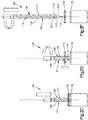
- the soft tissue displacer tool 200 can include a cannulated shaft 205 that can be constructed as described above, but is further configured to be cannulated; thus the tool 200 can receive a guidance member 285 that can pierce soft tissue, and in some embodiments, can be inserted into underlying bone.
- the guidance member 285 can be configured to form a recess in the underlying bone (e.g., a self-cutting K-wire), or can be configured to be secured in a previously-formed recess in the underlying bone (e.g, a K-wire used after a drilling procedure), or can be configured to abut the bone (e.g., a trocar).
- the guidance member 285 can be advanced at least to the surface of the bone, and in some embodiments advanced or secured in the underlying bone, and the soft tissue displacer tool 200 can be rotated in the manner described above so as to lift the soft tissue off the bone in order to provide visual access to the visual marking 219.
- the shaft 205 can thus include a shaft body 207.
- the shaft body 207 can be elongate generally along a central axis 210, which can be linear as illustrated, or otherwise shaped as desired.
- the shaft body 207 defines a proximal end 220, a distal end 230 that is spaced from the proximal end 220 along the central axis.
- the shaft body 207 can further include a central location 235 that is disposed between the proximal end 220 and distal end 230 and is spaced approximately equidistant from the proximal end 220 and the distal end 230.
- the central location 235 can be located on the central axis 210.
- the term "proximal” and derivatives thereof are used herein to refer to a direction from the distal end 130 toward the proximal end 220, and the term “distal” and derivatives thereof are used herein to refer to a direction from the proximal end 220 toward the distal end 230.
- the shaft body 207 can be shaped substantially cylindrically as illustrated in Fig. 3A , or can assume other shapes, such as a polyhedron, as desired.
- the shaft body 207 can define an outer surface 209 that extends about the central axis 210.
- the shaft body 207 can have any length (L4) and diameter (D3) suitable for insertion through soft tissue and at least to the bone of a patient and these dimensions can be the same as described above for length (L1) and diameter (D1).
- the shaft 205 can be made of any suitable material, including metals and plastics, and preferably is a transparent or translucent material, including, but not limited to, polycarbonate, acrylic, and polystyrene.
- the shaft 205 can further define at least one groove 240 that extends into the shaft body 207, for instance into the outer surface 209 toward the central axis 210.
- the groove 240 can be similar to the groove 140 described above, and can take the same general shape, pattern, and number as the groove 140 described above.
- the distance along the central axis 210 between the proximal end 245 and the distal end 250 of the groove can define a groove length (L5) that can be chosen based on the application of the soft tissue displacement tool.
- the length (L5) can be the same as described above for length (L2), and the depth (D4) can be the same as above depth (D2).
- the distal end 230 of the shaft body 207 can include a tip 255.
- the tip 255 can be tapered in the distal direction.
- the tip 255 can be blunt and in some embodiments the tip 255 is shaped like a frustum or a polyhedron.
- the foregoing example tip shapes are illustrative and are not meant to be limiting.
- the tip 255 can be configured to be driven into or through soft tissue, as is described in more detail below.
- the tip 255 can have an angle ( ⁇ ) with respect to the central axis 210 and a length (L6) that can independently be chosen based on the application of the soft tissue displacement tool.
- a shaft body 207 to be used in a rotator cuff repair can have a tip angled with respect to the central axis ( ⁇ ) in a range of from about 20° to about 40°, in a range from about 25° to about 35°, or is about 30°.
- a shaft body 207 to be used in a rotator cuff repair can have a tip 155 having a length (L6) that is in a range of from about 0.01 inch to about 0.10 inch, or is about 0.06 inch.
- the shaft body 207 further defines a cutting edge 260 which is distal facing.
- the cutting edge 260 can define a shoulder that extends out with respect to the tip 255, for instance out from the tip 255, in a direction substantially normal to the central axis 210, which can also be referred to as a radial direction, regardless of whether the shaft body 207 is cylindrical or alternatively shaped.
- the cutting edge 260 can be annular or segmented as desired. Alternatively, the cutting edge 260 can extend out from the tip at any angle as desired with respect to the central axis 210.
- the cutting edge 260 can have a circular or polygonal perimeter extending about the central axis 210.
- the cutting edge 260 can be straight, jagged, serrated, or another configuration that is capable of cutting, punching, or otherwise being driven through soft tissue or bone such as the cortical wall of the bone.
- the shaft 205 can also carry a channel 265 that extends into the shaft body 207, for instance into the outer surface 209 toward the central axis 210.
- the channel 265 can terminate at a location between the outer surface 209 and the central axis 210.
- the channel 265 can extend along the outer surface 209 about the central axis 210, for instance circumferentially about the central axis 210. As the channel 265 revolves about the central axis 210, the channel 265 does not translate along the central axis 210 in either the proximal or distal directions.
- the channel can be disposed proximal of the tip 255 and distal of the groove 240 (e.g., between the tip 255 and the groove 240).
- the channel 265 can be disposed adjacent, for instance proximal, with respect to the cutting edge 260, such that the cutting edge 260 is disposed between the tip 255 and the channel 265.
- the channel 265 can have a can have a curved cross-section, or a cross-section made up of a plurality of planes.
- the channel 265 can be designed to have the same or different depth and/or cross-sectional shape with respect to the groove 240.
- a shaft body 207 to be used in a rotator cuff repair can have a channel 265 having a curved cross-section with a radius of curvature that is in a range from about 0.01 inch to about 0.1 inch, or about 0.06 inch.
- the shaft body 207 can carry a visual marking 219 that is located a predetermined distance from the distal end 230 along the central axis 210, which can be a linear distance as described above.
- the distance of the visual marking 219 from the distal end 230 of the shaft can be predetermined based on the clinical situation in which the particular soft tissue displacer tool is designed to be used and can vary depending on the intended use of the soft tissue displacer tool. Ordinarily, once the visual marking 219 is positioned it is not varied by the user of the soft tissue displacer tool 200.
- the predetermined distance can correspond to the preferred depth of a recess formed in the bone when the depth indicated is driven into the bone, as is described in more detail below.
- a medical professional can use the visual marking 219 as a guide to gauge the depth to which the soft tissue displacer tool 200 has been inserted in the bone, and thereby gauge the depth of the recess in the bone into which the soft tissue displacer tool 200 has been inserted.
- a guidance member 285 or other instrument received in the opening 280 of the shaft body 207 can carry a visual marking 219 that is located a pretermitted distance from the distal end of the guidance member 285 or other instrument.
- the shaft 205 can also carry a second channel 267 that extends into the shaft body 207, for instance into the outer surface 209 toward the central axis 210.
- the channel 267 can terminate at a location between the outer surface 209 and the central axis 210.
- the channel 267 can extend along the outer surface 209 about the central axis 210, for instance circumferentially about the central axis 210. As the channel 267 revolves about the central axis 210, the channel 267 does not translate along the central axis 210 in either the proximal or distal directions.
- the channel can be disposed proximal of the tip 255 and the groove 240 (e.g., between the groove 240 and the proximal end 220).
- the channel 267 can have a can have a curved cross-section, or a cross-section made up of a plurality of intersecting planes.
- the channel 267 can be designed to have the same or different depth and/or cross-sectional shape with respect to the groove 240.
- the shaft 205 can be cannulated so as to define an opening 280 that extends through the shaft body 207 generally along the central axis 210 from the proximal end 220 to the distal end 230.
- the opening 280 can further be positioned centrally with respect to the central axis 210, and can be sized and shaped as desired so as to receive the guidance member 285 therein.
- the shaft body 207 includes an inner surface 283 that extends from the proximal end 220 to the distal end 230 and defines the opening 280.
- the inner surface 283 can be shaped substantially cylindrically, or can assume other shapes, such as a polyhedron, as desired.
- the inner surface 283 can have a diameter (D5) that is sized smaller than the diameter of the shaft body (D3) and large enough to receive a guidance member 285.
- a shaft body 207 to be used in a rotator cuff repair can have an opening 280 defined by an inner surface 283 having a diameter (D5) that is in the range of from about 0.05 inch to about 0.15 inch or from about 0,05 inch to about 0.10 inch or that is about 0.07 inch.
- the soft tissue displacer tool 200 can also include a guidance member 285 that has a proximal end, a distal end, and is elongated along a central axis, which can be linear as illustrated, or otherwise shaped as desired.
- the guidance member 285 can be constructed as desired, and can be configured to be advanced at least to the surface of the underlying bone, and in some embodiments advanced or secured in the underlying bone.
- the guidance member 285 constructed in accordance with one embodiment can be configured as a K-wire (Kirschner wire) 287 having a body 289 and a tip 291 that extends distally from the body 289.
- the tip 291 can be tapered along the distal direction, and can define a pointed tip as desired.
- the K-wire can have a pointed tip that is capable of piercing soft tissue and/or bone, such as the cortical wall of the bone, and being driven into the cancellous portion of the bone.
- the K-wire tip shape can include a diamond tip or a trocar tip.
- the K-wire 287 can further be threaded at a location proximal to the tip 291, or can be smooth or devoid of threading. Accordingly, an opening can be pre-drilled in the bone, and the K-wire 287 can be inserted into the pre-created opening. If threaded, the K-wire can be rotated so as to threadedly attach to the bone.
- a drilling instrument can pre-create the opening.
- the tip 291 of the K-wire 287 can be driven into the bone so as to create the opening. If threaded, the K-wire 287 can be subsequently rotated so as to threadedly attach to the bone.
- the K-wire 287 can be secured in the bone at a location that defines the recess to be formed.
- the guidance member 285 can be configured to be advanced into the bone, for example it can form an opening in the bone, or can be secured in the bone, for instance within a pre-drilled opening.
- the guidance member 285, such as the K-wire 287, of the soft tissue displacer tool 200 can be introduced through the soft tissue and advanced or secured into the bone.
- the K-wire 287 can be advanced or secured in a pre-drilled opening or driven into the bone in the manner described above. If the K-wire is unthreaded, the K-wire 287 can be press-fit in the bone.
- the K-wire 287 can be implanted by any method known in the art, including driving, hammering, drilling, or screwing.
- the K-wire 287 can be advanced into or secured to the bone either while disposed in the opening 280 of the shaft 205, or outside the shaft 205.
- the method can include the step of placing the shaft 205 over the K-wire 287 such that the K-wire 287 extends through the opening 280 before or after advancement or securement of the K-wire 287 to the bone. Once the K-wire 287 has been advanced into or secured to the bone and further extends through the opening 280, the shaft 205 can be inserted through the soft tissue and to the bone along the K-wire 287.
- the shaft 205 can be driven into the bone to a sufficient depth such that the groove 240 is aligned with the soft tissue. Accordingly, the shaft 205 can be rotated in the manner described above with respect to the soft tissue displacer tool 100 so as to lift the soft tissue off of the bone. The position of the visual marking 219 can thus be assessed in the manner described above, and the shaft can further be driven into the bone and subsequently rotated so as to lift the soft tissue away from the bone as many times as desired so as to visually confirm that the soft tissue displacer tool 200 has been driven into the bone at the predetermined depth.
- a camera or other imaging system whose field of view is between the bone and the lifted soft tissue can provide an image of the visual marking 219 and the bone.
- the shaft 205 can be removed by pulling or turning, or a combination of pulling and turning as described above.
- the K-wire 287 can be removed from the bone before or after removal of the shaft 205.
- the guidance member 285 constructed in accordance with another embodiment can be configured as a trocar 293 having a body 295 and a tip 297 that extends distally from the body 295.
- the tip 297 can be tapered along the distal direction, and can define a pointed tip as desired.
- the tip 297 can be pointed and capable of piercing soft tissue.
- the tip 297 can be capable of piercing the bone, such as the cortical wall of the bone, and being driven into the cancellous portion of the bone. Accordingly, the tip 297 of the trocar 293 can be driven into the soft tissue and the trocar 293 can further be driven at least to the surface of the bone or be driven into the bone to the desired depth.
- the trocar itself can be solid or can be cannulated to receive a guidewire. It should be appreciated that the trocar can carry the visual marking 219, and the shaft shaft 205 can be transparent or translucent so that the visual marking 219 carried by the trocar 293 is visible through the shaft 205. Alternatively, the trocar 293 can be used to pierce the soft tissue and carry the shaft 205 at least to the surface of the underlying bone.
- the trocar 293 can be removed from the opening 280 of the shaft 205 and an instrument, such as a bone punch, can be inserted into the opening 280 of the shaft 205.
- the instrument such as a bone punch, can carry a visual marking 219 that is a predetermined distance from the distal end of the instrument.
- the shaft 205 can be made of a transparent or translucent material, including, but not limited to, polycarbonate, acrylic, and polystyrene, such that the visual marking 219 on the instrument can be seen through the shaft 205 when the instrument 285 is disposed within the opening 280 of the shaft 205.
- the trocar 293 can be driven into the bone as described above.
- the trocar 293 can be driven into the bone before or after insertion of the trocar 293 into the opening 280. If the trocar 293 is driven into the bone prior to insertion into the opening 280, the shaft 205 can then be placed over the trocar 293 such that the trocar extends at least into or through the opening 280. Next, the shaft 205 can be driven along the trocar 293 until the distal end 230 is placed against the bone. Alternatively, the trocar 293 can be driven through the soft tissue and at least to the surface of the bone while disposed in the opening 280 of shaft 205.
- Frictional forces between the outer surface 209 of the shaft 205 and the soft tissue can cause the soft tissue to be carried with the shaft 205 to the outer surface of the bone.
- the soft tissue can be lifted away from the bone by rotating the shaft 205 in the manner described above until a desired field of view of the camera or other imaging device is directed between the soft tissue and the bone.
- the trocar can be removed from the opening 280 of the shaft 205 and an instrument can be inserted into the opening 280 of the shaft 205.
- the trocar 293 can be removed from the opening 280 of the shaft 205 before or after the shaft 205 has been rotated to raise the soft tissue away from the bone.
- the shaft 205 can be rotated to raise the soft tissue if the soft tissue is positioned so as to interfere with the field of vision of marking 219 on the instrument.
- the instrument can be driven into the bone and because the shaft 205 is in contact with the soft tissue, and the instrument is driven through the shaft 205, the step of driving the instrument into the bone does not cause the soft tissue to be carried toward the bone.
- the instrument and the shaft 205 can then be removed from the bone.
- the soft tissue displacer tools 100 and 200 can be used to form a recess in a bone and to measure the depth of a recess in a bone in accordance with other methods. For instance, in instances where the soft tissue has been severed, and thus will not be carried along with the shaft toward the outer surface of the bone, the soft tissue displacer tool can be inserted into the bone and a medical professional can view the visual marking to determine the depth to which the soft tissue displacer tool has been inserted, and thereby determine the depth of the recess in the bone. The soft tissue displacer tool can be driven further into the bone and the visual marking viewed repeatedly until the soft tissue displacer tool has been inserted into the bone a depth commensurate with the predetermined distance between the visual marking and the distal end 130, 230.
- the medical professional will first complete the tear and insert the soft tissue displacer tool 100, 200 through the tear and into the bone.
- the medical professional can view the visual marking to determine the depth of the recess in the bone.
- the medical professional can repeat the steps of driving the soft tissue displacer tool into the bone and, if a visual marking is present, viewing the visual marking.
- the soft tissue displacer tool can be removed by pulling or turning, or a combination of pulling and turning. As illustrated in Fig.
- a soft tissue displacer tool 100 having a groove 140 that is clockwise as viewed proximally from the distal end can be removed by rotating the bone recess indicator in a counterclockwise direction as viewed proximally from the distal end, either alone or in combination with the application of a proximally directed force to the shaft.
- a soft tissue displacer tool having a groove that is left-handed is well suited for removal by rotating the bone recess indicator in a counterclockwise direction as viewed from the proximal end.
Landscapes
- Health & Medical Sciences (AREA)
- Life Sciences & Earth Sciences (AREA)
- Surgery (AREA)
- Molecular Biology (AREA)
- General Health & Medical Sciences (AREA)
- Biomedical Technology (AREA)
- Heart & Thoracic Surgery (AREA)
- Medical Informatics (AREA)
- Nuclear Medicine, Radiotherapy & Molecular Imaging (AREA)
- Animal Behavior & Ethology (AREA)
- Engineering & Computer Science (AREA)
- Public Health (AREA)
- Veterinary Medicine (AREA)
- Dentistry (AREA)
- Oral & Maxillofacial Surgery (AREA)
- Orthopedic Medicine & Surgery (AREA)
- Surgical Instruments (AREA)
Applications Claiming Priority (2)
| Application Number | Priority Date | Filing Date | Title |
|---|---|---|---|
| US13/835,763 US10238400B2 (en) | 2013-03-15 | 2013-03-15 | Soft tissue displacer tool with inclined groove and methods |
| PCT/US2014/021501 WO2014149912A1 (en) | 2013-03-15 | 2014-03-07 | Soft tissue displacer tool and with inclined groove and methods |
Publications (2)
| Publication Number | Publication Date |
|---|---|
| EP2967527A1 EP2967527A1 (en) | 2016-01-20 |
| EP2967527B1 true EP2967527B1 (en) | 2018-04-25 |
Family
ID=50391451
Family Applications (1)
| Application Number | Title | Priority Date | Filing Date |
|---|---|---|---|
| EP14714042.0A Not-in-force EP2967527B1 (en) | 2013-03-15 | 2014-03-07 | Soft tissue displacer tool with inclined groove |
Country Status (8)
| Country | Link |
|---|---|
| US (1) | US10238400B2 (pt) |
| EP (1) | EP2967527B1 (pt) |
| JP (1) | JP6740124B2 (pt) |
| CN (1) | CN105050507B (pt) |
| AU (1) | AU2014237700B2 (pt) |
| BR (1) | BR112015022901A2 (pt) |
| CA (1) | CA2906358C (pt) |
| WO (1) | WO2014149912A1 (pt) |
Families Citing this family (9)
| Publication number | Priority date | Publication date | Assignee | Title |
|---|---|---|---|---|
| US20160278789A1 (en) * | 2015-03-24 | 2016-09-29 | Flower Orthopedics Corporation | Cannulated Countersink and Depth Gauge Multi-Instrument and Method of Determining Required Screw Length Using the Same |
| WO2018081632A1 (en) | 2016-10-27 | 2018-05-03 | C.R. Bard, Inc. | Intraosseous access device |
| CN112568975A (zh) | 2019-09-27 | 2021-03-30 | 巴德阿克塞斯系统股份有限公司 | 恒定扭矩骨内进入装置及其方法 |
| CN112568961A (zh) | 2019-09-27 | 2021-03-30 | 巴德阿克塞斯系统股份有限公司 | 骨内装置的自动推进特征 |
| EP4031027A4 (en) | 2019-09-27 | 2023-09-13 | Bard Access Systems, Inc. | VARIED OPERATING MECHANISMS FOR INTRAOSSEOUS ACCESS MEDICAL DEVICES AND ASSOCIATED METHODS |
| CN113520512A (zh) | 2020-04-21 | 2021-10-22 | 巴德阿克塞斯系统股份有限公司 | 可重复使用的推动启动式骨内进入装置 |
| US20220015865A1 (en) * | 2020-07-15 | 2022-01-20 | Daniel S. Kim | Guided implant drill system and methods of use |
| CN114903553A (zh) | 2021-02-08 | 2022-08-16 | 巴德阿克塞斯系统股份有限公司 | 骨内进入系统和用于钻入穿过骨骼的方法 |
| JP2023044382A (ja) * | 2021-09-17 | 2023-03-30 | 株式会社フジフレックスマーケティング | 手術用ガイドピン |
Family Cites Families (22)
| Publication number | Priority date | Publication date | Assignee | Title |
|---|---|---|---|---|
| US4537185A (en) * | 1983-06-10 | 1985-08-27 | Denis P. Stednitz | Cannulated fixation screw |
| US4713004A (en) | 1986-09-04 | 1987-12-15 | Vent Plant Corporation | Submergible screw-type dental implant and method of utilization |
| US4830000A (en) * | 1987-12-31 | 1989-05-16 | Aspen Laboratories, Inc. | Surgical drill |
| JP2876415B2 (ja) | 1990-01-30 | 1999-03-31 | 株式会社スズキエンジニアリング | 医療用ドリルと内視鏡付きドリル装置 |
| US5013317A (en) * | 1990-02-07 | 1991-05-07 | Smith & Nephew Richards Inc. | Medical drill assembly transparent to X-rays and targeting drill bit |
| US5098435A (en) | 1990-11-21 | 1992-03-24 | Alphatec Manufacturing Inc. | Cannula |
| US5242443A (en) * | 1991-08-15 | 1993-09-07 | Smith & Nephew Dyonics, Inc. | Percutaneous fixation of vertebrae |
| US5374270A (en) * | 1991-12-13 | 1994-12-20 | David A. McGuire | Device and method for insertion of guide pin |
| US5676545A (en) | 1994-08-15 | 1997-10-14 | Jones; Shedrick D. | Method and apparatus for implantation |
| US5833628A (en) * | 1996-04-24 | 1998-11-10 | Yuan; Hansen | Graduated bone graft harvester |
| US5686673A (en) * | 1996-07-15 | 1997-11-11 | Kabis; Thomas W. | Sampler |
| US6395011B1 (en) * | 1998-07-17 | 2002-05-28 | Johnson & Johnson | Method and apparatus for harvesting and implanting bone plugs |
| US6197031B1 (en) * | 1999-09-08 | 2001-03-06 | Bristol-Myers Squibb Co. | Threaded drill/IM rod |
| US6312432B1 (en) | 2000-03-02 | 2001-11-06 | Nemco Medical, Inc. | Bone drill |
| JP3940002B2 (ja) | 2002-02-22 | 2007-07-04 | 久弥 岡崎 | 穿孔方向可変ドリル刃 |
| WO2004073544A2 (en) * | 2003-02-22 | 2004-09-02 | Peter Morris Stevens | Cannulated drill pin |
| US7048477B2 (en) * | 2003-06-30 | 2006-05-23 | I.D.M.S., L.L.C. | Drill measurement stops |
| US8221423B2 (en) * | 2006-03-28 | 2012-07-17 | Warsaw Orthopedic, Inc. | Osteochondral plug graft harvesting instrument and kit |
| KR100630304B1 (ko) | 2006-04-04 | 2006-10-02 | 안상훈 | 임플란트 시술용 확공기 |
| KR100930911B1 (ko) | 2007-11-22 | 2009-12-10 | 오스템임플란트 주식회사 | 다단구조를 이용한 치과용 임플란트 드릴 |
| WO2011049817A1 (en) | 2009-10-20 | 2011-04-28 | Smith & Nephew, Inc. | Connector assembly |
| CN202270078U (zh) * | 2011-09-28 | 2012-06-13 | 上海理工大学 | 微创植牙手术钻 |
-
2013
- 2013-03-15 US US13/835,763 patent/US10238400B2/en active Active
-
2014
- 2014-03-07 CN CN201480016083.1A patent/CN105050507B/zh not_active Expired - Fee Related
- 2014-03-07 WO PCT/US2014/021501 patent/WO2014149912A1/en active Application Filing
- 2014-03-07 CA CA2906358A patent/CA2906358C/en active Active
- 2014-03-07 EP EP14714042.0A patent/EP2967527B1/en not_active Not-in-force
- 2014-03-07 AU AU2014237700A patent/AU2014237700B2/en not_active Ceased
- 2014-03-07 BR BR112015022901A patent/BR112015022901A2/pt not_active Application Discontinuation
- 2014-03-07 JP JP2016500778A patent/JP6740124B2/ja not_active Expired - Fee Related
Non-Patent Citations (1)
| Title |
|---|
| None * |
Also Published As
| Publication number | Publication date |
|---|---|
| US10238400B2 (en) | 2019-03-26 |
| US20140276833A1 (en) | 2014-09-18 |
| JP2016511079A (ja) | 2016-04-14 |
| CA2906358C (en) | 2021-03-02 |
| CA2906358A1 (en) | 2014-09-25 |
| EP2967527A1 (en) | 2016-01-20 |
| AU2014237700B2 (en) | 2019-03-07 |
| AU2014237700A1 (en) | 2015-10-29 |
| BR112015022901A2 (pt) | 2017-07-18 |
| CN105050507B (zh) | 2019-01-15 |
| CN105050507A (zh) | 2015-11-11 |
| JP6740124B2 (ja) | 2020-08-12 |
| WO2014149912A1 (en) | 2014-09-25 |
Similar Documents
| Publication | Publication Date | Title |
|---|---|---|
| EP2967527B1 (en) | Soft tissue displacer tool with inclined groove | |
| KR101236499B1 (ko) | 캐뉼러가 형성된 체결부재를 위한 조정가능한 도구 | |
| AU2003290901B2 (en) | Compression bone fragment wire | |
| EP2624762B1 (en) | Bone marrow harvesting device having flexible needle | |
| US11452532B2 (en) | Parallel guide for surgical implants | |
| US11058437B2 (en) | Systems and methods for pedicle screw implantation using flexible drill bit | |
| BR112019021980A2 (pt) | estrias angulares em parafusos ósseos com cânula | |
| US10792053B2 (en) | Press system for setting a surgical device | |
| JP2016190079A (ja) | Peekを多く含む骨ねじ | |
| KR20070009539A (ko) | 캐뉼러가 형성된 체결기구 시스템 | |
| US20150272645A1 (en) | Universal length screw design and cutting instrument | |
| US20170020534A1 (en) | Fluted bone awl and method of use | |
| US10285745B2 (en) | Orthopedic screws | |
| US6004321A (en) | Cannulated screw retraction apparatus and method of retraction | |
| US20150157310A1 (en) | Rotary medical anchor, and medical kit comprising said anchor | |
| US20200107869A1 (en) | Devices and methods for repairing bone fractures | |
| KR20190108269A (ko) | 척추 수술 장치 | |
| CN106725712B (zh) | 关节突上钉器械及关节突上钉方法 | |
| CN1935092A (zh) | 一种经皮导引骨扩孔工具装置及方法 | |
| JP2017046926A (ja) | 脊椎固定術用穿孔器の挿入位置指示具及びガイド装置 | |
| MX2012014151A (es) | Instrumentos para la cirugia de columna espinal mini-invasiva y sus aplicaciones. |
Legal Events
| Date | Code | Title | Description |
|---|---|---|---|
| PUAI | Public reference made under article 153(3) epc to a published international application that has entered the european phase |
Free format text: ORIGINAL CODE: 0009012 |
|
| 17P | Request for examination filed |
Effective date: 20150918 |
|
| AK | Designated contracting states |
Kind code of ref document: A1 Designated state(s): AL AT BE BG CH CY CZ DE DK EE ES FI FR GB GR HR HU IE IS IT LI LT LU LV MC MK MT NL NO PL PT RO RS SE SI SK SM TR |
|
| AX | Request for extension of the european patent |
Extension state: BA ME |
|
| DAX | Request for extension of the european patent (deleted) | ||
| STAA | Information on the status of an ep patent application or granted ep patent |
Free format text: STATUS: EXAMINATION IS IN PROGRESS |
|
| 17Q | First examination report despatched |
Effective date: 20170309 |
|
| RIC1 | Information provided on ipc code assigned before grant |
Ipc: A61B 17/02 20060101AFI20170922BHEP Ipc: A61B 17/16 20060101ALN20170922BHEP Ipc: A61B 17/3205 20060101ALN20170922BHEP Ipc: A61B 17/32 20060101ALN20170922BHEP |
|
| GRAP | Despatch of communication of intention to grant a patent |
Free format text: ORIGINAL CODE: EPIDOSNIGR1 |
|
| STAA | Information on the status of an ep patent application or granted ep patent |
Free format text: STATUS: GRANT OF PATENT IS INTENDED |
|
| INTG | Intention to grant announced |
Effective date: 20171103 |
|
| RIN1 | Information on inventor provided before grant (corrected) |
Inventor name: LARSEN, SCOTT P. Inventor name: SINGHATAT, WAMIS |
|
| GRAS | Grant fee paid |
Free format text: ORIGINAL CODE: EPIDOSNIGR3 |
|
| GRAA | (expected) grant |
Free format text: ORIGINAL CODE: 0009210 |
|
| STAA | Information on the status of an ep patent application or granted ep patent |
Free format text: STATUS: THE PATENT HAS BEEN GRANTED |
|
| AK | Designated contracting states |
Kind code of ref document: B1 Designated state(s): AL AT BE BG CH CY CZ DE DK EE ES FI FR GB GR HR HU IE IS IT LI LT LU LV MC MK MT NL NO PL PT RO RS SE SI SK SM TR |
|
| REG | Reference to a national code |
Ref country code: GB Ref legal event code: FG4D |
|
| REG | Reference to a national code |
Ref country code: CH Ref legal event code: EP |
|
| REG | Reference to a national code |
Ref country code: CH Ref legal event code: NV Representative=s name: E. BLUM AND CO. AG PATENT- UND MARKENANWAELTE , CH Ref country code: AT Ref legal event code: REF Ref document number: 992005 Country of ref document: AT Kind code of ref document: T Effective date: 20180515 |
|
| REG | Reference to a national code |
Ref country code: IE Ref legal event code: FG4D |
|
| REG | Reference to a national code |
Ref country code: DE Ref legal event code: R096 Ref document number: 602014024407 Country of ref document: DE |
|
| REG | Reference to a national code |
Ref country code: NL Ref legal event code: MP Effective date: 20180425 |
|
| REG | Reference to a national code |
Ref country code: LT Ref legal event code: MG4D |
|
| PG25 | Lapsed in a contracting state [announced via postgrant information from national office to epo] |
Ref country code: NL Free format text: LAPSE BECAUSE OF FAILURE TO SUBMIT A TRANSLATION OF THE DESCRIPTION OR TO PAY THE FEE WITHIN THE PRESCRIBED TIME-LIMIT Effective date: 20180425 |
|
| PG25 | Lapsed in a contracting state [announced via postgrant information from national office to epo] |
Ref country code: ES Free format text: LAPSE BECAUSE OF FAILURE TO SUBMIT A TRANSLATION OF THE DESCRIPTION OR TO PAY THE FEE WITHIN THE PRESCRIBED TIME-LIMIT Effective date: 20180425 Ref country code: PL Free format text: LAPSE BECAUSE OF FAILURE TO SUBMIT A TRANSLATION OF THE DESCRIPTION OR TO PAY THE FEE WITHIN THE PRESCRIBED TIME-LIMIT Effective date: 20180425 Ref country code: LT Free format text: LAPSE BECAUSE OF FAILURE TO SUBMIT A TRANSLATION OF THE DESCRIPTION OR TO PAY THE FEE WITHIN THE PRESCRIBED TIME-LIMIT Effective date: 20180425 Ref country code: BG Free format text: LAPSE BECAUSE OF FAILURE TO SUBMIT A TRANSLATION OF THE DESCRIPTION OR TO PAY THE FEE WITHIN THE PRESCRIBED TIME-LIMIT Effective date: 20180725 Ref country code: FI Free format text: LAPSE BECAUSE OF FAILURE TO SUBMIT A TRANSLATION OF THE DESCRIPTION OR TO PAY THE FEE WITHIN THE PRESCRIBED TIME-LIMIT Effective date: 20180425 Ref country code: NO Free format text: LAPSE BECAUSE OF FAILURE TO SUBMIT A TRANSLATION OF THE DESCRIPTION OR TO PAY THE FEE WITHIN THE PRESCRIBED TIME-LIMIT Effective date: 20180725 Ref country code: SE Free format text: LAPSE BECAUSE OF FAILURE TO SUBMIT A TRANSLATION OF THE DESCRIPTION OR TO PAY THE FEE WITHIN THE PRESCRIBED TIME-LIMIT Effective date: 20180425 |
|
| PG25 | Lapsed in a contracting state [announced via postgrant information from national office to epo] |
Ref country code: GR Free format text: LAPSE BECAUSE OF FAILURE TO SUBMIT A TRANSLATION OF THE DESCRIPTION OR TO PAY THE FEE WITHIN THE PRESCRIBED TIME-LIMIT Effective date: 20180726 Ref country code: HR Free format text: LAPSE BECAUSE OF FAILURE TO SUBMIT A TRANSLATION OF THE DESCRIPTION OR TO PAY THE FEE WITHIN THE PRESCRIBED TIME-LIMIT Effective date: 20180425 Ref country code: LV Free format text: LAPSE BECAUSE OF FAILURE TO SUBMIT A TRANSLATION OF THE DESCRIPTION OR TO PAY THE FEE WITHIN THE PRESCRIBED TIME-LIMIT Effective date: 20180425 Ref country code: RS Free format text: LAPSE BECAUSE OF FAILURE TO SUBMIT A TRANSLATION OF THE DESCRIPTION OR TO PAY THE FEE WITHIN THE PRESCRIBED TIME-LIMIT Effective date: 20180425 |
|
| REG | Reference to a national code |
Ref country code: AT Ref legal event code: MK05 Ref document number: 992005 Country of ref document: AT Kind code of ref document: T Effective date: 20180425 |
|
| PG25 | Lapsed in a contracting state [announced via postgrant information from national office to epo] |
Ref country code: PT Free format text: LAPSE BECAUSE OF FAILURE TO SUBMIT A TRANSLATION OF THE DESCRIPTION OR TO PAY THE FEE WITHIN THE PRESCRIBED TIME-LIMIT Effective date: 20180827 |
|
| REG | Reference to a national code |
Ref country code: DE Ref legal event code: R097 Ref document number: 602014024407 Country of ref document: DE |
|
| PG25 | Lapsed in a contracting state [announced via postgrant information from national office to epo] |
Ref country code: SK Free format text: LAPSE BECAUSE OF FAILURE TO SUBMIT A TRANSLATION OF THE DESCRIPTION OR TO PAY THE FEE WITHIN THE PRESCRIBED TIME-LIMIT Effective date: 20180425 Ref country code: RO Free format text: LAPSE BECAUSE OF FAILURE TO SUBMIT A TRANSLATION OF THE DESCRIPTION OR TO PAY THE FEE WITHIN THE PRESCRIBED TIME-LIMIT Effective date: 20180425 Ref country code: CZ Free format text: LAPSE BECAUSE OF FAILURE TO SUBMIT A TRANSLATION OF THE DESCRIPTION OR TO PAY THE FEE WITHIN THE PRESCRIBED TIME-LIMIT Effective date: 20180425 Ref country code: DK Free format text: LAPSE BECAUSE OF FAILURE TO SUBMIT A TRANSLATION OF THE DESCRIPTION OR TO PAY THE FEE WITHIN THE PRESCRIBED TIME-LIMIT Effective date: 20180425 Ref country code: EE Free format text: LAPSE BECAUSE OF FAILURE TO SUBMIT A TRANSLATION OF THE DESCRIPTION OR TO PAY THE FEE WITHIN THE PRESCRIBED TIME-LIMIT Effective date: 20180425 Ref country code: AT Free format text: LAPSE BECAUSE OF FAILURE TO SUBMIT A TRANSLATION OF THE DESCRIPTION OR TO PAY THE FEE WITHIN THE PRESCRIBED TIME-LIMIT Effective date: 20180425 |
|
| PG25 | Lapsed in a contracting state [announced via postgrant information from national office to epo] |
Ref country code: SM Free format text: LAPSE BECAUSE OF FAILURE TO SUBMIT A TRANSLATION OF THE DESCRIPTION OR TO PAY THE FEE WITHIN THE PRESCRIBED TIME-LIMIT Effective date: 20180425 |
|
| PLBE | No opposition filed within time limit |
Free format text: ORIGINAL CODE: 0009261 |
|
| STAA | Information on the status of an ep patent application or granted ep patent |
Free format text: STATUS: NO OPPOSITION FILED WITHIN TIME LIMIT |
|
| 26N | No opposition filed |
Effective date: 20190128 |
|
| PG25 | Lapsed in a contracting state [announced via postgrant information from national office to epo] |
Ref country code: SI Free format text: LAPSE BECAUSE OF FAILURE TO SUBMIT A TRANSLATION OF THE DESCRIPTION OR TO PAY THE FEE WITHIN THE PRESCRIBED TIME-LIMIT Effective date: 20180425 |
|
| PG25 | Lapsed in a contracting state [announced via postgrant information from national office to epo] |
Ref country code: MC Free format text: LAPSE BECAUSE OF FAILURE TO SUBMIT A TRANSLATION OF THE DESCRIPTION OR TO PAY THE FEE WITHIN THE PRESCRIBED TIME-LIMIT Effective date: 20180425 |
|
| PG25 | Lapsed in a contracting state [announced via postgrant information from national office to epo] |
Ref country code: LU Free format text: LAPSE BECAUSE OF NON-PAYMENT OF DUE FEES Effective date: 20190307 Ref country code: AL Free format text: LAPSE BECAUSE OF FAILURE TO SUBMIT A TRANSLATION OF THE DESCRIPTION OR TO PAY THE FEE WITHIN THE PRESCRIBED TIME-LIMIT Effective date: 20180425 |
|
| REG | Reference to a national code |
Ref country code: BE Ref legal event code: MM Effective date: 20190331 |
|
| PG25 | Lapsed in a contracting state [announced via postgrant information from national office to epo] |
Ref country code: IE Free format text: LAPSE BECAUSE OF NON-PAYMENT OF DUE FEES Effective date: 20190307 |
|
| PG25 | Lapsed in a contracting state [announced via postgrant information from national office to epo] |
Ref country code: BE Free format text: LAPSE BECAUSE OF NON-PAYMENT OF DUE FEES Effective date: 20190331 |
|
| PG25 | Lapsed in a contracting state [announced via postgrant information from national office to epo] |
Ref country code: TR Free format text: LAPSE BECAUSE OF FAILURE TO SUBMIT A TRANSLATION OF THE DESCRIPTION OR TO PAY THE FEE WITHIN THE PRESCRIBED TIME-LIMIT Effective date: 20180425 |
|
| PG25 | Lapsed in a contracting state [announced via postgrant information from national office to epo] |
Ref country code: MT Free format text: LAPSE BECAUSE OF NON-PAYMENT OF DUE FEES Effective date: 20190307 |
|
| PGFP | Annual fee paid to national office [announced via postgrant information from national office to epo] |
Ref country code: FR Payment date: 20210210 Year of fee payment: 8 Ref country code: IT Payment date: 20210211 Year of fee payment: 8 Ref country code: CH Payment date: 20210317 Year of fee payment: 8 |
|
| PG25 | Lapsed in a contracting state [announced via postgrant information from national office to epo] |
Ref country code: CY Free format text: LAPSE BECAUSE OF FAILURE TO SUBMIT A TRANSLATION OF THE DESCRIPTION OR TO PAY THE FEE WITHIN THE PRESCRIBED TIME-LIMIT Effective date: 20180425 |
|
| PGFP | Annual fee paid to national office [announced via postgrant information from national office to epo] |
Ref country code: DE Payment date: 20210224 Year of fee payment: 8 |
|
| PG25 | Lapsed in a contracting state [announced via postgrant information from national office to epo] |
Ref country code: IS Free format text: LAPSE BECAUSE OF FAILURE TO SUBMIT A TRANSLATION OF THE DESCRIPTION OR TO PAY THE FEE WITHIN THE PRESCRIBED TIME-LIMIT Effective date: 20180825 |
|
| PG25 | Lapsed in a contracting state [announced via postgrant information from national office to epo] |
Ref country code: HU Free format text: LAPSE BECAUSE OF FAILURE TO SUBMIT A TRANSLATION OF THE DESCRIPTION OR TO PAY THE FEE WITHIN THE PRESCRIBED TIME-LIMIT; INVALID AB INITIO Effective date: 20140307 |
|
| PGFP | Annual fee paid to national office [announced via postgrant information from national office to epo] |
Ref country code: GB Payment date: 20210224 Year of fee payment: 8 |
|
| PG25 | Lapsed in a contracting state [announced via postgrant information from national office to epo] |
Ref country code: MK Free format text: LAPSE BECAUSE OF FAILURE TO SUBMIT A TRANSLATION OF THE DESCRIPTION OR TO PAY THE FEE WITHIN THE PRESCRIBED TIME-LIMIT Effective date: 20180425 |
|
| REG | Reference to a national code |
Ref country code: DE Ref legal event code: R119 Ref document number: 602014024407 Country of ref document: DE |
|
| REG | Reference to a national code |
Ref country code: CH Ref legal event code: PL |
|
| GBPC | Gb: european patent ceased through non-payment of renewal fee |
Effective date: 20220307 |
|
| PG25 | Lapsed in a contracting state [announced via postgrant information from national office to epo] |
Ref country code: LI Free format text: LAPSE BECAUSE OF NON-PAYMENT OF DUE FEES Effective date: 20220331 Ref country code: GB Free format text: LAPSE BECAUSE OF NON-PAYMENT OF DUE FEES Effective date: 20220307 Ref country code: FR Free format text: LAPSE BECAUSE OF NON-PAYMENT OF DUE FEES Effective date: 20220331 Ref country code: DE Free format text: LAPSE BECAUSE OF NON-PAYMENT OF DUE FEES Effective date: 20221001 Ref country code: CH Free format text: LAPSE BECAUSE OF NON-PAYMENT OF DUE FEES Effective date: 20220331 |
|
| PG25 | Lapsed in a contracting state [announced via postgrant information from national office to epo] |
Ref country code: IT Free format text: LAPSE BECAUSE OF NON-PAYMENT OF DUE FEES Effective date: 20220307 |