EP2967262B1 - Schaumspender mit einem porösen schäumungselement - Google Patents
Schaumspender mit einem porösen schäumungselement Download PDFInfo
- Publication number
- EP2967262B1 EP2967262B1 EP14764518.8A EP14764518A EP2967262B1 EP 2967262 B1 EP2967262 B1 EP 2967262B1 EP 14764518 A EP14764518 A EP 14764518A EP 2967262 B1 EP2967262 B1 EP 2967262B1
- Authority
- EP
- European Patent Office
- Prior art keywords
- liquid
- air
- foaming
- piston
- porous
- Prior art date
- Legal status (The legal status is an assumption and is not a legal conclusion. Google has not performed a legal analysis and makes no representation as to the accuracy of the status listed.)
- Active
Links
- 238000005187 foaming Methods 0.000 title claims description 119
- 239000006260 foam Substances 0.000 title claims description 51
- 239000007788 liquid Substances 0.000 claims description 98
- 239000011148 porous material Substances 0.000 claims description 45
- 230000007423 decrease Effects 0.000 claims description 11
- 239000000463 material Substances 0.000 claims description 10
- 230000004913 activation Effects 0.000 claims description 8
- 239000000203 mixture Substances 0.000 claims description 8
- 238000011144 upstream manufacturing Methods 0.000 claims description 7
- 238000004519 manufacturing process Methods 0.000 claims description 4
- 230000003213 activating effect Effects 0.000 claims description 2
- 230000008901 benefit Effects 0.000 description 3
- 239000000344 soap Substances 0.000 description 3
- 230000009471 action Effects 0.000 description 2
- 239000000443 aerosol Substances 0.000 description 2
- 230000006835 compression Effects 0.000 description 1
- 238000007906 compression Methods 0.000 description 1
- 230000003247 decreasing effect Effects 0.000 description 1
- 238000000034 method Methods 0.000 description 1
- 230000008569 process Effects 0.000 description 1
- 230000004044 response Effects 0.000 description 1
- 230000007704 transition Effects 0.000 description 1
Images


Classifications
-
- A—HUMAN NECESSITIES
- A47—FURNITURE; DOMESTIC ARTICLES OR APPLIANCES; COFFEE MILLS; SPICE MILLS; SUCTION CLEANERS IN GENERAL
- A47K—SANITARY EQUIPMENT NOT OTHERWISE PROVIDED FOR; TOILET ACCESSORIES
- A47K5/00—Holders or dispensers for soap, toothpaste, or the like
- A47K5/14—Foam or lather making devices
- A47K5/16—Foam or lather making devices with mechanical drive
-
- A—HUMAN NECESSITIES
- A47—FURNITURE; DOMESTIC ARTICLES OR APPLIANCES; COFFEE MILLS; SPICE MILLS; SUCTION CLEANERS IN GENERAL
- A47K—SANITARY EQUIPMENT NOT OTHERWISE PROVIDED FOR; TOILET ACCESSORIES
- A47K5/00—Holders or dispensers for soap, toothpaste, or the like
- A47K5/14—Foam or lather making devices
-
- B—PERFORMING OPERATIONS; TRANSPORTING
- B05—SPRAYING OR ATOMISING IN GENERAL; APPLYING FLUENT MATERIALS TO SURFACES, IN GENERAL
- B05B—SPRAYING APPARATUS; ATOMISING APPARATUS; NOZZLES
- B05B11/00—Single-unit hand-held apparatus in which flow of contents is produced by the muscular force of the operator at the moment of use
- B05B11/01—Single-unit hand-held apparatus in which flow of contents is produced by the muscular force of the operator at the moment of use characterised by the means producing the flow
- B05B11/10—Pump arrangements for transferring the contents from the container to a pump chamber by a sucking effect and forcing the contents out through the dispensing nozzle
- B05B11/1087—Combination of liquid and air pumps
-
- B—PERFORMING OPERATIONS; TRANSPORTING
- B05—SPRAYING OR ATOMISING IN GENERAL; APPLYING FLUENT MATERIALS TO SURFACES, IN GENERAL
- B05B—SPRAYING APPARATUS; ATOMISING APPARATUS; NOZZLES
- B05B7/00—Spraying apparatus for discharge of liquids or other fluent materials from two or more sources, e.g. of liquid and air, of powder and gas
- B05B7/0018—Spraying apparatus for discharge of liquids or other fluent materials from two or more sources, e.g. of liquid and air, of powder and gas with devices for making foam
- B05B7/0025—Spraying apparatus for discharge of liquids or other fluent materials from two or more sources, e.g. of liquid and air, of powder and gas with devices for making foam with a compressed gas supply
- B05B7/0031—Spraying apparatus for discharge of liquids or other fluent materials from two or more sources, e.g. of liquid and air, of powder and gas with devices for making foam with a compressed gas supply with disturbing means promoting mixing, e.g. balls, crowns
- B05B7/0037—Spraying apparatus for discharge of liquids or other fluent materials from two or more sources, e.g. of liquid and air, of powder and gas with devices for making foam with a compressed gas supply with disturbing means promoting mixing, e.g. balls, crowns including sieves, porous members or the like
Definitions
- This disclosure relates to foam dispensers and in particular foam dispensers having a porous foaming element wherein the air and liquid mix within the porous foaming element.
- Foam dispensers are well known and widely used commercially. A wide variety of foam dispensers have been developed. In particular, a number of non-aerosol foam dispensers that use unpressurised liquid containers have been developed, such as the dispenser described in US 2007/0023454 A1 , that discloses a foaming assembly according to the preamble of claim 1. The advantage of foam dispensers over soap dispensers is that for each wash less soap is used.
- One way to reduce the costs for manufacturing is to reduce the number of components. Accordingly an embodiment that reduces the number of parts would be advantageous.
- the invention achieves these advantages by a foaming assembly according to claim 1 and/or a method of making foam according to claim 17.
- the foaming assembly includes a porous foaming element, a liquid chamber and an air chamber.
- the porous foaming element has an air inlet, a liquid inlet and an outlet.
- the porous foaming element has at least two zones of different pore sizes.
- the liquid chamber is in flow communication with the porous foaming element.
- the liquid chamber has a liquid volume that is movable between an at rest position to an activation position.
- the air chamber is in flow communication with the porous foaming element.
- the air chamber has an air volume that is movable between an at rest position to an activation position. Liquid and air are forced into the porous foaming element under pressure and air from the air inlet and liquid from the liquid inlet mix in the porous foaming element to form foam which exits through the outlet.
- a dispenser may include a foaming assembly and a liquid container.
- the porous foaming element may have a smaller pore size zone and a larger pore size zone.
- the smaller pore size zone may be downstream of the larger pore size zone.
- the smaller pore size zone may be upstream of the larger pore size zone.
- the porous foaming element has a generally bow tie shape in cross section.
- the foaming assembly may include a foam cone, a piston and a bottle seal and wherein the piston and bottle seal define the liquid chamber, the foam cone, bottle seal and piston define the air chamber and movement inwardly of the foam cone into the bottle seal decreases the liquid volume of the liquid chamber and the air chamber thereby forcing under pressure air and liquid into the porous foaming element.
- the porous foaming element may be positioned in the foam cone between the foam cone and the piston.
- the porous foaming element may be made of compressible material and a smaller pore size zone is where the compressible material is more compressed than in a larger pore size zone.
- the shape of the porous foaming element may be defined by the geometry of the piston and the foam cone.
- the foaming assembly may include a piston dome, a liquid and air bore and a main pump body and the piston dome, liquid and air bore and main body define a liquid chamber, the piston dome and liquid and air bore define the air chamber and movement inwardly of the piston dome into the main body decreases the liquid volume of the liquid chamber and the air chamber thereby forcing under pressure air and liquid into the porous foaming element.
- the main pump body may include an exit nozzle and the porous foaming element is positioned in the exit nozzle between the liquid chamber and a venturi ring.
- the shape of the porous foaming element may be defined by the geometry of the exit nozzle and the venturi ring.
- the foaming assembly may include a pump head, a bottle cap, an air piston, a piston and a main body and the main body and piston define the liquid chamber and the pump head, bottle cap, air piston, piston and main body define the air chamber movement inwardly of the pump head into the main body decreases the liquid volume of the liquid chamber and the air chamber thereby forcing, under pressure, air and liquid into the porous foaming element.
- the shape of the porous foaming element may be defined by the geometry of the air piston and the pump head.
- a foam dispenser includes a liquid container and a porous foaming element.
- the foam dispenser may further include a housing having an actuator wherein activating the actuator causes the air chamber and the liquid chamber to move between the at rest position to the activation position.
- the housing may further include at least one sensor and the actuator is activated responsive to the sensor sensing the presence of a user.
- a method of making foam including the steps of forcing air and liquid under pressure into a porous foaming element having at least two zones of different pore sizes wherein they mix to form foam which exits through the outlet.
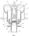
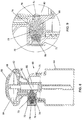
- Dispenser 10 includes a foaming assembly 12 connected to a liquid container 13.
- the liquid container 13 is an unpressurized liquid container.
- the foaming assembly 12 includes foam cone 14, a piston 16 and a bottle seal 18.
- the piston 16 and bottle seal 18 define a liquid chamber 20.
- the foam cone 14, bottle seal 18 and piston 16 define an air chamber 22.
- the liquid chamber 20 is a central liquid chamber and the air chamber 22 is an annular air chamber.
- the foam cone 16 moves relative to the bottle seal 18.
- the piston 16 is operably connected to the foam cone 14 with a press fit.
- An O-ring 24 slides between the piston 16 and the bottle seal 18 and provides a liquid seal therebetween.
- the liquid container 13 is in flow communication with the liquid chamber 20.
- a bottle seal valve 28 controls the inlet 30 of the liquid chamber 20.
- a top hat valve 32 controls the outlet 34 of the liquid chamber 20.
- a mixing chamber 37 is located between the piston 16 and the foam cone 14.
- the mixing chamber 37 defines an interior volume which is filled with a porous foaming element 36.
- the mixing chamber extends from an upstream end to a downstream end and the upstream end is spaced apart from the downstream end.
- the porous material extends from the upstream end to the downstream end of the porous foaming element.
- the mixing chamber 37 has an air inlet 38, a liquid inlet 40 and an outlet 41.
- the air inlet 38, the liquid inlet 40 and the outlet 41 are in flow communication with the porous foaming element 36 such that air and liquid mix in the mixing chamber 37 and mix within the porous foaming element.
- the air inlet 38 and liquid inlet 40 are spaced apart.
- the porous foaming element 36 has zones of different porosity.
- the porous foaming element 36 has a smaller pore size zone 44 and a larger pore size zone 46.
- the porous foaming element 36 may be compressible material or it may be manufactured such that the pore size varies as prescribed.
- the compressible material may be sponge material.
- pore size decreases the foam quality changes. It has been observed that as pore size decreases the resultant foam appears smoother or richer and thus would be considered better quality foam. As air and liquid are forced under pressure through the porous foaming element 36 the foam quality improves.
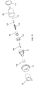
- the zones of different porosity are defined by the geometry of the piston 16 and the foam cone 14. Compression of the porous foaming element 36 is achieved during assembly. As shown in figures 3 to 5 , a variety of different configurations may be constructed such that the porous foaming element 36 has a compressed zone 44 having smaller pores and an expanded zone 46 with larger pores.
- the mixing chamber 37 filled with the porous foaming element 36 has a generally bow tie shape as shown in figure 3 wherein the larger pore size zone 46 is around the outside and the smaller pore size zone 44 is in the center.
- the mixing chamber 37 filled with the porous foaming element 36 may be shaped into an unclaimed half bow tie at the bottom as shown in figure 4 wherein the small pore size zone 44 is downstream of the larger pore size zone 46.
- the mixing chamber 37 filled with the porous foaming element 36 may be shaped into an unclaimed half bow tie at the top as shown in figure 5 , wherein the small pore size zone 44 is upstream of the larger pore size zone 46. Note that where the porous foaming element is made from compressible material there may be a gradual transition of pore size between the large pore size zone 46 to the small pore size zone 44.
- the foam cone 14 moves inwardly relative to the bottle seal 18 thus moving between an at rest position to an activation position decreasing the liquid volume of the liquid chamber 20 and the air chamber 22 thus pressurizing the liquid and air therein and forcing the liquid and air under pressure into the mixing chamber 37 filled with the porous foaming element 36.
- This embodiment is similar to that shown in US patent 8,104,650 issued to Lang et al. on January 31, 2012 .
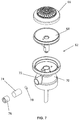
- One advantage of the mixing chamber 37 filled with the porous foaming element 36 is that it acts as both a foaming element and an anti-drip element. Thus in the embodiment described above a number of elements may be reduced. Comparing a prior art foaming component 49 shown in figure 6 to the embodiment described above, most of the components are the same except that it does not include the porous foaming element 36. Rather it includes the upstream gauze tube 50 having large gauze pores, downstream gauze tube 52 having smaller gauze pores and venturi ring 54, all of which are not needed in the embodiments of the present disclosure.
- the foam cone 14, valve 32, piston 16, O-ring 24, bottle seal valve 28 and bottle seal 18 are similar to those described above with regard to foaming assembly 12.
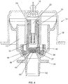
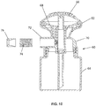
- dispenser 60 includes a pump or foaming assembly 62 and a liquid container 64.
- Pump 62 includes a piston dome 66, a liquid and air bore 68 and a main pump body 70.
- the main pump body 70 includes an exit nozzle 72.
- a mixing chamber 73 is defined by the exit nozzle and a venturi ring 76.
- a porous foaming element 74 is positioned in the mixing chamber 73 of the exit nozzle 72.
- a venturi ring 76 is downstream of the porous foaming element 74.
- a valve 78 is positioned in exit nozzle 72 to selectively open and close the liquid outlet 82 of liquid chamber 80.
- the liquid and air bore 68 and main body 70 define a liquid chamber 80.
- the piston dome 66 and liquid and air bore 68 define the air chamber 84. Movement inwardly of the piston dome 66 into the main body 70 decreases the liquid volume of the liquid chamber 80 and the air chamber 84 thereby forcing under pressure air and liquid through the liquid outlet 82 and the air outlet 83 into the porous foaming element 74. Air and liquid mix together and then foam within the porous element 74.
- the porous foaming element 74 is positioned in the exit nozzle between the liquid chamber 80 and the venturi ring 76 and fills the area therebetween.
- the porous foaming element 74 is made of compressible material and a smaller pore size zone 86 is where the compressible material is more compressed than in a larger pore size zone 88.
- the geometry of the porous foaming element 74 is defined by the geometry of the exit nozzle 72 and the venturi ring 76. In the assembly process the porous foaming element 74 is positioned in the nozzle 72 and then the venturi ring 76 is inserted into the nozzle 72.
- venturi ring 76 The geometry of the venturi ring 76 is configured to create a compressed area such that there is a smaller pore size zone 86 and a larger pore size zone 88 as best seen in figure 9 .
- the porous foaming element is manufactured to have different pour sizes and to fill the area between the liquid chamber 80 and the venturi ring 76.
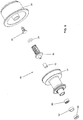
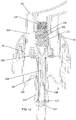
- FIG. 11 another example of a porous foaming assembly 90 is similar to that shown in US patent 5,443,569 issued to Uehira et al. on August 22, 1995 but modified to include a porous foaming element 106.
- the porous foaming assembly 90 includes a pump head 92, a bottle cap 94, an air piston 96, a piston 98 and a main body 100.
- the main body 100 and piston 98 define the liquid chamber 102 and the pump head 92, bottle cap 94, air piston 96, piston 98 and main body 100 define the air chamber 104. Movement inwardly of the pump head 92 into the main body 100 decreases the liquid volume of the liquid chamber 102 and the air chamber 104 thereby forcing, under pressure, air and liquid into a porous foaming element 106.
- the porous foaming assembly 90 includes a valve stem 108 and air valve 110, a valve step 112, liquid valve 114 and main body seal 116.
- a spring 118 biases pump head 92 into an at rest position. Moving the pump head 92 into the main body 100 and into an activation position decreases the air volume of the air chamber 104 and liquid chamber 102.
- a mixing chamber 101 is filled with a porous foaming element and the shape of the porous foaming element 106 is defined by the geometry of the air piston 96 and the pump head 92 defining a smaller pore size zone 120 and a larger pore size zone 122.
- dispenser 10 may further include a housing 124.
- the housing 124 has an actuator 126 that engages foam cone 14 such that moving the actuator 126 moves the foam cone 14.
- Housing 124 may include a sensor 128 that activates the sensor response to the sensor sensing the presence of a user.
- the size of the overall space package may be reduced when compared to using a separate mixing chamber and porous media.
- the terms, “comprises” and “comprising” are to be construed as being inclusive and open ended, and not exclusive. Specifically, when used in the specification and claims, the terms, “comprises” and “comprising” and variations thereof mean the specified features, steps or components are included. These terms are not to be interpreted to exclude the presence of other features, steps or components.
- exemplary means “serving as an example, instance, or illustration,” and should not be construed as preferred or advantageous over other configurations disclosed herein.
- the terms “about” and “approximately” are meant to cover variations that may exist in the upper and lower limits of the ranges of values, such as variations in properties, parameters, and dimensions. In one non-limiting example, the terms “about” and “approximately” mean plus or minus 10 percent or less.
- the term “substantially” refers to the complete or nearly complete extent or degree of an action, characteristic, property, state, structure, item, or result.
- an object that is “substantially” enclosed would mean that the object is either completely enclosed or nearly completely enclosed.
- the exact allowable degree of deviation from absolute completeness may in some cases depend on the specific context. However, generally speaking the nearness of completion will be so as to have the same overall result as if absolute and total completion were obtained.
- the use of “substantially” is equally applicable when used in a negative connotation to refer to the complete or near complete lack of an action, characteristic, property, state, structure, item, or result.
Landscapes
- Health & Medical Sciences (AREA)
- Public Health (AREA)
- Engineering & Computer Science (AREA)
- Mechanical Engineering (AREA)
- Containers And Packaging Bodies Having A Special Means To Remove Contents (AREA)
- Closures For Containers (AREA)
- Nozzles (AREA)
Claims (17)
- Schäumungsanordnung (12, 62, 90), umfassend:ein poröses Schäumungselement (36, 74, 106) mit einem Lufteinlass (38), einem Flüssigkeitseinlass (40) und einem Auslass (41), wobei Lufteinlass und Flüssigkeitseinlass voneinander beabstandet sind und das poröse Schäumungselement mindestens zwei Zonen (44, 46, 86, 88) mit unterschiedlichen Porengrößen aufweist;eine Flüssigkeitskammer (20, 80, 102) in Strömungsverbindung mit dem porösen Schäumungselement, wobei die Flüssigkeitskammer ein Flüssigkeitsvolumen aufweist, das zwischen einer Ruheposition und einer Aktivierungsposition beweglich ist;eine Luftkammer (22, 84, 104) in Strömungsverbindung mit dem porösen Schäumungselement, wobei die Luftkammer ein Luftvolumen aufweist, das zwischen einer Ruheposition und einer Aktivierungsposition bewegbar ist;wobei Flüssigkeit und Luft unter Druck in das poröse Schäumungselement gedrückt werden, wobei Luft aus dem Lufteinlass und Flüssigkeit aus dem Flüssigkeitseinlass in dem porösen Schäumungselement vermischt werden, um Schaum zu bilden, der über den Auslass austritt, dadurch gekennzeichnet, dass das poröse Schäumungselement im Querschnitt im allgemeinen zu einer Schleife geformt ist.
- Schäumungsanordnung (12, 62, 90) nach Anspruch 1, wobei das poröse Schäumungselement (36, 74, 106) eine Zone (44, 86) mit geringerer Porengröße und eine Zone (46, 88) mit größerer Porengröße aufweist.
- Schäumungsanordnung (12, 62, 90) nach Anspruch 2, wobei sich die Zone (44, 86) mit geringerer Porengröße stromabwärts von der Zone (44, 88) mit größerer Porengröße befindet.
- Schäumungsanordnung (12, 62, 90) nach Anspruch 2, wobei sich die Zone (44, 86) mit geringerer Porengröße stromaufwärts von der Zone (44, 88) mit größerer Porengröße befindet.
- Schäumungsanordnung nach einem der Ansprüche 1 bis 4, wobei die Schäumungsanordnung ferner einen Schaumkegel (14), einen Kolben (16) und einen Flaschenverschluss (18) aufweist und wobei der Kolben und der Flaschenverschluss die Flüssigkeitskammer (20) definieren, der Schaumkegel, der Flaschenverschluss und der Kolben die Luftkammer (22) definieren und eine Bewegung des Schaumkegels nach innen in den Flaschenverschluss das Flüssigkeitsvolumen der Flüssigkeitskammer und der Luftkammer verringert, wodurch unter Druck Luft und Flüssigkeit in das poröse Schäumungselement (36) gedrückt werden.
- Schäumungsanordnung (12, 62, 90) nach Anspruch 5, wobei das poröse Schäumungselement (36) im Schaumkegel (14) zwischen dem Schaumkegel und dem Kolben (16) angeordnet ist.
- Schäumungsanordnung (12, 62, 90) nach Anspruch 5 oder 6, wobei die Form des porösen Schäumungselements (36) durch die Geometrie des Kolbens (16) und des Schaumkegels (14) definiert ist.
- Schäumungsanordnung (12, 62, 90) nach einem der Ansprüche 1 bis 4, wobei die Schäumungsanordnung ferner einen Kolbenboden (66), eine Flüssigkeits- und Luftbohrung (68) und einen Hauptpumpenkörper (70) aufweist und wobei der Kolbenboden, die Flüssigkeits- und Luftbohrung und der Hauptpumpenkörper die Flüssigkeitskammer (80) definieren, der Kolbenboden und die Flüssigkeits- und Luftbohrung die Luftkammer (84) definieren und eine Bewegung des Kolbenbodens nach innen in den Hauptpumpenkörper hinein das Flüssigkeitsvolumen der Flüssigkeitskammer und der Luftkammer verringert, wodurch unter Druck Luft und Flüssigkeit in das poröse Schäumungselement (74) gedrückt werden.
- Schäumungsanordnung (12, 62, 90) nach Anspruch 8, wobei der Hauptpumpenkörper (70) eine Austrittsdüse (72) aufweist und das poröse Schäumungselement (74) in der Austrittsdüse zwischen der Flüssigkeitskammer (80) und einem Venturi-Ring (76) angeordnet ist.
- Schäumungsanordnung (12, 62, 90) nach Anspruch 9, wobei die Form des porösen Schäumungselements (74) durch die Geometrie der Austrittsdüse (72) und des Venturi-Ringes (76) definiert ist.
- Schäumungsanordnung (12, 62, 90) nach einem der Ansprüche 1 bis 4, wobei die Schäumungsanordnung ferner einen Pumpenkopf (92), einen Flaschendeckel (94), einen Luftkolben (96), einen Flüssigkeitskolben (98) und einen Hauptkörper (100) aufweist, und der Hauptkörper und der Kolben die Flüssigkeitskammer (102) definieren, und der Pumpenkopf, der Flaschendeckel, der Luftkolben, der Kolben und der Hauptkörper die Luftkammer (104) definieren und die Bewegung nach innen vom Pumpenkopf in den Hauptkörper das Flüssigkeitsvolumen der Flüssigkeitskammer und der Luftkammer verringert, wodurch unter Druck Luft und Flüssigkeit in das poröse Schäumungselement (106) gedrückt werden.
- Schäumungsanordnung (12, 62, 90) nach Anspruch 11, wobei die Form des porösen Schäumungselements (106) durch die Geometrie des Luftkolbens (96) und des Pumpenkopfes (92) definiert ist.
- Schäumungsanordnung (12, 62, 90) nach einem der Ansprüche 1 bis 12, wobei das poröse Schäumungselement (106) aus komprimierbarem Material besteht und das komprimierbare Material in einer Zone (44, 86) mit geringerer Porengröße stärker komprimiert wird als in einer Zone (46, 88) mit größerer Porengröße.
- Schaumspender (10, 60), umfassend:
einen Flüssigkeitsbehälter (13, 64); und eine Schäumungsanordnung nach Anspruch 1. - Schaumspender (10, 60) nach Anspruch 14, ferner aufweisend ein Gehäuse (124) mit einem Stellglied (126), wobei das Aktivieren des Stellglieds bewirkt, dass sich die Luftkammer (22, 84, 104) und die Flüssigkeitskammer zwischen der Ruheposition und der Aktivierungsposition bewegen.
- Schaumspender (10, 60) nach Anspruch 15, wobei das Gehäuse (124) ferner mindestens einen Sensor (128) beinhaltet und das Stellglied (126) aktiviert wird, wenn der Sensor die Anwesenheit eines Benutzers erfasst.
- Verfahren zur Herstellung von Schaum, umfassend die Schritte des Hineindrückens von Luft und Flüssigkeit unter Druck in eine Schäumungsanordnung (12, 62, 90) gemäß einem beliebigen vorhergehenden Anspruch, die ein poröses Schäumungselement (36, 74, 106) mit mindestens zwei Zonen (44, 46, 86, 88) mit unterschiedlichen Porengrößen umfasst, worin sie sich vermischen, um Schaum zu bilden, der dann durch den Auslass (41) austritt.
Applications Claiming Priority (2)
| Application Number | Priority Date | Filing Date | Title |
|---|---|---|---|
| US13/842,281 US8820585B1 (en) | 2013-03-15 | 2013-03-15 | Foam dispenser with a porous foaming element |
| PCT/CA2014/050191 WO2014138958A1 (en) | 2013-03-15 | 2014-03-07 | Foam dispenser with a porous foaming element |
Publications (3)
| Publication Number | Publication Date |
|---|---|
| EP2967262A1 EP2967262A1 (de) | 2016-01-20 |
| EP2967262A4 EP2967262A4 (de) | 2016-10-12 |
| EP2967262B1 true EP2967262B1 (de) | 2019-04-17 |
Family
ID=51399846
Family Applications (1)
| Application Number | Title | Priority Date | Filing Date |
|---|---|---|---|
| EP14764518.8A Active EP2967262B1 (de) | 2013-03-15 | 2014-03-07 | Schaumspender mit einem porösen schäumungselement |
Country Status (11)
| Country | Link |
|---|---|
| US (1) | US8820585B1 (de) |
| EP (1) | EP2967262B1 (de) |
| JP (1) | JP6423806B2 (de) |
| CN (2) | CN109567652A (de) |
| AU (1) | AU2014231618B2 (de) |
| BR (1) | BR112015022382B1 (de) |
| CA (1) | CA2900737A1 (de) |
| HK (1) | HK1212576A1 (de) |
| MX (1) | MX362557B (de) |
| SG (1) | SG11201507281RA (de) |
| WO (1) | WO2014138958A1 (de) |
Cited By (4)
| Publication number | Priority date | Publication date | Assignee | Title |
|---|---|---|---|---|
| US11744412B2 (en) | 2021-10-07 | 2023-09-05 | Deb Ip Limited | Dispenser system |
| US11744413B2 (en) | 2021-10-07 | 2023-09-05 | Deb Ip Limited | Dispenser assembly |
| US12185884B2 (en) | 2021-10-07 | 2025-01-07 | Deb Ip Limited | Dispenser |
| USD1061260S1 (en) | 2023-07-18 | 2025-02-11 | S. C. Johnson & Son, Inc. | Dispenser |
Families Citing this family (20)
| Publication number | Priority date | Publication date | Assignee | Title |
|---|---|---|---|---|
| US20140252042A1 (en) * | 2013-03-06 | 2014-09-11 | Georgia-Pacific Consumer Products Lp | Fluid dispenser |
| JP6632369B2 (ja) * | 2014-12-24 | 2020-01-22 | 花王株式会社 | 泡吐出器 |
| US9943196B2 (en) | 2015-11-12 | 2018-04-17 | Gojo Industries, Inc. | Sequentially activated multi-diaphragm foam pumps, refill units and dispenser systems |
| US10065199B2 (en) | 2015-11-13 | 2018-09-04 | Gojo Industries, Inc. | Foaming cartridge |
| US10080466B2 (en) | 2015-11-18 | 2018-09-25 | Gojo Industries, Inc. | Sequentially activated multi-diaphragm foam pumps, refill units and dispenser systems |
| US10080467B2 (en) | 2015-11-20 | 2018-09-25 | Gojo Industries, Inc. | Foam dispensing systems, pumps and refill units having high air to liquid ratios |
| US10080468B2 (en) | 2015-12-04 | 2018-09-25 | Gojo Industries, Inc. | Sequentially activated multi-diaphragm foam pumps, refill units and dispenser systems |
| US10441115B2 (en) | 2016-02-11 | 2019-10-15 | Gojo Industries, Inc. | High quality non-aerosol hand sanitizing foam |
| WO2017139727A1 (en) * | 2016-02-11 | 2017-08-17 | Gojo Industries, Inc. | High quality non-aerosol hand sanitizing foam |
| US10912426B2 (en) | 2016-04-06 | 2021-02-09 | Gojo Industries, Inc. | Sequentially activated multi-diaphragm foam pumps, refill units and dispenser systems |
| US10143339B2 (en) | 2016-04-06 | 2018-12-04 | Gojo Industries, Inc. | Sequentially activated multi-diaphragm foam pumps, refill units and dispenser systems |
| DE102016108447A1 (de) * | 2016-05-06 | 2017-11-09 | S O L O Kleinmotoren Gesellschaft Mit Beschränkter Haftung | Verschäumungseinheit zum Erzeugen von Schaum aus einem Gemisch aus Gas und Flüssigkeit sowie Sprühgerät zum Erzeugen und Verteilen von Schaum |
| GB201702905D0 (en) * | 2017-02-23 | 2017-04-12 | Deb Ip Ltd | Foamable skin and hand cleansing compositions |
| US12433827B2 (en) | 2017-02-23 | 2025-10-07 | Deb Ip Limited | Foamable cleansing compositions |
| US10874262B1 (en) * | 2019-09-25 | 2020-12-29 | Hydrotek Corporation | Soap dispensing nozzle structure |
| CN112716338B (zh) * | 2020-12-28 | 2025-05-09 | 喻建荣 | 一种发泡细密均匀型发泡装置及其发泡方法 |
| USD1047689S1 (en) * | 2021-10-07 | 2024-10-22 | Deb Ip Limited | Container |
| USD1038762S1 (en) * | 2021-10-07 | 2024-08-13 | Deb Ip Limited | Container |
| USD1038763S1 (en) * | 2021-10-07 | 2024-08-13 | Deb Ip Limited | Container |
| WO2024026207A1 (en) * | 2022-07-25 | 2024-02-01 | Gojo Industries, Inc. | Foam dispensers having high air to liquid ratios and foam dispensers that dispense accurate volume doses of foam |
Citations (1)
| Publication number | Priority date | Publication date | Assignee | Title |
|---|---|---|---|---|
| EP2545833A2 (de) * | 2004-05-07 | 2013-01-16 | Deb IP Limited | Schaumreiniger mit suspendierten Teilchen, Herstellungsverfahren dafür und Spender dafür |
Family Cites Families (50)
| Publication number | Priority date | Publication date | Assignee | Title |
|---|---|---|---|---|
| US2593178A (en) | 1948-11-13 | 1952-04-15 | Paul Milton | Washing device |
| US3208958A (en) | 1963-03-04 | 1965-09-28 | Pacific Vegets Le Oil Corp | Method and apparatus for producing plastic foam |
| US4184615A (en) | 1975-04-03 | 1980-01-22 | Wright Hershel E | Foam dispensing device |
| US4018364A (en) * | 1975-04-03 | 1977-04-19 | Hershel Earl Wright | Foam dispensing device |
| US4022351A (en) | 1975-04-03 | 1977-05-10 | Hershel Earl Wright | Foam dispenser |
| US3937364A (en) | 1975-04-03 | 1976-02-10 | Hershel Earl Wright | Foam dispensing device |
| US4068625A (en) | 1976-05-12 | 1978-01-17 | Charles Lester Brown | Engine intake air moisturizer |
| JPS5823415Y2 (ja) * | 1976-05-18 | 1983-05-19 | 株式会社吉野工業所 | 泡用スプレ− |
| FR2610302B1 (fr) | 1987-02-03 | 1989-06-09 | Poizot Francis | Distributeur de mousse |
| US5167798A (en) | 1988-01-27 | 1992-12-01 | Virginia Tech Intellectual Properties, Inc. | Apparatus and process for the separation of hydrophobic and hydrophilic particles using microbubble column flotation together with a process and apparatus for generation of microbubbles |
| US5238155A (en) | 1991-02-11 | 1993-08-24 | Jack W. Kaufman | Foam generating device |
| DE9116615U1 (de) | 1991-08-09 | 1993-04-08 | Eci European Chemical Industries Ltd., Castleblayney | Vorrichtung zur Schaumerzeugung |
| JPH0669161U (ja) * | 1993-03-05 | 1994-09-27 | 大和製罐株式会社 | ポンプ式泡出し容器 |
| JPH0747090Y2 (ja) * | 1993-12-22 | 1995-11-01 | ワコー株式会社 | スポンジたわし |
| US5445288A (en) | 1994-04-05 | 1995-08-29 | Sprintvest Corporation Nv | Liquid dispenser for dispensing foam |
| US5662811A (en) | 1995-03-20 | 1997-09-02 | Revtech Industries, Inc. | Method for creating gas-liquid interfacial contact conditions for highly efficient mass transfer |
| US5649334A (en) | 1996-03-07 | 1997-07-22 | Henriquez; Jorge De Jesus Matias | Water and soap dispensing scrubber apparatus |
| US6082586A (en) | 1998-03-30 | 2000-07-04 | Deb Ip Limited | Liquid dispenser for dispensing foam |
| US6271275B1 (en) | 1998-08-17 | 2001-08-07 | Sealed Air Corp. (Us) | Method and apparatus for producing polyurethane foam |
| GB9912356D0 (en) * | 1999-05-26 | 1999-07-28 | Btg Int Ltd | Generation of microfoam |
| JP4485021B2 (ja) * | 2000-06-09 | 2010-06-16 | 可賀 長谷川 | 発泡洗浄装置 |
| WO2004067188A1 (en) * | 2003-01-30 | 2004-08-12 | Unilever Plc | Foam dispenser |
| US7651992B2 (en) * | 2003-02-28 | 2010-01-26 | The Procter & Gamble Company | Foam-generating kit containing a foam-generating dispenser and a composition containing a high level of surfactant |
| ES2279353T3 (es) * | 2003-02-28 | 2007-08-16 | THE PROCTER & GAMBLE COMPANY | Kit generador de espuma que contiene un dispensador que genera espuma y una composicion que contiene un elevado nivel de tensioactivo. |
| CA2464905C (en) | 2004-03-19 | 2008-12-23 | Hygiene-Technik Inc. | Dual component dispenser |
| JP2006204390A (ja) * | 2005-01-26 | 2006-08-10 | Inoac Corp | 粉石けん用泡立て具 |
| US7770874B2 (en) | 2005-04-22 | 2010-08-10 | Gotohii.com Inc. | Foam pump with spring |
| CA2504989C (en) * | 2005-04-22 | 2013-03-12 | Gotohti.Com Inc. | Stepped pump foam dispenser |
| CA2513181C (en) * | 2005-07-25 | 2012-03-13 | Gotohti.Com Inc. | Antibacterial foam generator |
| US7543722B2 (en) | 2005-09-06 | 2009-06-09 | Joseph S. Kanfer | Foam soap generator and pump |
| US7819289B2 (en) | 2006-04-14 | 2010-10-26 | Joseph S Kanfer | Foam soap generator |
| US7850049B2 (en) * | 2008-01-24 | 2010-12-14 | Gojo Industries, Inc. | Foam pump with improved piston structure |
| US8499981B2 (en) * | 2008-02-08 | 2013-08-06 | Gojo Industries, Inc. | Bifurcated stem foam pump |
| US8313010B2 (en) * | 2008-02-08 | 2012-11-20 | Gojo Industries, Inc. | Bifurcated foam pump assembly |
| WO2009142886A1 (en) | 2008-05-23 | 2009-11-26 | Gojo Industries, Inc. | Foam dispenser with compressible porous mixing element |
| CA2667158A1 (en) * | 2008-05-29 | 2009-11-29 | Gojo Industries, Inc. | Pull actuated foam pump |
| US8104650B2 (en) * | 2008-06-06 | 2012-01-31 | Pibed Ltd. | Anti drip device for liquid dispensers |
| CA2634981C (en) * | 2008-06-12 | 2016-08-09 | Gotohti.Com Inc. | Withdrawal discharging piston pump |
| GB2472235B (en) * | 2009-07-29 | 2011-07-06 | Brightwell Dispensers Ltd | Dispensing device with a disposable pump |
| US8733591B2 (en) | 2009-10-04 | 2014-05-27 | G.A.B. Develoment & Engineering B.V. | Fluid product dispenser with shunting chamber and governing device |
| WO2011064584A1 (en) * | 2009-11-26 | 2011-06-03 | Leafgreen Limited | Manual pump dispenser and a method of manufacturing the same |
| CN201578144U (zh) * | 2009-11-27 | 2010-09-15 | 林添大 | 一种改进的泡沫泵 |
| US8187338B2 (en) * | 2009-12-18 | 2012-05-29 | The Procter & Gamble Company | Foam oxidative hair colorant composition |
| WO2011156556A2 (en) * | 2010-06-10 | 2011-12-15 | Gojo Industries, Inc. | Piezoelectric foaming pump |
| US20120104048A1 (en) * | 2010-10-27 | 2012-05-03 | Hsih Tung Tooling Co.,Ltd. | Foam dispensing device |
| US8591207B2 (en) * | 2010-12-02 | 2013-11-26 | Gojo Industries, Inc. | Pump with side inlet valve for improved functioning in an inverted container |
| GB201020841D0 (en) * | 2010-12-09 | 2011-01-19 | Reckitt & Colman Overseas | Dispenser for a foaming liquid composition with improved foam recovery feature |
| US8814005B2 (en) * | 2012-04-27 | 2014-08-26 | Pibed Limited | Foam dispenser |
| US9611839B2 (en) * | 2012-05-09 | 2017-04-04 | Gojo Industries, Inc. | Low residual inverted pumps, dispensers and refill units |
| CA2776684C (en) | 2012-05-11 | 2019-07-23 | Gotohti.Com Inc. | Ozone foam dispenser |
-
2013
- 2013-03-15 US US13/842,281 patent/US8820585B1/en active Active
-
2014
- 2014-03-07 CN CN201811587950.3A patent/CN109567652A/zh active Pending
- 2014-03-07 CA CA2900737A patent/CA2900737A1/en not_active Abandoned
- 2014-03-07 HK HK16100717.4A patent/HK1212576A1/zh unknown
- 2014-03-07 JP JP2015561855A patent/JP6423806B2/ja active Active
- 2014-03-07 EP EP14764518.8A patent/EP2967262B1/de active Active
- 2014-03-07 AU AU2014231618A patent/AU2014231618B2/en active Active
- 2014-03-07 MX MX2015012723A patent/MX362557B/es active IP Right Grant
- 2014-03-07 WO PCT/CA2014/050191 patent/WO2014138958A1/en not_active Ceased
- 2014-03-07 BR BR112015022382-6A patent/BR112015022382B1/pt active IP Right Grant
- 2014-03-07 SG SG11201507281RA patent/SG11201507281RA/en unknown
- 2014-03-07 CN CN201480015781.XA patent/CN105208901A/zh active Pending
Patent Citations (1)
| Publication number | Priority date | Publication date | Assignee | Title |
|---|---|---|---|---|
| EP2545833A2 (de) * | 2004-05-07 | 2013-01-16 | Deb IP Limited | Schaumreiniger mit suspendierten Teilchen, Herstellungsverfahren dafür und Spender dafür |
Cited By (5)
| Publication number | Priority date | Publication date | Assignee | Title |
|---|---|---|---|---|
| US11744412B2 (en) | 2021-10-07 | 2023-09-05 | Deb Ip Limited | Dispenser system |
| US11744413B2 (en) | 2021-10-07 | 2023-09-05 | Deb Ip Limited | Dispenser assembly |
| US12185884B2 (en) | 2021-10-07 | 2025-01-07 | Deb Ip Limited | Dispenser |
| US12303079B2 (en) | 2021-10-07 | 2025-05-20 | Deb Ip Limited | Dispenser system |
| USD1061260S1 (en) | 2023-07-18 | 2025-02-11 | S. C. Johnson & Son, Inc. | Dispenser |
Also Published As
| Publication number | Publication date |
|---|---|
| MX2015012723A (es) | 2016-05-31 |
| JP2016510611A (ja) | 2016-04-11 |
| BR112015022382A2 (pt) | 2017-07-18 |
| CA2900737A1 (en) | 2014-09-18 |
| HK1212576A1 (zh) | 2016-06-17 |
| US8820585B1 (en) | 2014-09-02 |
| MX362557B (es) | 2019-01-23 |
| EP2967262A4 (de) | 2016-10-12 |
| BR112015022382B1 (pt) | 2021-09-08 |
| JP6423806B2 (ja) | 2018-11-14 |
| SG11201507281RA (en) | 2015-10-29 |
| US20140263463A1 (en) | 2014-09-18 |
| WO2014138958A1 (en) | 2014-09-18 |
| AU2014231618B2 (en) | 2017-12-21 |
| CN109567652A (zh) | 2019-04-05 |
| AU2014231618A1 (en) | 2015-08-27 |
| CN105208901A (zh) | 2015-12-30 |
| EP2967262A1 (de) | 2016-01-20 |
Similar Documents
| Publication | Publication Date | Title |
|---|---|---|
| EP2967262B1 (de) | Schaumspender mit einem porösen schäumungselement | |
| CN104321148B (zh) | 泡沫分配器 | |
| CA2429685C (en) | Foam forming unit | |
| EP2195261B1 (de) | Den inhalt nicht kontaminierende schaumerzeugungspumpe | |
| JP5851236B2 (ja) | スクイズフォーマー容器 | |
| CN104105645B (zh) | 泵式喷出容器 | |
| CN1833997B (zh) | 用于分配装置的自密封喷嘴 | |
| KR101240289B1 (ko) | 디스펜서용 분무캡 | |
| KR20140056211A (ko) | 유체 용기용 펌핑 장치 | |
| AU2025242088A1 (en) | Gas-filled resilient body and use thereof | |
| JP5141880B2 (ja) | 二重容器 | |
| JP6389770B2 (ja) | ノズル部材 | |
| JP6122712B2 (ja) | フォーマポンプ | |
| JP2008207159A (ja) | フォーマポンプ | |
| JP4936308B2 (ja) | 泡噴出器 | |
| JP6259258B2 (ja) | フォーマポンプ | |
| JP7335488B2 (ja) | キャップ及び容器 | |
| HK1202483B (en) | A foam dispenser | |
| JP2019112129A (ja) | 泡吐出器 |
Legal Events
| Date | Code | Title | Description |
|---|---|---|---|
| PUAI | Public reference made under article 153(3) epc to a published international application that has entered the european phase |
Free format text: ORIGINAL CODE: 0009012 |
|
| 17P | Request for examination filed |
Effective date: 20150922 |
|
| AK | Designated contracting states |
Kind code of ref document: A1 Designated state(s): AL AT BE BG CH CY CZ DE DK EE ES FI FR GB GR HR HU IE IS IT LI LT LU LV MC MK MT NL NO PL PT RO RS SE SI SK SM TR |
|
| AX | Request for extension of the european patent |
Extension state: BA ME |
|
| REG | Reference to a national code |
Ref country code: HK Ref legal event code: DE Ref document number: 1212576 Country of ref document: HK |
|
| DAX | Request for extension of the european patent (deleted) | ||
| RAP1 | Party data changed (applicant data changed or rights of an application transferred) |
Owner name: DEB IP LIMITED |
|
| A4 | Supplementary search report drawn up and despatched |
Effective date: 20160908 |
|
| RIC1 | Information provided on ipc code assigned before grant |
Ipc: A47K 5/14 20060101AFI20160902BHEP Ipc: A47K 5/12 20060101ALI20160902BHEP Ipc: B67D 7/06 20100101ALI20160902BHEP Ipc: B65D 47/00 20060101ALI20160902BHEP |
|
| STAA | Information on the status of an ep patent application or granted ep patent |
Free format text: STATUS: EXAMINATION IS IN PROGRESS |
|
| 17Q | First examination report despatched |
Effective date: 20170531 |
|
| GRAP | Despatch of communication of intention to grant a patent |
Free format text: ORIGINAL CODE: EPIDOSNIGR1 |
|
| STAA | Information on the status of an ep patent application or granted ep patent |
Free format text: STATUS: GRANT OF PATENT IS INTENDED |
|
| INTG | Intention to grant announced |
Effective date: 20180921 |
|
| GRAS | Grant fee paid |
Free format text: ORIGINAL CODE: EPIDOSNIGR3 |
|
| GRAJ | Information related to disapproval of communication of intention to grant by the applicant or resumption of examination proceedings by the epo deleted |
Free format text: ORIGINAL CODE: EPIDOSDIGR1 |
|
| GRAL | Information related to payment of fee for publishing/printing deleted |
Free format text: ORIGINAL CODE: EPIDOSDIGR3 |
|
| STAA | Information on the status of an ep patent application or granted ep patent |
Free format text: STATUS: EXAMINATION IS IN PROGRESS |
|
| GRAR | Information related to intention to grant a patent recorded |
Free format text: ORIGINAL CODE: EPIDOSNIGR71 |
|
| STAA | Information on the status of an ep patent application or granted ep patent |
Free format text: STATUS: GRANT OF PATENT IS INTENDED |
|
| INTC | Intention to grant announced (deleted) | ||
| GRAA | (expected) grant |
Free format text: ORIGINAL CODE: 0009210 |
|
| STAA | Information on the status of an ep patent application or granted ep patent |
Free format text: STATUS: THE PATENT HAS BEEN GRANTED |
|
| INTG | Intention to grant announced |
Effective date: 20190211 |
|
| AK | Designated contracting states |
Kind code of ref document: B1 Designated state(s): AL AT BE BG CH CY CZ DE DK EE ES FI FR GB GR HR HU IE IS IT LI LT LU LV MC MK MT NL NO PL PT RO RS SE SI SK SM TR |
|
| REG | Reference to a national code |
Ref country code: GB Ref legal event code: FG4D |
|
| REG | Reference to a national code |
Ref country code: CH Ref legal event code: EP |
|
| REG | Reference to a national code |
Ref country code: AT Ref legal event code: REF Ref document number: 1120635 Country of ref document: AT Kind code of ref document: T Effective date: 20190515 Ref country code: IE Ref legal event code: FG4D |
|
| REG | Reference to a national code |
Ref country code: DE Ref legal event code: R096 Ref document number: 602014044938 Country of ref document: DE |
|
| REG | Reference to a national code |
Ref country code: NL Ref legal event code: FP |
|
| REG | Reference to a national code |
Ref country code: LT Ref legal event code: MG4D |
|
| PG25 | Lapsed in a contracting state [announced via postgrant information from national office to epo] |
Ref country code: PT Free format text: LAPSE BECAUSE OF FAILURE TO SUBMIT A TRANSLATION OF THE DESCRIPTION OR TO PAY THE FEE WITHIN THE PRESCRIBED TIME-LIMIT Effective date: 20190817 Ref country code: SE Free format text: LAPSE BECAUSE OF FAILURE TO SUBMIT A TRANSLATION OF THE DESCRIPTION OR TO PAY THE FEE WITHIN THE PRESCRIBED TIME-LIMIT Effective date: 20190417 Ref country code: AL Free format text: LAPSE BECAUSE OF FAILURE TO SUBMIT A TRANSLATION OF THE DESCRIPTION OR TO PAY THE FEE WITHIN THE PRESCRIBED TIME-LIMIT Effective date: 20190417 Ref country code: FI Free format text: LAPSE BECAUSE OF FAILURE TO SUBMIT A TRANSLATION OF THE DESCRIPTION OR TO PAY THE FEE WITHIN THE PRESCRIBED TIME-LIMIT Effective date: 20190417 Ref country code: LT Free format text: LAPSE BECAUSE OF FAILURE TO SUBMIT A TRANSLATION OF THE DESCRIPTION OR TO PAY THE FEE WITHIN THE PRESCRIBED TIME-LIMIT Effective date: 20190417 Ref country code: NO Free format text: LAPSE BECAUSE OF FAILURE TO SUBMIT A TRANSLATION OF THE DESCRIPTION OR TO PAY THE FEE WITHIN THE PRESCRIBED TIME-LIMIT Effective date: 20190717 Ref country code: HR Free format text: LAPSE BECAUSE OF FAILURE TO SUBMIT A TRANSLATION OF THE DESCRIPTION OR TO PAY THE FEE WITHIN THE PRESCRIBED TIME-LIMIT Effective date: 20190417 Ref country code: ES Free format text: LAPSE BECAUSE OF FAILURE TO SUBMIT A TRANSLATION OF THE DESCRIPTION OR TO PAY THE FEE WITHIN THE PRESCRIBED TIME-LIMIT Effective date: 20190417 |
|
| PG25 | Lapsed in a contracting state [announced via postgrant information from national office to epo] |
Ref country code: LV Free format text: LAPSE BECAUSE OF FAILURE TO SUBMIT A TRANSLATION OF THE DESCRIPTION OR TO PAY THE FEE WITHIN THE PRESCRIBED TIME-LIMIT Effective date: 20190417 Ref country code: RS Free format text: LAPSE BECAUSE OF FAILURE TO SUBMIT A TRANSLATION OF THE DESCRIPTION OR TO PAY THE FEE WITHIN THE PRESCRIBED TIME-LIMIT Effective date: 20190417 Ref country code: BG Free format text: LAPSE BECAUSE OF FAILURE TO SUBMIT A TRANSLATION OF THE DESCRIPTION OR TO PAY THE FEE WITHIN THE PRESCRIBED TIME-LIMIT Effective date: 20190717 Ref country code: PL Free format text: LAPSE BECAUSE OF FAILURE TO SUBMIT A TRANSLATION OF THE DESCRIPTION OR TO PAY THE FEE WITHIN THE PRESCRIBED TIME-LIMIT Effective date: 20190417 Ref country code: GR Free format text: LAPSE BECAUSE OF FAILURE TO SUBMIT A TRANSLATION OF THE DESCRIPTION OR TO PAY THE FEE WITHIN THE PRESCRIBED TIME-LIMIT Effective date: 20190718 |
|
| REG | Reference to a national code |
Ref country code: AT Ref legal event code: MK05 Ref document number: 1120635 Country of ref document: AT Kind code of ref document: T Effective date: 20190417 |
|
| PG25 | Lapsed in a contracting state [announced via postgrant information from national office to epo] |
Ref country code: IS Free format text: LAPSE BECAUSE OF FAILURE TO SUBMIT A TRANSLATION OF THE DESCRIPTION OR TO PAY THE FEE WITHIN THE PRESCRIBED TIME-LIMIT Effective date: 20190817 |
|
| REG | Reference to a national code |
Ref country code: DE Ref legal event code: R097 Ref document number: 602014044938 Country of ref document: DE |
|
| PG25 | Lapsed in a contracting state [announced via postgrant information from national office to epo] |
Ref country code: CZ Free format text: LAPSE BECAUSE OF FAILURE TO SUBMIT A TRANSLATION OF THE DESCRIPTION OR TO PAY THE FEE WITHIN THE PRESCRIBED TIME-LIMIT Effective date: 20190417 Ref country code: AT Free format text: LAPSE BECAUSE OF FAILURE TO SUBMIT A TRANSLATION OF THE DESCRIPTION OR TO PAY THE FEE WITHIN THE PRESCRIBED TIME-LIMIT Effective date: 20190417 Ref country code: RO Free format text: LAPSE BECAUSE OF FAILURE TO SUBMIT A TRANSLATION OF THE DESCRIPTION OR TO PAY THE FEE WITHIN THE PRESCRIBED TIME-LIMIT Effective date: 20190417 Ref country code: DK Free format text: LAPSE BECAUSE OF FAILURE TO SUBMIT A TRANSLATION OF THE DESCRIPTION OR TO PAY THE FEE WITHIN THE PRESCRIBED TIME-LIMIT Effective date: 20190417 Ref country code: EE Free format text: LAPSE BECAUSE OF FAILURE TO SUBMIT A TRANSLATION OF THE DESCRIPTION OR TO PAY THE FEE WITHIN THE PRESCRIBED TIME-LIMIT Effective date: 20190417 Ref country code: SK Free format text: LAPSE BECAUSE OF FAILURE TO SUBMIT A TRANSLATION OF THE DESCRIPTION OR TO PAY THE FEE WITHIN THE PRESCRIBED TIME-LIMIT Effective date: 20190417 |
|
| PLBE | No opposition filed within time limit |
Free format text: ORIGINAL CODE: 0009261 |
|
| STAA | Information on the status of an ep patent application or granted ep patent |
Free format text: STATUS: NO OPPOSITION FILED WITHIN TIME LIMIT |
|
| PG25 | Lapsed in a contracting state [announced via postgrant information from national office to epo] |
Ref country code: IT Free format text: LAPSE BECAUSE OF FAILURE TO SUBMIT A TRANSLATION OF THE DESCRIPTION OR TO PAY THE FEE WITHIN THE PRESCRIBED TIME-LIMIT Effective date: 20190417 Ref country code: SM Free format text: LAPSE BECAUSE OF FAILURE TO SUBMIT A TRANSLATION OF THE DESCRIPTION OR TO PAY THE FEE WITHIN THE PRESCRIBED TIME-LIMIT Effective date: 20190417 |
|
| 26N | No opposition filed |
Effective date: 20200120 |
|
| PG25 | Lapsed in a contracting state [announced via postgrant information from national office to epo] |
Ref country code: TR Free format text: LAPSE BECAUSE OF FAILURE TO SUBMIT A TRANSLATION OF THE DESCRIPTION OR TO PAY THE FEE WITHIN THE PRESCRIBED TIME-LIMIT Effective date: 20190417 |
|
| PG25 | Lapsed in a contracting state [announced via postgrant information from national office to epo] |
Ref country code: SI Free format text: LAPSE BECAUSE OF FAILURE TO SUBMIT A TRANSLATION OF THE DESCRIPTION OR TO PAY THE FEE WITHIN THE PRESCRIBED TIME-LIMIT Effective date: 20190417 |
|
| PG25 | Lapsed in a contracting state [announced via postgrant information from national office to epo] |
Ref country code: MC Free format text: LAPSE BECAUSE OF FAILURE TO SUBMIT A TRANSLATION OF THE DESCRIPTION OR TO PAY THE FEE WITHIN THE PRESCRIBED TIME-LIMIT Effective date: 20190417 |
|
| REG | Reference to a national code |
Ref country code: CH Ref legal event code: PL |
|
| REG | Reference to a national code |
Ref country code: BE Ref legal event code: MM Effective date: 20200331 |
|
| PG25 | Lapsed in a contracting state [announced via postgrant information from national office to epo] |
Ref country code: LU Free format text: LAPSE BECAUSE OF NON-PAYMENT OF DUE FEES Effective date: 20200307 |
|
| PG25 | Lapsed in a contracting state [announced via postgrant information from national office to epo] |
Ref country code: IE Free format text: LAPSE BECAUSE OF NON-PAYMENT OF DUE FEES Effective date: 20200307 Ref country code: CH Free format text: LAPSE BECAUSE OF NON-PAYMENT OF DUE FEES Effective date: 20200331 Ref country code: LI Free format text: LAPSE BECAUSE OF NON-PAYMENT OF DUE FEES Effective date: 20200331 |
|
| PG25 | Lapsed in a contracting state [announced via postgrant information from national office to epo] |
Ref country code: BE Free format text: LAPSE BECAUSE OF NON-PAYMENT OF DUE FEES Effective date: 20200331 |
|
| PG25 | Lapsed in a contracting state [announced via postgrant information from national office to epo] |
Ref country code: MT Free format text: LAPSE BECAUSE OF FAILURE TO SUBMIT A TRANSLATION OF THE DESCRIPTION OR TO PAY THE FEE WITHIN THE PRESCRIBED TIME-LIMIT Effective date: 20190417 Ref country code: CY Free format text: LAPSE BECAUSE OF FAILURE TO SUBMIT A TRANSLATION OF THE DESCRIPTION OR TO PAY THE FEE WITHIN THE PRESCRIBED TIME-LIMIT Effective date: 20190417 |
|
| PG25 | Lapsed in a contracting state [announced via postgrant information from national office to epo] |
Ref country code: MK Free format text: LAPSE BECAUSE OF FAILURE TO SUBMIT A TRANSLATION OF THE DESCRIPTION OR TO PAY THE FEE WITHIN THE PRESCRIBED TIME-LIMIT Effective date: 20190417 |
|
| REG | Reference to a national code |
Ref country code: HK Ref legal event code: WD Ref document number: 1212576 Country of ref document: HK |
|
| P01 | Opt-out of the competence of the unified patent court (upc) registered |
Effective date: 20230531 |
|
| PGFP | Annual fee paid to national office [announced via postgrant information from national office to epo] |
Ref country code: NL Payment date: 20250219 Year of fee payment: 12 |
|
| PGFP | Annual fee paid to national office [announced via postgrant information from national office to epo] |
Ref country code: DE Payment date: 20250218 Year of fee payment: 12 |
|
| PGFP | Annual fee paid to national office [announced via postgrant information from national office to epo] |
Ref country code: FR Payment date: 20250218 Year of fee payment: 12 |
|
| PGFP | Annual fee paid to national office [announced via postgrant information from national office to epo] |
Ref country code: GB Payment date: 20250221 Year of fee payment: 12 |